JP5816774B2 - Biological tissue joining system, treatment instrument control device, and operating method of biological tissue joining system - Google Patents
Biological tissue joining system, treatment instrument control device, and operating method of biological tissue joining system Download PDFInfo
- Publication number
- JP5816774B2 JP5816774B2 JP2015516316A JP2015516316A JP5816774B2 JP 5816774 B2 JP5816774 B2 JP 5816774B2 JP 2015516316 A JP2015516316 A JP 2015516316A JP 2015516316 A JP2015516316 A JP 2015516316A JP 5816774 B2 JP5816774 B2 JP 5816774B2
- Authority
- JP
- Japan
- Prior art keywords
- temperature
- unit
- output
- period
- output value
- Prior art date
- Legal status (The legal status is an assumption and is not a legal conclusion. Google has not performed a legal analysis and makes no representation as to the accuracy of the status listed.)
- Active
Links
Images


Classifications
-
- A—HUMAN NECESSITIES
- A61—MEDICAL OR VETERINARY SCIENCE; HYGIENE
- A61B—DIAGNOSIS; SURGERY; IDENTIFICATION
- A61B18/00—Surgical instruments, devices or methods for transferring non-mechanical forms of energy to or from the body
- A61B18/04—Surgical instruments, devices or methods for transferring non-mechanical forms of energy to or from the body by heating
- A61B18/08—Surgical instruments, devices or methods for transferring non-mechanical forms of energy to or from the body by heating by means of electrically-heated probes
- A61B18/082—Probes or electrodes therefor
- A61B18/085—Forceps, scissors
-
- A—HUMAN NECESSITIES
- A61—MEDICAL OR VETERINARY SCIENCE; HYGIENE
- A61B—DIAGNOSIS; SURGERY; IDENTIFICATION
- A61B18/00—Surgical instruments, devices or methods for transferring non-mechanical forms of energy to or from the body
- A61B18/04—Surgical instruments, devices or methods for transferring non-mechanical forms of energy to or from the body by heating
- A61B18/08—Surgical instruments, devices or methods for transferring non-mechanical forms of energy to or from the body by heating by means of electrically-heated probes
- A61B18/10—Power sources therefor
-
- A—HUMAN NECESSITIES
- A61—MEDICAL OR VETERINARY SCIENCE; HYGIENE
- A61B—DIAGNOSIS; SURGERY; IDENTIFICATION
- A61B18/00—Surgical instruments, devices or methods for transferring non-mechanical forms of energy to or from the body
- A61B18/04—Surgical instruments, devices or methods for transferring non-mechanical forms of energy to or from the body by heating
- A61B18/12—Surgical instruments, devices or methods for transferring non-mechanical forms of energy to or from the body by heating by passing a current through the tissue to be heated, e.g. high-frequency current
- A61B18/1206—Generators therefor
-
- A—HUMAN NECESSITIES
- A61—MEDICAL OR VETERINARY SCIENCE; HYGIENE
- A61B—DIAGNOSIS; SURGERY; IDENTIFICATION
- A61B18/00—Surgical instruments, devices or methods for transferring non-mechanical forms of energy to or from the body
- A61B18/04—Surgical instruments, devices or methods for transferring non-mechanical forms of energy to or from the body by heating
- A61B18/12—Surgical instruments, devices or methods for transferring non-mechanical forms of energy to or from the body by heating by passing a current through the tissue to be heated, e.g. high-frequency current
- A61B18/14—Probes or electrodes therefor
- A61B18/1442—Probes having pivoting end effectors, e.g. forceps
-
- A—HUMAN NECESSITIES
- A61—MEDICAL OR VETERINARY SCIENCE; HYGIENE
- A61B—DIAGNOSIS; SURGERY; IDENTIFICATION
- A61B17/00—Surgical instruments, devices or methods
- A61B17/11—Surgical instruments, devices or methods for performing anastomosis; Buttons for anastomosis
- A61B17/1114—Surgical instruments, devices or methods for performing anastomosis; Buttons for anastomosis of the digestive tract, e.g. bowels or oesophagus
-
- A—HUMAN NECESSITIES
- A61—MEDICAL OR VETERINARY SCIENCE; HYGIENE
- A61B—DIAGNOSIS; SURGERY; IDENTIFICATION
- A61B18/00—Surgical instruments, devices or methods for transferring non-mechanical forms of energy to or from the body
- A61B18/18—Surgical instruments, devices or methods for transferring non-mechanical forms of energy to or from the body by applying electromagnetic radiation, e.g. microwaves
- A61B18/20—Surgical instruments, devices or methods for transferring non-mechanical forms of energy to or from the body by applying electromagnetic radiation, e.g. microwaves using laser
-
- A—HUMAN NECESSITIES
- A61—MEDICAL OR VETERINARY SCIENCE; HYGIENE
- A61B—DIAGNOSIS; SURGERY; IDENTIFICATION
- A61B17/00—Surgical instruments, devices or methods
- A61B2017/00017—Electrical control of surgical instruments
- A61B2017/00022—Sensing or detecting at the treatment site
- A61B2017/00084—Temperature
-
- A—HUMAN NECESSITIES
- A61—MEDICAL OR VETERINARY SCIENCE; HYGIENE
- A61B—DIAGNOSIS; SURGERY; IDENTIFICATION
- A61B18/00—Surgical instruments, devices or methods for transferring non-mechanical forms of energy to or from the body
- A61B2018/00636—Sensing and controlling the application of energy
- A61B2018/00684—Sensing and controlling the application of energy using lookup tables
-
- A—HUMAN NECESSITIES
- A61—MEDICAL OR VETERINARY SCIENCE; HYGIENE
- A61B—DIAGNOSIS; SURGERY; IDENTIFICATION
- A61B18/00—Surgical instruments, devices or methods for transferring non-mechanical forms of energy to or from the body
- A61B2018/00636—Sensing and controlling the application of energy
- A61B2018/00696—Controlled or regulated parameters
- A61B2018/00702—Power or energy
-
- A—HUMAN NECESSITIES
- A61—MEDICAL OR VETERINARY SCIENCE; HYGIENE
- A61B—DIAGNOSIS; SURGERY; IDENTIFICATION
- A61B18/00—Surgical instruments, devices or methods for transferring non-mechanical forms of energy to or from the body
- A61B2018/00636—Sensing and controlling the application of energy
- A61B2018/00696—Controlled or regulated parameters
- A61B2018/00714—Temperature
-
- A—HUMAN NECESSITIES
- A61—MEDICAL OR VETERINARY SCIENCE; HYGIENE
- A61B—DIAGNOSIS; SURGERY; IDENTIFICATION
- A61B18/00—Surgical instruments, devices or methods for transferring non-mechanical forms of energy to or from the body
- A61B2018/00636—Sensing and controlling the application of energy
- A61B2018/00773—Sensed parameters
- A61B2018/00791—Temperature
Landscapes
- Health & Medical Sciences (AREA)
- Surgery (AREA)
- Engineering & Computer Science (AREA)
- Life Sciences & Earth Sciences (AREA)
- Biomedical Technology (AREA)
- Molecular Biology (AREA)
- Nuclear Medicine, Radiotherapy & Molecular Imaging (AREA)
- Plasma & Fusion (AREA)
- Physics & Mathematics (AREA)
- Heart & Thoracic Surgery (AREA)
- Medical Informatics (AREA)
- Otolaryngology (AREA)
- Animal Behavior & Ethology (AREA)
- General Health & Medical Sciences (AREA)
- Public Health (AREA)
- Veterinary Medicine (AREA)
- Surgical Instruments (AREA)
- Radiation-Therapy Devices (AREA)
Description
本発明の実施形態は、生体組織に処置エネルギを印加する生体組織接合システム、処置具制御装置、および、前記生体組織接合システムの作動方法に関する。 Embodiments described herein relate generally to a biological tissue joining system that applies treatment energy to a biological tissue, a treatment instrument control device, and a method for operating the biological tissue joining system.
米国特許出願公開第2009/076506号明細書には、挟持した被処置体に高周波電力エネルギと熱エネルギとを印加する一対の挟持部と、高周波電力エネルギを印加するための高周波電力を出力する高周波電源と、熱エネルギを印加するための発熱用電力を出力する発熱用電源と、高周波電力エネルギ印加と熱エネルギの印加とを切り替えるために高周波電源および、発熱用電源を制御する制御部と、を具備する生体組織接合システムが開示されている。 In the specification of US Patent Application Publication No. 2009/076506, a pair of sandwiching portions that apply high-frequency power energy and thermal energy to a sandwiched object and a high-frequency power that outputs high-frequency power for applying high-frequency power energy. A power source, a heating power source that outputs heating power for applying thermal energy, a high-frequency power source for switching between high-frequency power energy application and thermal energy application, and a control unit that controls the heating power source. A biological tissue bonding system is disclosed.
また、米国特許出願公開第2009/0248002号明細書には、被処置体に対して高周波電力エネルギを印加して、高周波電力エネルギの印加終了後に、熱エネルギを印加する生体組織接合システムが開示されている。高周波電力エネルギは、被処置体の細胞膜を破壊することによってタンパク質をはじめとする高分子化合物を含んだ細胞内成分を放出し、コラーゲンをはじめとする細胞外成分と均一化させる作用を有する。そして、熱エネルギの印加により被処置体が接合される。 In addition, US Patent Application Publication No. 2009/0248002 discloses a biological tissue bonding system that applies high-frequency power energy to an object to be treated and applies heat energy after the application of the high-frequency power energy is completed. ing. The high-frequency power energy has an action of releasing intracellular components including a polymer compound such as protein by breaking the cell membrane of the object to be treated and making it uniform with extracellular components such as collagen. And a to-be-treated body is joined by application of heat energy.
米国特許出願公開第2013/19060号明細書には、被処置体に対して超音波エネルギおよび、高周波電力エネルギを印加する生体組織接合システムが開示されている。 US 2013/19060 discloses a tissue bonding system that applies ultrasonic energy and high-frequency power energy to an object to be treated.
米国特許出願公開第2005/222556号明細書には、レーザを用いて被処置体に対して光エネルギを印加する生体組織接合システムが開示されている。 U.S. Patent Application Publication No. 2005/222556 discloses a tissue bonding system that applies light energy to a treatment object using a laser.
すなわち、医療用処置具の処置部は、処置エネルギとして、熱エネルギ、超音波エネルギ、光エネルギ、および、高周波電力エネルギ、の少なくともいずれかを被処置体に印加する。 That is, the treatment unit of the medical treatment tool applies at least one of thermal energy, ultrasonic energy, light energy, and high-frequency power energy as treatment energy to the object to be treated.
ここで、生体組織接合システムが良い処置結果を得るためには、処置している生体組織の温度にもとづいてエネルギ量を制御することが好ましい。しかし、処置中の生体組織温度を検出することは容易ではなかった。このため、従来の生体組織接合システムでは、生体組織温度の代わりに検出が容易なエネルギ出力部、例えば、発熱素子の温度にもとづいて制御が行われていた。 Here, in order for the living tissue joining system to obtain a good treatment result, it is preferable to control the amount of energy based on the temperature of the living tissue being treated. However, it was not easy to detect the temperature of the living tissue during the treatment. For this reason, in the conventional biological tissue joining system, control is performed based on the temperature of an energy output unit that is easy to detect instead of the biological tissue temperature, for example, the temperature of the heating element.
従来の生体組織接合システムは、検出が容易なエネルギ出力部の温度にもとづいて制御が行われていたため、適切な処置を行うことが容易ではない場合があった。 In the conventional tissue bonding system, since control is performed based on the temperature of the energy output unit that is easy to detect, it may not be easy to perform an appropriate treatment.
本発明の実施形態は、適切な処置を行うことが容易な生体組織接合システム、適切な処置を行うことが容易な処置具制御装置、および適切な処置を行うことが容易な生体組織接合システムの作動方法を提供することを目的とする。 Embodiments of the present invention include a biological tissue joining system that can easily perform an appropriate treatment, a treatment instrument control device that can easily perform an appropriate treatment, and a biological tissue joining system that can easily perform an appropriate treatment. It aims to provide a method of operation.
本発明による一態様の生体組織接合システムは、生体組織を挟持するための挟持部と、前記挟持部に挟持された前記生体組織を接合するための処置エネルギを発生するための電源と、前記挟持部に設けられて、前記処置エネルギを前記生体組織に出力するための出力部と、前記出力部の温度を測定するための温度測定部と、前記温度測定部で測定された前記出力部の温度と、前記挟持部で挟持された前記生体組織の温度との温度差と、前記電源から前記挟持部に出力する出力値との相関関係を示す予め記憶された表または式を用いて、前記処置エネルギ印加時間に応じて前記電源の前記出力値をもとに前記表または前記式から前記温度差を推定する第1算出部と、前記温度測定部が測定した前記出力部の温度と、前記第1算出部が推定した前記温度差とから、前記生体組織の温度を推定する第2算出部と、前記第2算出部が推定した生体組織の温度にもとづいて、前記電源を制御する制御部と、を具備する。 A living tissue bonding system according to an aspect of the present invention includes a holding portion for holding a living tissue, a power source for generating treatment energy for bonding the living tissue held by the holding portion, and the holding An output unit provided in the unit for outputting the treatment energy to the living tissue, a temperature measurement unit for measuring the temperature of the output unit, and the temperature of the output unit measured by the temperature measurement unit And a pre-stored table or expression indicating a correlation between a temperature difference between the temperature of the living tissue sandwiched by the sandwiching unit and an output value output from the power source to the sandwiching unit. A first calculation unit that estimates the temperature difference from the table or the equation based on the output value of the power source according to an energy application time; a temperature of the output unit measured by the temperature measurement unit; Before 1 calculation unit estimated And a temperature difference, and a second calculating unit that estimates a temperature of the living body tissue, the second calculating unit on the basis of the temperature of the living tissue estimated, comprising a control unit for controlling the power supply.
本発明による一態様の処置具制御装置は、生体組織を挟持するための挟持部に対する、前記生体組織への処置エネルギを制御する処置具制御装置であって、前記挟持部に挟持された前記生体組織を接合するための前記処置エネルギを発生するための電源と、前記挟持部に設けられて、前記処置エネルギを前記生体組織に出力するための出力部と、前記出力部の温度を測定する温度測定部と、前記温度測定部で測定された前記出力部の温度と、前記挟持部で挟持された前記生体組織の温度との温度差と、前記電源から前記挟持部に出力する出力値との相関関係を示す予め記憶された表または式を用いて、前記処置エネルギ印加時間に応じて前記電源からの前記出力値を前記表又は前記式から前記温度差を推定する第1算出部と、前記温度測定部が測定した前記出力部の温度と、前記第1算出部が推定した前記温度差とから、生体組織の温度を推定する第2算出部と、前記第2算出部が推定した前記生体組織の温度にもとづいて、前記処置エネルギのための電力を発生する電源を制御する制御部と、を具備する。 The treatment tool control device according to one aspect of the present invention is a treatment tool control device that controls treatment energy to the living tissue with respect to a holding portion for holding a living tissue, and the living body held by the holding portion. A power source for generating the treatment energy for joining tissues, an output unit provided in the clamping unit for outputting the treatment energy to the living tissue, and a temperature for measuring the temperature of the output unit A temperature difference between the temperature of the measurement unit, the temperature of the output unit measured by the temperature measurement unit, the temperature of the living tissue sandwiched by the sandwiching unit, and an output value output from the power source to the sandwiching unit A first calculation unit for estimating the temperature difference from the table or the formula using the table or formula stored in advance and indicating the output value from the power source according to the treatment energy application time; Temperature measurement unit From the measured temperature of the output unit and the temperature difference estimated by the first calculation unit, a second calculation unit for estimating the temperature of the biological tissue, and the temperature of the biological tissue estimated by the second calculation unit And a control unit for controlling a power source that generates electric power for the treatment energy.
本発明による一態様の生体組織接合システムの作動方法は、電源が挟持部に挟持された生体組織を接合するための処置エネルギを発生することにより、前記挟持部に設けられた出力部が前記処置エネルギを出力するステップと、温度測定部が前記出力部の温度を測定するステップと、前記温度測定部で測定された前記出力部の温度と前記挟持部で挟持された前記生体組織の温度との温度差と、前記電源から前記挟持部に出力する出力値との相関関係を示す予め記憶された表または式を用いて、第1算出部が前記処置エネルギ印加時間に応じて前記電源からの前記出力値を前記表又は前記式から得られる前記温度差を推定するステップと、第2算出部が、前記温度測定部が測定した前記出力部の温度と、前記第1算出部が推定した前記温度差とから、前記生体組織の温度を推定するステップと、制御部が、前記第2算出部が推定した生体組織温度にもとづいて前記電源を制御するステップと、を具備する。 In the operating method of the biological tissue joining system according to one aspect of the present invention , the power supply generates treatment energy for joining the biological tissue sandwiched between the sandwiching portions, so that the output unit provided in the sandwiching portion causes the treatment to be performed. A step of outputting energy; a step of measuring a temperature of the output unit by a temperature measuring unit; a temperature of the output unit measured by the temperature measuring unit; and a temperature of the living tissue clamped by the clamping unit. Using a pre-stored table or expression indicating the correlation between the temperature difference and the output value output from the power source to the clamping unit , the first calculation unit is configured to output the power from the power source according to the treatment energy application time. A step of estimating the temperature difference obtained from the table or the equation with an output value ; a temperature of the output unit measured by the temperature measuring unit by the second calculating unit; and the temperature estimated by the first calculating unit. Difference and Al, estimating a temperature of the living tissue, the control unit comprises the steps of: the second calculation unit controls the power supply based on the living tissue temperature estimation.
本発明の実施形態によれば、適切な処置を行うことが容易な生体組織接合システム、適切な処置を行うことが容易な処置具制御装置、および適切な処置を行うことが容易な生体組織接合システムの作動方法を提供できる。 According to the embodiments of the present invention, a biological tissue joining system that can easily perform an appropriate treatment, a treatment instrument control device that can easily perform an appropriate treatment, and a biological tissue joining that can easily perform an appropriate treatment A method of operating the system can be provided.
<第1実施形態>
<生体組織接合システムの構成>
図1に示すように、本実施形態の生体組織接合システム1は、処置具2と、処置具制御装置である本体部3と、フットスイッチ4と、を具備する。処置具2は、例えば腹壁を通して腹腔内の生体組織の接合処置等を行う外科手術用エネルギ吻合装置である。
<First Embodiment>
<Configuration of biological tissue bonding system>
As shown in FIG. 1, the biological
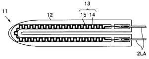
処置具2は、グリップ2A1と、シャフト2A2と、被処置体である生体組織LTを把持して処置を行う開閉可能な一対の挟持部11(第1挟持部11A、第2挟持部11B)からなる処置部10を有する。
The
なお、以下、符号の末尾にA、Bが付与された同じ機能の構成要素のそれぞれをいうときは符号A、Bを省略することがある。例えば、第1挟持部11Aおよび、第2挟持部11Bのそれぞれを挟持部11という。
In the following description, the symbols A and B may be omitted when referring to the components having the same function with A and B added to the end of the symbol. For example, each of the
グリップ2A1は、ケーブル2Lを介して本体部3に接続されている。術者が処置部10の開閉を操作する開閉ノブ2A3のあるグリップ2A1は、術者が握り易い形状、例えば略L字状である。グリップ2A1の一端には、処置部10と一体化し、開閉ノブ2A3の動作を処置部10に伝達するシャフト2A2が配設されている。一方、グリップ2A1の他端側は、術者に把持される把持部2A4である。
The grip 2A1 is connected to the
本体部3は、処置条件等を表示する表示部36と、術者が処置条件等を設定する設定操作部35とを前面パネルに有し、ケーブル4Lを介してフットスイッチ4が接続されている。フットスイッチ4のペダルを術者が足で押圧操作することにより、本体部3から処置具2への電力出力がON/OFF制御される。フットスイッチ4は必須の構成要素ではなく、術者が手元で操作するスイッチ等であってもよい。
The
図2Aおよび、図2Bに示すように、処置具2は、生体組織LTとの接触面である処置面11S(11SA、11SB)を介して熱エネルギ(THエネルギ)を生体組織LTに印加する。
As shown in FIGS. 2A and 2B, the
処置部10は、例えば、第2挟持部11Bが第1挟持部11Aに対して相対的に移動することにより開閉自在である。図2Aに示すように、開閉ノブ2A3が術者により押圧操作されていないときには、図示しない弾性部材の付勢力により第2挟持部11Bは第1挟持部11Aと近接状態または接触状態にある。これに対して、図2Bに示すように、弾性部材の付勢力よりも強い力で開閉ノブ2A3が術者により押圧操作されると、第2挟持部11Bは第1挟持部11Aから離れ、処置部10は開状態となる。処置部10が開状態のときに、第1挟持部11Aと第2挟持部11Bとの間に挿入された生体組織LTは、術者が開閉ノブ2A3の押圧操作をやめると、弾性部材の付勢力により第1挟持部11Aの処置面11SAと第2挟持部11Bの処置面11SBと間に挟まれ押圧された状態で保持される。
For example, the
図3A〜図4に示すように、挟持部11の処置面11Sはステンレスまたは銅等の金属からなる伝熱体12のおもて面(外面)である。そして、伝熱体12の裏面(内面)には発熱素子13が接合されている。発熱素子13の上面は、ポリイミド等の絶縁体16により覆われ、絶縁されている。
As shown in FIGS. 3A to 4, the
発熱素子13は、アルミナまたは窒化アルミニウム等の基板14の表面に発熱抵抗体15が形成されている。発熱抵抗体15は温度が上がると電気抵抗Rが高くなる正の抵抗温度係数の白金からなる。このため、後述するように、素子温度測定部39は、発熱抵抗体15の電気抵抗Rから発熱素子13(発熱抵抗体15)の温度T1を算出できる。発熱抵抗体15の材料には、NiCr合金、Ta、またはW等の各種の正の抵抗温度係数の高融点金属材料を用いてもよい。
The
発熱素子13は、本体部3から出力される発熱用電力(TH)を、熱エネルギとして生体組織LTに印加する出力部である。
The
発熱素子13はそれぞれの挟持部11A、11Bに配設されているが、発熱素子13は、少なくとも一方の挟持部11に配設されていればよい。
Although the
次に、図5を用いて生体組織接合システム1の構成について説明する。すでに説明したように、生体組織接合システム1は、処置具2と本体部3とフットスイッチ4とを有する。
Next, the configuration of the biological
本体部3は、発熱用電力(TH)電源30と、発熱用電力センサ(THセンサ)31と、設定部32と、算出部33と、制御部34と、記憶部38と、素子温度測定部39と、を具備する。
The
電源30は、熱エネルギのための発熱用電力(TH)を出力する。検出部であるTHセンサ31は、THの出力値(電圧および電流)を検出する。電圧と電流の積が電力Pである。
The
制御部34は、生体組織接合システム1の全体の制御を行う。
The
出力部の温度を測定する温度測定部である素子温度測定部39は、THの電圧および電流から発熱素子13の電気抵抗Rを算出し、算出した電気抵抗Rから出力部である発熱素子13の温度(素子温度)T1を算出することで、間接的に素子温度T1を測定する。すなわち、素子温度測定部39は、発熱素子13の抵抗温度係数にもとづく算出式、または、電気抵抗Rと素子温度T1との対応表等が記憶されている記憶部(不図示)を有する。なお、素子温度測定部39が、THの電圧および電流から、電気抵抗Rを算出しないで、直接、素子温度T1を算出してもよい。また、素子温度測定部39は発熱素子13の近傍に配設された熱電対等の温度センサにより素子温度T1を直接、測定してもよい。
The element
図6に示すように、素子温度T1と生体組織の温度(組織温度)T2とには温度差ΔTがある。そして、温度差ΔTは処置時間の経過につれて変化している。このため、素子温度T1にもとづいた制御では適切な処置を行うことが容易ではない場合がある。 As shown in FIG. 6, there is a temperature difference ΔT between the element temperature T1 and the temperature of the living tissue (tissue temperature) T2. The temperature difference ΔT changes as the treatment time elapses. For this reason, it may not be easy to perform an appropriate measure in the control based on the element temperature T1.
発明者は鋭意研究の結果、図7に示すように、温度差ΔTは、発熱用電力(TH)の出力値Pと強い相関があることを見出した。これは、出力値Pは素子温度T1が所定の素子温度設定値Tsetになるように定温制御されているため、温度差ΔTが大きいと、より大きな出力値PのTHが必要となるからである。 As a result of earnest research, the inventor found that the temperature difference ΔT has a strong correlation with the output value P of the heat generation power (TH) as shown in FIG. This is because the output value P is controlled at a constant temperature so that the element temperature T1 becomes the predetermined element temperature set value Tset, and therefore, if the temperature difference ΔT is large, a larger TH of the output value P is required. .
そして、生体組織接合システム1では、記憶部38には、素子温度T1と生体組織の温度T2との温度差ΔTを、電源30の出力値をもとに推定するための、表(テーブルデータ)または式が記憶されている。
In the biological
このため、T2は以下の(式1)から算出できる。 For this reason, T2 is computable from the following (Formula 1).
T2=T1−ΔT=T1−f(P) ・・・(式1) T2 = T1-ΔT = T1-f (P) (Formula 1)
なお、図7には、温度センサを用いて生体組織の温度を実測して得られたΔTに基づく、複数の実験データ(プロット)を最小二乗法にて1次式近似した直線を示している。 FIG. 7 shows a straight line obtained by approximating a plurality of experimental data (plots) by a least square method based on ΔT obtained by actually measuring the temperature of a living tissue using a temperature sensor. .
すなわち、図6に示した直線の式f(P)は、ΔT=αP+β (α:傾き、β:Y切片)である。式f(P)は2次式等でもよいし、電力Pを複数の範囲に区分し、区分毎に異なる複数の式から構成されていてもよい。また、表で記憶する場合には、表には例えば電力Pの5W毎に対応したΔTが記憶されている。 That is, the straight line expression f (P) shown in FIG. 6 is ΔT = αP + β (α: inclination, β: Y intercept). The expression f (P) may be a quadratic expression or the like, or the electric power P may be divided into a plurality of ranges and may be composed of a plurality of different expressions for each section. In the case of storing in a table, for example, ΔT corresponding to every 5 W of power P is stored in the table.
生体組織の種類等により、異なる式f(P)が記憶されていても良い。なお組織温度T2は生体組織の内部温度に限られるものではなく、処置面11Sと接している表面温度でもよい。
Different formulas f (P) may be stored depending on the type of living tissue. The tissue temperature T2 is not limited to the internal temperature of the living tissue, and may be a surface temperature in contact with the
算出部33は、処置している生体組織の温度T2を算出する。以下、説明の都合上、算出部33を、その機能から第1算出部33Aと第2算出部33Bとに分けて説明する。
The
第1算出部33Aは、電源30の出力値Pをもとに、予め記憶されている記憶された表または式を用いて、温度差ΔTを推定する。
The
第2算出部33Bは、素子温度測定部39が測定した素子温度T1と、第1算出部33Aが推定した温度差ΔTとから、(式1)を用いて組織温度T2を推定する。
The
設定部32は設定操作部35の操作等にもとづき、処置条件を設定する。生体組織接合システム1では設定部32は記憶部32Mを有する。半導体メモリ等からなる記憶部32Mは、例えば、生体組織の種類に応じた複数の処置条件を記憶してもよい。なお、設定操作部35は広義の設定部32Sの一部とみなすことができる。
The setting
制御部34を構成するCPU等が、素子温度測定部39、算出部33および設定部32の機能の少なくとも一部を有していてもよい。また、それぞれが独立したCPUであってもよい。また、半導体メモリ等からなる記憶部38が、設定部の記憶部32Mおよび算出部33の記憶部の機能を有していてもよい。逆に、算出部33が記憶部38の機能を有する半導体メモリ等を有していてもよい。
The CPU or the like constituting the
表示部36は、設定された処置条件、処置中の電力の出力値、および、組織温度T2等の情報等を術者に告知する告知部である。
The
生体組織接合システム1では、第2算出部33Bが推定した組織温度T2にもとづいて、制御部34が電源30を制御する。
In the biological
<生体組織接合システムの作動方法>
次に、図8のフローチャートに沿って、生体組織接合システム1の作動方法について説明する。
<Operation method of biological tissue bonding system>
Next, the operation method of the biological
<ステップS11>
例えば、以下のような処置条件が、設定操作部35を含む設定部32を介して設定される。
<Step S11>
For example, the following treatment conditions are set via the
組織温度設定値Tset:190℃
上限温度Tmax:200℃
処置時間t:10秒
Tissue temperature set value Tset: 190 ° C
Maximum temperature Tmax: 200 ° C
Treatment time t: 10 seconds
ここで、組織温度設定値Tsetは、制御部34が定温制御する目標温度である。上限温度Tmaxは、処置している生体組織が想定外の損傷を受け周辺部位にまで悪影響を及ぼすおそれが生じはじめる温度である。
Here, the tissue temperature set value Tset is a target temperature that the
すでに説明したように、従来の生体組織接合システムでは定温制御する目標温度として、素子温度T1が設定されていたのに対して、生体組織接合システム1では、組織温度T2が設定される。
As already described, the element temperature T1 is set as the target temperature for constant temperature control in the conventional biological tissue bonding system, whereas in the biological
<ステップS12>
図2Aに示したように、閉状態の処置部10が、例えば、腹壁を通して腹腔内に挿入される。術者がグリップ2A1の開閉ノブ2A3を握りしめる押圧操作をすると、第1挟持部11Aに対して第2挟持部11Bが開く。そして、処置対象の生体組織LTが、第1挟持部11Aの処置面11SAと第2挟持部11Bの処置面11SBとの間に配置される。この状態で、開閉ノブ2A3が開放されると、弾性部材の付勢力により、第1挟持部11Aに対して第2挟持部11Bが閉じ、図2Bに示すように、処置対象の生体組織LTは、第1挟持部11Aの処置面11SAと第2挟持部11Bの処置面11SBとの間に押圧状態で挟持される。
<Step S12>
As shown in FIG. 2A, the
<ステップS13>
術者がフットスイッチ4を足で押圧操作する。すると、制御部34は、TH電源30が発熱用電力(TH)を出力するように制御する。
<Step S13>
The surgeon presses the foot switch 4 with his / her foot. Then, the
<ステップS14>
素子温度測定部39が、発熱用電力の出力値P(電圧および電流)から発熱素子13の電気抵抗Rを算出し、算出した電気抵抗Rから発熱素子の温度(素子温度)T1を算出する。
<Step S14>
The element
生体組織接合システム1では、発熱素子13A、13Bの平均温度、または、発熱素子13A、13Bの一方の温度を素子温度T1とみなして、素子温度T1を算出する。
In the biological
<ステップS15>
第1算出部33Aが、出力値Pをもとに、予め記憶されている表または式を用いて、温度差ΔTを推定する。
<Step S15>
Based on the output value P, the
<ステップS16>
第2算出部33Bが、素子温度測定部39が測定した素子温度T1と、第1算出部33Aが推定した温度差ΔTとから、(式1)を用いて組織温度T2を推定する。
<Step S16>
The
<ステップS17>
制御部34は、組織温度T2が、上限温度Tmax超になった場合には、処置を中止する。このとき、制御部34が、表示部36に警告を表示することが好ましい。
<Step S17>
The
<ステップS18>
制御部34は、フットスイッチ4の押圧が無くなる(SW OFF:Yes)と処置を中止する。それまでは、ステップS13からの処置を繰り返し行う。
<Step S18>
The
生体組織接合システム1、本体部3(処置具制御装置)および生体組織接合システムの作動方法1では、実際に処置されている生体組織の温度T2に基づき制御が行われる。このため、組織温度T2が上限温度Tmax超になることがない。また、素子温度等により制御される従来の処置システム等よりも、より、適切な処置を行うことができる。
In the
<第1実施形態の変形例>
次に、第1実施形態の変形例1〜3の生体組織接合システム1A〜1C、処置具制御装置、および、生体組織接合システムの作動方法について説明する。なお、以下、(生体組織接合システム、処置具制御装置、および、生体組織接合システム1の作動方法)を、生体組織接合システム等という。生体組織接合システム1A〜1C等は、生体組織接合システム1等と類似しているので、同じ機能の構成要素には同じ符号を付し説明は省略する。
<Modification of First Embodiment>
Next, the biological
生体組織接合システム1では、印加される処置エネルギが熱エネルギであった。しかし、処置エネルギは、熱エネルギ、超音波エネルギ、光エネルギ、および、高周波電力エネルギのいずれかのエネルギであれば、同様の効果を得られる。
In the biological
<変形例1>
変形例1の生体組織接合システム1A等では、生体組織に処置エネルギとして光エネルギであるレーザ光が印加される。すなわち、電源はレーザ光を発生する光源に電力を出力する。
<
In the biological
レーザ光が印加された生体組織は発熱する。レーザ光の波長を選択することで、特定の処置部位を選択的に加熱することもできる。 The living tissue to which the laser light is applied generates heat. A specific treatment site can be selectively heated by selecting the wavelength of the laser beam.
<変形例2>
変形例2の生体組織接合システム1B等では、生体組織に処置エネルギとして超音波エネルギが印加される。すなわち、電源は超音波振動子に電力を出力する。
<
In the biological tissue joining system 1B and the like according to
生体組織接合システム1Bの処置具は、グリップ2A1の内部に超音波振動子を有し、挟持部11Aが超音波振動する。固定されている挟持部11Bとの間に挟持された生体組織は、摩擦熱により発熱する。
The treatment tool of the biological tissue joining system 1B has an ultrasonic vibrator inside the grip 2A1, and the sandwiching
<変形例3>
変形例3の生体組織接合システム1C等では、生体組織に処置エネルギとして高周波電力エネルギが印加される。すなわち、電源は高周波電力を出力する。
<
In the biological tissue bonding system 1C and the like according to
生体組織接合システム1Cの処置具の金属からなる伝熱体は高周波電力(HF)を生体組織に印加する電極としての機能を有する。電極12A、12Bに挟持されている生体組織LTに高周波電力が印加されると、生体組織LTはジュール熱により加熱される。
The heat transfer body made of metal of the treatment tool of the living tissue bonding system 1C has a function as an electrode for applying high frequency power (HF) to the living tissue. When high frequency power is applied to the living tissue LT sandwiched between the
第1実施形態の変形例の生体組織接合システム1A〜1C、処置具制御装置、および、生体組織接合システムの作動方法は、いずれも生体組織接合システム1等と同じように、出力部の温度T1と電源の出力値Pを測定し、温度T1と出力値Pとから温度差ΔTを推定し、温度差ΔTから組織温度T2を推定する。
As for the operation methods of the biological
そして、組織温度T2が、上限温度Tmax超になった場合には、処置を中止する。
すなわち、制御部34が、第2算出部33Bが推定した組織温度T2が上限温度Tmax超にならないように電源30を制御する。このため、変形例の生体組織接合システム1A〜1C等は、いずれも適切な処置を行うことが容易である。
When the tissue temperature T2 exceeds the upper limit temperature Tmax, the treatment is stopped.
That is, the
<第2実施形態>
次に、第2実施形態の生体組織接合システム1D等について説明する。生体組織接合システム1D等は、生体組織接合システム1等と類似しているので、同じ機能の構成要素には同じ符号を付し説明は省略する。
Second Embodiment
Next, a biological tissue bonding system 1D and the like according to the second embodiment will be described. Since the biological tissue bonding system 1D and the like are similar to the biological
生体組織接合システム1Dでは、例えば、処置具制御装置3Dの記憶部38が電源30の出力値Pだけでなく出力値Pおよび出力部(発熱素子13)の温度T1をもとに温度差ΔTを推定するための表または式を記憶しており、第1算出部33Aが電力の出力値Pおよび出力部の温度T1をもとに温度差ΔTを推定する。
In the biological tissue bonding system 1D, for example, the
すなわち、生体組織接合システム1Dでは、第1算出部33Aは、図8に示したステップS15において、温度差ΔTを、発熱素子13の素子温度T1と、発熱用電力(TH)の出力値Pと、から算出する。
That is, in the biological tissue bonding system 1D, the
すでに説明したように、組織温度T2と素子温度T1の温度差ΔTは、発熱用電力(TH)の出力値Pと強い相関がある。そして、出力値Pだけでなく、素子温度T1も考慮することで、より正確に温度差ΔTを推定できる。 As already described, the temperature difference ΔT between the tissue temperature T2 and the element temperature T1 has a strong correlation with the output value P of the heat generation power (TH). Then, by considering not only the output value P but also the element temperature T1, the temperature difference ΔT can be estimated more accurately.
ΔT=f(P、T1) ・・・(式2) ΔT = f (P, T1) (Formula 2)
図9に示すように、加熱処理の開始直後(初期期間L1)では、発熱素子13自体の熱容量等のため、素子温度T1は、ほぼ一定と見なすことができる程度に、非常にゆっくり上昇する。これに対して、発熱素子13が昇温中(昇温期間L2)は、素子温度T1は温度設定値Tsetよりも大幅に低い状態である。このため出力値Pは急激に増加する。そして、素子温度T1が温度設定値Tsetに近接してくると(昇温完了期間L3)、オーバーシュートを防止するために、出力値Pは減少に転ずるそして、安定状態になったら、出力値Pは更に減少しほぼ一定の値となる(安定期間L4)。
As shown in FIG. 9, immediately after the start of the heat treatment (initial period L1), the element temperature T1 rises very slowly to such an extent that it can be regarded as substantially constant due to the heat capacity of the
図10は、出力値Pと温度差ΔTとの関係を、上記4つの期間に区別してプロットしている。すなわち、期間L1のデータを黒三角マークで、期間L2のデータを黒丸マークで、期間L3のデータを白丸マークで、期間L4のデータを白三角マークで、それぞれプロットしている。 FIG. 10 plots the relationship between the output value P and the temperature difference ΔT by distinguishing the above four periods. That is, data for the period L1 is plotted with black triangle marks, data for the period L2 with black circle marks, data for the period L3 with white circle marks, and data for the period L4 with white triangle marks.
図10から明らかなように、出力値Pから温度差ΔTを算出する場合に、4つの期間に応じて算出式を変えることで、より高い精度での算出が可能である。ここで、第1算出部33Aは、4つの期間L1〜L4を、素子温度T1または出力値Pから判断する。
As is clear from FIG. 10, when calculating the temperature difference ΔT from the output value P, it is possible to calculate with higher accuracy by changing the calculation formula according to the four periods. Here, the
すなわち、素子温度T1の上昇開始直後が期間L1であり、上昇中が期間L2であり、素子温度T1が素子温度設定値Tsetに近接して出力値Pが減少し、減少速度が所定値以下になるまでが期間L3であり、それ以降が期間L4である。 That is, the period L1 is immediately after the start of the rise of the element temperature T1, the period L2 is during the rise, the element temperature T1 is close to the element temperature set value Tset, the output value P is decreased, and the decrease rate is the predetermined value or less. Until this is the period L3, the period thereafter is the period L4.
それぞれの期間における算出式は、適宜、設定できる。例えば、期間L1ではΔTを一定とみなし、期間L2〜L4では、1次式近似してもよい。また、5つ以上の期間に区別してもよいし、3つ以下の期間に区別してもよい。 The calculation formula for each period can be set as appropriate. For example, ΔT may be regarded as constant in the period L1, and linear approximation may be performed in the periods L2 to L4. Moreover, you may distinguish in five or more periods, and you may distinguish in three or less periods.
生体組織接合システム1D等は、処置システム1等よりも精度の高い温度差ΔTが推定できるため、より適切な処置ができる。
Since the biological tissue bonding system 1D and the like can estimate the temperature difference ΔT with higher accuracy than the
なお、温度差ΔTが、第1挟持部11Aの処置面11SAと第2挟持部11Bの処置面11SBとの間の押圧力PPの影響を受けることがある。このため、処置面11Sに圧力センサを配設し、押圧力PPも温度差ΔTの推定に用いることで、より精度の高い温度差ΔTが推定できる。なお、所定圧力以上の押圧力PPでは温度差ΔTは一定になる。このため、押圧力PPが所定圧力未満の場合には処置が開始されないように制御部34が電源30を制御してもよい。
Note that the temperature difference ΔT may be affected by the pressing force PP between the treatment surface 11SA of the
<第3実施形態>
次に、第3実施形態の生体組織接合システム1E等について説明する。生体組織接合システム1E等は、生体組織接合システム1等と類似しているので、同じ機能の構成要素には同じ符号を付し説明は省略する。
<Third Embodiment>
Next, the biological
生体組織接合システムEでは、処置具制御装置3Eの算出部33が、組織温度T2の時間積分値である加熱量(heating amount)Qを算出し、制御部34は加熱量Qが所定の加熱量設定値Qset以上になったら、電力の出力を減少または終了するように電源30を制御する。すなわち、生体組織接合システム1等では処置完了は、例えば予め設定された処置時間にもとづき制御されていたが、生体組織接合システム1Eでは加熱量Qにもとづき制御される。
In the biological tissue joining system E, the
良い処置結果を得るためには、処置エネルギの印加時間を適切に行う必要がある。印加時間が短いと接合強度が不十分であり、印加時間が長いと周囲の組織に悪影響を及ぼしたり、接合強度が不十分になったりする。 In order to obtain a good treatment result, it is necessary to appropriately apply the treatment energy application time. When the application time is short, the bonding strength is insufficient, and when the application time is long, the surrounding tissue is adversely affected, or the bonding strength is insufficient.
加熱量Qは、温度の時間積分値、すなわち、温度と印加時間の積であり、例えば「℃秒」の単位で示される。例えば、以下の(式3)により、処置開始(時間0)から時間t1までの加熱量Qが算出される(図11参照)。なお、図11における下限温度Tminについては後述する。 The heating amount Q is a time integral value of the temperature, that is, the product of the temperature and the application time, and is expressed in units of “° C. seconds”, for example. For example, the heating amount Q from the start of treatment (time 0) to time t1 is calculated by the following (formula 3) (see FIG. 11). Note that the lower limit temperature Tmin in FIG. 11 will be described later.
(式3)

加熱量Qは、所定時間毎、例えば、1秒毎の生体組織温度T2を加算した、単位が「℃」の積算値(積算温度)として表現することもできる。すなわち、温度の時間積分値と積算温度とは単位は異なるが同じ状態を示す物理量である。なお、加熱量Qは、ジュールを単位とする熱量(calorie)とは全く異なる物理量である。 The heating amount Q can also be expressed as an integrated value (integrated temperature) with a unit of “° C.” obtained by adding the biological tissue temperature T2 every predetermined time, for example, every second. That is, the time integral value of temperature and the integrated temperature are physical quantities indicating the same state, although the units are different. The heating amount Q is a physical quantity that is completely different from the calorie in units of joules.
図12は、加熱量Qと処置された生体組織LTの接合強度との関係を示している。図12から、加熱量Qを基準とすることにより、良い処置結果が得られることは明らかである。すなわち、加熱量Qが、所定の加熱量QA以上であれば、実用上、十分な接合強度SAを得ることができる。加熱量QAは予め実験が行われ、得られた実験値が記憶部32Mに記憶されている。
FIG. 12 shows the relationship between the heating amount Q and the bonding strength of the treated living tissue LT. From FIG. 12, it is clear that a good treatment result can be obtained by using the heating amount Q as a reference. That is, if the heating amount Q is equal to or greater than the predetermined heating amount QA, a practically sufficient bonding strength SA can be obtained. The heating amount QA is previously tested, and the obtained experimental value is stored in the
<生体組織接合システムの作動方法>
次に、図13のフローチャートに沿って、生体組織接合システム1Eの作動方法について説明する。
<Operation method of biological tissue bonding system>
Next, an operation method of the biological
<ステップS21>
例えば、以下のような処置条件が、設定操作部35を含む設定部32を介して設定される。
<Step S21>
For example, the following treatment conditions are set via the
組織温度設定値Tset:220℃
加熱量設定値Qset:800℃秒
下限温度Tmin:50℃
上限温度Tmax:230℃
Tissue temperature set value Tset: 220 ° C
Heating amount set value Qset: 800 ° C. Lower limit temperature Tmin: 50 ° C.
Maximum temperature Tmax: 230 ° C
ここで、下限温度Tminは、生体組織に変化が生じはじめる温度である。言い替えれば下限温度Tminになるまでは、生体組織は実質的には処置されない。 Here, the lower limit temperature Tmin is a temperature at which the biological tissue starts to change. In other words, the living tissue is not substantially treated until the lower limit temperature Tmin is reached.
すでに説明したように、従来の生体組織接合システムでは、処置条件として、処置時間(処置エネルギの印加印加時間)が設定されていたのに対して、生体組織接合システム1では、組織温度T2の熱エネルギの印加終了までの時間積分値である加熱量設定値Qsetが設定される。
As described above, in the conventional tissue joining system, the treatment time (application time of application of treatment energy) is set as the treatment condition, whereas in the living
なお、処置条件は、例えば、記憶部32Mに記憶されている複数の処置条件の中から処置に応じて術者が設定できるが、後述するように、生体組織LTの種類に応じて設定部32が自動的に設定してもよい。
The treatment condition can be set by the operator according to the treatment from among a plurality of treatment conditions stored in the
すなわち、それぞれの条件は個別に設定されてもよいし、複数の条件が予め設定されている処置条件セットとして選択されてもよい。例えば、以下のように、処置する生体組織LTの種類に応じて予め複数の処置条件セットLV1〜LV3が記憶部32Mに記憶されていてもよい。
That is, each condition may be set individually, or may be selected as a treatment condition set in which a plurality of conditions are set in advance. For example, as described below, a plurality of treatment condition sets LV1 to LV3 may be stored in the
(LV1)
組織温度設定値Tset:180℃
加熱量設定値Qset:1000℃秒
下限温度Tmin:50℃
上限温度Tmax:190℃
(LV1)
Tissue temperature set value Tset: 180 ° C
Heating amount set value Qset: 1000 ° C. Lower limit temperature Tmin: 50 ° C.
Maximum temperature Tmax: 190 ° C
(LV2)
組織温度設定値Tset:190℃
加熱量設定値Qset:2500℃秒
下限温度Tmin:50℃
上限温度Tmax:200℃
(LV2)
Tissue temperature set value Tset: 190 ° C
Heating amount set value Qset: 2500 ° C. Second lower limit temperature Tmin: 50 ° C.
Maximum temperature Tmax: 200 ° C
(LV3)
組織温度設定値Tset:200℃
加熱量設定値Qset:3500℃秒
下限温度Tmin:50℃
上限温度Tmax:210℃
(LV3)
Tissue temperature set value Tset: 200 ° C
Heating amount set value Qset: 3500 ° C. Lower limit temperature Tmin: 50 ° C.
Maximum temperature Tmax: 210 ° C
<ステップS22〜ステップS27>
図8に示したステップS12〜ステップS17と略同じであるので説明は省略する。
<Step S22 to Step S27>
Since it is substantially the same as step S12 to step S17 shown in FIG.
<ステップS28>
制御部34は、組織温度T2が下限温度Tmin以上まで上昇したか判断する。下限温度Tmin以上になったら(YES)、ステップS16に移行する。すなわち、下限温度Tmin未満の間(時間0からt0までの間)は、加熱量Qは算出されない。
<Step S28>
The
<ステップS29>
算出部33は、組織温度T2の時間積分値である加熱量Qを算出する。
<Step S29>
The
(式3)で示される加熱量Qは、所定時間毎、例えば1秒毎に、ΔQ(組織温度T2×1秒)が、それまでの加熱量Qに加算される。 As for the heating amount Q shown in (Equation 3), ΔQ (tissue temperature T2 × 1 second) is added to the heating amount Q so far every predetermined time, for example, every second.
なお、発熱素子13の素子温度T1の時間積分値である加熱量にもとづいて同様の制御を行っても、時間にもとづく従来の制御と比べると、良い処置結果を得られる。しかし、より的確な処置を行うためには、組織温度T2を用いて制御することが好ましい。
Even if the same control is performed based on the heating amount that is the time integral value of the element temperature T1 of the
<ステップS30>
制御部34は、加熱量Qが、加熱量設定値Qset以上になる(YES)と、TH電源30を制御し、THの出力を終了する。すなわち、加熱量設定値Qsetと加熱量Qとにもとづき、THの出力が終了する。なお、制御部34は、TH電源30を制御しTHの出力が生体組織に実質的に影響の無いレベルまで減少してもよい。
<Step S30>
When the heating amount Q becomes equal to or higher than the heating amount set value Qset (YES), the
生体組織接合システム1Eは、熱エネルギの印加時間が、加熱量Qを基準に制御されるため、良い処置結果を容易に得られる。すなわち、生体組織接合システム1E等の作動方法は操作性がよい。
Since the application time of heat energy is controlled based on the heating amount Q, the biological
また、算出部33が算出する加熱量Qの加熱量設定値Qsetに対する比率Q/Qsetが表示部36の告知部36Bに表示されることが好ましい。例えば、告知部36Bにバーグラフにより処置進行の状態が表示される。術者は、告知部36Bの表示により処置進行の様子を確認できる。
Further, the ratio Q / Qset of the heating amount Q calculated by the calculating
なお、上記比率Q/Qsetの術者への告知は、術者が認識可能であれば、表示部36の告知部36Bに限られるものではなく、音(音声情報、メロディの種類、周波数の変化)、または、振動強度等により告知する告知部であってもよい。
Note that the notification of the ratio Q / Qset to the surgeon is not limited to the notification unit 36B of the
<第4実施形態>
次に、第4実施形態の生体組織接合システム1F等について説明する。生体組織接合システム1F等は、生体組織接合システム1、1D等と類似しているので、同じ機能の構成要素には同じ符号を付し説明は省略する。
<Fourth embodiment>
Next, a biological
生体組織接合システム1Fの処置具2Fは、処置面11SA、11SBを介して高周波電力エネルギ(HFエネルギ)と熱エネルギ(THエネルギ)とを順に生体組織LTに印加する。
The
HFエネルギは、生体組織の細胞膜を破壊することによってタンパク質をはじめとする高分子化合物を含んだ細胞内成分を放出し、コラーゲンをはじめとする細胞外成分と均一化させる作用を有する。また、HFエネルギは、生体組織の温度を上昇させる作用も有する。そして、生体組織の均一化および温度上昇により、その後に行われる熱エネルギの印加による、脱水処置および生体組織の接合が促進されている。 The HF energy has an action of releasing intracellular components including a high molecular compound such as a protein by homogenizing a cell membrane of a living tissue and making it uniform with extracellular components such as collagen. Moreover, HF energy also has the effect | action which raises the temperature of a biological tissue. Then, the homogenization of the living tissue and the temperature rise promote the dehydration treatment and the joining of the living tissue by the application of the thermal energy performed thereafter.
図14に示すように、生体組織接合システム1Fの処置具2Fの金属からなる伝熱体は電極12としての機能も有する。そして、処置具制御装置である本体部3Fは、第1電源である高周波電力(HF)電源30Aと、第2電源である発熱用電力(TH)電源30Bと、HFセンサ31Aと、THセンサ31Bと、設定部32と、算出部33と、制御部34と、を具備する。
As shown in FIG. 14, the heat transfer body made of metal of the
HF電源30Aは、第1電力である高周波電力(HF)を出力する。TH電源30Bは、第2電力である発熱用電力(TH)を出力する。なお、HF電源30AとTH電源30Bとは同時に電力を出力することはないため、一つの共用電源であってもよい。この場合には、HFセンサ31AとTHセンサ31Bも共用でよい。
The
第1検出部であるHFセンサ31Aは、HFの出力値(電圧および電流)を検出する。第2検出部であるTHセンサ31Bは、THの出力値(電圧および電流)を検出する。
The HF sensor 31A as the first detection unit detects the output value (voltage and current) of HF. The
<生体組織接合システムの作動方法>
図15に示すように、生体組織接合システム1Fでは、HFエネルギの印加終了後に、THエネルギの印加が開始される(時間t=t1)。そして、制御部34は、加熱量Qで定義される組織温度T2の時間積分値にもとづき、処置終了(時間t=t2)を制御する。
<Operation method of biological tissue bonding system>
As shown in FIG. 15, in the biological
すなわち、HFエネルギ印加による高周波電力エネルギ加熱量(第1加熱量)Q1と、THエネルギ印加による熱エネルギ加熱量(第2加熱量)Q2との加算値である合計加熱量QTが、予め設定された加熱量設定値Qset以上になる(時間t=t2)と、制御部34はTH電源30BがTHエネルギ印加を終了するように制御する。すなわち、
That is, a total heating amount QT that is an addition value of the high-frequency power energy heating amount (first heating amount) Q1 by applying HF energy and the thermal energy heating amount (second heating amount) Q2 by applying TH energy is set in advance. When the heating amount becomes equal to or greater than the set value Qset (time t = t2), the
Qset≦Q1+Q2 ・・・(式4) Qset ≦ Q1 + Q2 (Formula 4)
次に図16のフローチャートに沿って、生体組織接合システム1Fの作動方法について詳細に説明する。
Next, the operation method of the biological
<ステップS31>
例えば、以下のような処置条件が、設定操作部35を含む設定部32により設定される。
<Step S31>
For example, the following treatment conditions are set by the setting
HF出力設定値Pset:60W
HF終了インピーダンスZset:120Ω
素子温度設定値Tset:180℃
加熱量設定値Qset:1000℃秒
HF output set value Pset: 60W
HF termination impedance Zset: 120Ω
Element temperature set value Tset: 180 ° C
Heating amount set value Qset: 1000 ° C second
なお、素子温度設定値Tsetは、HF印加終了時の組織温度(100℃±30℃)よりも高い70℃超、例えば100℃超に設定される。 The element temperature set value Tset is set to be higher than 70 ° C., for example, higher than 100 ° C., higher than the tissue temperature at the end of HF application (100 ° C. ± 30 ° C.).
また、生体組織接合システム1D等と同じように、下限温度Tminおよび上限温度Tmaxも設定され、制御部34は、下限温度Tminおよび上限温度Tmaxに基づいた制御を行う。しかし、その制御は生体組織接合システム1D等と同じであるので、説明は省略する。
Similarly to the living tissue bonding system 1D and the like, a lower limit temperature Tmin and an upper limit temperature Tmax are also set, and the
なお、設定部32が一対の挟持部11に挟持された生体組織LTの特性に応じて加熱量設定値Qsetを自動的に設定してもよい。
The setting
例えば、生体組織LTが挟持された一対の挟持部11A、11Bの間隔G、および、HFの初期インピーダンスの少なくともいずれかにもとづき加熱量設定値Qsetが自動的に設定される。
For example, the heating amount set value Qset is automatically set based on at least one of the gap G between the pair of holding
間隔Gは被処置体である生体組織LTの大きさの情報である。HFの初期インピーダンスは、生体組織LTの水分量を含む組織情報である。また、HFの初期インピーダンスとして、インピーダンス最小値、または、インピーダンスが所定値以下の時間、等を用いることができる。 The interval G is information on the size of the living tissue LT that is the object to be treated. The initial impedance of HF is tissue information including the moisture content of the living tissue LT. Further, as the initial impedance of HF, a minimum impedance value, a time when the impedance is equal to or less than a predetermined value, or the like can be used.
さらに、術者が設定操作部35により術式を選択すると、一連の処置の処置条件が設定部32により設定され、例えば処置Aが終わると設定部32は、自動的に処置Bの処置条件を設定してもよい。例えば、術式が、「肺葉切除術」の場合には、(処置A)肺葉動脈封止と、(処置B)肺葉静脈封止と、(処置C)肺葉気管支封止と、(処置D)肺葉間の実質臓器封止とが連続的に順に行われる場合に、術者が術式を選択するだけで一連の(処置A)〜(処置D)の処置条件が設定されるため、操作性がよい。
Further, when the surgeon selects a technique using the
<ステップS32>
処置対象の生体組織LTは、第1挟持部11Aの処置面11SAと第2挟持部11Bの処置面11SBとの間に押圧状態で挟持される。
<Step S32>
The living tissue LT to be treated is sandwiched in a pressed state between the treatment surface 11SA of the
<ステップS33>
処置部10に生体組織LTを挟持した状態で、術者がフットスイッチ4を足で押圧操作する。すると、制御部34は処置を開始する。すなわち、制御部34は、まず、HF電源30Aが高周波電力(HF)を出力するように制御する。HFは、ケーブル2Lを介して処置具2の電極12A、12Bに伝達される。すると、電極12A、12Bに挟持されている生体組織LTに高周波電力が印加され、生体組織LTはジュール熱により加熱される。
<Step S33>
The operator presses the foot switch 4 with his / her foot while the living tissue LT is held between the
すなわち、HFエネルギは、電極12Aと電極12Bと間のHFの通電経路にある生体組織自体を発熱させる。このため、HFエネルギ印加工程では、厚さの厚い生体組織LTであっても中心部まで温度ムラを生じることなく、組織温度T2が上昇する。なお、処置部10は発熱しないが、発熱した生体組織LTからの伝熱により素子温度T1も上昇する。
That is, the HF energy causes the living tissue itself in the HF energization path between the
制御部34は、HFセンサ31Aが検出したHFの電流および電圧にもとづいて、HFの出力値P1を、HF出力設定値Pset、例えば60Wで、定電力制御する。
Based on the HF current and voltage detected by the HF sensor 31A, the
<ステップS34>
算出部33は、組織温度T2を生体組織LTに挿入された温度センサ19、または赤外線センサ等によって測定し、組織温度T2の時間積分値(積算値)である高周波電力加熱量(第1加熱量)Q1を算出する。
<Step S34>
The
ここで、図15に示したように、HFエネルギ印加時の組織温度T2は、初期に急激に増加した後は、生体組織LTが水を含むため一定とみなすことができる。すなわち、エネルギが印加されても水を含む生体組織LTの温度は、例えば大気圧では一定温度である沸点(100℃)近傍の温度、例えば100℃±30℃に保持される。 Here, as shown in FIG. 15, the tissue temperature T2 at the time of HF energy application can be considered constant after the initial rapid increase because the living tissue LT contains water. That is, even when energy is applied, the temperature of the living tissue LT including water is maintained at a temperature near the boiling point (100 ° C.), which is a constant temperature at atmospheric pressure, for example, 100 ° C. ± 30 ° C.
このため、処置開始後、時間tまでの第1加熱量Q1は、センサ等を用いることなく、以下の(式5)により算出してもよい。 For this reason, the first heating amount Q1 up to the time t after the start of treatment may be calculated by the following (Formula 5) without using a sensor or the like.
Q1≒T2×t≒100℃×t ・・・(式5) Q1≈T2 × t≈100 ° C. × t (Formula 5)
さらに、算出部33による第1加熱量Q1の算出(ステップS34)は、後述するステップS36の後に、以下の(式6)を用いて行われてもよい。
Further, the calculation (step S34) of the first heating amount Q1 by the
Q1=100℃×t1・・・(式6)
ただし、t1;HFエネルギ印加時間
Q1 = 100 ° C. × t1 (Formula 6)
However, t1; HF energy application time
以上の説明のように、S34では、HFを定電力制御しHFエネルギを印加しながら、組織温度T2を所定の一定温度(100℃)とみなして時間積分値である第1加熱量Q1が算出されてもよい。 As described above, in S34, the first heating amount Q1, which is a time integral value, is calculated by considering the tissue temperature T2 as a predetermined constant temperature (100 ° C.) while applying constant power control to HF and applying HF energy. May be.
<ステップS35>
生体組織接合システム1Fでは、HFエネルギ印加を開始すると、HFセンサ31Aが検出するHFの電圧および電流からインピーダンスZが算出部33により算出される。
<Step S35>
In the
処置の進行にともなう生体組織LTの変性にともなう脱水等により、インピーダンスZは上昇する。制御部34は、インピーダンスZが設定された、HF終了インピーダンスZset以上になるまで(No)、S33からの処置を行う。
Impedance Z rises due to dehydration and the like accompanying the degeneration of the living tissue LT as the treatment progresses. The
<ステップS36>
制御部34は、インピーダンスZが設定された、HF終了インピーダンスZset以上になったら、(YES)、S26において、HF電源30Aを制御しHFの出力を終了する(t=t1)。
<Step S36>
When the impedance Z becomes equal to or higher than the set HF end impedance Zset (YES), the
すなわち、HFのインピーダンスZにもとづいて、HFの出力が終了する。 That is, based on the impedance Z of HF, the output of HF ends.
<ステップS37>
制御部34は、HFエネルギにかえてTHエネルギを生体組織LTに印加する制御を開始する。
<Step S37>
The
THエネルギ印加では、制御部34は、処置部10の素子温度T1にもとづき、TH電源30Bの出力値P2を定温制御する。言い換えれば、発熱素子13は、S31で設定された素子温度設定値Tsetとなるように制御される。THは直流でも高周波でもよく、高周波の場合の周波数はHFと同じでもよい。
In TH energy application, the
なお、制御部34は処置システム1等と同じように、組織温度T2にもとづき、TH電源30Bの出力値P2を定温制御してもよい。
Note that the
電極12から生体組織LTに印加される高周波電力(HF)は、ジュール熱として生体組織LTを加熱するのに対して、発熱用電力(TH)は、直接、熱エネルギを生体組織LTに伝熱する。処置面11Sを介して生体組織LTに伝熱される熱(TH)エネルギは、素子温度設定値Tsetに応じて、生体組織LTの変性状態、例えば水分量等によらず、組織温度T2を100℃超の温度まで加熱できる。
The high frequency power (HF) applied from the
<ステップS38>
算出部33は、組織温度T2の時間積分値である第2加熱量(熱エネルギ加熱量)Q2を算出する。すなわち、S38では、素子温度測定部39(不図示)がTHを電気抵抗Rから素子温度T1を算出し、素子温度T1にもとづき定温制御し生体組織LTに熱エネルギを印加する。そして、第1算出部33Aが電源30Bの出力値をもとに、記憶部38(不図示)に記憶された第2の表または第2の式を用いて、温度差ΔTを推定する。第2の表および第2の式は、TH電力が印加された発熱素子の温度T1BとTHエネルギが印加された生体組織の温度(組織温度)T2との温度差ΔT2を、TH電源の出力値P2をもとに推定するための、実験に基づき予め取得されている表または式である。
<Step S38>
The
<ステップS39>
制御部34は、組織温度T2が、上限温度Tmax超になった場合には、処置を中止する。
<Step S39>
The
<ステップS40>
算出部33は、組織温度T2の時間積分値である第2加熱量Q2が算出する。さらに、算出部33は、第1加熱量Q1と第2加熱量Q2とを加算した合計加熱量QTを算出する。
<Step S40>
The
<ステップS41>
制御部34は、合計加熱量QTが、加熱量設定値Qset以上になる(YES)と、TH電源30Bを制御し、THの出力を終了する(t=t2)。すなわち、加熱量設定値Qsetと合計加熱量QTとにもとづき、THの出力が終了する。
<Step S41>
When the total heating amount QT becomes equal to or greater than the heating amount set value Qset (YES), the
ここで、第1加熱量Q1は、S36以降の工程では、すでに算出されており増減しないため、制御部34は、以下の(式7)で示される加熱残量ΔQがゼロになったらTHの出力を終了してもよい。
加熱残量ΔQ=加熱量設定値Qset−第1加熱量Q1−第2加熱量Q2 ・・・(式7)
Here, since the first heating amount Q1 has already been calculated and does not increase or decrease in the steps after S36, the
Heating remaining amount ΔQ = heating amount set value Qset−first heating amount Q1−second heating amount Q2 (Expression 7)
なお、合計加熱量QTまたは加熱残量ΔQは、制御部34が算出してもよい。また、HF印加工程においては加熱量Qを算出しないで、TH印加工程においてのみ加熱量Qを算出してもよい。
Note that the
生体組織接合システム1F等は、エネルギの印加時間、すなわちエネルギ印加終了が、生体組織温度T2の加熱量Qを用いて制御されるため、良い処置結果を容易に得られる。このため、生体組織接合システム1F等は操作性がよい。
The biological
なお、上記説明では、最初に印加される第1エネルギが高周波電力エネルギで、次に印加される第2エネルギが熱エネルギの場合について説明した。しかし、第1エネルギが、高周波電力エネルギ、熱エネルギ、光エネルギ、および、超音波エネルギのいずれかのエネルギで、第2エネルギが、第1エネルギと異なるいずれかのエネルギであれば、同様の効果を得られる。 In the above description, the case where the first energy applied first is high-frequency power energy and the second energy applied next is thermal energy has been described. However, if the first energy is any one of high-frequency power energy, thermal energy, light energy, and ultrasonic energy, and the second energy is any energy different from the first energy, the same effect is obtained. Can be obtained.
すなわち、処置具が生体組織に、熱エネルギ、超音波エネルギ、光エネルギ、および、高周波電力エネルギから選択される2以上の前記処置エネルギを順に印加し、制御部が、少なくともいずれかの処置エネルギの出力の減少または終了を前記加熱量に基づいて行う生体組織接合システムは、生体組織接合システム1Eと同様の効果を有する。
That is, the treatment tool sequentially applies two or more treatment energy selected from thermal energy, ultrasonic energy, light energy, and high-frequency power energy to the living tissue, and the control unit applies at least one of the treatment energy. The biological tissue joining system that performs output reduction or termination based on the heating amount has the same effect as the biological
例えば、HFエネルギの印加により血管を止血した後に超音波エネルギの印加により血管を切離する生体組織接合システムでも、生体組織接合システム1Dと同様の制御を行うことで同様の効果を有する。 For example, a biological tissue joining system that stops a blood vessel by applying ultrasonic energy after the blood vessel is stopped by applying HF energy has the same effect by performing the same control as that of the biological tissue joining system 1D.
また、一対の挟持部11に生体組織LTが把持されるバイポーラ処置具について説明したが、モノポーラ処置具であっても、同様に合計加熱量QTを基準に制御される生体組織接合システムであれば良い処置結果を容易に得られる。
In addition, the bipolar treatment tool in which the living tissue LT is grasped by the pair of sandwiching
本発明は上述した実施形態等に限定されるものではなく、本発明の要旨を変えない範囲において、種々の変更、改変等ができる。 The present invention is not limited to the above-described embodiments and the like, and various changes and modifications can be made without departing from the scope of the present invention.
本出願は、2013年8月2日に米国に出願された出願番号61/861、683を優先権主張の基礎として出願するものであり、上記の開示内容は、本願明細書、請求の範囲、図面に引用されたものとする。 This application is filed on the basis of application claim No. 61 / 861,683, filed in the United States on August 2, 2013, and the above disclosure is disclosed in the present specification, claims, It shall be cited in the drawing.
1、1A〜1F ・・・ 生体組織接合システム
2 ・・・ 処置具
3 ・・・ 本体部(処置具制御装置)
13 ・・・ 発熱素子
19 ・・・ 温度センサ
30 ・・・ 電源
33 ・・・ 算出部
33A ・・・ 第1算出部
33B ・・・ 第2算出部
34 ・・・ 制御部
39 ・・・ 素子温度測定部
DESCRIPTION OF
DESCRIPTION OF
Claims (19)
前記挟持部に挟持された前記生体組織を接合するための処置エネルギを発生するための電源と、
前記挟持部に設けられて、前記処置エネルギを前記生体組織に出力するための出力部と、
前記出力部の温度を測定するための温度測定部と、
前記温度測定部で測定された前記出力部の温度と、前記挟持部で挟持された前記生体組織の温度との温度差と、前記電源から前記挟持部に出力する出力値との相関関係を示す予め記憶された表または式を用いて、前記処置エネルギ印加時間に応じて前記電源の前記出力値をもとに前記表または前記式から前記温度差を推定する第1算出部と、
前記温度測定部が測定した前記出力部の温度と、前記第1算出部が推定した前記温度差とから、前記生体組織の温度を推定する第2算出部と、
前記第2算出部が推定した生体組織の温度にもとづいて、前記電源を制御する制御部と、
を具備することを特徴とする生体組織接合システム。 A clamping part for clamping the biological tissue;
A power source for generating treatment energy for joining the living tissue sandwiched between the sandwiching portions;
An output unit provided in the sandwiching unit for outputting the treatment energy to the living tissue;
A temperature measuring unit for measuring the temperature of the output unit;
A correlation between a temperature difference between the temperature of the output unit measured by the temperature measuring unit and the temperature of the living tissue held by the holding unit and an output value output from the power source to the holding unit is shown. Using a prestored table or equation, a first calculator for estimating the temperature difference from the table or equation based on the output value of the power source according to the treatment energy application time;
A second calculation unit that estimates the temperature of the living tissue from the temperature of the output unit measured by the temperature measurement unit and the temperature difference estimated by the first calculation unit;
A control unit for controlling the power source based on the temperature of the living tissue estimated by the second calculation unit;
A biological tissue bonding system comprising:
前記出力部が前記電力を前記熱エネルギに変換する発熱素子であることを特徴とする請求項3に記載の生体組織接合システム。 The treatment energy is thermal energy;
The living tissue joining system according to claim 3, wherein the output unit is a heating element that converts the electric power into the thermal energy.
前記挟持部に挟持された前記生体組織を接合するための前記処置エネルギを発生するための電源と、 A power source for generating the treatment energy for joining the living tissue sandwiched between the sandwiching portions;
前記挟持部に設けられて、前記処置エネルギを前記生体組織に出力するための出力部と、 An output unit provided in the sandwiching unit for outputting the treatment energy to the living tissue;
前記出力部の温度を測定する温度測定部と、 A temperature measuring unit for measuring the temperature of the output unit;
前記温度測定部で測定された前記出力部の温度と、前記挟持部で挟持された前記生体組織の温度との温度差と、前記電源から前記挟持部に出力する出力値との相関関係を示す予め記憶された表または式を用いて、前記処置エネルギ印加時間に応じて前記電源からの前記出力値を前記表又は前記式から前記温度差を推定する第1算出部と、 A correlation between a temperature difference between the temperature of the output unit measured by the temperature measuring unit and the temperature of the living tissue held by the holding unit and an output value output from the power source to the holding unit is shown. Using a table or formula stored in advance, a first calculator that estimates the temperature difference from the table or formula based on the output value from the power source according to the treatment energy application time;
前記温度測定部が測定した前記出力部の温度と、前記第1算出部が推定した前記温度差とから、生体組織の温度を推定する第2算出部と、 A second calculation unit that estimates the temperature of the living tissue from the temperature of the output unit measured by the temperature measurement unit and the temperature difference estimated by the first calculation unit;
前記第2算出部が推定した前記生体組織の温度にもとづいて、前記処置エネルギのための電力を発生する電源を制御する制御部と、 A control unit that controls a power source that generates electric power for the treatment energy based on the temperature of the living tissue estimated by the second calculation unit;
を具備することを特徴とする処置具制御装置。 A treatment instrument control device comprising:
温度測定部が前記出力部の温度を測定するステップと、 A temperature measuring unit measuring the temperature of the output unit;
前記温度測定部で測定された前記出力部の温度と、前記挟持部で挟持された前記生体組織の温度との温度差と、前記電源から前記挟持部に出力する出力値との相関関係を示す予め記憶された表または式を用いて、第1算出部が前記処置エネルギ印加時間に応じて前記電源からの前記出力値を前記表又は前記式から得られる前記温度差を推定するステップと、 A correlation between a temperature difference between the temperature of the output unit measured by the temperature measuring unit and the temperature of the living tissue held by the holding unit and an output value output from the power source to the holding unit is shown. Using a table or formula stored in advance, a first calculating unit estimating the temperature difference obtained from the table or formula based on the output value from the power source according to the treatment energy application time; and
第2算出部が、前記温度測定部が測定した前記出力部の温度と、前記第1算出部が推定した前記温度差とから、前記生体組織の温度を推定するステップと、 A second calculating unit estimating the temperature of the living tissue from the temperature of the output unit measured by the temperature measuring unit and the temperature difference estimated by the first calculating unit;
制御部が、前記第2算出部が推定した生体組織温度にもとづいて前記電源を制御するステップと、 A control unit controlling the power supply based on the biological tissue temperature estimated by the second calculation unit;
を具備することを特徴とする生体組織接合システムの作動方法。 A method for operating a biological tissue bonding system, comprising:
前出力部が前記電力を前記熱エネルギに変換する発熱素子であることを特徴とする請求項10に記載の生体組織接合システムの作動方法。 The operating method of the biological tissue bonding system according to claim 10, wherein the front output unit is a heating element that converts the electric power into the thermal energy.
Applications Claiming Priority (3)
| Application Number | Priority Date | Filing Date | Title |
|---|---|---|---|
| US201361861683P | 2013-08-02 | 2013-08-02 | |
| US61/861,683 | 2013-08-02 | ||
| PCT/JP2014/070349 WO2015016347A1 (en) | 2013-08-02 | 2014-08-01 | Treatment system, instrument control device, and treatment system operation method |
Publications (2)
| Publication Number | Publication Date |
|---|---|
| JP5816774B2 true JP5816774B2 (en) | 2015-11-18 |
| JPWO2015016347A1 JPWO2015016347A1 (en) | 2017-03-02 |
Family
ID=52431870
Family Applications (1)
| Application Number | Title | Priority Date | Filing Date |
|---|---|---|---|
| JP2015516316A Active JP5816774B2 (en) | 2013-08-02 | 2014-08-01 | Biological tissue joining system, treatment instrument control device, and operating method of biological tissue joining system |
Country Status (5)
| Country | Link |
|---|---|
| US (1) | US10342596B2 (en) |
| EP (1) | EP3000425A4 (en) |
| JP (1) | JP5816774B2 (en) |
| CN (1) | CN105338917B (en) |
| WO (1) | WO2015016347A1 (en) |
Families Citing this family (8)
| Publication number | Priority date | Publication date | Assignee | Title |
|---|---|---|---|---|
| DE112015006004T5 (en) * | 2015-02-27 | 2017-10-26 | Olympus Corporation | Medical treatment device, method for operating a medical treatment device and treatment method |
| US10213253B2 (en) * | 2015-12-24 | 2019-02-26 | Biosense Webster (Israel) Ltd. | Estimating a temperature during ablation |
| WO2017122345A1 (en) | 2016-01-15 | 2017-07-20 | オリンパス株式会社 | Energy control device and treatment system |
| JPWO2017130384A1 (en) * | 2016-01-29 | 2018-12-13 | オリンパス株式会社 | Treatment tool and treatment system |
| JP6214833B1 (en) | 2016-04-26 | 2017-10-18 | オリンパス株式会社 | Treatment system and control device |
| CN109640853B (en) * | 2016-08-04 | 2021-10-22 | 奥林巴斯株式会社 | control device |
| WO2019142278A1 (en) * | 2018-01-17 | 2019-07-25 | オリンパス株式会社 | Heating device, treatment system, and heating control method |
| CN121714357A (en) * | 2026-02-24 | 2026-03-24 | 核工业四一六医院 | Anti-adhesion high-frequency electric wave cervical LEEP operation electric cutter |
Family Cites Families (18)
| Publication number | Priority date | Publication date | Assignee | Title |
|---|---|---|---|---|
| US5906614A (en) | 1991-11-08 | 1999-05-25 | Ep Technologies, Inc. | Tissue heating and ablation systems and methods using predicted temperature for monitoring and control |
| ES2216016T3 (en) * | 1994-06-27 | 2004-10-16 | Boston Scientific Limited | NON-LINEAR CONTROL SYSTEMS ON HEATING OF BODY FABRIC AND ABLATION PROCEDURES. |
| ES2214493T3 (en) | 1994-06-27 | 2004-09-16 | Boston Scientific Limited | A TISSUE ABLATION REGULATION SYSTEM USING THE TEMPERATURE SENSORS. |
| WO1996000039A1 (en) | 1994-06-27 | 1996-01-04 | Ep Technologies, Inc. | Systems and methods for sensing temperature within the body |
| US5735846A (en) | 1994-06-27 | 1998-04-07 | Ep Technologies, Inc. | Systems and methods for ablating body tissue using predicted maximum tissue temperature |
| JPH10507093A (en) | 1994-06-27 | 1998-07-14 | イーピー テクノロジーズ, インコーポレイテッド | Biological tissue heating and ablation system and method using monitoring control predicted temperature |
| US6293943B1 (en) * | 1995-06-07 | 2001-09-25 | Ep Technologies, Inc. | Tissue heating and ablation systems and methods which predict maximum tissue temperature |
| WO2003020339A2 (en) * | 2001-09-05 | 2003-03-13 | Tissuelink Medical, Inc. | Fluid assisted medical devices, fluid delivery systems and controllers for such devices, and methods |
| JP4504718B2 (en) * | 2004-03-31 | 2010-07-14 | テルモ株式会社 | Heat treatment device |
| US20090076506A1 (en) | 2007-09-18 | 2009-03-19 | Surgrx, Inc. | Electrosurgical instrument and method |
| US8186877B2 (en) * | 2007-12-30 | 2012-05-29 | St. Jude Medical, Atrial Fibrillation Division, Inc. | Method and system for using common subchannel to assess the operating characteristics of transducers |
| US9642669B2 (en) | 2008-04-01 | 2017-05-09 | Olympus Corporation | Treatment system, and treatment method for living tissue using energy |
| US9017911B2 (en) * | 2008-07-03 | 2015-04-28 | Konica Minolta Business Technologies, Inc. | Electrophotographic toner |
| US9050093B2 (en) * | 2009-10-09 | 2015-06-09 | Ethicon Endo-Surgery, Inc. | Surgical generator for ultrasonic and electrosurgical devices |
| US10070793B2 (en) | 2010-11-27 | 2018-09-11 | Securus Medical Group, Inc. | Ablation and temperature measurement devices |
| US8555030B2 (en) | 2011-07-14 | 2013-10-08 | Advanced Micro Devices, Inc. | Creating multiple versions for interior pointers and alignment of an array |
| EP2745793B1 (en) | 2011-12-12 | 2016-02-24 | Olympus Corporation | Treatment system |
| WO2013094326A1 (en) * | 2011-12-22 | 2013-06-27 | 学校法人慶應義塾 | Balloon catheter device, and method for heating balloon catheter |
-
2014
- 2014-08-01 JP JP2015516316A patent/JP5816774B2/en active Active
- 2014-08-01 EP EP14832700.0A patent/EP3000425A4/en not_active Withdrawn
- 2014-08-01 CN CN201480035169.9A patent/CN105338917B/en active Active
- 2014-08-01 WO PCT/JP2014/070349 patent/WO2015016347A1/en not_active Ceased
-
2015
- 2015-12-28 US US14/979,715 patent/US10342596B2/en active Active
Also Published As
| Publication number | Publication date |
|---|---|
| EP3000425A1 (en) | 2016-03-30 |
| EP3000425A4 (en) | 2017-01-25 |
| CN105338917A (en) | 2016-02-17 |
| US10342596B2 (en) | 2019-07-09 |
| WO2015016347A1 (en) | 2015-02-05 |
| CN105338917B (en) | 2018-02-06 |
| JPWO2015016347A1 (en) | 2017-03-02 |
| US20160106492A1 (en) | 2016-04-21 |
Similar Documents
| Publication | Publication Date | Title |
|---|---|---|
| JP5847358B2 (en) | Biological tissue bonding system and method for operating biological tissue bonding system | |
| JP5816774B2 (en) | Biological tissue joining system, treatment instrument control device, and operating method of biological tissue joining system | |
| JP4734058B2 (en) | Medical treatment device | |
| JP5622551B2 (en) | THERAPEUTIC TREATMENT DEVICE AND ITS CONTROL METHOD | |
| US9675402B2 (en) | Treatment device for medical treatment | |
| JP2011530330A (en) | Ultrasonic apparatus for cutting and coagulating with stepped output | |
| JPWO2013088892A1 (en) | Treatment system and method of operating a treatment system | |
| CN107106227A (en) | Heating therapy device and its control device | |
| WO2013015251A1 (en) | Therapeutic treatment apparatus | |
| JP6234652B1 (en) | Energy control device and treatment system | |
| US9629677B2 (en) | Treatment device for medical treatment | |
| JP2012161566A (en) | Therapeutical treatment device and method for controlling the same | |
| US11141215B2 (en) | Energy treatment instrument, treatment system, and controller | |
| US10034703B2 (en) | Control device for energy treatment tool, and energy treatment system | |
| WO2006068243A1 (en) | Heat generating treatment apparatus | |
| US11399859B2 (en) | Energy control device and treatment system | |
| JP2005218749A (en) | Treatment apparatus | |
| WO2017094193A1 (en) | Thermal energy treatment device, and method for operating thermal energy treatment device | |
| WO2018198374A1 (en) | Resistance-temperature characteristic calculation method, treatment system, and resistance-temperature characteristic calculation program |
Legal Events
| Date | Code | Title | Description |
|---|---|---|---|
| A521 | Request for written amendment filed |
Free format text: JAPANESE INTERMEDIATE CODE: A523 Effective date: 20150327 |
|
| A621 | Written request for application examination |
Free format text: JAPANESE INTERMEDIATE CODE: A621 Effective date: 20150327 |
|
| A871 | Explanation of circumstances concerning accelerated examination |
Free format text: JAPANESE INTERMEDIATE CODE: A871 Effective date: 20150327 |
|
| A711 | Notification of change in applicant |
Free format text: JAPANESE INTERMEDIATE CODE: A712 Effective date: 20150422 |
|
| A975 | Report on accelerated examination |
Free format text: JAPANESE INTERMEDIATE CODE: A971005 Effective date: 20150512 |
|
| A131 | Notification of reasons for refusal |
Free format text: JAPANESE INTERMEDIATE CODE: A131 Effective date: 20150603 |
|
| RD03 | Notification of appointment of power of attorney |
Free format text: JAPANESE INTERMEDIATE CODE: A7423 Effective date: 20150525 |
|
| A521 | Request for written amendment filed |
Free format text: JAPANESE INTERMEDIATE CODE: A523 Effective date: 20150803 |
|
| TRDD | Decision of grant or rejection written | ||
| A01 | Written decision to grant a patent or to grant a registration (utility model) |
Free format text: JAPANESE INTERMEDIATE CODE: A01 Effective date: 20150908 |
|
| A61 | First payment of annual fees (during grant procedure) |
Free format text: JAPANESE INTERMEDIATE CODE: A61 Effective date: 20150928 |
|
| R151 | Written notification of patent or utility model registration |
Ref document number: 5816774 Country of ref document: JP Free format text: JAPANESE INTERMEDIATE CODE: R151 |
|
| S531 | Written request for registration of change of domicile |
Free format text: JAPANESE INTERMEDIATE CODE: R313531 |
|
| R350 | Written notification of registration of transfer |
Free format text: JAPANESE INTERMEDIATE CODE: R350 |
|
| R250 | Receipt of annual fees |
Free format text: JAPANESE INTERMEDIATE CODE: R250 |
|
| R250 | Receipt of annual fees |
Free format text: JAPANESE INTERMEDIATE CODE: R250 |
|
| R250 | Receipt of annual fees |
Free format text: JAPANESE INTERMEDIATE CODE: R250 |
|
| R250 | Receipt of annual fees |
Free format text: JAPANESE INTERMEDIATE CODE: R250 |
|
| R250 | Receipt of annual fees |
Free format text: JAPANESE INTERMEDIATE CODE: R250 |
|
| R250 | Receipt of annual fees |
Free format text: JAPANESE INTERMEDIATE CODE: R250 |
|
| R250 | Receipt of annual fees |
Free format text: JAPANESE INTERMEDIATE CODE: R250 |
|
| R250 | Receipt of annual fees |
Free format text: JAPANESE INTERMEDIATE CODE: R250 |