JP5803733B2 - Tire pressure detection device with wheel position detection function - Google Patents
Tire pressure detection device with wheel position detection function Download PDFInfo
- Publication number
- JP5803733B2 JP5803733B2 JP2012037597A JP2012037597A JP5803733B2 JP 5803733 B2 JP5803733 B2 JP 5803733B2 JP 2012037597 A JP2012037597 A JP 2012037597A JP 2012037597 A JP2012037597 A JP 2012037597A JP 5803733 B2 JP5803733 B2 JP 5803733B2
- Authority
- JP
- Japan
- Prior art keywords
- wheel
- transmitter
- wheel position
- frame
- wheels
- Prior art date
- Legal status (The legal status is an assumption and is not a legal conclusion. Google has not performed a legal analysis and makes no representation as to the accuracy of the status listed.)
- Expired - Fee Related
Links
Images




Classifications
-
- B—PERFORMING OPERATIONS; TRANSPORTING
- B60—VEHICLES IN GENERAL
- B60C—VEHICLE TYRES; TYRE INFLATION; TYRE CHANGING; CONNECTING VALVES TO INFLATABLE ELASTIC BODIES IN GENERAL; DEVICES OR ARRANGEMENTS RELATED TO TYRES
- B60C23/00—Devices for measuring, signalling, controlling, or distributing tyre pressure or temperature, specially adapted for mounting on vehicles; Arrangement of tyre inflating devices on vehicles, e.g. of pumps or of tanks; Tyre cooling arrangements
- B60C23/02—Signalling devices actuated by tyre pressure
- B60C23/04—Signalling devices actuated by tyre pressure mounted on the wheel or tyre
- B60C23/0408—Signalling devices actuated by tyre pressure mounted on the wheel or tyre transmitting the signals by non-mechanical means from the wheel or tyre to a vehicle body mounted receiver
- B60C23/0415—Automatically identifying wheel mounted units, e.g. after replacement or exchange of wheels
- B60C23/0416—Automatically identifying wheel mounted units, e.g. after replacement or exchange of wheels allocating a corresponding wheel position on vehicle, e.g. front/left or rear/right
-
- B—PERFORMING OPERATIONS; TRANSPORTING
- B60—VEHICLES IN GENERAL
- B60C—VEHICLE TYRES; TYRE INFLATION; TYRE CHANGING; CONNECTING VALVES TO INFLATABLE ELASTIC BODIES IN GENERAL; DEVICES OR ARRANGEMENTS RELATED TO TYRES
- B60C23/00—Devices for measuring, signalling, controlling, or distributing tyre pressure or temperature, specially adapted for mounting on vehicles; Arrangement of tyre inflating devices on vehicles, e.g. of pumps or of tanks; Tyre cooling arrangements
- B60C23/02—Signalling devices actuated by tyre pressure
- B60C23/04—Signalling devices actuated by tyre pressure mounted on the wheel or tyre
- B60C23/0486—Signalling devices actuated by tyre pressure mounted on the wheel or tyre comprising additional sensors in the wheel or tyre mounted monitoring device, e.g. movement sensors, microphones or earth magnetic field sensors
- B60C23/0488—Movement sensor, e.g. for sensing angular speed, acceleration or centripetal force
-
- B—PERFORMING OPERATIONS; TRANSPORTING
- B60—VEHICLES IN GENERAL
- B60C—VEHICLE TYRES; TYRE INFLATION; TYRE CHANGING; CONNECTING VALVES TO INFLATABLE ELASTIC BODIES IN GENERAL; DEVICES OR ARRANGEMENTS RELATED TO TYRES
- B60C23/00—Devices for measuring, signalling, controlling, or distributing tyre pressure or temperature, specially adapted for mounting on vehicles; Arrangement of tyre inflating devices on vehicles, e.g. of pumps or of tanks; Tyre cooling arrangements
- B60C23/02—Signalling devices actuated by tyre pressure
- B60C23/04—Signalling devices actuated by tyre pressure mounted on the wheel or tyre
- B60C23/0486—Signalling devices actuated by tyre pressure mounted on the wheel or tyre comprising additional sensors in the wheel or tyre mounted monitoring device, e.g. movement sensors, microphones or earth magnetic field sensors
- B60C23/0489—Signalling devices actuated by tyre pressure mounted on the wheel or tyre comprising additional sensors in the wheel or tyre mounted monitoring device, e.g. movement sensors, microphones or earth magnetic field sensors for detecting the actual angular position of the monitoring device while the wheel is turning
Landscapes
- Engineering & Computer Science (AREA)
- Mechanical Engineering (AREA)
- Measuring Fluid Pressure (AREA)
Description
本発明は、対象車輪が車両のどの位置に搭載されている車輪かを自動的に検出する車輪位置検出機能を備えたタイヤ空気圧検出装置であって、タイヤが取り付けられた車輪に圧力センサが備えられた送信機を直接取り付け、その圧力センサの検出結果を送信機から送信し、車体側に取り付けられた受信機によって受信することで、タイヤ空気圧の検出を行うダイレクト式のタイヤ空気圧検出装置に関するものである。 The present invention relates to a tire air pressure detecting device having a wheel position detecting function for automatically detecting at which position of a vehicle a target wheel is mounted on a vehicle, and the wheel to which the tire is attached includes a pressure sensor. Related to a direct tire pressure detection device that detects the tire pressure by directly attaching the transmitter and transmitting the pressure sensor detection result from the transmitter and receiving it by the receiver attached to the vehicle body side It is.
従来より、タイヤ空気圧検出装置の1つとして、ダイレクト式のものがある。このタイプのタイヤ空気圧検出装置では、タイヤが取り付けられた車輪側に、圧力センサ等のセンサが備えられた送信機が直接取り付けられている。また、車体側には、アンテナおよび受信機が備えられており、センサからの検出信号が送信機から送信されると、アンテナを介して受信機にその検出信号が受信され、タイヤ空気圧の検出が行われる。 Conventionally, there is a direct type as one of tire pressure detecting devices. In this type of tire pressure detecting device, a transmitter equipped with a sensor such as a pressure sensor is directly attached to a wheel side to which a tire is attached. In addition, an antenna and a receiver are provided on the vehicle body side. When a detection signal from the sensor is transmitted from the transmitter, the detection signal is received by the receiver via the antenna, and tire pressure is detected. Done.
このようなダイレクト式のタイヤ空気圧検出装置では、送信されてきたデータが自車両のものであるかどうか及び送信機がどの車輪に取り付けられたものかを判別できるように、送信機が送信するデータ中に、自車両か他車両かを判別するため及び送信機が取り付けられた車輪を判別するためのID情報を個々に付与している。 In such a direct tire pressure detecting device, the data transmitted by the transmitter can be determined so that it can be determined whether the transmitted data belongs to the host vehicle and which wheel the transmitter is attached to. ID information for discriminating whether the vehicle is a host vehicle or another vehicle and discriminating a wheel to which a transmitter is attached is individually given.
送信データに含まれるID情報から送信機の位置を特定するためには、各送信機のID情報を各車輪の位置と関連づけて受信機側に予め登録しておく必要がある。このため、タイヤのローテーション時には、送信機のID情報と車輪の位置関係を受信機に登録し直す必要がある。この登録を自動的に行えるようにする技術として、イニシエータ(トリガ機)を使って送信機に所望のタイミングでフレーム送信を行わせるイニシエータ方式や、イニシエータを用いない所謂ゼロイニシエータ方式がある、イニシエータ方式は、双方向通信を行うことでより早い段階で車輪位置検出を行うことができる反面、イニシエータが必要になる。このため、イニシエータを用いないゼロイニシエータ方式が検討されている。このようなゼロイニシエータ方式による車輪位置検出方法が特許文献1〜4に提案されている。
In order to specify the position of the transmitter from the ID information included in the transmission data, the ID information of each transmitter needs to be registered in advance on the receiver side in association with the position of each wheel. For this reason, at the time of tire rotation, it is necessary to re-register the transmitter ID information and the wheel positional relationship with the receiver. As a technique for automatically performing this registration, there is an initiator method in which a transmitter transmits a frame at a desired timing using an initiator (trigger device), and a so-called zero initiator method that does not use an initiator. The wheel position can be detected at an earlier stage by performing bidirectional communication, but an initiator is required. For this reason, a zero-initiator method that does not use an initiator has been studied.
具体的には、特許文献1に記載の方法では、送信機に2軸の加速度センサを備えると共に、受信機にて送信機から送信されたフレームを受信したときの受信強度を測定できるようにしている。そして、加速度センサの検出信号に基づいて送信機が左右いずれの車輪に取り付けられているかを検出すると共に、受信機でのフレームの受信強度に基づいて送信機が前後いずれの車輪に取り付けられているかを検出している。
Specifically, in the method described in
また、特許文献2に記載の方法では、各車輪の近傍にRFアンテナを搭載し、受信されたフレームのうち最も受信強度の強いフレームを送信してきた送信機がそのRFアンテナに最も近い車輪に取り付けられたものであると検出している。また、特許文献3に記載の方法では、各車輪に装着された送信機から送られる信号のRSSI値の分布に基づいて車輪位置を検出している。
Further, in the method described in
さらに、特許文献4に記載の方法では、車輪側の送信機に備えた加速度センサの加速度検知信号に基づいて車輪が所定の回転位置になったことを検出すると共に車体側でも送信機からの無線信号を受信したときの車輪の回転位置を検出し、これらの相対角度の変化を監視することで車輪位置を特定している。この方法では、所定数のデータの偏差に基づいて車輪側で検出された車輪の回転位置と車体側で検出された車輪の回転位置の相対角度の変化を監視し、初期値に対してバラツキが許容値を超えていることを判定することで車輪位置を特定している。より詳しくは、各車輪に対応して備えられた車輪速度センサの出力する車輪速パルスから歯車(ロータ)の歯数を求め、加速度センサの加速度検知信号に基づいて車輪側で検出された回転位置と、車輪速度センサの車輪速パルスから求めた歯車の歯数が示す回転角度との相対角度から車輪位置を特定している。
Further, according to the method described in
しかしながら、特許文献1〜4に示されるゼロイニシエータ方式では、いずれの場合でも車輪位置検出の結果が確定し、それを表示してドライバに伝えるまでに一定時間の走行が必要である。このため、走行開始から暫くの期間はドライバに対してタイヤ空気圧を伝えることができなかった。
However, in the zero-initiator systems disclosed in
本発明は上記点に鑑みて、より早くからドライバに対してタイヤ空気圧を伝えることができるタイヤ空気圧検出装置を提供することを目的とする。 An object of the present invention is to provide a tire air pressure detecting device capable of transmitting tire air pressure to a driver from an earlier point of view.
上記目的を達成するため、請求項1に記載の発明では、受信機(3)に備えられた第2制御部(33)では、フレームを送信してきた送信機(2)が複数の車輪(5a〜5d)のいずれに取り付けられたものであるかという車輪位置を特定し、送信機の識別情報を特定された車輪位置と対応づけて記憶する車輪位置検出処理を行うと共に、該車輪位置検出処理によって記憶された識別情報と車輪位置との関係に基づいて、車輪を特定した形態で、フレームに格納されたタイヤ空気圧に関する情報に示されるタイヤ空気圧を表示器(4)に表示させるようにしており、今回の車輪位置検出が完了する前には、複数の車輪それぞれの送信機から送信されたフレームに格納された空気圧に関する情報に示される各車輪のタイヤ空気圧の差が閾値(ΔP)以下であれば、前回の車輪位置検出によって特定され記憶された識別情報と車輪位置との関係によって示される前回輪位置を仮の車輪位置として、タイヤ空気圧表示を行わせることを特徴としている。 In order to achieve the above object, according to the first aspect of the present invention, in the second control unit (33) provided in the receiver (3), the transmitter (2) that has transmitted the frame has a plurality of wheels (5a). To 5d), the position of the wheel is specified, and the wheel position detection process for storing the identification information of the transmitter in association with the specified wheel position is performed, and the wheel position detection process The tire pressure indicated by the information related to the tire pressure stored in the frame is displayed on the display (4) in a form in which the wheel is specified based on the relationship between the identification information stored in the wheel and the wheel position. Before the wheel position detection of this time is completed, the difference in tire air pressure of each wheel indicated in the information regarding the air pressure stored in the frame transmitted from the transmitter of each of the plurality of wheels is a threshold (Δ ) Equal to or less than, the wheel position of the provisional the previous wheel position indicated by the relationship between the to stored identification information and the wheel position specified by a previous wheel position detection is characterized in that to perform the tire pressure display.
このように、直近の過去に行った前回の車輪位置検出結果を前回輪位置として記憶している。そして、新たに今回の車輪位置検出結果が出るまでの間、前回輪位置を用いて各車輪のタイヤ空気圧表示を行っている。したがって、ドライバに対してより早くからタイヤ空気圧を伝えることができる。さらに、このような前回輪位置を用いたタイヤ空気圧表示を各車輪のタイヤ空気圧の差が閾値以下の場合にのみ行うようにしている。このため、特定車輪のタイヤ空気圧が低下している可能性がある場合には、正式に車輪位置検出が終了するまでタイヤ空気圧の表示を待機することになり、ドライバがタイヤ空気圧が低下した車輪を誤って認識してしまわないようにすることができる。 In this way, the previous wheel position detection result performed in the past is stored as the previous wheel position. Until the new wheel position detection result is obtained, the tire pressure of each wheel is displayed using the previous wheel position. Therefore, the tire pressure can be transmitted to the driver earlier. Furthermore, such tire pressure display using the previous wheel position is performed only when the difference in tire pressure between the wheels is equal to or less than a threshold value. For this reason, if there is a possibility that the tire pressure of a specific wheel has dropped, the display of the tire pressure will wait until the wheel position detection is officially completed. You can prevent it from being recognized by mistake.
請求項2に記載の発明では、第1制御部は、該送信機が取り付けられた車輪の中心軸を中心とし、かつ、該車輪の周方向の任意の位置を角度0°として、加速度センサの検出信号に含まれる重力加速度成分に基づいて送信機の角度を検出すると共に、該角度が所定の送信角度になる所定のタイミングで繰り返しフレームを送信させ、第2制御部は、車輪位置検出処理として、複数の車輪と連動して回転させられると共に導体とされた歯の部分と歯の間に位置する部分が交互に繰り返される磁気抵抗の異なる外周面を有する歯車(12a〜12d)の歯の通過を検出する車輪速度センサ(11a〜11d)の検出信号に基づいて、歯車の歯位置を示す歯車情報を取得すると共に、フレームの受信タイミングのときの歯位置に基づいてバラツキ許容幅を設定し、該バラツキ許容幅を設定した後におけるフレームの受信タイミングのときの歯位置がバラツキ許容幅の範囲外であれば、該フレームが送信された送信機の取り付けられた車輪の候補から除外していき、残った車輪をフレームが送信された送信機の取り付けられた車輪として特定することを特徴としている。
In the invention according to
上記請求項1に記載の発明における前回輪位置を用いたタイヤ空気圧表示は、車輪速度センサの検出信号から得られる歯車情報に基づいて車輪位置検出を行う場合に適用すると特に好適である。すなわち、各輪のタイヤ空気圧が同じ場合において車両(1)が直進し続けると、各車輪の動荷重半径に差が出ないため、送信機の角度がバラツキ許容幅から外れるまでに時間が掛かる可能性がある。このため、このように車輪位置検出までに時間が掛かる可能性がある方法が採用されている場合に、より早くからタイヤ空気圧を表示できるようにすることで、よりドライバに対してドライビングに対する安心感を与えることが可能となる。 The tire pressure display using the previous wheel position in the first aspect of the present invention is particularly suitable when applied to the wheel position detection based on gear information obtained from the detection signal of the wheel speed sensor. In other words, if the tire pressure of each wheel is the same, if the vehicle (1) keeps going straight, there will be no difference in the dynamic load radius of each wheel, so it may take time for the transmitter angle to deviate from the allowable variation range. There is sex. For this reason, when a method that may take time to detect the wheel position is adopted, the tire pressure can be displayed from earlier so that the driver can feel more secure about driving. It becomes possible to give.
なお、上記各手段の括弧内の符号は、後述する実施形態に記載の具体的手段との対応関係の一例を示すものである。 In addition, the code | symbol in the bracket | parenthesis of each said means shows an example of a corresponding relationship with the specific means as described in embodiment mentioned later.
以下、本発明の実施形態について図に基づいて説明する。なお、以下の各実施形態相互において、互いに同一もしくは均等である部分には、同一符号を付して説明を行う。 Hereinafter, embodiments of the present invention will be described with reference to the drawings. In the following embodiments, parts that are the same or equivalent to each other will be described with the same reference numerals.
(第1実施形態)
本発明の第1実施形態について図を参照して説明する。図1は、本発明の第1実施形態における車輪位置検出機能を備えたタイヤ空気圧検出装置の全体構成を示す図である。図1の紙面左方向が車両1の前方、紙面右方向が車両1の後方に一致する。この図を参照して、本実施形態におけるタイヤ空気圧検出装置について説明する。
(First embodiment)
A first embodiment of the present invention will be described with reference to the drawings. FIG. 1 is a diagram illustrating an overall configuration of a tire air pressure detection device having a wheel position detection function according to a first embodiment of the present invention. The left direction in FIG. 1 corresponds to the front of the
図1に示すように、タイヤ空気圧検出装置は、車両1に取り付けられるもので、送信機2、受信機の役割を果たすタイヤ空気圧検出装置用ECU(以下、TPMS(Tire Pressure Monitoring System)−ECUという)3およびメータ4を備えて構成されている。このタイヤ空気圧検出装置は、車輪位置検出機能を備えており、送信機2およびTPMS−ECU3を用いつつ、ブレーキ制御用ECU(以下、ブレーキECUという)10から各車輪5(5a〜5d)に対応して備えられた車輪速度センサ11a〜11dの検出信号から得られる歯車情報を取得することで、車輪位置の特定を行っている。
As shown in FIG. 1, the tire pressure detection device is attached to a
図1に示すように、送信機2は、各車輪5a〜5dに取り付けられるもので、車輪5a〜5dに取り付けられたタイヤの空気圧を検出すると共に、その検出結果を示すタイヤ空気圧に関する情報をフレーム内に格納して送信する。TPMS−ECU3は、車両1における車体6側に取り付けられるもので、送信機2から送信されたフレームを受信すると共に、その中に格納された検出信号に基づいて各種処理や演算等を行うことで車輪位置検出およびタイヤ空気圧検出を行う。送信機2は、例えばFSK(周波数偏移変調)によりフレームを作成し、TPMS−ECU3は、そのフレームを復調することでフレーム内のデータを読取り、車輪位置検出およびタイヤ空気圧検出を行っている。図2に送信機2およびTPMS−ECU3のブロック構成を示す。
As shown in FIG. 1, the
図2(a)に示すように、送信機2は、センシング部21、加速度センサ22、マイクロコンピュータ23、送信回路24および送信アンテナ25を備えた構成となっており、図示しない電池からの電力供給に基づいて各部が駆動される。
As shown in FIG. 2A, the
センシング部21は、例えばダイアフラム式の圧力センサ21aや温度センサ21bを備えた構成とされ、タイヤ空気圧に応じた検出信号や温度に応じた検出信号を出力する。加速度センサ22は、送信機2が取り付けられた車輪5a〜5dでのセンサ自身の位置検出、つまり送信機2の位置検出や車速検出を行うために用いられる。本実施形態の加速度センサ22は、例えば、車輪5a〜5dの回転時に車輪5a〜5dに働く加速度のうち、各車輪5a〜5dの径方向、つまり周方向に垂直な両方向の加速度に応じた検出信号を出力する。
The
マイクロコンピュータ23は、制御部(第1制御部)などを備えた周知のもので、制御部内のメモリに記憶されたプログラムに従って、所定の処理を実行する。制御部内のメモリには、各送信機2を特定するための送信機固有の識別情報と自車両を特定するための車両固有の識別情報とを含む個別のID情報が格納されている。
The
マイクロコンピュータ23は、センシング部21からのタイヤ空気圧に関する検出信号を受け取り、それを信号処理すると共に必要に応じて加工し、そのタイヤ空気圧に関する情報を各送信機2のID情報と共にフレーム内に格納する。また、マイクロコンピュータ23は、加速度センサ22の検出信号をモニタし、各送信機2が取り付けられた車輪5a〜5dでの送信機2の位置検出を行ったり、車速検出を行っている。そして、マイクロコンピュータ23は、フレームを作成すると、送信機2の位置検出の結果や車速検出の結果に基づいて、送信回路24を介して送信アンテナ25よりTPMS−ECU3に向けてフレーム送信(データ送信)を行う。
The
具体的には、マイクロコンピュータ23は、車両1が走行中であることを条件としてフレーム送信を開始しており、加速度センサ22の検出信号に基づいて加速度センサ22の角度が所定角度になるタイミングで繰り返しフレーム送信を行っている。走行中であることについては、車速検出の結果に基づいて判定しており、加速度センサ22の角度については加速度センサ22の検出信号に基づく送信機2の位置検出の結果に基づいて判定している。
Specifically, the
すなわち、マイクロコンピュータ23で加速度センサ22の検出信号を利用して車速検出を行い、車速が所定速度(例えば5km/h)以上になると車両1が走行中であると判定している。加速度センサ22の出力には遠心力に基づく加速度(遠心加速度)が含まれる。この遠心加速度を積分して係数を掛けることにより、車速を演算することが可能となる。このため、マイクロコンピュータ23では、加速度センサ22の出力から重力加速度成分を取り除いて遠心加速度を演算し、その遠心加速度に基づいて車速の演算を行っている。
That is, the
また、加速度センサ22によって各車輪5a〜5dの回転に応じた検出信号を出力させていることから、走行時には、その検出信号に重力加速度成分が含まれることになり、車輪回転に応じた振幅を有する信号となる。例えば、検出信号の振幅は、送信機2が車輪5a〜5dの中心軸を中心として上方位置に位置しているときには負の最大振幅、水平位置に位置しているときにはゼロ、下方位置に位置しているときには正の最大振幅となる。このため、この振幅に基づいて加速度センサ22の位置検出を行え、送信機2の位置の角度、例えば各車輪5a〜5dの中心軸を中心として、加速度センサ22が上方位置に位置しているときを0°としたときの加速度センサ22の成す角度を把握できる。
Since the
したがって、車速が所定速度に達すると同時もしくは車速が所定速度に達したのち加速度センサ22が所定角度になったときを開始タイミングとして、各送信機2からのフレーム送信を行うようにしている。そして、加速度センサ22の成す角度が1回目のフレーム送信のときと同じ角度になるタイミングに、それを送信タイミングとして繰り返しフレーム送信を行うようにしている。なお、送信タイミングについては、加速度センサ22の成す角度が1回目のフレーム送信のときと同じ角度になる毎としても良いが、電池寿命を考慮して、その角度になる毎に常にフレーム送信を行わず、例えば所定時間(例えば15秒間)に1回のみフレーム送信を行うようにすると好ましい。
Therefore, the frame transmission from each
送信回路24は、送信アンテナ25を通じて、マイクロコンピュータ23から送られてきたフレームをTPMS−ECU3に向けて送信する出力部としての機能を果たす。フレーム送信には、例えばRF帯の電波を用いている。
The
このように構成される送信機2は、例えば、各車輪5a〜5dのホイールにおけるエア注入バルブに取り付けられ、センシング部21がタイヤの内側に露出するように配置される。そして、送信機2は、送信機2が取り付けられた車輪のタイヤ空気圧を検出し、上記したように車速が所定速度を超えると、各車輪5a〜5dの加速度センサ22の角度が所定角度になるタイミングで繰り返し各送信機2に備えられた送信アンテナ25を通じてフレーム送信を行う。その後も、送信機2から各車輪5a〜5dの加速度センサ22の角度が所定角度になるタイミングでフレーム送信を行うようにすることもできるが、電池寿命を考慮して送信間隔を長くした方が良いため、車輪位置特定に必要と想定される時間が経過すると車輪位置検出モードから定期送信モードに切り替わり、より長い一定周期毎(例えば1分毎)にフレーム送信を行うことで、TPMS−ECU3側にタイヤ空気圧に関する信号を定期送信する。このとき、例えば送信機2毎にランダムディレイを設けることで、各送信機2の送信タイミングがずれるようにすることができ、複数の送信機2からの電波の混信によってTPMS−ECU3側で受信できなくなることを防止することができる。
The
また、図2(b)に示すように、TPMS−ECU3は、受信アンテナ31、受信回路32およびマイクロコンピュータ33などを備えた構成とされている。TPMS−ECU3は、CANなどの車内LANを通じて、後述するようにブレーキECU10から歯車情報を取得することで各車輪5a〜5dと共に回転させられる歯車の歯のエッジ数(もしくは歯数)で示される歯位置を取得している。
Further, as shown in FIG. 2B, the TPMS-
受信アンテナ31は、各送信機2から送られてくるフレームを受信するためのものである。受信アンテナ31は、車体6に固定されており、TPMS−ECU3の本体内に配置された内部アンテナでも良いし、本体から配線を引き伸ばした外部アンテナとされていても良い。
The receiving
受信回路32は、受信アンテナ31によって受信された各送信機2からの送信フレームを入力し、そのフレームをマイクロコンピュータ33に送る入力部としての機能を果たす。受信回路32は、受信アンテナ31を通じて信号(フレーム)を受信すると、その受信した信号をマイクロコンピュータ33に伝えている。
The receiving
マイクロコンピュータ33は、第2制御部に相当するもので、マイクロコンピュータ33内のメモリに記憶されたプログラムに従って車輪位置検出処理を実行する。具体的には、マイクロコンピュータ33は、ブレーキECU10から取得する情報と、各送信機2からの送信フレームを受信した受信タイミングとの関係に基づいて車輪位置検出を行っている。ブレーキECU10からは、各車輪5a〜5dに対応して備えられた車輪速度センサ11a〜11dの歯車情報を所定周期(例えば10ms)毎に取得している。
The microcomputer 33 corresponds to a second control unit, and executes wheel position detection processing according to a program stored in a memory in the microcomputer 33. Specifically, the microcomputer 33 performs wheel position detection based on the relationship between the information acquired from the
歯車情報とは、各車輪5a〜5dと共に回転させられる歯車(ギア)の歯位置を示す情報である。車輪速度センサ11a〜11dは、例えば歯車の歯に対向して配置される電磁ピックアップ式センサによって構成され、歯車の歯の通過に伴って検出信号を変化させる。このようなタイプの車輪速度センサ11a〜11dでは、検出信号として歯の通過に対応する方形パルス波を出力していることから、その方形パルス波の立上りおよび立下りが歯車の歯のエッジの通過を表すことになる。したがって、ブレーキECU10では、車輪速度センサ11a〜11dの検出信号の立上りおよび立下りの数から歯車の歯のエッジ数、つまりエッジの通過数をカウントし、所定周期毎に、そのときの歯のエッジ数を、歯位置を示す歯車情報としてマイクロコンピュータ33に伝えている。これにより、マイクロコンピュータ33では、歯車のどの歯が通過したタイミングであるかを把握することが可能になっている。
The gear information is information indicating the tooth positions of gears (gears) that are rotated together with the
歯のエッジ数は、歯車が1回転する毎にリセットされる。例えば、歯車に備えられた歯の数が48歯である場合、エッジ数は0〜95の合計96個でカウントされ、カウント値が95に至ると再び0に戻ってカウントされる。 The number of tooth edges is reset every time the gear rotates once. For example, when the number of teeth provided on the gear is 48 teeth, the number of edges is counted in a total of 96 from 0 to 95, and when the count value reaches 95, it is returned to 0 and counted again.
なお、ここではブレーキECU10から歯車情報として歯車の歯のエッジ数をマイクロコンピュータ33に伝えるようにしたが、歯の通過数のカウント値である歯数であっても良い。また、所定周期の間に通過したエッジ数もしくは歯数をマイクロコンピュータ33に伝え、マイクロコンピュータ33で前回までのエッジ数もしくは歯数に所定周期の間に通過したエッジ数もしくは歯数を加算させ、その周期でのエッジ数もしくは歯数をカウントさせるようにしても良い。つまり、マイクロコンピュータ33で最終的に歯車情報としてその周期でのエッジ数もしくは歯数が取得できれば良い。また、ブレーキECU10では、歯車の歯のエッジ数(もしくは歯数)を電源オフのたびにリセットすることになるが、電源オンすると同時もしくは電源オンしてから所定車速になったときから再び計測している。このように、電源オフのたびにリセットされたとしても、電源オン中には同じ歯が同じエッジ数(もしくは歯数)で表されることになる。
Here, the number of tooth edges of the gear is transmitted from the
そして、マイクロコンピュータ33は、各送信機2から送信されたフレームを受信したときにその受信タイミングを計測し、取得している歯車のエッジ数(もしくは歯数)の中からフレームの受信タイミングのときの歯車のエッジ数(もしくは歯数)に基づいて車輪位置検出を行っている。これにより、各送信機2がどの車輪5a〜5dに取り付けられたものかを特定する車輪位置検出を行うことが可能となる。この車輪位置検出の具体的な方法については後で詳細に説明する。
The microcomputer 33 measures the reception timing when the frame transmitted from each
また、マイクロコンピュータ33は、車輪位置検出の結果に基づいて、各送信機2のID情報と各送信機2が取り付けられている各車輪5a〜5dの位置とを関連づけて記憶する。そして、その後は各送信機2からの送信フレーム内に格納されたID情報およびタイヤ空気圧に関するデータに基づいて、各車輪5a〜5dのタイヤ空気圧検出を行い、タイヤ空気圧に応じた電気信号をCANなどの車内LANを通じてメータ4に出力する。例えば、マイクロコンピュータ33は、タイヤ空気圧を所定のしきい値Thと比較することでタイヤ空気圧の低下を検知し、タイヤ空気圧の低下を検知するとその旨の信号をメータ4に出力する。これにより、4つの車輪5a〜5dのいずれかのタイヤ空気圧が低下したことがメータ4に伝えられる。
Further, the microcomputer 33 stores the ID information of each
メータ4は、表示器として機能するものであり、図1に示されるように、ドライバが視認可能な場所に配置され、例えば車両1におけるインストルメントパネル内に設置されるメータディスプレイ等によって構成される。このメータ4は、例えばTPMS−ECU3におけるマイクロコンピュータ33からタイヤ空気圧に関する信号が送られてくると、車輪5a〜5dを特定しつつタイヤ空気圧表示を行うことでドライバに各車輪5a〜5dのタイヤ空気圧を伝える。
The
続いて、本実施形態のタイヤ空気圧検出装置の作動について説明する。以下、タイヤ空気圧検出装置の作動について説明するが、タイヤ空気圧検出装置で行われる車輪位置検出とタイヤ空気圧検出とに分けて説明する。 Next, the operation of the tire pressure detection device of the present embodiment will be described. Hereinafter, the operation of the tire air pressure detection device will be described, but the description will be divided into wheel position detection and tire air pressure detection performed by the tire air pressure detection device.
まず、車輪位置検出について説明する。図3は、車輪位置検出を説明するためのタイミングチャートである。図4は、歯車情報の変化を示したイメージ図である。図5は、車輪位置確定ロジックを図解した模式図であり、図6は、車輪位置の評価結果を示した図表である。これらの図を参照して車輪位置検出の具体的な方法を説明する。 First, wheel position detection will be described. FIG. 3 is a timing chart for explaining wheel position detection. FIG. 4 is an image diagram showing changes in gear information. FIG. 5 is a schematic diagram illustrating the wheel position determination logic, and FIG. 6 is a chart showing the evaluation results of the wheel position. A specific method of wheel position detection will be described with reference to these drawings.
送信機2側では、マイクロコンピュータ23が電池からの電力供給に基づいて所定のサンプリング周期毎に加速度センサ22の検出信号をモニタすることで車速および車輪5a〜5dそれぞれでの加速度センサ22の角度を検出している。そして、マイクロコンピュータ23は、車速が所定速度に達すると、加速度センサ22の角度が所定角度になるタイミングで繰り返しフレーム送信を行う。例えば、車速が所定速度に達した時を所定角度として、もしくは車速が所定速度に達したのち加速度センサ22が所定角度になったときを開始タイミングとして、各送信機2からのフレーム送信を行うようにしている。そして、加速度センサ22の成す角度が1回目のフレーム送信のときと同じ角度になるタイミングに、それを送信タイミングとして繰り返しフレーム送信を行うようにしている。
On the
すなわち、加速度センサ22の検出信号の重力加速度成分を抽出すると、図3に示すようなsin波となる。このsin波に基づいて加速度センサ22の角度が分かる。このため、sin波に基づいて加速度センサ22が同じ角度になるタイミングで、フレーム送信を行うようにしている。
That is, when the gravitational acceleration component of the detection signal of the
一方、TPMS−ECU3側では、ブレーキECU10から各車輪5a〜5dに対応して備えられた車輪速度センサ11a〜11dの歯車情報を所定周期(例えば10ms)毎に取得している。そして、TPMS−ECU3は、各送信機2から送信されたフレームを受信したときにその受信タイミングを計測し、取得している歯車のエッジ数(もしくは歯数)の中からフレームの受信タイミングのときの歯車のエッジ数(もしくは歯数)を取得する。
On the other hand, on the TPMS-
このとき、各送信機2から送信されたフレームの受信タイミングとブレーキECU10から歯車情報を取得している周期とが一致するとは限らない。このため、ブレーキECU10から歯車情報を取得した周期の中からフレームの受信タイミングに最も近い周期、つまりその直前または直後の周期に取得した歯車情報が示す歯車のエッジ数(もしくは歯数)を、フレームの受信タイミングのときの歯車のエッジ数(もしくは歯数)として用いることができる。また、ブレーキECU10から歯車情報を取得した周期の中からフレームの受信タイミングの直前および直後の周期に取得した歯車情報が示す歯車のエッジ数(もしくは歯数)を用いて、フレームの受信タイミングのときの歯車のエッジ数(もしくは歯数)を演算しても良い。例えば、フレームの受信タイミングの直前および直後の周期に取得した歯車情報が示す歯車のエッジ数(もしくは歯数)の中間値を、フレームの受信タイミングのときの歯車のエッジ数(もしくは歯数)として用いることができる。
At this time, the reception timing of the frame transmitted from each
そして、このようなフレームの受信タイミングのときの歯車のエッジ数(もしくは歯数)を取得する動作がフレームを受信する毎に繰り返され、取得したフレームの受信タイミングのときの歯車のエッジ数(もしくは歯数)に基づいて車輪位置検出を行う。具体的には、フレームの受信タイミングのときの歯車のエッジ数(もしくは歯数)のバラツキが前回の受信タイミングのときの歯車のエッジ数(もしくは歯数)に基づいて設定される所定範囲内であるか否かを判定することにより、車輪位置検出を行う。 The operation of obtaining the number of gear edges (or the number of teeth) at the reception timing of the frame is repeated every time the frame is received, and the number of gear edges (or the number of gear edges at the received frame reception timing) The wheel position is detected based on the number of teeth. Specifically, the variation in the number of gear edges (or the number of teeth) at the frame reception timing is within a predetermined range set based on the number of gear edges (or the number of teeth) at the previous reception timing. The wheel position is detected by determining whether or not there is.
フレームを受信した車輪については、加速度センサ22の角度が所定角度になるタイミングでフレーム送信を行っていることから、フレームの受信タイミングのときの歯車のエッジ数(もしくは歯数)で示される歯位置が前回のときとほぼ一致する。このため、フレームの受信タイミングのときの歯車のエッジ数(もしくは歯数)のバラツキが小さく、所定範囲内に収まることになる。このことは、複数回フレームを受信した場合でも成り立ち、各フレームの受信タイミングのときの歯車のエッジ数(もしくは歯数)のバラツキは、1回目のフレーム受信タイミングのときに決められる所定範囲内に収まる。一方、フレームを受信した車輪とは異なる車輪については、単発的に他の車輪の送信機2から送信されたフレームの受信タイミングのときの歯車のエッジ数(もしくは歯数)で示される歯位置がばらつく。
For the wheel that has received the frame, since the frame is transmitted at the timing at which the angle of the
すなわち、車輪速度センサ11a〜11dの歯車の回転は各車輪5a〜5dと連動しているため、フレームを受信した車輪については、フレームの受信タイミングのときの歯車のエッジ数(もしくは歯数)で示される歯位置がほぼ一致する。しかし、道路状況や旋回もしくは車線変更などによって各車輪5a〜5dの回転状態が変動したりするため、車輪5a〜5dの回転状態が完全に同じになることはあり得ない。このため、フレームを受信した車輪とは異なる車輪については、フレームの受信タイミングのときの歯車のエッジ数(もしくは歯数)で示される歯位置がばらつくのである。
That is, since the rotation of the gears of the
したがって、図4に示したように、イグニッションスイッチ(IG)がオンした当初に歯車12a〜12dのエッジ数が0であった状態から、走行開始後に徐々にフレームを受信した車輪とは異なる車輪については、フレームの受信タイミングのときの歯車のエッジ数(もしくは歯数)で示される歯位置にバラツキが生じる。このバラツキが所定範囲内であるか否かを判定することにより、車輪位置検出を行う。
Therefore, as shown in FIG. 4, from the state where the number of edges of the
例えば、図5(a)に示すように、1回目のフレーム送信時の送信機2の位置が1回目受信角度であったとする。また、歯車のエッジ数(もしくは歯数)のバラツキとして許容できる幅であるバラツキ許容幅が1回目受信角度を中心とした180°の範囲(1回目受信角度±90°の範囲)相当の値であるとする。エッジ数であれば1回目受信時のエッジ数を中心とした±24のエッジ数範囲、歯数であれば1回目受信時の歯数を中心とした±12の歯数範囲であるとする。この場合において、図5(b)に示すように、2回目のフレーム受信時の歯車のエッジ数(もしくは歯数)が1回目のフレーム受信によって決められたバラツキ許容幅の範囲内であれば、そのエッジ数(もしくは歯数)の車輪はフレーム送信が行われた車輪と一致している可能性があり、TRUE(正しい)となる。
For example, as shown in FIG. 5A, it is assumed that the position of the
ただし、この場合にも2回目のフレーム受信時の送信機2の角度である2回目受信角度を中心としてバラツキ許容幅が決まり、2回目受信角度を中心とした180°(±90°)相当の値となる。このため、前回のバラツキ許容幅となる1回目受信角度を中心とした180°(±90°)のバラツキ許容幅と、2回目受信角度を中心とした180°(±90°)のバラツキ許容幅の重なる部分が新たなバラツキ許容幅(エッジ数範囲が12〜48)となり、その重複範囲に新たなバラツキ許容幅を狭めることができる。
However, also in this case, the variation allowable width is determined around the second reception angle that is the angle of the
したがって、図5(c)に示すように、3回目のフレーム受信時の歯車のエッジ数(もしくは歯数)が1、2回目のフレーム受信によって決められたバラツキ許容幅の範囲外であれば、そのエッジ数(もしくは歯数)の車輪はフレーム送信が行われた車輪と一致していないため、FALSE(誤り)となる。このとき、たとえ1回目のフレーム受信によって決められたバラツキ許容幅の範囲内であっても、1、2回目のフレーム受信によって決められたバラツキ許容幅の範囲外であれば、FALSEと判定している。このようにして、受信したフレームを送信した送信機2が車輪5a〜5dのいずれに取り付けられたものであるかを特定することが可能となる。
Therefore, as shown in FIG. 5 (c), if the number of gear edges (or the number of teeth) at the time of the third frame reception is outside the range of allowable variation determined by the first and second frame reception, The wheel having the number of edges (or the number of teeth) does not coincide with the wheel on which frame transmission has been performed, and therefore FALSE (error). At this time, even if it is within the range of allowable variation determined by the first frame reception, if it is outside the range of allowable variation determined by the first and second frame reception, it is determined as FALSE. Yes. In this way, it is possible to specify which of the
すなわち、図6(a)に示すように、ID情報としてID1が含まれたフレームについては、そのフレームの受信タイミングの毎に歯車のエッジ数(もしくは歯数)を取得し、それを対応する車輪(左前輪FL、右前輪FR、左後輪RL、右後輪RR)毎に記憶する。そして、フレームを受信するたびに、取得した歯車のエッジ数(もしくは歯数)がバラツキ許容幅の範囲内であるか否かを判定し、その範囲から外れた車輪をフレームが送信された送信機2の取り付けられた車輪候補から除外していく。そして、最後まで除外されなかった車輪をフレームが送信された送信機2の取り付けられた車輪として登録する。ID1が含まれたフレームの場合、右前輪FR、右後輪RR、左後輪RLの順に候補から除外され、最終的に残った左前輪FLをフレームが送信された送信機2の取り付けられた車輪としてID情報と対応付けて登録する。
That is, as shown in FIG. 6 (a), for a frame including ID1 as ID information, the number of gear edges (or the number of teeth) is obtained at each reception timing of the frame, and the corresponding wheel is obtained. This is stored for each (left front wheel FL, right front wheel FR, left rear wheel RL, right rear wheel RR). Each time a frame is received, it is determined whether or not the acquired number of gear edges (or the number of teeth) is within the range of allowable variation, and a transmitter that transmits the frame out of the range is transmitted. 2 is excluded from the attached wheel candidates. And the wheel which was not excluded until the last is registered as a wheel with which the
そして、図6(b)〜(d)に示すように、ID情報としてID2〜ID4が含まれたフレームについてもID1が含まれたフレームと同様の処理を行う。これにより、各フレームが送信された送信機2の取り付けられた車輪を特定することができ、送信機2が取り付けられた4輪すべてを特定することが可能となる。
Then, as shown in FIGS. 6B to 6D, the same processing as that for the frame including ID1 is performed for the frame including ID2 to ID4 as the ID information. Thereby, it is possible to specify the wheel to which the
このようにして、各フレームが車輪5a〜5dのいずれに取り付けられたものであるかを特定できると、マイクロコンピュータ33は、フレームを送信してきた各送信機2のID情報を、それが取り付けられた車輪の位置と関連付けて記憶する。
In this way, when it is possible to specify which of the
なお、TPMS−ECU3では、車速が所定速度になったときに送信されたフレームを受信することで、その受信タイミングにおける歯車情報を記憶するようにしているが、所定の走行停止判定時速(例えば5km/h)以下になったときに、それまでの歯車情報を破棄している。そして、再び走行開始したときに、新たに上記のようにして車輪位置検出を行うようにしている。
The TPMS-
一方、車輪位置検出と共にタイヤ空気圧検出を行っている。具体的には、各送信機2から所定のタイミングでフレームが送信されると、それがTPMS−ECU3で受信されることで4輪分のフレームが受信される。これにより、TPMS−ECU3では、各フレームに格納されたID情報およびタイヤ空気圧に関する情報に基づいて、各フレームのIDごとにタイヤ空気圧を演算する。そして、上述した車輪位置検出にて記憶された各フレームのID情報とそれを送信した送信機2が取り付けられた車輪の位置との関係に基づいて各IDが車輪5a〜5dのいずれの送信機2のものであるかを特定し、各車輪5a〜5dのタイヤ空気圧を特定する。このようにして、各車輪5a〜5dのタイヤ空気圧を検出できる。
On the other hand, tire air pressure detection is performed together with wheel position detection. Specifically, when a frame is transmitted from each
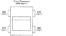
したがって、このタイヤ空気圧の検出結果に基づき、例えば図7に示す表示形態のように、メータ4に各車輪5a〜5dのタイヤ空気圧をそれぞれ表示することで、ドライバにタイヤ空気圧を伝える。そして、車輪5a〜5dのいずれかの車輪のタイヤ空気圧が低下したときには、そのタイヤ空気圧の数値が他の車輪の数値よりも低下することから、その表示を確認することでドライバはタイヤ空気圧の低下を知ることができる。また、タイヤ空気圧が閾値以下に低下したときには、タイヤ空気圧の低下の警告表示を行ったり、ブザーなどによる警報を行うことで、ドライバに対して特定車輪のタイヤ空気圧が低下していることを報知することができる。
Therefore, based on the detection result of the tire pressure, the tire pressure of each of the
以上のような方法によって車輪位置検出およびタイヤ空気圧検出を行うが、上記の手法はゼロイニシエータ方式による車輪位置検出であるため、車輪位置検出が終了するまでに或る程度の時間が掛かる。このため、車輪位置検出が終了するまでタイヤ空気圧に関する表示を何も行わなかったとすると、走行開始から暫くの期間はドライバに対してタイヤ空気圧を伝えることができなくなる。このため、本実施形態では、TPMS−ECU3が以下の処理を実行し、上記した車輪位置検出を行いつつ、車輪位置検出が終了する前には、前回の記憶内容に基づいてタイヤ空気圧の表示を行うようにしている。
Although the wheel position detection and the tire air pressure detection are performed by the method as described above, since the above method is the wheel position detection by the zero initiator method, it takes some time to complete the wheel position detection. For this reason, if no display regarding the tire pressure is performed until the wheel position detection is completed, the tire pressure cannot be transmitted to the driver for a period of time after the start of traveling. For this reason, in the present embodiment, the TPMS-
図8は、TPMS−ECU3が実行する車輪位置検出およびタイヤ空気圧表示処理のフローチャートである。この図に示す処理は、図示しないイグニッションスイッチがオンされているときに所定の制御周期毎に実行される。
FIG. 8 is a flowchart of wheel position detection and tire pressure display processing executed by the TPMS-
まず、ステップ100では、送信機2の4輪分のID(ID1〜ID4)の前回輪位置P(ID)を読み出し、P(IDn)毎にFR、FL、RR、RLを設定する。すなわち、今回の車輪位置検出の以前に前回の車輪位置検出の際に記憶されている各フレームのID情報とそれを送信した送信機2が取り付けられた車輪の位置との関係に基づいて、仮の車輪位置を設定する。なお、IDnはID1〜ID4を示しており、nは1〜4の添え字を意味している。
First, in
次に、ステップ105でフレーム(RF電波)受信処理を行ったのち、受信した場合にはステップ110で受信したフレームに格納されたID情報を確認し、自車両のIDであるか否かを判定する。ここで否定判定された場合にはステップ105に戻って再び受信するまで待機し、肯定判定されるとステップ115に進む。
Next, after receiving a frame (RF radio wave) reception process in
ステップ115では、受信したフレームに格納されたID情報と各IDnに対応する前回輪位置P(IDn)とに基づいて、前回輪位置P(IDn)がどの車輪であった送信機2からのフレームかを特定する。そして、その前回輪位置P(IDn)のタイヤ空気圧に関する情報として受信圧力データを読み込む。その後、ステップ120に進み、受信圧力データを4輪分すべて受信済みであるか否か、つまり前回輪位置P(IDn)の受信圧力データがP(ID1)〜P(ID4)のすべて揃ったか否かを判定する。そして、肯定判定されるまではステップ105からの処理を繰り返し、肯定判定されるとステップ125に進む。
In
ステップ125では、4輪分の受信圧力データに基づいて各前回輪位置P(IDn)のタイヤ空気圧を演算し、その中の最大値MAX(P(IDn))をPmaxとして記憶すると共に、その中の最小値MIN(P(IDn))をPminとして記憶する。その後、ステップ130に進み、PmaxとPminの差(Pmax−Pmin)を演算し、その差が所定の閾値ΔP以下であるか否かを判定する。これにより、各車輪5a〜5dのタイヤ空気圧の差が閾値ΔP以下であるか否かを判定できる。
In
ここで肯定判定されたときにはステップ135に進み、一旦、今回の車輪位置検出において特定する各IDnの輪位置を前回輪位置P(IDn)に設定する。そして、ステップ140に進んで受信圧力データに基づいて演算した各前回輪位置P(IDn)のタイヤ空気圧を車輪5a〜5d毎に表示する。逆に、ここで否定判定されたときにはステップ145に進み、今回の車輪位置検出において特定する各IDnの輪位置が未決定状態であることを保持する。
When an affirmative determination is made here, the routine proceeds to step 135, where the wheel position of each IDn specified in the current wheel position detection is set to the previous wheel position P (IDn). Then, the process proceeds to step 140, and the tire air pressure at each previous wheel position P (IDn) calculated based on the received pressure data is displayed for each of the
すなわち、4輪それぞれのタイヤ空気圧の最大値と最小値の差が閾値ΔP以下の場合は、各車輪5a〜5dのタイヤ空気圧の差があまり無い状態で、特定の車輪のタイヤ空気圧が大幅に低下している状態でもない。このため、仮に各車輪5a〜5dのタイヤ空気圧が誤って表示されていたとしても、ドライバにとって違和感は無い。したがって、このような場合には、前回輪位置P(IDn)を一旦今回の車輪位置検出において特定する各IDnとして仮に決定し、まずは前回輪位置としてタイヤ空気圧を表示する。こうすることで、ドライバに対してより早くからタイヤ空気圧を伝えることができる。したがって、ドライバに対して走行直後からタイヤ空気圧に問題が無いことを伝えることが可能となり、早い段階からドライビングに対する安心感を与えることが可能となる。
That is, when the difference between the maximum value and the minimum value of the tire pressure of each of the four wheels is equal to or less than the threshold value ΔP, the tire pressure of a specific wheel is greatly reduced in a state where there is not much difference between the tire pressures of the
一方、4輪それぞれのタイヤ空気圧の最大値と最小値の差が閾値ΔPを超えている場合は、特定の車輪のタイヤ空気圧が大幅に低下している状態である可能性がある。このような場合には、仮に各車輪5a〜5dのタイヤ空気圧が誤って表示されると、ドライバがタイヤ空気圧が低下した車輪を誤って認識してしまう可能性がある。このため、この場合には前回輪位置としてタイヤ空気圧を表示することを行わず、正式に車輪位置検出が終了するまでタイヤ空気圧の表示を待機するようにしている。
On the other hand, when the difference between the maximum value and the minimum value of the tire pressure of each of the four wheels exceeds the threshold value ΔP, there is a possibility that the tire pressure of a specific wheel is greatly reduced. In such a case, if the tire air pressure of each of the
続いて、ステップ150に進み、車輪位置検出処理を行う。この車輪位置検出処理では、上記の車輪位置検出の具体的な方法として説明した方法によって車輪位置検出を行う。そして、この車輪位置検出によって各フレームを送信した送信機2が車輪5a〜5dのいずれに取り付けられたものであるかを特定できたら、今回の車輪位置検出において特定した各IDnを車輪の位置と関連付けて記憶する。また、前回輪位置P(IDn)についても、今回の車輪位置検出において特定した各IDnに更新する。
Then, it progresses to step 150 and performs a wheel position detection process. In this wheel position detection process, the wheel position is detected by the method described above as a specific method of wheel position detection. Then, if it is possible to identify which of the
そして、ステップ155に進み、今回の車輪位置検出にて記憶された各フレームのID情報とそれを送信した送信機2が取り付けられた車輪の位置との関係に基づいて各IDが車輪5a〜5dのいずれの送信機2のものであるかを特定し、各車輪5a〜5dのタイヤ空気圧を特定する。これに基づき、メータ4に各車輪5a〜5dのタイヤ空気圧をそれぞれ表示することで、ドライバにタイヤ空気圧を伝える。
And it progresses to step 155 and each ID is
このようにして、図8に示した車輪位置検出およびタイヤ空気圧表示処理を終了する。その後は、各送信機2から送信されたフレームを受信するたびに、そのフレームに格納されたタイヤ空気圧に関する情報からタイヤ空気圧を演算し、今回の車輪位置検出処理の結果を利用して、受信したフレームと対応する車輪5a〜5dのタイヤ空気圧を更新していく。これにより、その後も変化するタイヤ空気圧を逐一更新して表示することが可能となる。
In this way, the wheel position detection and tire pressure display processing shown in FIG. 8 is completed. Thereafter, each time a frame transmitted from each
以上説明したように、本実施形態では、直近の過去に行った前回の車輪位置検出結果を前回輪位置として記憶している。そして、再度イグニッションスイッチがオンされたときに新たに今回の車輪位置検出結果が出るまでの間、前回輪位置を用いて各車輪5a〜5dのタイヤ空気圧表示を行っている。したがって、ドライバに対してより早くからタイヤ空気圧を伝えることができる。
As described above, in the present embodiment, the previous wheel position detection result performed in the latest past is stored as the previous wheel position. Then, when the ignition switch is turned on again, the tire pressure display of the
ただし、このように前回輪位置を用いたタイヤ空気圧表示を各車輪5a〜5dのタイヤ空気圧の差が閾値ΔP以下の場合にのみ行うようにしている。このため、特定車輪のタイヤ空気圧が低下している可能性がある場合には、正式に車輪位置検出が終了するまでタイヤ空気圧の表示を待機することになり、ドライバがタイヤ空気圧が低下した車輪を誤って認識してしまわないようにすることができる。
However, the tire air pressure display using the previous wheel position is performed only when the difference in tire air pressure between the
前回輪位置を用いたタイヤ空気圧表示を行う場合、仮にタイヤローテーションが行われていると、各車輪5a〜5dとタイヤ空気圧との関係が誤った状態で表示される誤表示になる。しかしながら、各車輪5a〜5dのタイヤ空気圧の差が閾値ΔP以下の場合にのみ前回輪位置を用いたタイヤ空気圧表示を行っているため、ほぼ4輪ともタイヤ空気圧が同圧であるため、実質誤表示とはならない。
When the tire pressure display using the previous wheel position is performed, if the tire rotation is performed, an erroneous display is displayed in which the relationship between the
さらに、前回輪位置を用いたタイヤ空気圧表示を完了した後、引き続き今回の車輪位置検出が完了した段階で、正しい車輪位置が前回輪位置と異なっていれば、正しい車輪位置に置き換えられる。このため、今回の車輪位置検出処理の結果に基づく正しい車輪位置に応じて各車輪5a〜5dのタイヤ空気圧を表示することが可能となる。この場合、各車輪5a〜5dそれぞれのタイヤ空気圧の大小関係が入れ替わることがあるが、このことはドライバに対して違和感を与えるものではない。すなわち、車両1の走行に伴って各車輪5a〜5dのタイヤ内温度が上昇していくと、それに伴ってタイヤ空気圧も上昇し、その上昇スピードは車輪毎に若干異なるため、その過程でタイヤ空気圧の大小が入れ替わることが多々ある。このため、ほぼ4輪ともタイヤ空気圧が同圧な状態からタイヤ空気圧の大小が入れ替わったとしても、ドライバに違和感を与えることはない。
Further, after the tire pressure display using the previous wheel position is completed, if the correct wheel position is different from the previous wheel position when the current wheel position detection is subsequently completed, the correct wheel position is replaced. For this reason, it becomes possible to display the tire air pressure of each
また、このように前回輪位置を用いたタイヤ空気圧表示を行うのは、本実施形態で説明したような車輪速度センサ11a〜11dの検出信号から得られる歯車情報に基づいて車輪位置検出を行う場合に適用すると特に好適である。すなわち、4輪が同じタイヤ空気圧の場合において車両1が直進し続けると、各車輪5a〜5dの動荷重半径に差が出ないため、送信機2の角度がバラツキ許容幅から外れるまでに時間が掛かる可能性がある。このため、このように車輪位置検出までに時間が掛かる可能性がある方法が採用されている場合に、より早くからタイヤ空気圧を表示できるようにすることで、よりドライバに対してドライビングに対する安心感を与えることが可能となる。
In addition, the tire pressure display using the previous wheel position is performed when the wheel position is detected based on the gear information obtained from the detection signals of the
(第2実施形態)
本発明の第2実施形態について説明する。本実施形態は、第1実施形態に対して送信機2が取り付けられた車輪位置が特定されるたびに、前回輪位置からの更新を行ってタイヤ空気圧表示が行えるようにしたものであり、その他に関しては第1実施形態と同様であるため、第1実施形態と異なる部分についてのみ説明する。
(Second Embodiment)
A second embodiment of the present invention will be described. In the present embodiment, every time the wheel position where the
上記第1実施形態では、車輪速度センサ11a〜11dの検出信号から得られる歯車情報に基づいて車輪位置検出を行っていたが、このような車輪位置検出方法では各送信機2の車輪位置の特定は4つそれぞれ独立で行われる。このため、送信機2が取り付けられた車輪が1輪ずつ特定されていくことになる(図6参照)。このような場合、車輪位置の特定が複数の車輪5a〜5dのうちの一部しか行えていない段階だとしても、特定された車輪については特定後の車輪位置でタイヤ空気圧表示を行えば良い。また、未特定の車輪については、未だの車輪間においてタイヤ空気圧の差が小さく、かつ、未特定の車輪の中に特定された車輪が含まれていなければ、前回輪位置を用いてタイヤ空気圧表示を行えば良い。
In the said 1st Embodiment, although wheel position detection was performed based on the gear information obtained from the detection signal of
例えば、4輪中1輪のみ車輪位置特定完了した場合において、他の未特定の3輪のタイヤ空気圧に差がほとんど無く、かつ、未特定の3輪が既に特定された1輪と異なっている場合には、未特定の3輪については前回輪位置を使ってタイヤ空気圧を表示すれば良い。また、4輪中2輪のみ車輪位置特定完了した場合において、他の未特定の2輪のタイヤ空気圧に差がほとんど無く、かつ、未特定の2輪が既に特定された2輪と異なっている場合には、未特定の2輪については前回輪位置を使ってタイヤ空気圧を表示すれば良い。同様に、4輪中3輪が車輪位置特定完了した場合において、他の未特定の1輪が既に特定された3輪と異なっている場合には、未特定の1輪については前回輪位置を使ってタイヤ空気圧を表示すれば良い。 For example, when only one of four wheels is located, the tire pressures of the other three unspecified wheels are almost the same, and the three unspecified wheels are different from the one already specified. In such a case, for the unspecified three wheels, the tire pressure may be displayed using the previous wheel position. In addition, when only two of the four wheels have been identified, there is almost no difference in tire pressure between the other unspecified two wheels, and the unspecified two wheels are different from the already specified two wheels. In this case, the tire pressure may be displayed using the previous wheel position for two unspecified wheels. Similarly, when three of the four wheels have completed the wheel position specification, if the other unspecified one wheel is different from the already specified three wheels, the previous wheel position is set for the unspecified one wheel. Use it to display the tire pressure.
これに基づいて、本実施形態では、以下のようにして車輪位置検出およびタイヤ空気圧表示処理を実行する。図9は、本実施形態のTPMS−ECU3が実行する車輪位置検出およびタイヤ空気圧表示処理のフローチャートである。
Based on this, in the present embodiment, wheel position detection and tire air pressure display processing are executed as follows. FIG. 9 is a flowchart of wheel position detection and tire pressure display processing executed by the TPMS-
まず、ステップ200では、全車輪分のフレーム(RF電波)を受信済みか否かを判定する。この判定は、図8のステップ100〜120と同様の手法によって行われる。ここで受信済みになるまで待機し、受信済みになるとステップ205に進む。次に、ステップ205では、4輪すべてについて車輪位置の特定が完了済みであるか否かを判定する。具体的には、後述するステップ280の車輪位置検出処理において、各IDnのうち車輪位置の特定が完了したものについて、完了済みであることが特定できるようにしてあり、それに基づいて本判定を行うようにしている。そして、完了済みでない場合にはステップ210に進む。
First, in
ステップ210では、3輪について車輪位置の特定が完了済みであるか否かを判定する。ここで肯定判定されると、ステップ215に進んで未特定の1輪の前回輪位置が既に特定されている3輪の車輪位置と異なるか否かを判定し、ここでも肯定判定されると、ステップ220に進んで特定した車輪のIDnの車輪位置以外については前回輪位置に決定する。この後、ステップ225に進み、決定している車輪位置に基づいて、各車輪5a〜5dのタイヤ空気圧表示を行う。この場合、特定されている3輪についてはその車輪のIDnが付されたフレームのタイヤ空気圧に関する情報から演算したタイヤ空気圧を表示する。そして、特定されていない1輪については残りのIDn、つまり前回輪位置P(IDn)と対応するIDnが付されたフレームのタイヤ空気圧に関する情報から演算したタイヤ空気圧を表示する。また、ステップ215で否定判定された場合には、タイヤローテーション等によって車輪位置が入れ替わっていると考えられるため、ステップ230に進んで今回の車輪位置検出において特定する各IDnの車輪位置について未決定状態を保持する。
In
また、ステップ210で否定判定された場合には、ステップ235に進み、今度は2輪について車輪位置の特定が完了済みであるか否かを判定する。ここで肯定判定されると、ステップ240に進んで未特定の2輪のタイヤ空気圧の差がΔP以下であるか否かを判定する。そして、ここで肯定判定されるとステップ245に進み、未特定の2輪の前回輪位置が既に特定されている2輪の車輪位置と異なるか否かを判定し、ここでも肯定判定されると、ステップ220に進んで特定した車輪のIDnの車輪位置以外については前回輪位置に決定する。この後、ステップ225に進み、上記と同様、決定している車輪位置に基づいて、各車輪5a〜5dのタイヤ空気圧表示を行う。なお、ステップ240で否定判定された場合には未特定のいずれかの車輪のタイヤ空気圧が低下している可能性がある。また、ステップ245で否定判定された場合には、タイヤローテーション等によって車輪位置が入れ替わっていると考えられる。これらの場合にはステップ250に進んで今回の車輪位置検出において特定する各IDnの車輪位置について未決定状態を保持する。
If a negative determination is made in
さらに、ステップ235でも否定判定された場合には、ステップ255に進み、今度は1輪について車輪位置の特定が完了済みであるか否かを判定する。ここで肯定判定されると、ステップ260に進んで未特定の3輪のタイヤ空気圧の差がΔP以下であるか否かを判定する。そして、ここで肯定判定されるとステップ265に進み、未特定の3輪の前回輪位置が既に特定されている1輪の車輪位置と異なるか否かを判定し、ここでも肯定判定されると、ステップ270に進んで特定した車輪のIDnの車輪位置以外については前回輪位置に決定する。この後、ステップ275に進み、上記ステップ225と同様、決定している車輪位置に基づいて、各車輪5a〜5dのタイヤ空気圧表示を行う。なお、ステップ260で否定判定された場合には未特定のいずれかの車輪のタイヤ空気圧が低下している可能性がある。また、ステップ265で否定判定された場合には、タイヤローテーション等によって車輪位置が入れ替わっていると考えられる。これらの場合にはステップ250に進んで今回の車輪位置検出において特定する各IDnの車輪位置について未決定状態を保持する。
Further, if a negative determination is made in
この後は、ステップ280において、車輪位置検出処理を実行し、既に実行中である場合には継続する。この車輪位置検出処理は、上記第1実施形態で車輪位置検出の具体的な方法として説明した方法によって行う。そして、この車輪位置検出によって各フレームが車輪5a〜5dのいずれに取り付けられたものであるかを特定できたら、その都度、特定した各IDnを車輪の位置と関連付けて記憶することで各IDnのうち車輪位置の特定が完了したものが特定できるようにしておく。また、前回輪位置P(IDn)についても、今回の車輪位置検出において特定した各IDnに更新する。
Thereafter, in
そして、ステップ285に進み、今回の車輪位置検出にて記憶された各フレームのID情報とそれを送信した送信機2が取り付けられた車輪の位置との関係に基づいて各IDが車輪5a〜5dのいずれの送信機2のものであるかを特定し、各車輪5a〜5dのタイヤ空気圧を特定する。これに基づき、メータ4に各車輪5a〜5dのタイヤ空気圧をそれぞれ表示することで、ドライバにタイヤ空気圧を伝える。
And it progresses to step 285 and each ID is
このように、4輪すべての車輪位置の特定が未だの段階だとしても、特定された車輪については特定後の車輪位置でタイヤ空気圧表示を行うようにしても良い。これにより、車輪位置が特定されるたびに、正確なタイヤ空気圧表示に切り替わっていくことになり、より早い段階から正確なタイヤ空気圧表示を行うことが可能となる。 As described above, even if the specification of the wheel positions of all four wheels is still in the stage, the tire pressure display may be performed at the specified wheel position for the specified wheel. Thereby, every time the wheel position is specified, the display is switched to an accurate tire pressure display, and an accurate tire pressure display can be performed from an earlier stage.
そして、前回輪位置を用いてタイヤ空気圧表示を行っていても、並行して車輪位置検出処理を行うようにしているため、パンク時には正しい車輪位置でタイヤ空気圧表示を行うことが可能となる。 Even if the tire pressure display is performed using the previous wheel position, the wheel position detection process is performed in parallel, so that the tire pressure display can be performed at the correct wheel position at the time of puncture.
(第3実施形態)
本発明の第3実施形態について説明する。本実施形態は、第2実施形態に対して送信機2の電池寿命を考慮した制御を行うものであり、その他に関しては第2実施形態と同様であるため、第2実施形態と異なる部分についてのみ説明する。
(Third embodiment)
A third embodiment of the present invention will be described. In the present embodiment, control is performed in consideration of the battery life of the
車輪5a〜5dに取り付けられる送信機2については、電池からの電力供給に基づいて作動することから、電池寿命の制約もあり、車輪位置検出を時間的な制限無く続けることが困難である。このため、一般的には車輪位置検出処理についてタイムアウトを設けて継続時間を所定時間に制限し、その後はタイヤ空気圧検出のための定期送信モードに切り替わって、車輪位置検出を行う車輪位置検出モードのときよりもフレーム送信の間隔を長く設定している。そして、タイヤ交換などが行われる可能性がある時間以上、車輪5a〜5dの回転が停止したときに再び車輪位置検出モードに切り替わり、車輪位置検出を行うようにしている。
Since the
このようなタイムアウトが設けられる場合、送信機2から送信されたフレームに基づいて車輪位置検出を行っても、全車輪の特定に至らないこともあり得る。そのような場合であっても、1輪または2輪の車輪位置を特定できている場合には、次のようにタイヤローテーションが行われていないと推測し、タイムアウト時に前回輪位置を用いてタイヤ空気圧表示を行わせるようにしても良い。
When such a timeout is provided, even if wheel position detection is performed based on the frame transmitted from the
例えば、4輪中1輪のみ車輪位置特定完了した場合において、他の未特定の3輪のタイヤ空気圧の差が大きい場合には、第2実施形態のようにタイヤ空気圧に差が無いという理由に基づいて前回輪位置を用いることはできない。しかしながら、特定完了したIDnについて、前回輪位置と変更が無い場合には、タイヤローテーションが行われていないと推測できる。このため、この場合には、タイムアウト後に、未特定の車輪については前回輪位置を用いてタイヤ空気圧表示を行うようにすることができる。 For example, when only one of the four wheels has been identified, if there is a large difference in tire pressure between the other three unspecified wheels, there is no difference in tire pressure as in the second embodiment. Based on the previous wheel position cannot be used. However, it can be inferred that tire rotation has not been performed for the IDn that has been specified and has been changed from the previous wheel position. For this reason, in this case, after the time-out, the tire pressure display can be performed for the unspecified wheel using the previous wheel position.
また、4輪中2輪のみ車輪位置特定完了した場合において、他の未特定の2輪のタイヤ空気圧の差が大きい場合にも、同様に、タイヤ空気圧に差が無いという理由に基づいて前回輪位置を用いることはできない。しかしながら、特定完了したIDnについて、前回輪位置と変更が無い場合には、タイヤローテーションが行われていないと推測できる。このため、この場合には、タイムアウト後に、未特定の車輪については前回輪位置を用いてタイヤ空気圧表示を行うようにすることができる。 In addition, when only two of the four wheels have been identified, the difference between the tire pressures of the other two unspecified wheels is large, and the previous wheel is also based on the reason that there is no difference in tire pressure. The position cannot be used. However, it can be inferred that tire rotation has not been performed for the IDn that has been specified and has been changed from the previous wheel position. For this reason, in this case, after the time-out, the tire pressure display can be performed for the unspecified wheel using the previous wheel position.
ただし、このようにタイムアウト後にも、未特定の車輪について前回輪位置を用いる場合、“推測”が含まれる。このため、車輪5a〜5dのいずれかについてパンクによるタイヤ空気圧低下が起こったときに、その車輪の送信機2が車輪位置検出モードに切り替わるようにしておき、TPMS−ECU3で再び車輪位置検出処理が実行されるようにすると好ましい。この場合、パンクした車輪については、パンクにより空気が減少し、動荷重半径が変化するため、車輪速度センサ11a〜11dの検出信号に基づく歯位置のデータの変化が顕著に発生する。したがって、比較的短時間でパンクが生じた車輪位置を正確に再認識することが可能となる。
However, “estimate” is included when the previous wheel position is used for an unspecified wheel even after a timeout. For this reason, when the tire pressure drop due to puncture occurs in any of the
(他の実施形態)
上記第1実施形態では、車輪速度センサ11a〜11dの検出信号から得られる歯車情報に基づいて車輪位置検出を行う場合について説明したが、前回輪位置を用いてタイヤ空気圧表示を行うことは、他の車輪位置検出の方法が用いられる場合にも適用できる。例えば、特許文献1に記載の方法のように、送信機に2軸の加速度センサを備えると共に、受信機にて送信機から送信されたフレームを受信したときの受信強度を測定し、これらに基づいて送信機がいずれの車輪に取り付けられているかを検出する場合にも適用できる。また、特許文献2に記載の方法のように、各車輪の近傍にRFアンテナを搭載し、受信されたフレームのうち最も受信強度の強いフレームを送信してきた送信機がそのRFアンテナに最も近い車輪に取り付けられたものであると検出する場合にも適用できる。また、特許文献3に記載の方法のように、各車輪に装着された送信機から送られる信号のRSSI値の分布に基づいて車輪位置を検出する場合にも適用できる。
(Other embodiments)
In the first embodiment, the case where the wheel position detection is performed based on the gear information obtained from the detection signals of the
上記実施形態では、フレームの受信タイミング毎にバラツキ許容幅を変更し、徐々にバラツキ許容幅が狭くなるようにしているが、歯位置を中心として設定されるバラツキ許容幅については一定としている。この配置を中心として設定されるバラツキ許容幅についても変更可能である。例えば、歯位置のバラツキは、車速が大きいほど大きくなる可能性がある。このため、車速が大きくなるほどバラツキ許容幅を大きくすることで、より的確なバラツキ許容幅を設定できる。また、加速度センサ22で加速度検出を行うときのサンプリング周期が長いほど、加速度センサ22の角度が所定角度になったときのタイミングの検出精度が落ちることから、それに応じてバラツキ許容幅を変更することで、より的確なバラツキ許容幅を設定できる。その場合、送信機2側でサンプリング周期などを把握していることから、送信機2が送信するフレーム内にバラツキ許容幅の大きさを決めるデータを含めて送信するようにすることができる。
In the above-described embodiment, the variation allowable width is changed at each frame reception timing so that the variation allowable width is gradually narrowed. However, the variation allowable width set around the tooth position is constant. The variation allowable width set around this arrangement can also be changed. For example, the variation in the tooth position may increase as the vehicle speed increases. For this reason, it is possible to set a more accurate variation allowable width by increasing the variation allowable width as the vehicle speed increases. In addition, the longer the sampling period when the
また、上記実施形態では、歯車情報に基づいて車輪位置特定を行う際に、歯位置に基づいてバラツキ許容幅を設定し、その範囲外であるか否かに基づいて車輪位置特定を行っている。そして、前回のバラツキ許容幅と今回のバラツキ許容幅とが重なる部分を新たなバラツキ許容幅として設定することでバラツキ許容幅を狭くしていっている。これにより、より短期間で車輪位置特定を行うことが可能となるが、バラツキ許容幅を狭くしなくても、上記のように正確にフレームの受信タイミングのときの歯位置を得ることで、より短時間で正確な車輪位置の特定を行うことが可能となる。さらに、歯位置のバラツキ許容幅を利用して車輪位置特定を行うようにしたが、複数回のフレーム送信時の歯位置の標準偏差などに基づいて車輪位置特定を行う場合であっても、送信角度をフレーム送信毎にずらすことで、上記と同様の効果が得られる。 Moreover, in the said embodiment, when performing wheel position specification based on gear information, the variation tolerance width | variety is set based on a tooth position, and wheel position specification is performed based on whether it is out of the range. . Then, by setting a portion where the previous variation allowable width and the current variation allowable width overlap as a new variation allowable width, the variation allowable width is narrowed. This makes it possible to identify the wheel position in a shorter period of time, but by obtaining the tooth position at the frame reception timing accurately as described above without reducing the variation allowable width, It is possible to accurately identify the wheel position in a short time. Furthermore, although the wheel position specification is performed using the tolerance width of the tooth position, the transmission is performed even when the wheel position specification is performed based on the standard deviation of the tooth position at the time of multiple frame transmissions. By shifting the angle for each frame transmission, the same effect as described above can be obtained.
また、上記実施形態では、フレーム送信を行う角度として、角度が0°の位置を各車輪5a〜5dの中心軸を中心として加速度センサ22が上方位置に位置しているときとしている。しかしながら、これは単なる一例であり、車輪の周方向の任意の位置を角度0°とすればよい。
Moreover, in the said embodiment, it is set as the time when the
上記実施形態では、TPMS−ECU3がブレーキECU10から歯車情報を取得するようにしている。しかしながら、TPMS−ECU3が歯車情報として歯車の歯のエッジ数もしくは歯数を取得できればよいことから、他のECUから取得しても良いし、車輪速度センサ11a〜11dの検出信号を入力し、その検出信号から歯車の歯のエッジ数もしくは歯数を取得するようにしても良い。特に、上記実施形態では、TPMS−ECU3とブレーキECU10を別々のECUで構成する場合について説明したが、これらが一体化された単独のECUで構成される場合もあり得る。その場合には、そのECUが直接車輪速度センサ11a〜11dの検出信号を入力し、その検出信号から歯車の歯のエッジ数もしくは歯数を所定周期毎に演算することで取得することになる。
In the above embodiment, the TPMS-
また、上記実施形態では、4つの車輪5a〜5dが備えられた車両1に対して適用された車輪位置検出機能を備えたタイヤ空気圧検出装置について説明したが、さらに車輪数が多い車両についても、同様に本発明を適用することができる。
Moreover, although the said embodiment demonstrated the tire pressure detection apparatus provided with the wheel position detection function applied with respect to the
なお、本発明では、車輪速度センサ11a〜11dにより車輪5a〜5dの回転に連動して回転させられる歯車の歯の通過を検出できれば良い。このため、歯車としては、外周面が導体とされた歯の部分と歯の間に位置する部分が交互に繰り返される磁気抵抗の異なる構造であれば良い。つまり、外縁部が凹凸とされることで外周面が導体となる凸部と非導体となる空間で構成された一般的なもののみではなく、例えば外周面が導体となる部分と非導体となる絶縁体で構成されたロータスイッチ等も含まれる(例えば特開平10−048233号公報参照)。
In the present invention, it is only necessary that the
1 車両
2 送信機
3 TPMS−ECU(受信機)
4 メータ(表示器)
5(5a〜5d) 車輪
6 車体
10 ブレーキECU
11a〜11d 車輪速度センサ
12a〜12d 歯車
21 センシング部
22 加速度センサ
23 マイクロコンピュータ
24 送信回路
25 送信アンテナ
31 受信アンテナ
32 受信回路
33 マイクロコンピュータ
1
4 Meter (display)
5 (5a-5d)
11a to 11d
Claims (2)
前記複数の車輪それぞれに設けられ、該複数の車輪それぞれのタイヤ空気圧を検出すると共に、該タイヤ空気圧に関する情報を固有の識別情報と共に格納したフレームを作成して送信する第1制御部(23)を有する送信機(2)と、
前記車体側に設けられ、受信アンテナ(31)を介して前記送信機から送信されたフレームを受信することで、前記フレームを送信してきた前記送信機が前記複数の車輪のいずれに取り付けられたものであるかという車輪位置を特定し、前記送信機の識別情報を特定された前記車輪位置と対応づけて記憶する車輪位置検出処理を行うと共に、該車輪位置検出処理によって記憶された前記識別情報と前記車輪位置との関係に基づいて、車輪を特定した形態で、前記フレームに格納されたタイヤ空気圧に関する情報に示されるタイヤ空気圧を表示器(4)に表示させる第2制御部(33)を有する受信機(3)とを備えたタイヤ空気圧検出装置であって、
前記第2制御部は、今回の車輪位置検出が完了する前には、前記複数の車輪それぞれの送信機から送信されたフレームに格納された空気圧に関する情報に示される各車輪のタイヤ空気圧の差が閾値(ΔP)以下であれば、前回の車輪位置検出によって特定され記憶された前記識別情報と前記車輪位置との関係によって示される前回輪位置を仮の車輪位置として、前記タイヤ空気圧の表示を行わせることを特徴とするタイヤ空気圧検出装置。 Applied to a vehicle (1) to which a plurality of wheels (5a to 5d) equipped with tires are attached to a vehicle body (6);
A first control unit (23) that is provided on each of the plurality of wheels, detects a tire air pressure of each of the plurality of wheels, and creates and transmits a frame storing information related to the tire air pressure together with unique identification information; Having a transmitter (2),
The transmitter, which is provided on the vehicle body side and receives the frame transmitted from the transmitter via the receiving antenna (31), is attached to any of the plurality of wheels. The wheel position detection process is performed, and the identification information stored by the wheel position detection process is stored in the wheel position detection process. A second control unit (33) for displaying the tire pressure indicated by the information on the tire pressure stored in the frame in a form specifying the wheel based on the relationship with the wheel position on the display (4). A tire pressure detecting device comprising a receiver (3),
Before the wheel position detection of this time is completed, the second control unit detects a difference in tire air pressure of each wheel indicated in the information regarding the air pressure stored in the frame transmitted from the transmitter of each of the plurality of wheels. If it is equal to or less than the threshold value (ΔP), the tire pressure is displayed with the previous wheel position indicated by the relationship between the identification information and the wheel position specified and stored by the previous wheel position detection as a temporary wheel position. A tire pressure detecting device.
前記送信機では、前記第1制御部は、該送信機が取り付けられた車輪の中心軸を中心とし、かつ、該車輪の周方向の任意の位置を角度0°として、前記加速度センサの検出信号に含まれる重力加速度成分に基づいて前記送信機の角度を検出すると共に、該角度が所定の送信角度になる所定のタイミングで繰り返し前記フレームを送信させ、
前記第2制御部は、前記車輪位置検出処理として、前記複数の車輪と連動して回転させられると共に導体とされた歯の部分と前記歯の間に位置する部分が交互に繰り返される磁気抵抗の異なる外周面を有する歯車(12a〜12d)の歯の通過を検出する車輪速度センサ(11a〜11d)の検出信号に基づいて、前記歯車の歯位置を示す歯車情報を取得すると共に、前記フレームの受信タイミングのときの前記歯位置に基づいてバラツキ許容幅を設定し、該バラツキ許容幅を設定した後における前記フレームの受信タイミングのときの前記歯位置が前記バラツキ許容幅の範囲外であれば、該フレームが送信された送信機の取り付けられた車輪の候補から除外していき、残った車輪を前記フレームが送信された送信機の取り付けられた車輪として特定することを特徴とする請求項1に記載のタイヤ空気圧検出装置。 The transmitter has an acceleration sensor (22) that outputs a detection signal corresponding to an acceleration including a gravitational acceleration component that changes with rotation of a wheel to which the transmitter is attached,
In the transmitter, the first control unit has a detection signal of the acceleration sensor centered on a central axis of a wheel to which the transmitter is attached and an arbitrary position in the circumferential direction of the wheel is set to an angle of 0 °. Detecting the angle of the transmitter based on the gravitational acceleration component included in the frame, and repeatedly transmitting the frame at a predetermined timing when the angle becomes a predetermined transmission angle,
In the wheel position detection process, the second control unit is rotated in conjunction with the plurality of wheels, and a tooth portion which is a conductor and a portion located between the teeth are alternately repeated. Based on the detection signals of the wheel speed sensors (11a to 11d) that detect the passage of the teeth of the gears (12a to 12d) having different outer peripheral surfaces, the gear information indicating the tooth positions of the gears is acquired, and If the variation allowable width is set based on the tooth position at the reception timing, and the tooth position at the reception timing of the frame after setting the variation allowable width is outside the range of the variation allowable width, The frame is transmitted from the candidate wheel attached to the transmitter, and the remaining wheel is the wheel attached to the transmitter to which the frame is transmitted. The tire air pressure detecting device according to claim 1, wherein the identifying Te.
Priority Applications (3)
| Application Number | Priority Date | Filing Date | Title |
|---|---|---|---|
| JP2012037597A JP5803733B2 (en) | 2012-02-23 | 2012-02-23 | Tire pressure detection device with wheel position detection function |
| DE102013101681.2A DE102013101681B4 (en) | 2012-02-23 | 2013-02-20 | Tire pressure sensing device with wheel position sensing function |
| US13/772,878 US8723662B2 (en) | 2012-02-23 | 2013-02-21 | Tire pressure detecting apparatus having wheel position detection function |
Applications Claiming Priority (1)
| Application Number | Priority Date | Filing Date | Title |
|---|---|---|---|
| JP2012037597A JP5803733B2 (en) | 2012-02-23 | 2012-02-23 | Tire pressure detection device with wheel position detection function |
Publications (2)
| Publication Number | Publication Date |
|---|---|
| JP2013173384A JP2013173384A (en) | 2013-09-05 |
| JP5803733B2 true JP5803733B2 (en) | 2015-11-04 |
Family
ID=48950919
Family Applications (1)
| Application Number | Title | Priority Date | Filing Date |
|---|---|---|---|
| JP2012037597A Expired - Fee Related JP5803733B2 (en) | 2012-02-23 | 2012-02-23 | Tire pressure detection device with wheel position detection function |
Country Status (3)
| Country | Link |
|---|---|
| US (1) | US8723662B2 (en) |
| JP (1) | JP5803733B2 (en) |
| DE (1) | DE102013101681B4 (en) |
Families Citing this family (14)
| Publication number | Priority date | Publication date | Assignee | Title |
|---|---|---|---|---|
| DE102011004561A1 (en) * | 2011-02-23 | 2012-08-23 | Continental Automotive Gmbh | A method of operating a tire pressure monitoring system for a motor vehicle, tire pressure monitoring system and motor vehicle |
| JP5853402B2 (en) * | 2011-04-25 | 2016-02-09 | 日産自動車株式会社 | Tire pressure monitoring device |
| JP5585596B2 (en) * | 2012-01-18 | 2014-09-10 | 株式会社デンソー | Wheel position detecting device and tire air pressure detecting device having the same |
| JP2013256157A (en) * | 2012-06-11 | 2013-12-26 | Denso Corp | Wheel position detecting device and tire air pressure detecting device including the same |
| JP2015101209A (en) * | 2013-11-25 | 2015-06-04 | 株式会社東海理化電機製作所 | Tire position determination system |
| JP2015223999A (en) * | 2014-05-29 | 2015-12-14 | 太平洋工業株式会社 | Tire air pressure monitoring device |
| US9259978B2 (en) * | 2014-06-30 | 2016-02-16 | Ford Global Technologies, Llc | Automatic wheel to tire pressure sensor correlation in distributed architecture |
| JP6507675B2 (en) * | 2015-01-28 | 2019-05-08 | 株式会社デンソー | Wheel position detection device and tire pressure detection system provided with the same |
| JP6147919B1 (en) * | 2015-09-09 | 2017-06-14 | 太平洋工業株式会社 | Tire condition detecting device and wheel position specifying device |
| JP6451588B2 (en) * | 2015-10-20 | 2019-01-16 | 株式会社オートネットワーク技術研究所 | Tire pressure monitoring system, detection device and monitoring device |
| GB2567888B (en) * | 2017-10-31 | 2020-09-30 | Schrader Electronics Ltd | Tire sensor location method and apparatus |
| JP6831001B2 (en) * | 2017-12-05 | 2021-02-17 | 太平洋工業株式会社 | Transmitter and tire condition monitoring device |
| CN113561712B (en) * | 2021-08-16 | 2023-06-09 | 保隆霍富(上海)电子有限公司 | Tire self-positioning system and positioning method thereof |
| CN115302991B (en) * | 2022-09-01 | 2023-10-13 | 万通智控科技股份有限公司 | Tire pressure sensor self-positioning method and device |
Family Cites Families (14)
| Publication number | Priority date | Publication date | Assignee | Title |
|---|---|---|---|---|
| EP0861160B1 (en) | 1995-11-17 | 2000-04-05 | Beru AG | Method of allocating transmitters to receiving antennas in tyre-pressure monitoring systems |
| JPH1048233A (en) | 1996-08-06 | 1998-02-20 | Denso Corp | Rotation detection device |
| US6489888B1 (en) | 2001-06-29 | 2002-12-03 | Johnson Controls Technology Company | Using signal strength to identify tire position |
| JP2003237328A (en) * | 2002-02-19 | 2003-08-27 | Pacific Ind Co Ltd | Tire condition monitor, and transmitter of tire condition monitor |
| US7010968B2 (en) * | 2002-04-18 | 2006-03-14 | Schrader Bridgeport International, Inc. | Determination of wheel sensor position using a wireless solution |
| JP3661670B2 (en) * | 2002-08-26 | 2005-06-15 | 株式会社デンソー | Tire pressure monitoring system, tire pressure monitoring device, and tire pressure monitoring program |
| FR2844748B1 (en) | 2002-09-25 | 2004-11-26 | Johnson Contr Automotive Elect | TIRE PRESSURE MONITORING SYSTEM FOR A MOTOR VEHICLE |
| CN1298555C (en) * | 2003-01-22 | 2007-02-07 | 日产自动车株式会社 | Tire pressure monitoring apparatus and process |
| FR2869839B1 (en) | 2004-05-04 | 2006-07-07 | Johnson Controls Tech Co | SYSTEM FOR MONITORING TIRE PRESSURE OF WHEELS OF A MOTOR VEHICLE |
| JP2006062516A (en) * | 2004-08-26 | 2006-03-09 | Pacific Ind Co Ltd | Tire condition monitoring device, transmission device, and receiving device |
| DE102008049046A1 (en) | 2008-09-26 | 2010-04-08 | Continental Automotive Gmbh | Method, sensor, detector and system for locating at least one wheel on a vehicle |
| JP5182030B2 (en) * | 2008-11-19 | 2013-04-10 | 日産自動車株式会社 | Tire pressure monitoring device and tire pressure monitoring method |
| WO2011038033A1 (en) | 2009-09-22 | 2011-03-31 | Schrader Electronics Ltd. | System and method for performing auto-location of a wheel in a vehicle using wheel phase angle information |
| DE102009059788B4 (en) | 2009-12-21 | 2014-03-13 | Continental Automotive Gmbh | Method and device for locating the installation positions of vehicle wheels in a motor vehicle |
-
2012
- 2012-02-23 JP JP2012037597A patent/JP5803733B2/en not_active Expired - Fee Related
-
2013
- 2013-02-20 DE DE102013101681.2A patent/DE102013101681B4/en not_active Expired - Fee Related
- 2013-02-21 US US13/772,878 patent/US8723662B2/en active Active
Also Published As
| Publication number | Publication date |
|---|---|
| JP2013173384A (en) | 2013-09-05 |
| DE102013101681B4 (en) | 2021-12-09 |
| US20130222128A1 (en) | 2013-08-29 |
| DE102013101681A1 (en) | 2013-08-29 |
| US8723662B2 (en) | 2014-05-13 |
Similar Documents
| Publication | Publication Date | Title |
|---|---|---|
| JP5803733B2 (en) | Tire pressure detection device with wheel position detection function | |
| JP5477368B2 (en) | Wheel position detecting device and tire air pressure detecting device having the same | |
| JP5585595B2 (en) | Wheel position detecting device and tire air pressure detecting device having the same | |
| JP5585596B2 (en) | Wheel position detecting device and tire air pressure detecting device having the same | |
| JP5477369B2 (en) | Wheel position detecting device and tire air pressure detecting device having the same | |
| JP5910402B2 (en) | Wheel position detecting device and tire air pressure detecting device having the same | |
| JP5585597B2 (en) | Wheel position detecting device and tire air pressure detecting device having the same | |
| JP5609860B2 (en) | Wheel position detecting device and tire air pressure detecting device having the same | |
| JP6507675B2 (en) | Wheel position detection device and tire pressure detection system provided with the same | |
| JP5803710B2 (en) | Wheel position detecting device and tire air pressure detecting device having the same | |
| JP5954006B2 (en) | Wheel position detecting device and tire air pressure detecting device having the same | |
| JP7102998B2 (en) | Wheel position detector and tire pressure monitoring system equipped with it | |
| JP5477370B2 (en) | Wheel position detecting device and tire air pressure detecting device having the same | |
| JP6372226B2 (en) | Wheel position detecting device and tire air pressure detecting device having the same | |
| JP6375970B2 (en) | Wheel position detection device and tire air pressure detection system including the same | |
| JP2014019214A (en) | Wheel position detection device, and tire air pressure detection apparatus having the same | |
| JP5810940B2 (en) | Wheel position detecting device and tire air pressure detecting device having the same | |
| JP2014013221A (en) | Wheel position detection device and tire air pressure detection device including the same | |
| WO2016121365A1 (en) | Wheel position detection device and tire pressure detection system provided with same | |
| JP5954001B2 (en) | Wheel position detecting device and tire air pressure detecting device having the same | |
| JP5810941B2 (en) | Wheel position detecting device and tire air pressure detecting device having the same | |
| CN104540692B (en) | Wheel position detecting device and possess its tire pneumatic pressure detector | |
| WO2016121366A1 (en) | Wheel position detection device and tire pressure detection system provided with same |
Legal Events
| Date | Code | Title | Description |
|---|---|---|---|
| A621 | Written request for application examination |
Free format text: JAPANESE INTERMEDIATE CODE: A621 Effective date: 20140527 |
|
| A977 | Report on retrieval |
Free format text: JAPANESE INTERMEDIATE CODE: A971007 Effective date: 20141210 |
|
| A131 | Notification of reasons for refusal |
Free format text: JAPANESE INTERMEDIATE CODE: A131 Effective date: 20141216 |
|
| A521 | Request for written amendment filed |
Free format text: JAPANESE INTERMEDIATE CODE: A523 Effective date: 20150210 |
|
| TRDD | Decision of grant or rejection written | ||
| A01 | Written decision to grant a patent or to grant a registration (utility model) |
Free format text: JAPANESE INTERMEDIATE CODE: A01 Effective date: 20150804 |
|
| A61 | First payment of annual fees (during grant procedure) |
Free format text: JAPANESE INTERMEDIATE CODE: A61 Effective date: 20150817 |
|
| R151 | Written notification of patent or utility model registration |
Ref document number: 5803733 Country of ref document: JP Free format text: JAPANESE INTERMEDIATE CODE: R151 |
|
| R250 | Receipt of annual fees |
Free format text: JAPANESE INTERMEDIATE CODE: R250 |
|
| R250 | Receipt of annual fees |
Free format text: JAPANESE INTERMEDIATE CODE: R250 |
|
| R250 | Receipt of annual fees |
Free format text: JAPANESE INTERMEDIATE CODE: R250 |
|
| LAPS | Cancellation because of no payment of annual fees |