JP5738132B2 - Wind speed booster - Google Patents
Wind speed booster Download PDFInfo
- Publication number
- JP5738132B2 JP5738132B2 JP2011195407A JP2011195407A JP5738132B2 JP 5738132 B2 JP5738132 B2 JP 5738132B2 JP 2011195407 A JP2011195407 A JP 2011195407A JP 2011195407 A JP2011195407 A JP 2011195407A JP 5738132 B2 JP5738132 B2 JP 5738132B2
- Authority
- JP
- Japan
- Prior art keywords
- gap
- planetary gear
- bearing
- gear
- ring
- Prior art date
- Legal status (The legal status is an assumption and is not a legal conclusion. Google has not performed a legal analysis and makes no representation as to the accuracy of the status listed.)
- Expired - Fee Related
Links
- 238000010248 power generation Methods 0.000 claims description 64
- 230000007246 mechanism Effects 0.000 claims description 56
- 230000002093 peripheral effect Effects 0.000 claims description 55
- 239000000314 lubricant Substances 0.000 claims description 34
- 230000001965 increasing effect Effects 0.000 claims description 25
- 230000000694 effects Effects 0.000 description 25
- 238000010521 absorption reaction Methods 0.000 description 9
- 238000005096 rolling process Methods 0.000 description 6
- 230000001133 acceleration Effects 0.000 description 5
- 230000005540 biological transmission Effects 0.000 description 4
- 230000015572 biosynthetic process Effects 0.000 description 4
- 238000006073 displacement reaction Methods 0.000 description 4
- 230000004048 modification Effects 0.000 description 3
- 238000012986 modification Methods 0.000 description 3
- 230000008859 change Effects 0.000 description 2
- 230000007423 decrease Effects 0.000 description 2
- 239000010687 lubricating oil Substances 0.000 description 2
- 238000004519 manufacturing process Methods 0.000 description 2
- 238000010008 shearing Methods 0.000 description 2
- 125000006850 spacer group Chemical group 0.000 description 2
- 230000009471 action Effects 0.000 description 1
- 230000004323 axial length Effects 0.000 description 1
- 230000008901 benefit Effects 0.000 description 1
- 238000007664 blowing Methods 0.000 description 1
- 238000006243 chemical reaction Methods 0.000 description 1
- 238000010276 construction Methods 0.000 description 1
- 230000008878 coupling Effects 0.000 description 1
- 238000010168 coupling process Methods 0.000 description 1
- 238000005859 coupling reaction Methods 0.000 description 1
- 230000002708 enhancing effect Effects 0.000 description 1
- 238000009434 installation Methods 0.000 description 1
- 230000000116 mitigating effect Effects 0.000 description 1
- 230000000630 rising effect Effects 0.000 description 1
- 230000035939 shock Effects 0.000 description 1
- XLYOFNOQVPJJNP-UHFFFAOYSA-N water Substances O XLYOFNOQVPJJNP-UHFFFAOYSA-N 0.000 description 1
Images


Classifications
-
- Y—GENERAL TAGGING OF NEW TECHNOLOGICAL DEVELOPMENTS; GENERAL TAGGING OF CROSS-SECTIONAL TECHNOLOGIES SPANNING OVER SEVERAL SECTIONS OF THE IPC; TECHNICAL SUBJECTS COVERED BY FORMER USPC CROSS-REFERENCE ART COLLECTIONS [XRACs] AND DIGESTS
- Y02—TECHNOLOGIES OR APPLICATIONS FOR MITIGATION OR ADAPTATION AGAINST CLIMATE CHANGE
- Y02E—REDUCTION OF GREENHOUSE GAS [GHG] EMISSIONS, RELATED TO ENERGY GENERATION, TRANSMISSION OR DISTRIBUTION
- Y02E10/00—Energy generation through renewable energy sources
- Y02E10/70—Wind energy
- Y02E10/72—Wind turbines with rotation axis in wind direction
Landscapes
- Wind Motors (AREA)
- General Details Of Gearings (AREA)
Description
本発明は、風力発電用の増速機に関する。 The present invention relates to a step-up gear for wind power generation.
例えば特許文献1に、図11〜図13に示されるような風力発電用の増速機が開示されている。
For example,
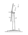
図11及び図12において、風力発電装置1は、基礎6上に立設される支柱2と、支柱2の上端に設置されるナセル3と、該ナセル3に対して回転自在に組付けられたロータヘッド4とを有している。ロータヘッド4は、複数枚(図示の例では3枚)の風車ブレード(風車翼)5が取り付けられている。ナセル3の内部において、ロータヘッド4には、増速機20及び発電機11が接続されている。
In FIG.11 and FIG.12, the
風車ブレード5に風が当たると、ロータヘッド4が回転し、該ロータヘッド4の回転が増速機20にて増速した状態で発電機11に伝達される。これにより、ロータヘッド4の(トルクはあるが)速度が遅い回転を、100倍程度の速さに増幅することができ、発電機11から効率的に発電出力を得ることができる。なお、図12に示す符号12はトランス、13はコントローラ、14はインバータ、15はインバータクーラ、16は潤滑油クーラである。
When wind hits the
前記増速機20は、図13に示すように、初段に遊星歯車機構22を備えると共に、中段及び後段に平行軸歯車機構24、26を備える。入力軸28から入力されるロータヘッド4の主軸(図示略)の回転は、計3段の歯車機構22、24、26によって増速され、出力軸30から出力される。出力軸30には、前述した発電機11が連結される。
As shown in FIG. 13, the
前記遊星歯車機構22は、入力軸28と一体化されたキャリヤ32、該キャリヤ32に固定された遊星ピン34、該遊星ピン34に回転自在に支持された遊星歯車36、該遊星歯車36が同時に噛合する内歯歯車38及び太陽歯車40から主に構成されている。この例では、太陽歯車40が遊星歯車機構22の出力軸42と一体化されると共に、内歯歯車38がケーシング44と一体化されている。
The
なお、前記遊星ピン34と遊星歯車36との間には、ころ軸受46が介在され、風車ブレード5側から入力されてくる大トルクに対応できるように配慮されている。
A roller bearing 46 is interposed between the
風力発電設備は、その耐用期間が20年前後となるように設計される。このため、増速機についても基本的に20年前後の寿命が確保されることが要求される。 The wind power generation facility is designed so that its useful life is around 20 years. For this reason, it is required that the speed increaser basically has a life of about 20 years.
しかしながら、風力発電設備は自然環境下に設置されるので(たとえガイドラインに沿った設計がなされている場合であっても)強風や突風などに起因する増速機に関するトラブルが多いというのが実状である。増速機のトラブルは、一度発生するとその被害は深刻なものとなるため、信頼性の確保が重要視されている。 However, since wind power generation facilities are installed in a natural environment (even if they are designed according to the guidelines), there are many problems with gearboxes caused by strong winds and gusts. is there. As troubles of the gearbox once occur, the damage becomes serious, so ensuring reliability is regarded as important.
一般に、増速機の信頼性を確保するにあたって有効な対策は、要するならば、設計時に各要素の安全率(セーフティファクタ)を大きくとることである。しかし、各要素の安全率を大きくとると、当然に増速機全体が大型化して重量も大きくなり、製造コスト、建設コストの増大を招くという問題が生じる。 In general, an effective measure for ensuring the reliability of the gearbox is to increase the safety factor (safety factor) of each element when designing, if necessary. However, if the safety factor of each element is increased, the speed-up gear as a whole is naturally increased in size and weight, resulting in an increase in manufacturing cost and construction cost.
本発明は、このような問題を解消するためになされたものであって、新たに見つけた中間課題(後述)を克服することによって、小型、軽量、低コストでありながら、信頼性が高く、寿命の長い風力発電用の増速機を提供することをその本来の課題としている。 The present invention was made to solve such problems, and by overcoming a newly found intermediate problem (described later), it is small, light, and low in cost, and highly reliable. Providing a gearbox for wind power generation with a long service life is the original challenge.
本発明のある態様は、遊星歯車機構を備えた風力発電用の増速機に関する。この増速機は、遊星歯車機構の一要素を構成する歯車と、歯車を、軸受を介して回転可能に支持する支持部材と、を備える。軸受における相対回転する部位以外のいずれかの部位に、歯車、軸受、及び支持部材のうちの少なくとも2者同士を、相対的に半径方向に微小変位可能とする隙間を形成する。隙間には潤滑剤が進入する。隙間を介して対向する2つの表面のうちの少なくとも一方に凹部を設けた。 One embodiment of the present invention relates to a wind speed booster equipped with a planetary gear mechanism. This speed increaser is provided with the gear which comprises one element of a planetary gear mechanism, and the supporting member which supports a gear rotatably via a bearing. A gap that allows at least two of the gear, the bearing, and the support member to be relatively minutely displaced in the radial direction is formed in any part of the bearing other than the part that rotates relatively. Lubricant enters the gap. A recess was provided on at least one of the two surfaces facing each other through a gap.
本発明の前記中間課題及びその解決原理は、公知のものではないため、ここで、本発明が着目した当該中間課題とその解決原理について、詳細に説明する。 Since the intermediate problem and the solution principle of the present invention are not publicly known, the intermediate problem and the solution principle of the present invention will be described in detail here.
風力発電設備の風車ブレードには、「風速や風向が変化する風」が瞬間的に強く掛かることがある。例えば、強い突風が風車ブレードに掛かると、増速機の各要素には瞬間的に強い加速トルクが掛かる。しかしながら、増速機の先には高速で回転する発電機が負荷として連結されているため、増速機の各要素は、慣性によりこの加速トルクに瞬時に追随して回転速度を増大させることができない。結果として、加速トルクの立ち上りが急峻の場合は、各要素にこの急峻に立ち上がる加速トルクが、(恰も静止している各要素に対して掛かるように)瞬間的にそっくり掛かってしまうことになる。 A wind turbine blade of a wind power generation facility may be momentarily strongly subjected to “wind changing in wind speed or direction”. For example, when a strong gust is applied to the windmill blade, a strong acceleration torque is momentarily applied to each element of the speed increaser. However, since a generator that rotates at high speed is connected as a load at the tip of the speed increaser, each element of the speed increaser can instantaneously follow this acceleration torque due to inertia and increase the rotation speed. Can not. As a result, when the acceleration torque rises steeply, the acceleration torque rising steeply is applied to each element instantaneously (as if applied to each stationary element).
また、例えば風向きが激しく変化するような悪天候の場合、「突然の逆風」等によって風車ブレードの逆側から風が掛かったりすることがある。すると、該風車ブレードの回転速度が瞬間的に大きく落ち込むという現象が発生する。この場合、増速機の各要素には、入力軸側から強い減速トルクが掛かる。しかし、(加速トルクが掛かるときと異なり)強い減速トルクが突然掛かるときは、たとえ風車ブレードの回転方向は逆にはならなくても、それまで各歯車の歯面間に形成されていたバックラッシの形成方向が反転してしまう現象が発生する。これは、入力軸が「駆動力を付与する状態」から、「制動力を付与する状態」に変化するためである。バックラッシが反転するときは、各歯車の歯面同士が直接ぶつかるため、歯面(この場合通常駆動時と逆側の面)に強い衝撃が加わると考えられる。この状態から、当該「突然の逆風」が止んで再加速するときに歯面のバックラッシは再び反転する。このため、結局、天候が荒れていて風が巻いていると、このような状況が発生するごとに、歯面同士の衝突が繰り返され、各歯面には両側から頻繁に衝撃が掛かってしまうことになる。 Further, for example, in the case of bad weather where the wind direction changes drastically, wind may be applied from the opposite side of the windmill blade due to “sudden headwind” or the like. As a result, a phenomenon occurs in which the rotational speed of the wind turbine blade drops momentarily. In this case, a strong deceleration torque is applied to each element of the speed increaser from the input shaft side. However, when a strong deceleration torque is suddenly applied (unlike acceleration torque is applied), even if the rotation direction of the windmill blade is not reversed, the backlash that has been formed between the tooth surfaces of each gear until then is reduced. A phenomenon that the formation direction is reversed occurs. This is because the input shaft changes from “a state in which a driving force is applied” to “a state in which a braking force is applied”. When the backlash is reversed, the tooth surfaces of the gears directly collide with each other, so that it is considered that a strong impact is applied to the tooth surface (in this case, the surface opposite to that during normal driving). From this state, when the “sudden headwind” stops and accelerates again, the backlash of the tooth surface reverses again. For this reason, after all, when the weather is rough and the wind is rolling, every time such a situation occurs, the collision between the tooth surfaces is repeated, and each tooth surface is frequently impacted from both sides. It will be.
本発明は、風力発電用の増速機のトラブルには、強風時に連続的に掛かる大きなトルクだけでなく、むしろ、このような「風速や風向の急変」に起因して、増速機の各要素に瞬間的に(ピーク的に)発生する強い負荷あるいは衝撃が大きく影響していると推察し、こうした強い瞬間的な負荷あるいは衝撃を緩和することを「中間課題」として捉え、この中間課題を克服することによって、上記本来の課題を解決するという発想で創案された。 The present invention has not only a large torque continuously applied during strong winds, but rather a problem of wind speed gear speed increasers. It is assumed that a strong load or impact that occurs instantaneously (peak) on the element has a large effect, and mitigating such a strong instantaneous load or impact is regarded as an “intermediate task”. It was conceived with the idea of solving the above-mentioned original problems by overcoming them.
本発明では、歯車と支持部材が軸受を介して相対回転する部位以外のいずれかの部位に、潤滑剤の進入可能な「隙間」を形成するようにしている。この隙間は、歯車、軸受、及び支持部材のうちの少なくとも2者同士が、相対的に半径方向に微小変位することを許容する。 In the present invention, a “gap” into which the lubricant can enter is formed in any part other than the part where the gear and the support member rotate relative to each other via the bearing. The gap allows at least two of the gear, the bearing, and the support member to be relatively slightly displaced in the radial direction.
今、「風速や風向の急変」等に起因して、入力軸回転速度が急変すると、増速機は、本来的に瞬時にその時点で最も安定的な噛合状態を自動的に形成しようとする。このとき本発明によれば、上記隙間の存在により、結果として歯車、軸受、及び支持部材のうちの少なくとも2者同士が、相対的に半径方向に微小変位することができる。この結果、上記隙間の形成態様が変化して隙間内の潤滑剤の移動(出入り)が発生するため、同時に、該潤滑剤の移動(特に隙間から出て行こうとする移動)を妨げようとする抵抗が発生する。この抵抗により、(もし抵抗がなかったならばそのまま急峻に立ち上がってしまう)負荷や衝撃を鈍らせることができる。 Now, if the input shaft rotation speed suddenly changes due to "abrupt changes in wind speed or direction", the gearbox will inherently instantly attempt to automatically form the most stable meshing state at that moment. . At this time, according to the present invention, due to the presence of the gap, at least two of the gear, the bearing, and the support member can relatively slightly displace in the radial direction. As a result, the formation mode of the gap changes and the lubricant moves (in and out) within the gap. At the same time, the lubricant moves (especially, the movement to go out of the gap). Resistance occurs. With this resistance, it is possible to damp loads and impacts (if there is no resistance, it will rise sharply as it is).
本発明に係る風力発電用の増速機は、強風が吹きやすい地域や、風向きの安定しない地域、すなわち風の乱れが大きい地域に設置される風力発電設備に組み込まれる場合に、特に有効に機能する。 The step-up gear for wind power generation according to the present invention functions particularly effectively when incorporated in a wind power generation facility installed in an area where strong winds are easily blown or an area where the wind direction is not stable, i.e., an area where wind turbulence is large. To do.
また、隙間を介して対向する2つの表面のうちの少なくとも一方に凹部を設けることにより、隙間が保持可能な潤滑剤の量を増やすと共に潤滑剤の移動を妨げて衝撃吸収効果を高めることができる。 In addition, by providing a recess on at least one of the two surfaces facing each other through the gap, it is possible to increase the amount of lubricant that can be held by the gap and to prevent the movement of the lubricant, thereby enhancing the impact absorbing effect. .
本発明によれば、小型、軽量、低コストでありながら、信頼性の高く、寿命の長い風力発電用の増速機を得ることが可能となる。 According to the present invention, it is possible to obtain a speed-up gear for wind power generation that is small in size, light in weight, and low in cost but has high reliability and long life.
以下、図面に基づいて本発明の実施形態の一例を詳細に説明する。 Hereinafter, an example of an embodiment of the present invention will be described in detail based on the drawings.
本発明に係る増速機が組み込まれる風力発電設備の概略構成については、既に図11、図12を用いて説明したものと同様であるため、重複説明は省略し、以降、増速機自体の構成について詳細にする。 The schematic configuration of the wind power generation facility in which the speed increaser according to the present invention is incorporated is the same as that already described with reference to FIG. 11 and FIG. Details about the configuration.
図1は、本発明の第1実施形態に係る風力発電用の増速機50の主要部を示す断面図、図2は、その全体断面図である。
FIG. 1 is a cross-sectional view showing a main part of a
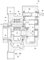
先ず、図2を参照して、この風力発電用の増速機50は、初段に遊星歯車機構52を備えると共に、中段及び後段に第1、第2平行軸歯車機構54、56を備える。入力軸58から入力される主軸(図示略)の回転は、計3段の歯車機構52、54、56によって増速され、出力軸60から出力される。出力軸60には、発電機(従来の発電機11と同様:図12参照)が連結され、所定の発電がなされる。
First, referring to FIG. 2, the
前記遊星歯車機構52は、入力軸58と一体化されたキャリヤ62、該キャリヤ62に両持ち支持された遊星ピン64、該遊星ピン64に回転自在に支持された3個(図2では1個のみ図示)の遊星歯車68、該遊星歯車68が同時に内接噛合する内歯歯車70、遊星歯車68が同時に外接噛合する太陽歯車72、及び後述のリング状の部材88から主に構成されている。この実施形態では、太陽歯車72は遊星歯車機構52の出力軸80に直接形成されており、内歯歯車70はケーシング74と一体化(固定)されている。
The
前記キャリヤ62は、円盤状の一対のキャリヤフランジ62A、62Bが連結部62Cを介して連結・対峙している構成とされ、この一対のキャリヤフランジ62A、62Bの間に前記遊星歯車68、内歯歯車70、太陽歯車72が組み込まれている。キャリヤフランジ62A、62Bは、軸受75、78によって増速機50のケーシング74に(入力軸58ごと)回転自在に支持されている。
The
前記遊星ピン64は、この一対のキャリヤフランジ62A、62Bに圧入され、両持ち支持されている。前記遊星歯車68は、該遊星ピン64によってころ軸受76およびリング状の部材88を介して回転可能に支持されている。即ち、この実施形態では、遊星歯車68が請求項1の「歯車」に相当しており、ころ軸受76が「軸受」に、遊星ピン64が「支持部材」にそれぞれ相当している。
The
ここで、図1を合わせて参照して、本実施形態における増速機の遊星歯車の付近の構成をより詳細に説明する。 Here, the configuration in the vicinity of the planetary gear of the speed increaser in the present embodiment will be described in more detail with reference to FIG.
前述したように、遊星歯車68は、ころ軸受76およびリング状の部材88を介して回転可能に(支持部材である)遊星ピン64に支持されている。この実施形態では2個のころ軸受76が軸方向に並べて配置されている。それぞれのころ軸受76は内輪76A、外輪76B、ころ(転動体)76C、及びリテーナ76Dを備えている。ころ軸受76の内輪76Aは、スペーサ82(82A〜82C)を介してキャリヤフランジ62A、62Bの間で軸方向に位置決めされている。また、ころ軸受76の外輪76Bは、ころ76C、中央のスペーサ82B、及びリテーナ76Dを介して内輪76Aに対して軸方向に位置決めされている。
As described above, the
本実施形態に係る風力発電用の増速機50では、遊星歯車68ところ軸受76(の外輪76B)との間に、リング状の部材88を介在させている。リング状の部材88の外周面88Aには、凹部すなわち周方向に伸びる複数の溝88AAが設けられる。
なお、本実施形態では、溝88AAは周方向に一周つながっているが、周方向の何カ所かで途切れた溝であってもよい。
In the step-up
In the present embodiment, the groove 88AA is connected once in the circumferential direction, but may be a groove that is interrupted at several places in the circumferential direction.
遊星歯車68は、中心孔68Aを備えている。中心孔68Aには溝68Bが形成されており、この溝68Bに止め輪84が係合している。また、リング状の部材88の軸方向の両端部にはそれぞれ、リング状の部材88の軸方向の移動を規制するための段部88B、88Cが設けられている。リング状の部材88の軸方向の一端の段部88Bは止め輪84に係止され、リング状の部材88の他端の段部88Cは遊星歯車68の対応する段部68Cに係止されている。これにより、遊星歯車68に対してリング状の部材88が軸方向に位置決めされる。
The
リング状の部材88の内周面88Dには2つの溝88DA、88DBが形成されており、これらの溝88DA、88DBのそれぞれに止め輪85A、85Bが係合している。これにより、2つのころ軸受76の外輪76Bの端部76A1、76B1に対してリング状の部材88が軸方向に位置決めされる。このように、遊星歯車68はリング状の部材88を介して軸方向に位置決めされ、該遊星歯車68の軸方向の動きが拘束されている。
Two grooves 88DA and 88DB are formed on the inner
しかし、遊星歯車68は、半径方向の微小な動きは特に拘束されていない。円周方向の動きについては、少なくともころ軸受76(の外輪76B)に対しては、全く拘束されていない。即ち、リング状の部材88の内周側には、小さな間隔の隙間S1が形成されており、外周側にはより大きな隙間S2が形成されている。より具体的には、隙間S1はリング状の部材88の内周面88Dところ軸受76の外輪76Bの外周面との間に形成され、隙間S2はリング状の部材88の外周面88Aと遊星歯車68の中心孔68Aの周面との間に形成されている。従って、この2つの隙間S1及びS2の存在により、遊星歯車68は支持部材である遊星ピン64に対して半径方向に微小変位可能である。なお、上記隙間S1、S2のうちの一方はなくてもよい。
However, the
本実施形態では、隙間S1は、ころ軸受76の外径d1に対して0.3%(3/1000)程度の大きさとなるように設定してある。隙間S1および隙間S2が、遊星歯車68ところ軸受76の外輪76Bが、相対的に半径方向に微小変位することを可能としている。本実施形態では、ころ軸受76は、支持部材である遊星ピン64と一体化された状態で組み込まれているため、遊星歯車68の方が、ころ軸受76に対して微小変位する構成とされている。
In the present embodiment, the gap S1 is set to have a size of about 0.3% (3/1000) with respect to the outer diameter d1 of the
遊星歯車68がころ軸受76に対して微小変位可能というのは、結果として、遊星歯車68が、内歯歯車70及び太陽歯車72に対して、通常のバックラッシによる円周方向の微小変位のほかに、隙間S1および隙間S2の分、更に半径方向に微小変位できることを意味する。
The
隙間S1および隙間S2内には、増速機50内の潤滑剤(潤滑油)が進入可能である。隙間S1および隙間S2内の潤滑剤の機能については、後に詳細に説明する。
The lubricant (lubricating oil) in the
次に、本実施形態に係る風力発電用の増速機50の作用を説明する。
Next, the action of the
風車ブレード5の回転は、ロータヘッド4の主軸を介して増速機50の入力軸58に伝達される。入力軸58の回転はキャリヤ62(キャリヤフランジ62A、62B)を介して遊星歯車68の公転として遊星歯車機構52に入力され、遊星歯車68、内歯歯車70、太陽歯車72の3者の相対回転により、増速された回転が太陽歯車72から遊星歯車機構52の出力軸80へと出力される。
The rotation of the
遊星歯車機構52の出力軸80の回転は、カップリング79を介して第1平行軸歯車機構54によって増幅され、第2平行軸歯車機構56によってさらに増幅された後、最終的に当該増速機50の出力軸60から取り出される。増速機50の出力軸60は、発電機11に連結されているため、結局、風車ブレード5の回転を増速した上で発電機11を回転させることができ、効率的な風力発電を行うことができる。
The rotation of the
以下、隙間S1および隙間S2の機能に着目しながら遊星歯車機構52の作用をより詳細に説明する。
Hereinafter, the operation of the
入力軸58と一体化されたキャリヤ62(キャリヤフランジ62A、62B)が回転すると、このキャリヤフランジ62A、62Bの回転に伴って遊星ピン64が遊星歯車機構52の軸心周りで公転するため、遊星歯車68が太陽歯車72に外接、内歯歯車70に内接した状態で回転する。
When the carrier 62 (
遊星ピン64と遊星歯車68との円周方向の相対回転は、専らころ軸受76のころ76Cを介して該ころ軸受76の内輪76Aと外輪76Bとが相対回転することによって実現される。これは、隙間S1、隙間S2はいずれもその間隔が極めて狭いことから、仮に、ころ軸受76の外輪76Bとリング状の部材88との間またはリング状の部材88と遊星歯車68との間もしくはその両方に円周方向の相対回転が発生しようとすると、隙間S1、隙間S2内に存在する潤滑剤に剪断応力が発生するためである。即ち、この剪断応力の発生と相俟って、遊星ピン64と遊星歯車68の円周方向の相対回転に対する抵抗は、ころ軸受76よりも隙間S1、隙間S2の方が遙かに大きくなるため、結果として、(隙間S1、隙間S2の存在に拘わらず)、ころ軸受76の外輪76Bとリング状の部材88と遊星歯車68とは、(少なくとも通常運転時は)相対回転はほとんどしない。
The relative rotation in the circumferential direction between the
一方、荒れた天候のとき、とりわけ、風向きが頻繁に変わるような強い風が吹いているとき等にあっては、風車ブレード5の回転トルクが変動(あるいは急変)するため、遊星歯車68に掛かるキャリヤ62からの公転推進力も同様に変動する。それによって内歯歯車70や太陽歯車72から受ける噛合反力も変動するため、隙間S1や隙間S2の部分にかかるラジアル荷重が変動する。その結果、遊星歯車68が遊星ピン64(具体的にはこれと一体化されているころ軸受76の外輪76B)に対して半径方向に微小変位する状態が繰り返されることになる。
On the other hand, during rough weather, especially when strong winds are blowing that frequently change the wind direction, the rotational torque of the
この微小変位により、円周方向のある部分での隙間S1の間隔が狭くなると、その部分に存在していた潤滑剤が押し潰されながら隙間S1外に押し出される。逆に、直径方向反対側では隙間S1の間隔が拡がり、隙間S1内に潤滑剤が入り込む。このとき、とりわけ隙間S1の間隔がより狭くなって隙間S1内の潤滑剤が押し潰されながら押し出されるとき、潤滑剤に強い圧縮応力と、狭い空間で強制的に移動させられることによる剪断応力が発生する。 When the gap S1 at a certain portion in the circumferential direction becomes narrow due to this minute displacement, the lubricant present in that portion is pushed out of the gap S1 while being crushed. Conversely, on the opposite side in the diameter direction, the gap S1 increases, and the lubricant enters the gap S1. At this time, in particular, when the gap S1 becomes narrower and the lubricant in the gap S1 is pushed out while being crushed, there is a strong compressive stress on the lubricant and a shear stress caused by being forced to move in a narrow space. Occur.
この圧縮応力や剪断応力の発生により、隙間S1を挟んだ2つの部材の間でピーク的な負荷が、一方側から他方側に直に(そのまま)伝達されてしまうのが防止される。即ち、リング状の部材88ところ軸受76の外輪76Bとの間で、もし隙間S1がなかったならば、そのまま急峻に大きく立ち上がって急峻に低下するような衝撃的なトルクの伝達が抑制される。
隙間S2についても同様であり、遊星歯車68とリング状の部材88との間で、もし隙間S2がなかったならば、そのまま急峻に大きく立ち上がって急峻に低下するような衝撃的なトルクの伝達が抑制される。
Generation of this compressive stress or shear stress prevents the peak load from being transmitted directly (as it is) from one side to the other side between the two members across the gap S1. That is, if there is no gap S1 between the ring-shaped
The same applies to the clearance S2, and if there is no clearance S2 between the
また、仮に、それまで隙間S1内の潤滑剤の円周方向の剪断応力の範囲内で一体的に回転していたリング状の部材88ところ軸受76の外輪76Bの間に、該剪断応力を超える円周方向の負荷がかかると、当該リング状の部材88ところ軸受76の外輪76Bとの間に「滑り」が発生するため、この新たに発生した滑りによっても、衝撃の吸収効果が発揮されると考えられる。
隙間S2についても同様であり、遊星歯車68とリング状の部材88との間の滑りによっても衝撃の吸収効果が発揮されると考えられる。
Further, if the ring-shaped
The same applies to the gap S2, and it is considered that the impact absorbing effect is also exhibited by the slip between the
更には、急峻なトルク変動の伝達が抑制されることによって、バックラッシが反転する頻度を低減することができ、仮に反転したとしても、反転時の歯面の衝撃をより低減することもできる。この効果は、風向きの安定しない地域に設置された風力発電設備の場合、現実的には小さくないと考えられる。 Furthermore, by suppressing the transmission of steep torque fluctuations, the frequency at which the backlash is reversed can be reduced, and even if it is reversed, the impact on the tooth surface during the reversal can be further reduced. This effect is not considered to be small in the case of wind power generation equipment installed in an area where the wind direction is not stable.
加えて、本実施形態に係る風力発電用の増速機50の場合、遊星歯車68が3個あり、動力伝達がなされる噛合点が計6個所存在するが、各遊星歯車68のピッチ円や公転軌道(キャリヤ62に対する遊星ピン64の位置)は、製造誤差によって必ずばらついている。また、内歯歯車70及び太陽歯車72の同軸性も必ずしも正確に確保されているわけではない。
In addition, in the case of the step-up
このため、従来の(遊星歯車機構を備えた)風力発電用の増速機の場合は、ある「特定の噛合点」にのみ、伝達トルクの負荷が強く掛かり易いという傾向があった。言うまでもなく、伝達トルクの負荷を特定の噛合点でのみ強く受けると、当該特定の噛合点でのダメージはより増強されてしまうが、この影響は、急峻に立ち上がって急峻に低下するような衝撃的なトルクが掛かった場合に一層顕著となる。 For this reason, in the case of a conventional speed increaser for wind power generation (having a planetary gear mechanism), there is a tendency that a load of transmission torque is easily applied only at a certain “specific meshing point”. Needless to say, if the transmission torque load is strongly received only at a specific meshing point, the damage at the specific meshing point is further enhanced, but this effect is a shocking effect that rises sharply and decreases sharply. This becomes more noticeable when a large torque is applied.
本実施形態に係る増速機50によれば、隙間S1や隙間S2の存在により、3個の遊星歯車68が、それぞれ内歯歯車70及び太陽歯車72に対して半径方向に微小変位できるため、リアルタイムで(瞬時に)その時点で最も安定的な噛合状態を自動的に且つより容易に形成できるようになるという効果も得られる。この安定的な噛合状態を自動的に形成できる機能は、衝撃的なトルクが掛かったときだけでなく、風向きがそれほど急に変化しないときにも常に維持されるため、より低周波数領域の変動成分の吸収にも寄与すると考えられる。
According to the
結果として、隙間S1、隙間S2と該隙間S1、隙間S2内の潤滑剤の存在により、風車ブレード5から発電機11に至るエネルギの総量はほぼ同一でありながら、特に、各要素に加わる負荷のピーク値を低減し、瞬間的な過大負荷や衝撃の発生を低減することができるようになる。この結果、風車ブレード5から入力されてくるトルクを、より安定的に伝達することが可能となり、増速機の寿命を大きく伸ばすことができる。
As a result, the total amount of energy from the
さらに、本実施形態では、リング状の部材88自体が、遊星ピン64(及びこれと一体化されたころ軸受76の外輪76B)に対して半径方向に微小変位可能であり、且つ、このリング状の部材88に対して遊星歯車68が半径方向に微小変位可能な構成とされているため、変動成分を良好に吸収可能な周波数領域をより拡大することができる。
Furthermore, in the present embodiment, the ring-shaped
また、本実施形態では、隙間S2を形成するリング状の部材88の外周面88Aに複数の溝88AAを設けたので、隙間S2に収容可能な潤滑剤の量を増やすことができる。また、溝88AAの存在により外周面88Aの濡れ性が上がり、潤滑剤の移動を妨げようとする抵抗が大きくなる。その結果、衝撃吸収効果を高めることができる。
In the present embodiment, since the plurality of grooves 88AA are provided on the outer
なお、リング状の部材88の外周面88Aに代えて、またはそれに加えて、遊星歯車68の中心孔68Aの周面に凹部を設けてもよい。
Instead of or in addition to the outer
なお、変動吸収を意図する周波数領域によっては、支持部材である遊星ピン64ところ軸受76(の内輪76A)との間に、隙間S3(図1にて想像線にて図示)を追加的に形成するのは有効である。
Depending on the frequency region intended to absorb fluctuations, a clearance S3 (illustrated by an imaginary line in FIG. 1) is additionally formed between the
さらには、このようなリング状の部材88を、遊星歯車68ところ軸受76の外輪76Bとの間に代えて、あるいは遊星歯車68ところ軸受76の外輪76Bとの間に加えて、ころ軸受76の内輪76Aと遊星ピン64の間に配置するようにしてもよい。
Further, such a ring-shaped
隙間S1の大きさも隙間S1の内径(上記実施形態ではころ軸受76の外輪76Bの外径)の3/1000に限定されない。隙間の形成位置、形成個数、あるいは大きさ(間隔)を変更すると、微小変位できる部材の慣性質量や変位の態様が異なってくるため、変動(負荷変動)を良好に吸収できる領域の周波数成分を調整することができる。このため、風力発電設備を設置する地域において実際に吹く風の性質を考慮して適宜に設定するとよい。
The size of the gap S1 is not limited to 3/1000 of the inner diameter of the gap S1 (in the above embodiment, the outer diameter of the
図3は、本発明の第2実施形態に係る風力発電用の増速機91の主要部を示す断面図である。
FIG. 3 is a cross-sectional view showing a main part of a
風力発電用の増速機91では、遊星歯車68ところ軸受76(の外輪76B)との間に、リング状の部材100を介在させている。リング状の部材100の内周面100Aには、凹部すなわち周方向に伸びる複数の溝100AAが設けられる。
In the step-up
その他の構成は、第1実施形態と同様であるため、図3の中で第1実施形態と同一または機能的に類似する部分に同一の符号を付すにとどめ、重複説明を省略する。 Since the other configuration is the same as that of the first embodiment, the same reference numerals are given to the same or functionally similar parts as in the first embodiment in FIG.
本実施形態に係る風力発電用の増速機91によると、第1実施形態に係る風力発電用の増速機50と同様の作用効果が奏される。特に、本実施形態では、隙間S1を形成するリング状の部材100の内周面100Aに複数の溝100AAを設けたので、隙間S1に収容可能な潤滑剤の量を増やすことができる。また、溝100AAの存在により内周面100Aの濡れ性が上がり、潤滑剤の移動を妨げようとする抵抗が大きくなる。その結果、衝撃吸収効果を高めることができる。
According to the
なお、リング状の部材100の内周面100Aに代えて、またはそれに加えて、ころ軸受76の外輪76Bの外周面に凹部を設けてもよい。
Instead of or in addition to the inner
図4は、本発明の第3実施形態に係る風力発電用の増速機120の主要部を示す断面図である。
FIG. 4 is a cross-sectional view showing a main part of a
風力発電用の増速機120では、遊星歯車68ところ軸受76(の外輪76B)との間に、リング状の部材122を介在させている。リング状の部材122の内周面122Aおよび外周面122Bにはそれぞれ、凹部すなわち周方向に伸びる複数の溝122AA、122BBが設けられる。内周面122Aの溝122AAと外周面122Bの溝122BBとは軸方向の間隔すなわち幅が異なる。
In the step-up
その他の構成は、第1実施形態と同様であるため、図4の中で第1実施形態と同一または機能的に類似する部分に同一の符号を付すにとどめ、重複説明を省略する。 Since the other configuration is the same as that of the first embodiment, the same reference numerals are given to the same or functionally similar parts as in the first embodiment in FIG.
本実施形態に係る風力発電用の増速機91によると、第1実施形態に係る風力発電用の増速機50と同様の作用効果が奏される。特に、本実施形態では、隙間S1を形成するリング状の部材122の内周面122Aに複数の溝122AAを設け、かつ、隙間S2を形成するリング状の部材122の外周面122Bに複数の溝122BBを設けたので、隙間S1および隙間S2のそれぞれに収容可能な潤滑剤の量を増やすことができる。また、隙間S1および隙間S2のそれぞれについて、溝122AA、122BBの存在により内周面122A、外周面122Bの濡れ性が上がり、潤滑剤の移動を妨げようとする抵抗が大きくなる。その結果、第1実施形態および第2実施形態の場合よりも衝撃吸収効果を高めることができる。
According to the
なお、リング状の部材122の内周面122Aに代えて、またはそれに加えて、ころ軸受76の外輪76Bの外周面に凹部を設けてもよい。また、リング状の部材122の外周面122Bに代えて、またはそれに加えて、遊星歯車68の中心孔68Aの周面に凹部を設けてもよい。
Instead of or in addition to the inner
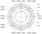
図5は、本発明の第4実施形態に係る風力発電用の増速機の主要部を示す平面図である。この増速機の構成は、リング状の部材の外周面に形成される溝の向きを除いて第1実施形態に係る増速機50の構成と同様である。図5は図1の右側から見た平面図に対応する。図5では、隙間S1の表示は省略する。
FIG. 5 is a plan view showing a main part of a step-up gear for wind power generation according to the fourth embodiment of the present invention. The configuration of the speed increaser is the same as the configuration of the
本実施形態に係る増速機では、遊星歯車68ところ軸受76(の外輪76B)との間に、リング状の部材130を介在させている。リング状の部材130の外周面130Aには、凹部すなわち軸方向に伸びる複数の溝130AAが設けられる。隙間S2には潤滑剤132が進入している。
本実施形態では、リング状の部材130の軸方向全長に亘って溝130AAが設けられる。なお、軸方向の一部のみに溝が設けられてもよい。
In the speed increaser according to the present embodiment, a ring-shaped
In the present embodiment, the groove 130AA is provided over the entire axial length of the ring-shaped
本実施形態に係る風力発電用の増速機によると、第1実施形態に係る風力発電用の増速機50と同様の作用効果が奏される。特に、本実施形態では、複数の溝130AAは軸方向に伸びるので、周方向に伸びる場合と比べて、隙間S2内の潤滑剤132が周方向に押し出されるときの抵抗が大きくなる。したがって、衝撃吸収効果をより高めることができる。
According to the step-up gear for wind power generation according to the present embodiment, the same effects as the step-up gear for
図6は、第4実施形態の変形例に係る風力発電用の増速機の主要部を示す平面図である。本変形例では、リング状の部材130の外周面130Aに加えて、遊星歯車134の中心孔134Aの周面に軸方向に伸びる複数の溝134AAが設けられる。なお、リング状の部材130の外周面130Aの溝130AAはなくてもよい。
FIG. 6 is a plan view showing a main part of a speed increasing device for wind power generation according to a modification of the fourth embodiment. In this modification, in addition to the outer
図7(a)、(b)は、本発明の第5実施形態に係る風力発電用の増速機の主要部を示す平面図および断面図である。この増速機の構成は、リング状の部材の外周面に形成される凹部の形態を除いて第1実施形態に係る増速機50の構成と同様である。図7(a)は図1の右側から見た平面図に対応する。図7(a)、(b)では、隙間S1の表示は省略する。
FIGS. 7A and 7B are a plan view and a cross-sectional view showing the main part of a gearbox for wind power generation according to the fifth embodiment of the present invention. The structure of this speed increaser is the same as that of the
本実施形態に係る増速機では、遊星歯車68ところ軸受76(の外輪76B)との間に、リング状の部材140を介在させている。リング状の部材140の外周面140Aには、凹部すなわち複数のディンプル144が設けられる。複数のディンプル144の形状、大きさ、深さ、カバー率は任意に設定できる。隙間S2には潤滑剤142が進入している。
In the speed increaser according to the present embodiment, the ring-shaped
本実施形態に係る風力発電用の増速機によると、第1実施形態に係る風力発電用の増速機50と同様の作用効果が奏される。
なお、リング状の部材140の外周面140Aに代えて、またはそれに加えて、遊星歯車68の中心孔68Aの周面に複数のディンプルを設けてもよい。
According to the step-up gear for wind power generation according to the present embodiment, the same effects as the step-up gear for
A plurality of dimples may be provided on the peripheral surface of the
図8は、本発明の第6実施形態に係る風力発電用の増速機150の主要部を示す断面図である。
FIG. 8 is a cross-sectional view showing a main part of a
第1実施形態では遊星歯車68ところ軸受76との間にリング状の部材88を介在させ、そのリング状の部材88の内周側に隙間S1を、外周側に隙間S2を設けたが、本実施形態ではリング状の部材は設けずに遊星歯車68の中心孔68Aところ軸受76の外輪76Bとの間に直接、潤滑剤が進入する隙間S4を設ける。
In the first embodiment, a ring-shaped
隙間S4を形成する遊星歯車68の中心孔68Aの周面には、凹部すなわち周方向に伸びる複数の溝68AAが設けられる。
On the peripheral surface of the
その他の構成は、第1実施形態と同様であるため、図8の中で第1実施形態と同一または機能的に類似する部分に同一の符号を付すにとどめ、重複説明を省略する。 Since the other configuration is the same as that of the first embodiment, the same reference numerals are given to the same or functionally similar portions as those of the first embodiment in FIG.
本実施形態に係る風力発電用の増速機150によると、第1実施形態に係る風力発電用の増速機50と同様の作用効果が奏される。
According to the wind
なお、遊星歯車68の中心孔68Aの周面に代えて、またはそれに加えて、ころ軸受76の外輪76Bの外周面に凹部を設けてもよい。
また、隙間S4の形成に代えて、あるいは、隙間S4の形成に加えて、ころ軸受76の内輪76Aと遊星ピン(支持部材)64との間に隙間S6(図8において想像線で図示)を形成し、その隙間S6を介して対向する面の少なくとも一方に凹部(図8において破線で図示)を設けても、同様の作用効果が得られる。
In place of or in addition to the peripheral surface of the
Further, instead of forming the gap S4 or in addition to forming the gap S4, a gap S6 (illustrated by an imaginary line in FIG. 8) is provided between the
図9は、本発明の第7実施形態に係る風力発電用の増速機160の主要部を示す断面図である。
FIG. 9 is a cross-sectional view showing a main part of a
この実施形態においては、遊星歯車83が、遊星歯車部83Aと、該遊星歯車部83Aを支持する遊星ピン部83Cとで構成されている。この構成例から明らかなように、本発明における「歯車」は、軸受を介して支持部材に回転可能に支持される部材または部材群であって歯部を有する部材または部材群、と定義されてもよい。そして、この(遊星ピン部83Cを含む)遊星歯車83が、両サイドに配置された支持部材たるキャリヤ84(一対のキャリヤフランジ84A、84B)によって該キャリヤ84に対してころ軸受86を介して回転可能に両持ち支持されている。遊星歯車83は、ころ軸受86を介してキャリヤフランジ84A、84Bと相対回転可能である。ころ軸受86は内輪86A及び外輪86B及びころ86Cを備えている。
In this embodiment, the
キャリヤ84(一対のキャリヤフランジ84A、84B)ところ軸受86(の外輪86B)との間に、潤滑剤が進入する隙間S5が形成されている。即ち、この実施形態では、(遊星ピン部83Cを含む)遊星歯車83が、本発明の「歯車」に相当し、キャリヤ84(一対のキャリヤフランジ84A、84B)が、該「歯車」を、ころ軸受86を介して回転可能に支持する「支持部材」に相当していることになる。
A gap S5 into which the lubricant enters is formed between the carrier 84 (the pair of
隙間S5を形成するキャリヤフランジ84A、84Bの内周面84A1、84B1のそれぞれには、凹部すなわち周方向に伸びる複数の溝84AA、84BBが設けられる。
Each of the inner peripheral surfaces 84A1 and 84B1 of the
この実施形態に係る構成によっても、第1実施形態と同様に、遊星歯車83が支持部材たるキャリヤ84に対して半径方向に微小変位できる。ただし、この実施形態に係る遊星歯車83は、遊星ピン部83Cを一体に含んでいるため、第1実施形態よりも微小変位する部材の慣性質量が大きい。このため、設計次第で、より低周波数の領域での変動吸収を良好に行うことができる可能性がある。
Also with the configuration according to this embodiment, the
また、この実施形態でも、隙間S5を形成するキャリヤフランジ84A、84Bの内周面84A1、84B1のそれぞれに複数の溝84AA、84BBを設けたので、隙間S5に収容可能な潤滑剤の量を増やすことができる。また、溝84AA、84BBの存在により内周面84A1、84B1の濡れ性が上がり、潤滑剤の移動を妨げようとする抵抗が大きくなる。その結果、衝撃吸収効果を高めることができる。
Also in this embodiment, since the plurality of grooves 84AA and 84BB are provided on the inner peripheral surfaces 84A1 and 84B1 of the
なお、キャリヤフランジ84A、84Bの内周面84A1、84B1に代えて、またはそれに加えて、ころ軸受86の外輪86Bの外周面に凹部を設けてもよい。
A recess may be provided on the outer peripheral surface of the outer ring 86B of the roller bearing 86 instead of or in addition to the inner peripheral surfaces 84A1 and 84B1 of the
この実施形態に対しても、隙間S5に代えて、あるいは隙間S5に加えて、ころ軸受86の内輪86Aと遊星歯車83との間に隙間S7(図9において想像線にて図示)を形成し、その隙間S7を介して対向する面の少なくとも一方に凹部(図9において破線で図示)を設けてもよい。また、このようなキャリヤ84での隙間S5(或いはS7)の形成に代えて、あるいは加えて、遊星歯車83の遊星歯車部83Aと遊星ピン部83Cとの間に隙間S8(図9において想像線にて図示)を設け、その隙間S8を介して対向する面の少なくとも一方に凹部(図9において破線で図示)を設けてもよい。また、遊星歯車部83Aと遊星ピン部83Cの間に、第1から第5実施形態のいずれかで説明されたようなリング状の部材(図示略)を配置してもよい。これにより、キャリヤ84での隙間S5(或いはS7)による変動吸収効果のほか、遊星歯車部83Aと遊星ピン部83Cの間においても、(吸収しようとする周波数成分次第では)有効な変動吸収効果が得られるようになる。なお、遊星歯車部83Aと遊星ピン部83Cは、別体ではなく、一体に形成されていてもよい。
あるいはまた、キャリヤ84(一対のキャリヤフランジ84A、84B)ところ軸受86(の外輪86B)との間に第1から第5実施形態のいずれかで説明されたようなリング状の部材(図示略)を配置してもよい。
Also in this embodiment, a gap S7 (illustrated by an imaginary line in FIG. 9) is formed between the
Alternatively, a ring-shaped member (not shown) as described in any of the first to fifth embodiments between the carrier 84 (the pair of
その他の構成は、第1実施形態と同様であるため、図9の中で先の実施形態と同一または機能的に類似する部分に同一の符号を付すにとどめ、重複説明を省略する。 Since the other configuration is the same as that of the first embodiment, the same reference numerals are given to the same or functionally similar portions as those of the previous embodiment in FIG.
第1から第7実施形態について、隙間の形成される位置や大きさ、あるいは位相が異なると、変動吸収可能な周波数領域が異なってくるため、風力発電設備の設置される地域の方の性質を考慮してより効果的な変動吸収を行うことができるようになる。 Regarding the first to seventh embodiments, if the position, size, or phase at which the gap is formed is different, the frequency region that can be absorbed and absorbed is different. Considering this, it becomes possible to perform more effective fluctuation absorption.
また、第1から第7実施形態について、潤滑剤が進入する隙間を介して対向する面の少なくとも一方に設けられる凹部が溝である場合は溝の数が多いほど、ディンプルである場合はディンプルの数が多いほど、より衝撃吸収効果を高めることができる。また隙間を介して対向する面の一方にのみ凹部が設けられる場合よりも、それらの面の両方に凹部が設けられる場合のほうが、より衝撃吸収効果を高めることができる。 Further, in the first to seventh embodiments, when the concave portion provided on at least one of the surfaces facing each other through the gap into which the lubricant enters is a groove, the greater the number of grooves, the more the dimples The greater the number, the higher the impact absorption effect. In addition, the impact absorbing effect can be further enhanced when the recesses are provided on both of the surfaces, rather than when the recesses are provided only on one of the surfaces facing each other through the gap.
なお、上記実施形態においては、遊星歯車機構として、単純遊星歯車構造の遊星歯車機構が採用されていたが、本発明における遊星歯車機構は、単純遊星歯車構造の遊星歯車機構に限定されるものではない。例えば、図10にスケルトン図示するような遊星歯車機構が特開2003−278849号公報に開示されている。 In the above embodiment, a planetary gear mechanism having a simple planetary gear structure is employed as the planetary gear mechanism. However, the planetary gear mechanism in the present invention is not limited to a planetary gear mechanism having a simple planetary gear structure. Absent. For example, a planetary gear mechanism such as a skeleton shown in FIG. 10 is disclosed in Japanese Patent Laid-Open No. 2003-278849.
この遊星歯車機構93は、太陽歯車がなく、遊星ピン部94Cと一体化された同一歯数の遊星歯車部94A、94Bを2個有し、それぞれの遊星歯車部94A、94Bと噛合すると共に異なる歯数を有する2個の内歯歯車95A、95Bを備えている。この遊星歯車機構93を風力発電用の増速機(全体は図示略)に適用する場合、2種類ある内歯歯車95A、95Bのうちの一方の内歯歯車95Aが入力軸92と連結され、キャリヤ97(必要ならば遊星歯車94を挟んで一対としてもよい)が出力軸96と連結される態様で使用することになる。
This
この遊星歯車機構93は、構造は若干複雑であるが、その分、様々な態様で増速機を設計できるというメリットがある。このため、設置空間の制約が大きい風力発電用の増速機として、主に寸法的・形状的な面で有効に利用可能である。
Although this
例えば、この遊星歯車機構93は、前述したように太陽歯車を有していないことから、中央部に大きな中空部(図示略)を形成するのが容易である。このため、入力軸92の周り(或いは内側)に何らかの制御機器やセンサ、配管等を配設する必要が生じたとき等において該中空部を有効に利用できる。また、この遊星歯車機構93は、約5倍から30倍の増速を容易に設計できるため、必要ならば、後段の平行軸歯車機構(図示略)を、1段で済ますことも可能であり、この場合、重量や軸方向寸法の縮小が可能である。
For example, since the
このような構造の遊星歯車機構93を有する風力発電用の増速機の場合、具体的には、2つの遊星歯車部94A、94Bと遊星ピン部94Cが一体化された「遊星歯車94」がその両側に存在する支持部材たるキャリヤ97に図示せぬ軸受を介して両持ち支持される構造となる。このため、本発明を図9に示された構成と類似した構成により適用することができる。
In the case of a speed increasing device for wind power generation having the
また、この遊星歯車機構93においては、2つの内歯歯車95A、95Bのうちの一方の内歯歯車95Aが軸受98を介してケーシング99に回転自在に支持される構造であるため、設計によっては、この内歯歯車95Aと軸受98と該内歯歯車95Aを支持しているケーシング99の3者間で、本発明に係る隙間を形成し、かつ、その隙間を介して対向する面の少なくとも一方に凹部を形成することも可能である。
The
換言するならば、本発明に係る「歯車」は、遊星歯車に限定されるものではなく、遊星歯車機構の構成によっては内歯歯車、あるいは太陽歯車に対しても適用可能である。 In other words, the “gear” according to the present invention is not limited to the planetary gear, and can be applied to an internal gear or a sun gear depending on the configuration of the planetary gear mechanism.
このように、遊星歯車機構には、さまざまな構成が知られており、いずれの構成の遊星歯車機構を採用する場合においても、軸受における相対回転する部位以外のいずれかの部位に、潤滑剤が進入可能であって、且つ当該特定の歯車、軸受、及び支持部材のうちの少なくとも2者同士を、相対的に半径方向に微小変位可能とする隙間を形成したものである限り、本発明の範疇に属するものであり、本発明の作用効果を相応に得ることができる。但し、好ましくは、「単純遊星歯車機構」の「遊星歯車」の支持部分に本発明を適用するのがよい。それは、構造が簡単で安価である上に、遊星歯車が公転成分と自転成分を有して内歯歯車と太陽歯車に挟まれた状態で回転する構造であるため、該遊星歯車が隙間の存在によって半径方向に微小変位できることによる効果が、非常に顕著に顕れやすいからである。なお、遊星歯車の歯車の個数は、上記実施形態では3個であったが、2個でもよく、また、4個以上でもよく、特に限定されない。 As described above, various configurations are known for the planetary gear mechanism. Even when the planetary gear mechanism having any configuration is adopted, the lubricant is applied to any portion of the bearing other than the relatively rotating portion. The scope of the present invention is not limited as long as it is capable of entering, and is formed with a gap that allows at least two of the specific gear, bearing, and support member to be relatively finely displaced in the radial direction. Therefore, the effects of the present invention can be obtained accordingly. However, it is preferable to apply the present invention to the support portion of the “planetary gear” of the “simple planetary gear mechanism”. It has a simple structure and is inexpensive, and the planetary gear has a revolution component and a rotation component and rotates while being sandwiched between an internal gear and a sun gear. This is because the effect of being able to make a minute displacement in the radial direction is very prominent. The number of planetary gears is three in the above embodiment, but may be two or four or more, and is not particularly limited.
なお、上記実施形態においては、軸受として、いずれもころ軸受が採用されていたが、本発明においては、軸受の種類は必ずしもころ軸受に限定されない。発電容量、あるいは遊星歯車機構の構成によっては、例えば、玉軸受や滑り軸受が採用されてもよい。更には、上記実施形態においては、軸受はすべて内輪及び外輪の双方を有していたが、本発明においては、隙間を形成しない側においては、内輪あるいは外輪が省略された軸受であってもよい。いずれの構造の軸受が採用される場合でも、軸受としての本来の(歯車と支持部材との間の)相対回転が行われる部位以外に、本発明に係る隙間が存在することになる。例えば、軸受として、滑り軸受が採用されている場合には、歯車と支持部材との間の通常運転時の相対回転はあくまで当該滑り軸受の部分で行われる。従って、この滑り軸受における相対回転が行われる部位以外に、本発明に係る隙間が別途存在することになる。換言するならば、「軸受における相対回転する部位」には、不可避的に隙間が存在するが、この軸受において相対回転する部位の隙間は、本発明の隙間には含まれない。「軸受における相対回転する部位の隙間」は、例えば内外輪を有する軸受であれば、内輪−転動体−外輪間の隙間であり、内外輪の一方がない場合には、内外輪のある方−転動体−転動体の転走面を構成する部材間の隙間、ということになる。 In the above embodiment, a roller bearing is employed as the bearing. However, in the present invention, the type of bearing is not necessarily limited to the roller bearing. Depending on the power generation capacity or the configuration of the planetary gear mechanism, for example, a ball bearing or a sliding bearing may be employed. Further, in the above embodiment, all the bearings have both the inner ring and the outer ring. However, in the present invention, the bearing in which the inner ring or the outer ring is omitted may be provided on the side where no gap is formed. . Even when a bearing having any structure is employed, there is a gap according to the present invention in addition to the original relative rotation (between the gear and the support member) as the bearing. For example, when a sliding bearing is employed as the bearing, relative rotation during normal operation between the gear and the support member is performed only at the sliding bearing portion. Accordingly, a gap according to the present invention is separately present in addition to the portion where the relative rotation is performed in the slide bearing. In other words, a gap is unavoidably present in the “part of relative rotation in the bearing”, but the gap of the part of relative rotation in the bearing is not included in the gap of the present invention. The “gap between the relative rotating parts of the bearing” is a gap between the inner ring, the rolling element, and the outer ring, for example, if the bearing has inner and outer rings. That is, the rolling element—the gap between the members constituting the rolling surface of the rolling element.
第1から第4実施形態および第6、第7実施形態では、隙間を介して対向する面の少なくとも一方に形成される溝は周方向または軸方向に伸びる場合について説明したが、これに限られない。例えば、溝は回転軸に対して斜めにすなわちらせん状に形成されてもよい。あるいはまた、隙間を介して対向する面の両方に溝が形成される場合は、一方の面に形成される溝が伸びる方向を他方の面に形成される溝が伸びる方向と異ならせてもよい。複数の溝やディンプルの幅や大きさ、深さを異ならせてもよいし、2面以上に形成される場合には面によって数、幅、大きさ、深さ等を異ならせてもよい。 In the first to fourth embodiments and the sixth and seventh embodiments, the groove formed on at least one of the faces facing each other through the gap has been described as extending in the circumferential direction or the axial direction. However, the present invention is not limited to this. Absent. For example, the groove may be formed obliquely with respect to the rotation axis, that is, in a spiral shape. Alternatively, when grooves are formed on both surfaces facing each other through a gap, the direction in which the grooves formed on one surface extend may be different from the direction in which the grooves formed on the other surface extend. . The widths, sizes, and depths of the plurality of grooves and dimples may be different, and when they are formed on two or more surfaces, the number, width, size, depth, and the like may be different depending on the surfaces.
1…風力発電設備
3…ナセル
4…ロータヘッド
5…風車ブレード
11…発電機
50…増速機
52…遊星歯車機構
58…入力軸
60…出力軸
62…キャリヤ
64…遊星ピン
68…遊星歯車
70…内歯歯車
72…太陽歯車
74…ケーシング
76…ころ軸受
88…リング状の部材
S1〜S8…隙間
DESCRIPTION OF
Claims (9)
前記遊星歯車機構の一要素を構成する歯車と、
前記歯車を、軸受を介して回転可能に支持する支持部材と、を備え、
前記軸受における相対回転する部位以外のいずれかの部位に、前記歯車、軸受、及び支持部材のうちの少なくとも2者同士を、相対的に半径方向に微小変位可能とする隙間を形成し、
前記隙間には潤滑剤が進入し、
前記隙間を介して対向する2つの表面のうちの少なくとも一方に凹部を設け、
前記歯車が、前記遊星歯車機構の遊星歯車であり、
該遊星歯車が、該歯車と一体的に回転する遊星ピンごと、前記支持部材としての前記遊星歯車機構のキャリヤによって該キャリヤに対して回転可能に支持されると共に、
前記軸受が外輪を備えており、
前記隙間が、該キャリヤと該軸受の外輪との間に形成されていることを特徴とする風力発電用の増速機。 In the gearbox for wind power generation equipped with a planetary gear mechanism,
A gear constituting one element of the planetary gear mechanism;
A support member that rotatably supports the gear via a bearing,
In any part of the bearing other than the relatively rotating part, a gap is formed so that at least two of the gear, the bearing, and the support member can be slightly displaced relatively in the radial direction,
Lubricant enters the gap,
A recess is provided on at least one of the two surfaces facing each other through the gap ,
The gear is a planetary gear of the planetary gear mechanism;
The planetary gear is supported by the carrier of the planetary gear mechanism as the support member together with the planetary pin that rotates integrally with the gear, and is rotatably supported by the carrier.
The bearing includes an outer ring;
A speed increasing device for wind power generation , wherein the gap is formed between the carrier and an outer ring of the bearing .
前記遊星歯車機構の一要素を構成する歯車と、
前記歯車を、軸受を介して回転可能に支持する支持部材と、を備え、
前記軸受における相対回転する部位以外のいずれかの部位に、前記歯車、軸受、及び支持部材のうちの少なくとも2者同士を、相対的に半径方向に微小変位可能とする隙間を形成し、
前記隙間には潤滑剤が進入し、
前記隙間を介して対向する2つの表面のうちの少なくとも一方に凹部を設け、
前記歯車が、前記遊星歯車機構の遊星歯車であり、
該遊星歯車が、該歯車と一体的に回転する遊星ピンごと、前記支持部材としての前記遊星歯車機構のキャリヤによって該キャリヤに対して回転可能に支持されると共に、
前記軸受が内輪を備えており、
前記隙間が、前記遊星ピンと該軸受の内輪との間に形成されていることを特徴とする風力発電用の増速機。 In the gearbox for wind power generation equipped with a planetary gear mechanism,
A gear constituting one element of the planetary gear mechanism;
A support member that rotatably supports the gear via a bearing,
In any part of the bearing other than the relatively rotating part, a gap is formed so that at least two of the gear, the bearing, and the support member can be slightly displaced relatively in the radial direction,
Lubricant enters the gap,
A recess is provided on at least one of the two surfaces facing each other through the gap ,
The gear is a planetary gear of the planetary gear mechanism;
The planetary gear is supported by the carrier of the planetary gear mechanism as the support member together with the planetary pin that rotates integrally with the gear, and is rotatably supported by the carrier.
The bearing has an inner ring;
A speed increasing device for wind power generation , wherein the gap is formed between the planetary pin and an inner ring of the bearing .
前記遊星歯車機構の一要素を構成する歯車と、
前記歯車を、軸受を介して回転可能に支持する支持部材と、を備え、
前記軸受における相対回転する部位以外のいずれかの部位に、前記歯車、軸受、及び支持部材のうちの少なくとも2者同士を、相対的に半径方向に微小変位可能とする隙間を形成し、
前記隙間には潤滑剤が進入し、
前記隙間を介して対向する2つの表面のうちの少なくとも一方に凹部を設け、
前記歯車と軸受との間に、リング状の部材が介在され、
該リング状の部材の内周側及び外周側の両方に、前記隙間が形成され、
該リング状の部材の内周面及び外周面の両方に凹部を設けたことを特徴とする風力発電用の増速機。 In the gearbox for wind power generation equipped with a planetary gear mechanism,
A gear constituting one element of the planetary gear mechanism;
A support member that rotatably supports the gear via a bearing,
In any part of the bearing other than the relatively rotating part, a gap is formed so that at least two of the gear, the bearing, and the support member can be slightly displaced relatively in the radial direction,
Lubricant enters the gap,
A recess is provided on at least one of the two surfaces facing each other through the gap ,
A ring-shaped member is interposed between the gear and the bearing,
The gap is formed on both the inner peripheral side and the outer peripheral side of the ring-shaped member,
A speed increasing device for wind power generation, characterized in that recesses are provided on both an inner peripheral surface and an outer peripheral surface of the ring-shaped member.
前記遊星歯車機構の一要素を構成する歯車と、
前記歯車を、軸受を介して回転可能に支持する支持部材と、を備え、
前記軸受における相対回転する部位以外のいずれかの部位に、前記歯車、軸受、及び支持部材のうちの少なくとも2者同士を、相対的に半径方向に微小変位可能とする隙間を形成し、
前記隙間には潤滑剤が進入し、
前記隙間を介して対向する2つの表面のうちの少なくとも一方に凹部を設け、
前記軸受と前記支持部材との間に、リング状の部材が介在され、
該リング状の部材の内周側及び外周側の両方に、前記隙間が形成され、
該リング状の部材の内周面及び外周面の両方に凹部を設けたことを特徴とする風力発電用の増速機。 In the gearbox for wind power generation equipped with a planetary gear mechanism,
A gear constituting one element of the planetary gear mechanism;
A support member that rotatably supports the gear via a bearing,
In any part of the bearing other than the relatively rotating part, a gap is formed so that at least two of the gear, the bearing, and the support member can be slightly displaced relatively in the radial direction,
Lubricant enters the gap,
A recess is provided on at least one of the two surfaces facing each other through the gap ,
A ring-shaped member is interposed between the bearing and the support member,
The gap is formed on both the inner peripheral side and the outer peripheral side of the ring-shaped member,
A speed increasing device for wind power generation, characterized in that recesses are provided on both an inner peripheral surface and an outer peripheral surface of the ring-shaped member.
前記リング状の部材を複数備えたことを特徴とする風力発電用の増速機。 In claim 3 or 4 ,
A speed increaser for wind power generation, comprising a plurality of the ring-shaped members.
前記歯車が、前記遊星歯車機構の遊星歯車であり、
該遊星歯車が、前記支持部材としての遊星ピンによって該遊星ピンに対して回転可能に支持されると共に、
前記軸受が外輪を備えており、
前記隙間が、前記歯車と該軸受の外輪との間に形成されていることを特徴とする風力発電用の増速機。 In any one of Claims 3-5 ,
The gear is a planetary gear of the planetary gear mechanism;
The planetary gear is rotatably supported with respect to the planetary pin by a planetary pin as the support member;
The bearing includes an outer ring;
A speed increasing device for wind power generation, wherein the gap is formed between the gear and an outer ring of the bearing.
前記歯車が、前記遊星歯車機構の遊星歯車であり、
該遊星歯車が、前記支持部材としての遊星ピンによって該遊星ピンに対して回転可能に支持されると共に、
前記軸受が内輪を備えており、
前記隙間が、前記遊星ピンと該軸受の内輪との間に形成されていることを特徴とする風力発電用の増速機。 In any one of Claims 3-6 ,
The gear is a planetary gear of the planetary gear mechanism;
The planetary gear is rotatably supported with respect to the planetary pin by a planetary pin as the support member;
The bearing has an inner ring;
A speed increasing device for wind power generation, wherein the gap is formed between the planetary pin and an inner ring of the bearing.
前記凹部は溝であることを特徴とする風力発電用の増速機。 In any one of Claims 1-7 ,
The speed increaser for wind power generation, wherein the recess is a groove.
前記遊星歯車機構が、単純遊星歯車機構であることを特徴とする風力発電用の増速機。 In any one of Claims 1-8 ,
A speed increasing device for wind power generation, wherein the planetary gear mechanism is a simple planetary gear mechanism.
Priority Applications (3)
| Application Number | Priority Date | Filing Date | Title |
|---|---|---|---|
| JP2011195407A JP5738132B2 (en) | 2011-09-07 | 2011-09-07 | Wind speed booster |
| CN201280041988.5A CN103765050B (en) | 2011-09-07 | 2012-09-07 | Gearbox for wind power generation |
| PCT/JP2012/072981 WO2013035865A1 (en) | 2011-09-07 | 2012-09-07 | Step-up gear for wind-powered electricity generation |
Applications Claiming Priority (1)
| Application Number | Priority Date | Filing Date | Title |
|---|---|---|---|
| JP2011195407A JP5738132B2 (en) | 2011-09-07 | 2011-09-07 | Wind speed booster |
Publications (2)
| Publication Number | Publication Date |
|---|---|
| JP2013057347A JP2013057347A (en) | 2013-03-28 |
| JP5738132B2 true JP5738132B2 (en) | 2015-06-17 |
Family
ID=48133402
Family Applications (1)
| Application Number | Title | Priority Date | Filing Date |
|---|---|---|---|
| JP2011195407A Expired - Fee Related JP5738132B2 (en) | 2011-09-07 | 2011-09-07 | Wind speed booster |
Country Status (1)
| Country | Link |
|---|---|
| JP (1) | JP5738132B2 (en) |
Family Cites Families (4)
| Publication number | Priority date | Publication date | Assignee | Title |
|---|---|---|---|---|
| JPH0545297U (en) * | 1991-11-22 | 1993-06-18 | 株式会社ハーモニツク・ドライブ・システムズ | Load distribution mechanism for planetary gear unit |
| JP2007071355A (en) * | 2005-09-09 | 2007-03-22 | Nissan Motor Co Ltd | Pinion support structure for planetary gears |
| JP2009144533A (en) * | 2007-12-11 | 2009-07-02 | Mitsubishi Heavy Ind Ltd | Wind turbine generator |
| JP5345048B2 (en) * | 2009-12-15 | 2013-11-20 | 三菱重工業株式会社 | Wind power transmission and wind power generator |
-
2011
- 2011-09-07 JP JP2011195407A patent/JP5738132B2/en not_active Expired - Fee Related
Also Published As
| Publication number | Publication date |
|---|---|
| JP2013057347A (en) | 2013-03-28 |
Similar Documents
| Publication | Publication Date | Title |
|---|---|---|
| ES2587020T3 (en) | A wind turbine with a transmission train | |
| JP5352510B2 (en) | Wind speed booster | |
| JP5654949B2 (en) | Power transmission device for wind power generation equipment | |
| JP5520247B2 (en) | Reduction device for wind power generation equipment and reduction device with output pinion | |
| WO2013035865A1 (en) | Step-up gear for wind-powered electricity generation | |
| CN102518787A (en) | Planetary transmission structure of wind power gear box | |
| CA2711631A1 (en) | Parallel gear unit for a gearbox for a wind turbine | |
| JP5877222B2 (en) | Power transmission device for wind power generation equipment | |
| JP5832206B2 (en) | Wind speed booster | |
| JP5579050B2 (en) | Reduction gear used for wind power generation equipment | |
| JP6237273B2 (en) | Joint member for wind power generator and wind power generator | |
| JP5738132B2 (en) | Wind speed booster | |
| US20150038284A1 (en) | Epicyclic gearing with a gearing housing | |
| JP5917070B2 (en) | Wind speed booster with locked train mechanism | |
| JP5836035B2 (en) | Wind speed booster | |
| WO2013038495A1 (en) | Step-up gear for wind-powered electricity generation | |
| KR101346846B1 (en) | Wind power generator | |
| JP5836036B2 (en) | Wind speed booster | |
| EP3208493B1 (en) | Drive device for driving power generator device | |
| JP2019526012A (en) | Nacelle and rotor for wind turbine and method | |
| WO2012127736A1 (en) | Speed increasing gear for wind turbine | |
| JP6138012B2 (en) | Yaw drive system for wind power generation equipment | |
| KR101074694B1 (en) | Wind turbine gearbox with rotating housing | |
| JP5676293B2 (en) | Wind speed booster | |
| US10077762B2 (en) | Power generation device and rotating portion support structure |
Legal Events
| Date | Code | Title | Description |
|---|---|---|---|
| A621 | Written request for application examination |
Free format text: JAPANESE INTERMEDIATE CODE: A621 Effective date: 20131216 |
|
| A131 | Notification of reasons for refusal |
Free format text: JAPANESE INTERMEDIATE CODE: A131 Effective date: 20140819 |
|
| A521 | Written amendment |
Free format text: JAPANESE INTERMEDIATE CODE: A523 Effective date: 20141010 |
|
| TRDD | Decision of grant or rejection written | ||
| A01 | Written decision to grant a patent or to grant a registration (utility model) |
Free format text: JAPANESE INTERMEDIATE CODE: A01 Effective date: 20150421 |
|
| A61 | First payment of annual fees (during grant procedure) |
Free format text: JAPANESE INTERMEDIATE CODE: A61 Effective date: 20150421 |
|
| R150 | Certificate of patent or registration of utility model |
Ref document number: 5738132 Country of ref document: JP Free format text: JAPANESE INTERMEDIATE CODE: R150 |
|
| LAPS | Cancellation because of no payment of annual fees |