JP5708618B2 - Hydraulic control valve - Google Patents
Hydraulic control valve Download PDFInfo
- Publication number
- JP5708618B2 JP5708618B2 JP2012252879A JP2012252879A JP5708618B2 JP 5708618 B2 JP5708618 B2 JP 5708618B2 JP 2012252879 A JP2012252879 A JP 2012252879A JP 2012252879 A JP2012252879 A JP 2012252879A JP 5708618 B2 JP5708618 B2 JP 5708618B2
- Authority
- JP
- Japan
- Prior art keywords
- port
- outlet
- control valve
- hydraulic control
- hydraulic
- Prior art date
- Legal status (The legal status is an assumption and is not a legal conclusion. Google has not performed a legal analysis and makes no representation as to the accuracy of the status listed.)
- Expired - Fee Related
Links
Images


Classifications
-
- F—MECHANICAL ENGINEERING; LIGHTING; HEATING; WEAPONS; BLASTING
- F16—ENGINEERING ELEMENTS AND UNITS; GENERAL MEASURES FOR PRODUCING AND MAINTAINING EFFECTIVE FUNCTIONING OF MACHINES OR INSTALLATIONS; THERMAL INSULATION IN GENERAL
- F16K—VALVES; TAPS; COCKS; ACTUATING-FLOATS; DEVICES FOR VENTING OR AERATING
- F16K11/00—Multiple-way valves, e.g. mixing valves; Pipe fittings incorporating such valves
- F16K11/02—Multiple-way valves, e.g. mixing valves; Pipe fittings incorporating such valves with all movable sealing faces moving as one unit
- F16K11/06—Multiple-way valves, e.g. mixing valves; Pipe fittings incorporating such valves with all movable sealing faces moving as one unit comprising only sliding valves, i.e. sliding closure elements
- F16K11/065—Multiple-way valves, e.g. mixing valves; Pipe fittings incorporating such valves with all movable sealing faces moving as one unit comprising only sliding valves, i.e. sliding closure elements with linearly sliding closure members
- F16K11/07—Multiple-way valves, e.g. mixing valves; Pipe fittings incorporating such valves with all movable sealing faces moving as one unit comprising only sliding valves, i.e. sliding closure elements with linearly sliding closure members with cylindrical slides
-
- F—MECHANICAL ENGINEERING; LIGHTING; HEATING; WEAPONS; BLASTING
- F16—ENGINEERING ELEMENTS AND UNITS; GENERAL MEASURES FOR PRODUCING AND MAINTAINING EFFECTIVE FUNCTIONING OF MACHINES OR INSTALLATIONS; THERMAL INSULATION IN GENERAL
- F16K—VALVES; TAPS; COCKS; ACTUATING-FLOATS; DEVICES FOR VENTING OR AERATING
- F16K27/00—Construction of housing; Use of materials therefor
- F16K27/04—Construction of housing; Use of materials therefor of sliding valves
- F16K27/041—Construction of housing; Use of materials therefor of sliding valves cylindrical slide valves
-
- Y—GENERAL TAGGING OF NEW TECHNOLOGICAL DEVELOPMENTS; GENERAL TAGGING OF CROSS-SECTIONAL TECHNOLOGIES SPANNING OVER SEVERAL SECTIONS OF THE IPC; TECHNICAL SUBJECTS COVERED BY FORMER USPC CROSS-REFERENCE ART COLLECTIONS [XRACs] AND DIGESTS
- Y10—TECHNICAL SUBJECTS COVERED BY FORMER USPC
- Y10T—TECHNICAL SUBJECTS COVERED BY FORMER US CLASSIFICATION
- Y10T137/00—Fluid handling
- Y10T137/8593—Systems
- Y10T137/86493—Multi-way valve unit
- Y10T137/86879—Reciprocating valve unit
Landscapes
- Engineering & Computer Science (AREA)
- General Engineering & Computer Science (AREA)
- Mechanical Engineering (AREA)
- Multiple-Way Valves (AREA)
Description
本発明は、油圧の制御対象に作動油を供給したり、制御対象から作動油を抜き出したりすることで制御対象における油圧を制御する油圧制御弁に関するものであり、例えば、無段変速機を制御対象とする場合に好適に利用することができる。 The present invention relates to a hydraulic control valve that controls hydraulic pressure in a control target by supplying hydraulic oil to the control target of hydraulic pressure or extracting hydraulic fluid from the control target. For example, the present invention controls a continuously variable transmission. It can be suitably used for the target.
従来から、油圧制御弁は、例えば、車両に搭載される自動変速機のボディ等に組み込まれ、変速要素に供給すべき油圧を制御するために利用されている。
そして、自動変速機のボディ等には、作動油の供給源に接続する供給ポート、制御対象の油圧室と接続する出力ポート、および作動油の抜出先に接続する抜出ポートが開口する筒状の空洞が設けられ、この空洞に油圧制御弁が装着される。
Conventionally, a hydraulic control valve is incorporated in, for example, a body of an automatic transmission mounted on a vehicle and used to control the hydraulic pressure to be supplied to a transmission element.
The body or the like of the automatic transmission has a cylindrical shape in which a supply port connected to a hydraulic oil supply source, an output port connected to a hydraulic chamber to be controlled, and a discharge port connected to a hydraulic oil discharge destination are opened. The cavity is provided with a hydraulic control valve.
また、油圧制御弁は、スリーブに各種のポートを有しており、これらスリーブ側のポートがボディ側のポートと連通するように空洞に装着される。そして、スリーブ内でスプールを軸方向に駆動することにより、供給ポートと出力ポートとの連通状態や、出力ポートと抜出ポートとの連通状態を変化させ、制御対象における油圧を制御する。 The hydraulic control valve has various ports in the sleeve, and is mounted in the cavity so that the ports on the sleeve side communicate with the ports on the body side. Then, by driving the spool in the axial direction within the sleeve, the communication state between the supply port and the output port and the communication state between the output port and the extraction port are changed, and the hydraulic pressure in the controlled object is controlled.
例えば、油圧制御弁のスリーブは、供給ポート、出力ポート、抜出ポートのそれぞれと連通する第1、第2、第3ポートを有し、スプールは、スリーブの内周壁に摺接する複数のランドを有する。そして、スリーブ内にスプールを収容することで、ランドにより区画された3つの作動油の流動室を形成し、それぞれの流動室には第1〜第3ポートがそれぞれ開口する。そして、スプールをスリーブ内で軸方向に駆動して移動させることで流動室同士の連通状態を調節し、供給ポートと出力ポートとの連通状態や、出力ポートと抜出ポートとの連通状態を変化させる。 For example, a hydraulic control valve sleeve has first, second, and third ports that communicate with a supply port, an output port, and an extraction port, respectively, and the spool includes a plurality of lands that are in sliding contact with the inner peripheral wall of the sleeve. Have. Then, by accommodating the spool in the sleeve, three hydraulic fluid flow chambers defined by the lands are formed, and the first to third ports are opened in the respective fluid chambers. The spool is driven and moved in the axial direction in the sleeve to adjust the communication state between the flow chambers, changing the communication state between the supply port and the output port and the communication state between the output port and the extraction port. Let
ところで、供給源から供給される作動油や、制御対象から抜き出される作動油は、スリーブ内の流動室に流入してスプールに動圧を与え、この動圧は、スプールが移動するべき軸方向と非平行にスプールを付勢する。このため、流動室に流入した作動油の動圧は、スプールを径方向に付勢してスリーブの内周壁に押し付ける力(以下、流体横力と呼ぶことがある。)を生じさせ、油圧制御弁の動作特性を変動させる要因となっている。 By the way, the hydraulic fluid supplied from the supply source or the hydraulic fluid extracted from the control target flows into the flow chamber in the sleeve and applies dynamic pressure to the spool. This dynamic pressure is in the axial direction in which the spool should move. Energize the spool non-parallel. For this reason, the dynamic pressure of the hydraulic oil that has flowed into the flow chamber generates a force that urges the spool in the radial direction and presses it against the inner peripheral wall of the sleeve (hereinafter sometimes referred to as a fluid lateral force), thereby controlling the hydraulic pressure. This is a factor that fluctuates the operating characteristics of the valve.
近年、油圧制御弁による油圧制御に関し、従来よりも高圧の制御を要求する制御対象(例えば、無段変速機)が現れ、流動室を通過する作動油の流量が増大するものと予想される。これにより、流体横力が更に強くなり、油圧制御弁の動作特性に及ぼす流体横力の影響が、より顕著になるものと考えられる。このため、油圧制御弁の動作特性に対する流体横力の影響を緩和することができる構造が求められている。 In recent years, with respect to hydraulic control using a hydraulic control valve, a control object (for example, a continuously variable transmission) requiring higher pressure control than before has appeared, and it is expected that the flow rate of hydraulic oil passing through the fluid chamber will increase. Thereby, it is considered that the fluid lateral force is further increased, and the influence of the fluid lateral force on the operation characteristics of the hydraulic control valve becomes more remarkable. For this reason, there is a need for a structure that can mitigate the influence of fluid lateral force on the operating characteristics of a hydraulic control valve.
本発明は、上記の問題点を解決するためになされたものであり、その目的は、油圧制御弁に関し、油圧制御弁の動作特性に対する流体横力の影響を緩和することができる構造を提供することにある。 The present invention has been made to solve the above-described problems, and an object of the present invention relates to a hydraulic control valve, and provides a structure capable of mitigating the influence of fluid lateral force on the operating characteristics of the hydraulic control valve. There is.
本願の第1発明によれば、油圧制御弁は、油圧の制御対象に作動油を供給する弁装置である。また、油圧制御弁は、作動油の供給源に接続する供給ポートおよび制御対象の油圧室と接続する出力ポートが開口する筒状の空洞に装着され、供給ポートと出力ポートとの連通状態を調節することにより、制御対象における油圧を制御する。 According to the first invention of the present application, the hydraulic control valve is a valve device that supplies hydraulic oil to a hydraulic control target. In addition, the hydraulic control valve is mounted in a cylindrical cavity that opens to the supply port connected to the hydraulic oil supply source and the output port connected to the hydraulic chamber to be controlled, and adjusts the communication state between the supply port and the output port. By doing so, the hydraulic pressure in the controlled object is controlled.
また、油圧制御弁は、以下に説明するスリーブ、スプールおよび供給側油路を備える。まず、スリーブは、空洞への装着により、供給ポートおよび出力ポートのそれぞれと連通する第1および第2ポートを有して筒状を呈する。また、スプールは、スリーブの内周壁に軸方向に摺動自在に支持されるランドを有し、スリーブの内周壁との間に作動油の流動室を形成する。 The hydraulic control valve includes a sleeve, a spool, and a supply-side oil passage that will be described below. First, the sleeve has a cylindrical shape having first and second ports communicating with the supply port and the output port, respectively, by mounting in the cavity. The spool has a land that is slidably supported in the axial direction on the inner peripheral wall of the sleeve, and forms a hydraulic fluid flow chamber between the land and the inner peripheral wall of the sleeve.
そして、スプールは、スリーブ内で軸方向に変位することで、ランドにより、流動室を介する第1ポートと第2ポートとの連通状態を調節する。また、供給側油路は、流動室から第2ポートを経て出力ポートに作動油を導く油路であり、流動室に複数の流出口を形成して接続する。
特に、供給側油路は、複数の流出口として、出力ポートと略同一の方位に配置された一方の流出口と、この一方の流出口と径方向反対側に配置された他方の流出口とを少なくとも備えており、他方の流出口の開口面積を、一方の流出口の開口面積よりも大きくしている。
Then, the spool is displaced in the axial direction within the sleeve, so that the communication state between the first port and the second port through the flow chamber is adjusted by the land. The supply-side oil passage is an oil passage that guides hydraulic oil from the flow chamber to the output port via the second port, and is connected to the flow chamber by forming a plurality of outlets.
In particular, the supply-side oil passage includes, as a plurality of outlets, one outlet arranged in substantially the same direction as the output port, and the other outlet arranged radially opposite to the one outlet. The opening area of the other outlet is larger than the opening area of one outlet.
これにより、流動室に流入した作動油は、複数の流出口から周方向に配分されて流出する。このため、流動室においてスプールに作用する流体横力の大きさや方向を、流出口の数、面積および方位、ならびに各流出口から出力ポートに至る流路抵抗等の各種パラメータに応じて調節することができる。したがって、制御対象に作動油を供給する際の油圧制御弁の動作特性に対する流体横力の影響を緩和することができる。 As a result, the hydraulic oil that has flowed into the fluid chamber is distributed in the circumferential direction from the plurality of outlets and flows out. For this reason, the magnitude and direction of the fluid lateral force acting on the spool in the flow chamber should be adjusted in accordance with various parameters such as the number, area and orientation of the outlets, and the flow resistance from each outlet to the output port. Can do. Therefore, the influence of the fluid lateral force on the operation characteristics of the hydraulic control valve when supplying hydraulic oil to the controlled object can be reduced.
本願の第2発明によれば、油圧制御弁は、油圧の制御対象から作動油を抜き出す弁装置である。また、油圧制御弁は、制御対象の油圧室と接続する出力ポートおよび作動油の抜出先に接続する抜出ポートが開口する筒状の空洞に装着され、出力ポートと抜出ポートとの連通状態を調節することにより、制御対象における油圧を制御する。 According to the second invention of the present application, the hydraulic control valve is a valve device that extracts hydraulic oil from a hydraulic control target. Further, the hydraulic control valve is mounted in a cylindrical cavity having an output port connected to the hydraulic chamber to be controlled and an extraction port connected to the hydraulic fluid extraction destination, and the output port and the extraction port communicate with each other. Is adjusted to control the hydraulic pressure in the controlled object.
また、油圧制御弁は、以下に説明するスリーブ、スプールおよび抜出側油路を備える。まず、スリーブは、空洞への装着により、出力ポートおよび抜出ポートのそれぞれと連通する第2および第3ポートを有して筒状を呈する。また、スプールは、スリーブの内周壁に軸方向に摺動自在に支持されるランドを有し、スリーブの内周壁との間に作動油の流動室を形成する。 The hydraulic control valve includes a sleeve, a spool, and a withdrawal side oil passage that will be described below. First, the sleeve has a cylindrical shape having second and third ports communicating with the output port and the extraction port, respectively, by mounting in the cavity. The spool has a land that is slidably supported in the axial direction on the inner peripheral wall of the sleeve, and forms a hydraulic fluid flow chamber between the land and the inner peripheral wall of the sleeve.
そして、スプールは、スリーブ内で軸方向に変位することで、ランドにより、流動室を介する第2ポートと第3ポートとの連通状態を調節する。また、抜出側油路は、流動室から第3ポートを経て抜出ポートに作動油を導く油路であり、流動室に複数の流出口を形成して接続する。
特に、抜出側油路は、複数の流出口として、出力ポートと略同一の方位に配置された一方の流出口と、この一方の流出口と径方向反対側に配置された他方の流出口とを少なくとも備えており、他方の流出口の開口面積を、一方の流出口の開口面積よりも大きくしている。
これにより、第1発明と同様にして、制御対象から作動油を抜き出す際の油圧制御弁の動作特性に対する流体横力の影響を緩和することができる。
Then, the spool is displaced in the axial direction within the sleeve, so that the communication state between the second port and the third port via the flow chamber is adjusted by the land. The extraction-side oil passage is an oil passage that guides hydraulic oil from the flow chamber through the third port to the extraction port, and is connected to the flow chamber by forming a plurality of outlets.
In particular, the extraction-side oil passage has, as a plurality of outlets, one outlet arranged in substantially the same direction as the output port, and the other outlet arranged radially opposite to this one outlet. And the opening area of the other outlet is larger than the opening area of one outlet.
Thereby, similarly to the first invention, it is possible to reduce the influence of the fluid lateral force on the operation characteristics of the hydraulic control valve when the hydraulic oil is extracted from the controlled object.
第1発明に従属する第3発明、および第2発明に従属する第4発明によれば、複数の流出口は、それぞれ第2ポート、第3ポートを兼ねる。
これにより、流体横力緩和のための流出口を第2ポートや第3ポートと別に設けなくてもよいので、構成上の煩雑さや製造上の煩雑さを低減することができる。
According to the third invention subordinate to the first invention and the fourth invention subordinate to the second invention, the plurality of outflow ports also serve as the second port and the third port, respectively.
Thereby, since it is not necessary to provide the outflow port for fluid lateral force relaxation separately from the 2nd port and the 3rd port, the complexity of composition and the complexity of manufacture can be reduced.
第3発明に従属する第5発明によれば、流動室には2つの流出口が接続しており、一方の流出口は出力ポートと略同一の方位に配置され、他方の流出口は、出力ポートの方位と180°をなす方位に配置されている。また、他方の流出口の開口面積は、出力ポートの開口面積と略同一であり、一方の流出口の開口面積は、他方の流出口の開口面積の1/3〜2/3の範囲である。
これにより、制御対象に作動油を供給する油圧制御弁において、流出口の数を最小の2つに設定した場合に、流体応力の影響を最大限に低減することができる。
According to the fifth invention subordinate to the third invention, two outflow ports are connected to the flow chamber, one of the outflow ports is arranged in substantially the same direction as the output port, and the other outflow port is connected to the output port. It is arranged in an azimuth that forms 180 ° with the azimuth of the port. The opening area of the other outlet is substantially the same as the opening area of the output port, and the opening area of one outlet is in the range of 1/3 to 2/3 of the opening area of the other outlet. .
Thereby, in the hydraulic control valve that supplies hydraulic oil to the controlled object, the influence of fluid stress can be reduced to the maximum when the number of outlets is set to the minimum two.
第4発明に従属する第6発明によれば、流動室には2つの流出口が接続しており、一方の流出口は出力ポートと略同一の方位に配置され、他方の流出口は、出力ポートの方位と180°をなす方位に配置されている。また、他方の流出口の開口面積は、出力ポートの開口面積と略同一であり、一方の流出口の開口面積は、他方の流出口の開口面積の1/3〜2/3の範囲である。
これにより、制御対象から作動油を抜き出す油圧制御弁において、第5発明と同様の効果を得ることができる。
According to the sixth invention subordinate to the fourth invention, two outflow ports are connected to the flow chamber, one of the outflow ports is arranged in substantially the same direction as the output port, and the other outflow port is connected to the output port. It is arranged in an azimuth that forms 180 ° with the azimuth of the port. The opening area of the other outlet is substantially the same as the opening area of the output port, and the opening area of one outlet is in the range of 1/3 to 2/3 of the opening area of the other outlet. .
Thereby, in the hydraulic control valve for extracting the hydraulic oil from the controlled object, the same effect as that of the fifth invention can be obtained.
第1、第3、第5発明に従属する第7発明によれば、スリーブの内壁面には、第1ポートと第2ポートとの連通状態である供給側の連通状態が閉であるときにランドの摺接を受けるとともに開である時に摺接を受けないシート範囲が存在する。また、シート範囲は、軸方向における一方側の縁と他方側の縁とにより区画され、供給側の連通状態が開であるとき、第1ポートから第2ポートに向かう作動油は、他方側の縁から一方側の縁に向かって流れる。 According to the seventh invention subordinate to the first, third, and fifth inventions, when the communication state on the supply side, which is the communication state between the first port and the second port, is closed on the inner wall surface of the sleeve There is a sheet range that receives the sliding contact of the land and does not receive the sliding contact when it is open. In addition, the seat range is defined by an edge on one side and an edge on the other side in the axial direction, and when the communication state on the supply side is open, the hydraulic oil traveling from the first port to the second port is It flows from the edge toward the edge on one side.
そして、ランドは、他方側の縁から軸方向他方側に離間することで供給側の連通状態を閉から開にする。
これにより、供給側の連通状態が開のときに、第1ポートから第2ポートに向かう油路が最短になる。このため、作動油の圧力損失を低減することができる。
Then, the land is separated from the edge on the other side to the other side in the axial direction, so that the communication state on the supply side is changed from closed to open.
Thereby, when the communication state on the supply side is open, the oil passage from the first port to the second port is the shortest. For this reason, the pressure loss of hydraulic fluid can be reduced.
第1、第3、第5発明に従属する第8発明によれば、供給側の連通状態が開であるとき、第1ポートから第2ポートに向かう作動油は、一方側の縁から他方側の縁に向かって流れる。そして、ランドは、他方側の縁から軸方向他方側に離間することで供給側の連通状態を閉から開にする。
これにより、供給側の連通状態が開のときに、ランドの周縁とシート範囲との隙間から噴出する作動油は、スプールに対し供給側の連通状態に関して開側に動圧を与える。このため、スプールを供給側の連通状態に関して開側に駆動するための力を低減することができる。
According to the eighth invention subordinate to the first, third, and fifth inventions, when the communication state on the supply side is open, the hydraulic oil traveling from the first port to the second port flows from the edge on one side to the other side. It flows toward the edge of the. Then, the land is separated from the edge on the other side to the other side in the axial direction, so that the communication state on the supply side is changed from closed to open.
As a result, when the communication state on the supply side is open, the hydraulic oil ejected from the gap between the peripheral edge of the land and the seat range applies dynamic pressure to the open side with respect to the supply state on the supply side. For this reason, the force for driving the spool to the open side with respect to the communication state on the supply side can be reduced.
実施形態の油圧制御弁を、実施例を用いて説明する。 The hydraulic control valve of the embodiment will be described with reference to examples.
〔実施例1の構成〕
実施例1の油圧制御弁1の構成を、図1〜図8を用いて説明する。
油圧制御弁1は、油圧の制御対象2に作動油を供給したり、制御対象2から作動油を抜き出したりすることで制御対象2における油圧を制御するものであり、例えば、車両に搭載される自動変速機のボディ3に組み込まれ、油圧の制御対象2である変速要素に供給すべき油圧を制御する。
[Configuration of Example 1]
The configuration of the hydraulic control valve 1 according to the first embodiment will be described with reference to FIGS.
The hydraulic control valve 1 controls the hydraulic pressure in the
油圧制御弁1は、ボディ3に設けられた筒状の空洞4に装着されてボディ3に組み込まれる。ここで、空洞4には、作動油の供給源5である油圧ポンプに接続する供給ポート6、制御対象2の油圧室と接続する出力ポート7および作動油の抜出先8であるオイルパンに接続する抜出ポート9が開口している。そして、油圧制御弁1は、供給ポート6と出力ポート7との連通状態、および出力ポート7と抜出ポート9との連通状態を調節することにより、制御対象2における油圧を制御する。
The hydraulic control valve 1 is mounted in a
なお、供給ポート6および出力ポート7は、天地方向に関し空洞4の下側に開口し、抜出ポート9は、空洞4の上側に開口している。また、油圧制御弁1および空洞4の軸方向に関し、図1に示すように一方側および他方側を定義すると、供給ポート6、出力ポート7、抜出ポート9は、軸方向一方側に向かって順に並んでいる。
以下、油圧制御弁1の構成を、本発明の主構成要素であるスリーブ12、スプール13、供給側油路14および抜出側油路15の順に説明する。
The
Hereinafter, the configuration of the hydraulic control valve 1 will be described in the order of the
スリーブ12は、筒状を呈するものであって空洞4の内径と略一致する外径を有する。また、スリーブ12は、油圧制御弁1の空洞4への装着により、供給ポート6、出力ポート7、抜出ポート9のそれぞれと常時連通する第1、第2、第3ポート16、17、18を有し、第1〜第3ポート16〜18は、軸方向一方側に向かい順次に並んでいる。
The
また、スリーブ12は、内周にスプール13を軸方向に摺動自在に支持して収容している。ここで、スプール13は、軸方向の一端がスリーブ12の内周から突出しないようにスリーブ12内に収容され、スリーブ12の一端は栓20により封鎖されている。また、スプール13と栓20との間には、スプリング21が軸方向に圧縮されてセットされている。
The
スプール13は、スリーブ12の内周壁に軸方向に摺動自在に支持される2つの同径のランド23a、23b、およびランド23a、23bよりも小径の軸部24a、24bを有し、ランド23a、23bおよび軸部24a、24bは同軸である。ランド23aは、スプール13の一端をなす部分であり、一端面が軸方向他方側に窪んでスプリング21の支持座を形成する。また、ランド23bは、軸部24aを挟んでランド23aの軸方向他方側に設けられ、軸部24bはランド23bの他端から軸方向他方側に突出している。
The
ここで、スリーブ12とスプール13とは、油圧制御弁1の弁機能を担う部分を構成し、スリーブ12およびスプール13の軸方向他方側には、スプール13を軸方向一方側に駆動する推力を発生するアクチュエータ25が接続している。そして、軸部24bは、アクチュエータ25の内部に突出してアクチュエータ25から推力を伝達される。
Here, the
これにより、スプール13は、アクチュエータ25が動作して推力を発生すると、アクチュエータ25の推力によりスプリング21を圧縮しつつ軸方向一方側に移動し、アクチュエータ25が動作を停止して推力を発生しなくなると、スプリング21の復元力により軸方向他方側に移動する。
Thus, when the
なお、アクチュエータ25は、例えば、コイル(図示せず。)への通電により磁気的な吸引力を発生することで動作する電磁ソレノイドであり、磁気的な吸引力を推力として出力する。そして、スプール13は、主に、アクチュエータ25の推力とスプリング21の復元力(以下、スプリング力と呼ぶことがある。)とのバランスに応じて軸方向に移動し、推力が強いほど軸方向一方側に移動し、推力が弱いほど軸方向他方側に移動する。
The
また、スプール13は、スリーブ12の内周壁との間に作動油が流動する3つの流動室を形成する(以下、3つの流動室を軸方向一方側に向かい順に第1、第2、第3流動室27、28、29と呼ぶ。)。第1流動室27は、第1ポート16が開口しているものであり、主にスリーブ12の内周壁とランド23bの外周面との間に形成されている。また、第2流動室28は、第2ポート17が開口しているものであり、主にスリーブ12の内周壁と軸部24aの外周面との間に形成されている。
Further, the
そして、第2流動室28は、軸方向一方側をランド23aの他端面により画され、軸方向他方側をランド23bの一端面により画され、スプール13の移動に応じて軸方向に移動する。さらに、第3流動室29は、第3ポート18が開口しているものであり、主にスリーブ12の内周壁とランド23aの外周面との間に形成されている。
The
そして、アクチュエータ25の推力が弱くスプール13および第2流動室28が軸方向他方側に片寄るときに(図2参照。)、第1流動室27と第2流動室28とが連通する。また、アクチュエータ25の推力が強くスプール13および第2流動室28が軸方向一方側に片寄るときに(図3参照。)、第2流動室28と第3流動室29とが連通する。
When the thrust of the
そして、スプール13は、スリーブ12内で軸方向に移動することで、第1、第2流動室27、28を介する第1ポート16と第2ポート17との連通状態(以下、供給側の連通状態と呼ぶ。)をランド23bにより調節する。同様に、スプール13は、スリーブ12内で軸方向に移動することで、第2、第3流動室28、29を介する第2ポート17と第3ポート18との連通状態(以下、抜出側の連通状態と呼ぶ。)をランド23aにより調節する。
The
これにより、供給源5から制御対象2に作動油を供給したいとき、アクチュエータ25の推力を弱めてスプリング力によりスプール13および第2流動室28を軸方向他方側に片寄らせ、供給側の連通状態を開にするとともに抜出側の連通状態を閉にする(図2参照。)。この結果、供給源5から供給された作動油は、供給ポート6、第1ポート16、第1、第2流動室27、28、第2ポート17および出力ポート7を順に経由して制御対象2に供給される(以下、供給源5から制御対象2に供給される作動油の流量を供給側の流量と呼ぶことがある。)。
As a result, when hydraulic fluid is to be supplied from the
また、制御対象2から抜出先8に作動油を抜き出したいとき、アクチュエータ25の推力を強めてスプール13および第2流動室28を軸方向一方側に片寄らせ、抜出側の連通状態を開にするとともに供給側の連通状態を閉にする(図3参照。)。この結果、制御対象2から抜き出された作動油は、出力ポート7、第2ポート17、第2、第3流動室28、29、第3ポート18および抜出ポート9を順に経由して抜出先8に抜き出される(以下、制御対象2から抜出先8に抜き出される作動油の流量を抜出側の流量と呼ぶことがある。)。
Further, when hydraulic oil is to be extracted from the controlled
ここで、スリーブ12の内壁面において第3ポート18の軸方向他端には、ランド23aの全周を包囲する円環状の段部31aが設けられている。段部31aは径方向に段差を形成するものであり、軸方向他方側に窪む。また、段部31aの軸方向他方側の内壁面は、抜出側の連通状態が閉であるときにランド23aの摺接を受けるとともに開であるときに摺接を受けないシート範囲32aが存在し、シート範囲32aは、軸方向における一方側の縁33aaと他方側の縁33abとにより区画される(図2、図3参照。)。
Here, an
そして、ランド23aは、縁33aaから軸方向一方側に離間することで抜出側の連通状態を閉から開にする(図3参照。)。また、抜出側の連通状態が開であるとき、作動油は、縁33abから縁33aaに向かって流れ、段部31aは、ランド23aとの間に抜出側絞り35aを形成し、抜出側絞り35aは、第2流動室28から第3流動室29に向かう流れを絞る。
Then, the
さらに、抜出側の連通状態が開であるとき、アクチュエータ25の推力増加に応じてランド23aの軸方向他端と縁33aaとの距離が拡大する。このため、抜出側絞り35aの有効流路面積が大きくなり、抜出側の流量が大きくなる(図8(a)の「抜出側の流量の制御範囲」を参照。)。なお、ランド23aの軸方向他端と縁33aaとの距離が所定の閾値よりも大きくなると、段部31aとランド23aとの間は絞りとして機能しなくなり、抜出側の流量は最大値Qmax以上に増えない。
Furthermore, when the communication state on the extraction side is open, the distance between the other axial end of the
以上により、スプール13は、ランド23aにより抜出側の連通状態を開閉間で移行させ、さらに、ランド23aにより抜出側の連通状態が開であるときに抜出側の流量を増減する。
As described above, the
また、スリーブ12の内壁面において第1ポート16の軸方向一端には、ランド23bの全周を包囲する円環状の段部31bが設けられている。段部31bは径方向に段差を形成するものであり、軸方向一方側に窪む。また、段部31bの軸方向一方側の内壁面は、供給側の連通状態が閉であるときにランド23bの摺接を受けるとともに開であるときに摺接を受けないシート範囲32bが存在し、シート範囲32bは、軸方向における一方側の縁33baと他方側の縁33bbとにより区画される。
In addition, an
そして、ランド23bは、縁33bbから軸方向他方側に離間することで供給側の連通状態を閉から開にする(図2参照。)。また、供給側の連通状態が開であるとき、作動油は、縁33bbから縁33baに向かって流れ、段部31bは、ランド23bとの間に供給側絞り35bを形成し、供給側絞り35bは、第1流動室27から第2流動室28に向かう流れを絞る。
Then, the
さらに、供給側の連通状態が開であるときに、アクチュエータ25の推力低減に応じてランド23bの軸方向一端と縁33bbとの距離が拡大する。このため、供給側絞り35bの有効流路面積が大きくなり供給側の流量が大きくなる(図8(a)の「供給側の流量の制御範囲」を参照。)。なお、ランド23bの軸方向一端と縁33bbとの距離が所定の閾値よりも大きくなると、段部31bとランド23bとの間は、絞りとして機能しなくなり、供給側の流量は最大値Qmax以上に増えない。
Furthermore, when the communication state on the supply side is open, the distance between the axial end of the
以上により、スプール13は、ランド23bにより供給側の連通状態を開閉間で移行させ、さらに、ランド23bにより供給側の連通状態が開であるときに供給側の流量を増減する。
As described above, the
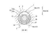
供給側油路14は、第2流動室28から第2ポート17を経て出力ポート7に作動油を導く油路であり、第2流動室28に2つの流出口14a、14bを形成して接続する。また、流出口14a、14bから流出した作動油は、再度、スリーブ12内に戻ることなく出力ポート7に導かれており、流出口14a、14bは第2ポート17を兼ねている。
また、供給側油路14は、例えば、スリーブ12の外周面において出力ポート7の全開口範囲と重なる位置に円弧状の溝37を設け、溝37と第2流動室28とを連通するように流出口14a、14bを開けることにより設けられている(図4参照。)。
The supply-
In addition, the supply-
そして、一方の流出口14aは、出力ポート7と略同一の方位、かつ、出力ポート7と軸方向に関して略同一の位置に配置されている。また、他方の流出口14bは、出力ポート7の方位と180°をなす方位、かつ、出力ポート7と軸方向に関して略同一の位置に配置されている。つまり、流出口14aは下方に向かって開口するとともに、流出口14bは上方に向かって開口し、流出口14a、14bは軸方向に関して略同一の位置に配置されている。
The one
これにより、供給側油路14によれば、流出口14aから流出した作動油は直線的に下方に流れて出力ポート7に流入し、流出口14bから流出した作動油は、溝37内を環状に下方に流れて出力ポート7に流入する。
なお、流出口14bの溝37に対する開口面積は、出力ポート7の開口面積と略同一であり、流出口14aの溝37に対する開口面積は、流出口14bの溝37に対する開口面積の1/3〜2/3の範囲である。
As a result, according to the supply
The opening area of the
抜出側油路15は、第3流動室29から第3ポート18を経て抜出ポート9に作動油を導く油路であり、第3流動室29に2つの流出口15a、15bを形成して接続する。また、流出口15a、15bから流出した作動油は、再度、スリーブ12内に戻ることなく抜出ポート9に導かれており、流出口15a、15bは第3ポート18を兼ねている。
また、抜出側油路15は、例えば、スリーブ12の外周面において抜出ポート9の全開口範囲と重なる位置に円弧状の溝38を設け、溝38と第3流動室29とを連通するように流出口15a、15bを開けることにより設けられている(図5参照。)。
The extraction-
Further, the extraction-
そして、一方の流出口15aは、抜出ポート9と略同一の方位、かつ、抜出ポート9と軸方向に関して略同一の位置に配置されている。また、他方の流出口15bは、抜出ポート9の方位と180°をなす方位、かつ、抜出ポート9と軸方向に関して略同一の位置に配置されている。つまり、流出口15aは上方に向かって開口するとともに、流出口15bは下方に向かって開口し、流出口15a、15bは軸方向に関して略同一の位置に配置されている。
One
これにより、抜出側油路15によれば、流出口15aから流出した作動油は直線的に上方に流れて抜出ポート9に流入し、流出口15bから流出した作動油は、溝38内を環状に上方に流れて抜出ポート9に流入する。
なお、流出口15bの溝38に対する開口面積は、抜出ポート9の開口面積と略同一であり、流出口15aの溝38に対する開口面積は、流出口15bの溝38に対する開口面積の1/3〜2/3の範囲である。
Thereby, according to the extraction
The opening area of the
〔実施例1の動作特性〕
実施例1の油圧制御弁1の動作特性を、比較対象の油圧制御弁1Aの動作特性との比較により説明する(図6、図7参照。)。
まず、実施例1の比較対象の油圧制御弁1Aとして、図6および図7に示すように、供給側油路14が第2流動室28に1つの流出口14aのみを形成して接続し、さらに、抜出側油路15が第3流動室29に1つの流出口15aのみを形成して接続するものを考える。
[Operational Characteristics of Example 1]
The operation characteristics of the hydraulic control valve 1 according to the first embodiment will be described by comparison with the operation characteristics of the hydraulic control valve 1A to be compared (see FIGS. 6 and 7).
First, as the hydraulic control valve 1A for comparison in Example 1, as shown in FIGS. 6 and 7, the supply
つまり、油圧制御弁1Aでは、流出口14b、15bが存在せず、流出口14a、15aは、それぞれ出力ポート7、抜出ポート9と略同一の方位に配置されている。また、流出口14a、15aの開口面積は、それぞれ出力ポート7、抜出ポート9の開口面積と略同一である。そして、流出口14a、15aは、それぞれ第2、第3ポート17、18を兼ねている。
また、油圧制御弁1、1A間で比較すべき動作特性とは、例えば、アクチュエータ25が発生する推力と供給側、抜出側の流量との相関である(図8参照。)。
That is, in the hydraulic control valve 1A, the
The operation characteristics to be compared between the hydraulic control valves 1 and 1A are, for example, the correlation between the thrust generated by the
そして、油圧制御弁1Aのように、供給側、抜出側油路14、15がそれぞれ1つの流出口14a、15aのみを形成する場合、動作特性は、供給側、抜出側の流量のいずれにおいても最大値Qmaxから減らすときに、流量が推力の変化に対して段状に急減するスティック性を示す(図8(b)参照。)。
And, like the hydraulic control valve 1A, when the supply side and extraction
例えば、推力がゼロであって供給側の流量が最大値Qmaxである状態を初期状態として、供給側の流量を最大値Qmaxから減らすために推力を増加していく場合を考える。この場合、スプール13が初期状態の位置から軸方向に移動を開始するまで、スプール13では、軸方向に関して数式1のような力の関係となる。
〔数式1〕推力≦スプリング力+静止摩擦力
For example, a case where the thrust is zero and the flow rate on the supply side is the maximum value Qmax is assumed as an initial state, and the thrust is increased in order to reduce the flow rate on the supply side from the maximum value Qmax. In this case, until the
[Formula 1] Thrust ≤ Spring force + Static friction force
ここで、静止摩擦力は、流体横力に静止摩擦係数を乗じたものであり、第2流動室28に流入した作動油が1つの流出口14aのみから供給側油路14に流出する場合、流体横力は、第2流動室28において下向きに集中してスプール13に作用する(図6参照。)。このため、静止摩擦力が大きくなってしまい、推力を相当に増加しないとスプール13は初期状態の位置から軸方向に移動することができない。そして、推力がスプリング力と静止摩擦力との和よりも僅かに大きくなると、スプール13が急激に軸方向一方側に移動して流量が急減する。このため、推力と供給側の流量との相関において、スティック性が顕在する。
Here, the static frictional force is obtained by multiplying the fluid lateral force by the static friction coefficient, and when the hydraulic oil that has flowed into the
逆に、推力が充分に大きく抜出側の流量が最大値Qmaxである状態を初期状態として、抜出側の流量を最大値Qmaxから減らすために推力を低減してスプリング力によりスプール13を駆動する場合を考える。推力が大きくスプール13が初期状態の位置から軸方向に移動することができないとき、スプール13では、軸方向に関して数式2のような力の関係となる。
〔数式2〕スプリング力≦推力+静止摩擦力
On the contrary, assuming that the thrust is sufficiently large and the flow rate on the extraction side is the maximum value Qmax, the
[Formula 2] Spring force ≤ Thrust + Static friction force
ここで、第3流動室29に流入した作動油が1つの流出口15aのみから抜出側油路15に流出する場合、流体横力は、第3流動室29において上向きに集中してスプール13に作用する(図7参照。)。このため、静止摩擦力が大きくなってしまい、推力を相当に低減しないとスプール13は初期状態の位置から軸方向に移動することができない。そして、推力と静止摩擦力との和がスプリング力よりも僅かに小さくなると、スプール13が急激に軸方向他方側に移動して流量が急減する。このため、推力と抜出側の流量との相関においてもスティック性が顕在する。
Here, when the hydraulic oil that has flowed into the
さらに、供給側、抜出側の連通状態のいずれが開であるときでも、推力を強化してスプール13を軸方向一方側に移動させているとき、スプール13では、軸方向に関して数式3のような力の関係となる。
〔数式3〕推力=スプリング力+動摩擦力
また、推力を低減してスプリング力によりスプール13を軸方向他方側に移動させているとき、スプール13では、軸方向に関して数式4のような力の関係となる。
〔数式4〕スプリング力=推力+動摩擦力
Further, when the
[Equation 3] Thrust = Spring force + Dynamic friction force Further, when the
[Formula 4] Spring force = thrust + dynamic friction force
このため、スプール13を軸方向一方側に移動させるときには、数式3に従って推力をスプリング力+動摩擦力に略一致させる必要がある。また、スプール13を軸方向他方側に移動させるときには、数式4に従って推力をスプリング力−動摩擦力に略一致させる必要がある。
For this reason, when the
この結果、同じ流量範囲で流量を変化させる場合でも、流量を増やすときと流量を減らすときとで必要とする推力が相異し、推力と供給側の流量との相関および推力と抜出側の流量との相関の両方において、ヒステリシスが現れる。そして、動摩擦力は、流体横力に動摩擦係数を乗じたものであるから、流体横力が大きいほど、スプール13を軸方向一方側に移動させるときと他方側に移動させるときとの推力の相異が大きくなってヒステリシスが大きくなる。
As a result, even when changing the flow rate in the same flow range, the required thrust differs when increasing the flow rate and when reducing the flow rate, and the correlation between the thrust and the flow rate on the supply side and the thrust and the extraction side Hysteresis appears in both correlation with flow rate. Since the dynamic friction force is obtained by multiplying the fluid lateral force by the dynamic friction coefficient, the larger the fluid lateral force, the more the thrust phase between when the
これに対し、油圧制御弁1によれば、第2流動室28に流入した作動油は、2つの流出口14a、14bから上下2方向に分配されて供給側油路14に流出する。また、流出口14a、14bの開口面積および開口する方位、ならびに供給側油路14の流路抵抗等は、供給側の連通状態が開であるときにスプール13に作用する流体横力が径方向に関し打ち消し合って実質的にゼロとなるように設定されている。
On the other hand, according to the hydraulic control valve 1, the hydraulic oil that has flowed into the
同様に、第3流動室29に流入した作動油は、2つの流出口15a、15bから上下2方向に分配されて抜出側油路15に流出する。また、流出口15a、15bの開口面積および開口する方位、ならびに抜出側油路15の流路抵抗等は、抜出側の連通状態が開であるときにスプール13に作用する流体横力が径方向に関し打ち消し合って実質的にゼロとなるように設定されている。
Similarly, the hydraulic oil that has flowed into the third
このため、静止摩擦力は小さく、供給側の流量または抜出側の流量を最大値Qmaxから低減するときにスティック性が顕在しない。また、動摩擦力も極めて小さく、推力と供給側の流量との相関および推力と抜出側の流量との相関の両方において、ヒステリシスが大幅に小さくなる(図8(a)参照。)。 For this reason, the static frictional force is small, and stickiness does not appear when the flow rate on the supply side or the flow rate on the extraction side is reduced from the maximum value Qmax. Further, the dynamic friction force is extremely small, and hysteresis is greatly reduced both in the correlation between the thrust and the flow rate on the supply side and in the correlation between the thrust and the flow rate on the extraction side (see FIG. 8A).
〔実施例1の効果〕
実施例1の油圧制御弁1によれば、供給側油路14は、第2流動室28に2つの流出口14a、14bを形成して接続し、第2流動室28に流入した作動油は、流出口14a、14bから上下2方向に分配されて供給側油路14に流出する。また、流出口14a、14bの開口面積および開口する方位、ならびに供給側油路14の流路抵抗等は、供給側の連通状態が開であるときにスプール13に作用する流体横力が径方向に関し打ち消し合って実質的にゼロとなるように設定されている。
[Effect of Example 1]
According to the hydraulic control valve 1 of the first embodiment, the supply-
同様に、抜出側油路15は、第2流動室28に2つの流出口15a、15bを形成して接続し、第3流動室29に流入した作動油は、流出口15a、15bから上下2方向に分配されて抜出側油路15に流出する。また、流出口15a、15bの開口面積および開口する方位、ならびに抜出側油路15の流路抵抗等は、抜出側の連通状態が開であるときにスプール13に作用する流体横力が径方向に関し打ち消し合って実質的にゼロとなるように設定されている。
Similarly, the extraction-
これにより、静止摩擦力を小さくすることができるので、供給側の流量または抜出側の流量を最大値Qmaxから低減するときのスティック性を解消することができる。また、動摩擦力も極めて小さくすることができるので、推力と供給側の流量との相関および推力と抜出側の流量との相関の両方において、ヒステリシスを大幅に小さくすることができる。 As a result, the static frictional force can be reduced, and stickiness when reducing the flow rate on the supply side or the flow rate on the extraction side from the maximum value Qmax can be eliminated. Also, since the dynamic friction force can be made extremely small, hysteresis can be greatly reduced both in the correlation between the thrust and the flow rate on the supply side and in the correlation between the thrust and the flow rate on the extraction side.
また、流出口14a、14bは第2ポート17を兼ね、流出口15a、15bは第3ポート18を兼ねる。
これにより、流体横力緩和のために設ける流出口14a、14bを第2ポート17と別に設けなくてもよく、さらに、流出口15a、15bを第3ポート18と別に設けなくてもよいので、構成上の煩雑さや製造上の煩雑さを低減することができる。
The
Accordingly, the
さらに、供給側の連通状態が開であるとき、作動油は、縁33bbから縁33baに向かって流れる。
これにより、供給側の連通状態が開のときに、第1ポート16から第2ポート17に向かう油路が最短になる。このため、作動油の圧力損失を低減することができる。
Furthermore, when the communication state on the supply side is open, the hydraulic oil flows from the edge 33bb toward the edge 33ba.
As a result, when the communication state on the supply side is open, the oil path from the
〔実施例2〕
実施例2の油圧制御弁1によれば、図9等に示すように、実施例1における第2流動室28は、第1流動室27の軸方向一方側と他方側とに2室に分割されている(以下、第1流動室27の軸方向一方側、他方側の第2流動室28をそれぞれ第2流動室28A、28Bと呼ぶ。)。そして、第2流動室28A、28Bは、スリーブ12の上面に設けられた軸方向に伸びる溝40により、常時、連通している。すなわち、第2流動室28A、28Bには、それぞれ中間ポート41A、41Bが上方に向けて溝40に開口しており、第2流動室28A、28Bは、溝40および中間ポート41A、41Bを介して互いに常時連通している。また、第2ポート17は、第2流動室28Aに開口している。
[Example 2]
According to the hydraulic control valve 1 of the second embodiment, as shown in FIG. 9 and the like, the
また、スプール13は、軸方向他方側に向かって順に並ぶ4つのランド23c、23d、23e、23fを有し、ランド23c、23d間、ランド23d、23e間、ランド23e、23f間にそれぞれ軸部24c、24d、24eが設けられ、ランド23fの軸方向他端から軸部24fが軸方向他方側に突出している。
The
そして、第1流動室27は、主にスリーブ12の内周壁と軸部24dの外周面との間に形成され、軸方向一方側をランド23dの他端面により画されるとともに軸方向他方側をランド23eの一端面により画され、スプール13の移動に応じて軸方向に移動する。また、第2流動室28Aは、主にスリーブ12の内周壁と軸部24cの外周面との間に形成され、軸方向一方側をランド23cの他端面により画されるとともに軸方向他方側をランド23dの一端面により画され、スプール13の移動に応じて軸方向に移動する。
The
また、第2流動室28Bは、主にスリーブ12の内周壁と軸部24eの外周面との間に形成され、軸方向一方側をランド23eの他端面により画されるとともに軸方向他方側をランド23fの一端面により画され、スプール13の移動に応じて軸方向に移動する。さらに、第3流動室29は、主にスリーブ12の内周壁とランド23cの外周面との間に形成されている。
The
そして、アクチュエータ25の推力が弱くスプール13ならびに第1流動室27および第2流動室28A、28Bが軸方向他方側に片寄るときに(図10参照。)、第1流動室27と第2流動室28Bとが連通する。また、アクチュエータ25の推力が強くスプール13ならびに第1流動室27および第2流動室28A、28Bが軸方向一方側に片寄るときに(図11参照。)、第2流動室28Aと第3流動室29とが連通する。
When the thrust of the
そして、スプール13は、スリーブ12内で軸方向に移動することで、第1、第2流動室27、28A、28Bを介する供給側の連通状態をランド23eにより調節する。同様に、スプール13は、スリーブ12内で軸方向に移動することで、第2、第3流動室28A、29を介する抜出側の連通状態をランド23cにより調節する。
Then, the
また、スリーブ12の内壁面において第3ポート18の軸方向他端には、実施例1の油圧制御弁1と同様の段部31aが設けられ、段部31aはランド23cとの間に抜出側絞り35aを形成する(図11参照。)。また、段部31aの軸方向他方側の内壁面には、実施例1と同様のシート範囲32aが形成されている(なお、実施例2ではランド23aに代わり、ランド23cがシート範囲32aに離接する。)。
Further, on the inner wall surface of the
また、スリーブ12の内壁面において中間ポート41Bの軸方向一端には、実施例1の油圧制御弁1と同様の段部31bが設けられ、段部31bはランド23eとの間に供給側絞り35bを形成する(図10参照。)。また、段部31bの軸方向一方側の内壁面には、実施例1と同様のシート範囲32bが形成されている(なお、実施例2ではランド23bに代わり、ランド23eがシート範囲32bに離接する。)。そして、ランド23eは、縁33bbから軸方向他方側に離間することで供給側の連通状態を閉から開にし、供給側の連通状態が開であるとき、作動油は、縁33baから縁33bbに向かって流れる。
Further, a
また、実施例2の供給側油路14は、第2流動室28Bから中間ポート41B、溝40、中間ポート41A、第2流動室28Aおよび第2ポート17を経て出力ポート7に作動油を導く油路である。ここで、中間ポート41Bは、溝40に向けて上方に開口するものとは別に下側にも設けられており、上下それぞれに1つずつ存在する。また、スリーブ12の外周面には、上下両方の中間ポート41Bの全開口範囲と重なるように、かつ、溝40と交差するように円弧状の溝42が設けられている(図12参照。)。
Further, the supply
これにより、上下の中間ポート41Bは、それぞれ、第2流動室28Bからの作動油の流出口14a、14bをなす。つまり、供給側油路14は、第2流動室28Bに2つの流出口14a、14bを形成して接続する。
また、作動油は、流出口14a、14b(上下の中間ポート41B)から、一旦、スリーブ12の外に流出した後、再度、中間ポート41Aからスリーブ12内である第2流動室28Aに戻り、第2ポート17から出力ポート7に流出している。つまり、流出口14a、14bは、実施例1の流出口14a、14bとは異なり第2ポート17を兼ねていない。
Thus, the upper and lower
The hydraulic oil once flows out of the
そして、流出口14b(下側の中間ポート41B)は供給ポート6や出力ポート7と略同一の方位に配置され、流出口14a(上側の中間ポート41B)は、流出口14bの方位と180°をなす方位に配置されている。これにより、実施例2の供給側油路14によれば、流出口14aから上方に流出した作動油は溝40に流入する。また、流出口14bから下方に流出した作動油は、溝42内を環状に上方に流れて溝40に流入し、流出口14aから流出した作動油と合流して第2流動室28Aに流入する。
The
なお、流出口14bの溝42に対する開口面積は、出力ポート7の開口面積と略同一であり、流出口14aの溝42に対する開口面積は、流出口14bの溝42に対する開口面積の1/3〜2/3の範囲である。
また、実施例2の抜出側油路15は、実施例1の抜出側油路15と同様に構成されている(図13参照。)。
The opening area of the
Further, the extraction-
以上により、実施例2の油圧制御弁1を使用した場合にも、スプール13に作用する流体横力が径方向に関し実質的にゼロとなるように、流出口14a、14bの開口面積および開口する方位、ならびに供給側油路14の流路抵抗等を設定することができる。このため、実施例1と同様に、油圧制御弁1の動作特性におけるスティック性を解消することができるとともに、ヒステリシスを大幅に小さくすることができる。
As described above, even when the hydraulic control valve 1 of the second embodiment is used, the opening areas and openings of the
さらに、供給側の連通状態が開であるとき、作動油は、縁33baから縁33bbに向かって流れる。
これにより、供給側の連通状態が開のときに、供給側絞り35bから噴出する作動油は、スプール13に対し供給側の連通状態に関して開側に動圧を与える。このため、スプール13を供給側の連通状態に関して開側に駆動するための力(スプリング力)を低減することができる。
Furthermore, when the communication state on the supply side is open, the hydraulic oil flows from the edge 33ba toward the edge 33bb.
Accordingly, when the supply side communication state is open, the hydraulic oil ejected from the
〔変形例〕
油圧制御弁1の態様は、実施例に限定されず種々の変形例を考えることができる。
例えば、実施例1、2の油圧制御弁1は、制御対象2への作動油の供給、および制御対象2からの作動油の抜出の両方を行うことができるものであったが、制御対象2への作動油の供給、または制御対象2からの作動油の抜出のいずれか一方のみを行うことができるように油圧制御弁1を設けてもよい。
[Modification]
The aspect of the hydraulic control valve 1 is not limited to the embodiment, and various modifications can be considered.
For example, the hydraulic control valve 1 according to the first and second embodiments is capable of both supplying the hydraulic oil to the controlled
また、実施例1、2の油圧制御弁1によれば、供給側油路14に関して2つの流出口14a、14bが形成され、抜出側油路15に関して2つの流出口15a、15bが形成されていたが、供給側油路14に関して3つ以上の流出口を形成してもよく、抜出側油路15に関して3つ以上の流出口を形成してもよい。
Further, according to the hydraulic control valve 1 of the first and second embodiments, the two
さらに、供給側、抜出側油路14、15の態様は実施例1、2に限定されず、様々な態様で設定することができる。例えば、実施例1と同様の第1、第2流動室27、28を形成するとともに、供給側油路14に関し2つの流出口14a、14bを形成する場合、流出口14a、14bを互いに軸方向にずらして第2流動室27に開口させてもよい。
Furthermore, the modes of the supply side and extraction
1 油圧制御弁 2 制御対象 4 空洞 5 供給源 6 供給ポート 7 出力ポート 8 抜出先 9 抜出ポート 12 スリーブ 13 スプール 14 供給側油路 14a、14b、15a、15b 流出口 15 抜出側油路 16 第1ポート 17 第2ポート 18 第3ポート 23a、23b、23c、23e ランド 28、28b 第2流動室(流動室) 29 第3流動室(流動室)
DESCRIPTION OF SYMBOLS 1
Claims (8)
作動油の供給源(5)に接続する供給ポート(6)および前記制御対象(2)の油圧室と接続する出力ポート(7)が開口する筒状の空洞(4)に装着され、前記供給ポート(6)と前記出力ポート(7)との連通状態を調節することにより、前記制御対象(2)における油圧を制御する油圧制御弁(1)において、
前記空洞(4)への装着により、前記供給ポート(6)および前記出力ポート(7)のそれぞれと連通する第1、第2ポート(16、17)を有する筒状のスリーブ(12)と、
このスリーブ(12)の内周壁に軸方向に摺動自在に支持されるランド(23b、23e)を有し、前記スリーブ(12)の内周壁との間に作動油の流動室(28、28B)を形成し、前記スリーブ(12)内で軸方向に変位することで、前記ランド(23b、23e)により、前記流動室(28、28B)を介する前記第1ポート(16)と前記第2ポート(17)との連通状態を調節するスプール(13)と、
前記流動室(28、28B)から前記第2ポート(17)を経て前記出力ポート(7)に作動油を導く油路であり、前記流動室(28、28B)に複数の流出口(14a、14b)を形成して接続する供給側油路(14)とを備えており、
前記供給側油路(14)は、前記複数の流出口(14a、14b)として、
前記出力ポート(7)と略同一の方位に配置された一方の流出口(14a)と、前記一方の流出口(14a)と径方向反対側に配置された他方の流出口(14b)とを少なくとも備え、
前記他方の流出口(14b)の開口面積を、前記一方の流出口(14a)の開口面積より大きくしていることを特徴とする油圧制御弁(1)。 A valve device for supplying hydraulic oil to a hydraulic control target (2);
The supply port (6) connected to the hydraulic oil supply source (5) and the output port (7) connected to the hydraulic chamber of the controlled object (2) are mounted in an open cylindrical cavity (4), and the supply In the hydraulic control valve (1) for controlling the hydraulic pressure in the controlled object (2) by adjusting the communication state between the port (6) and the output port (7),
A cylindrical sleeve (12) having first and second ports (16, 17) communicating with each of the supply port (6) and the output port (7) by being mounted in the cavity (4);
Lands (23b, 23e) are slidably supported in the axial direction on the inner peripheral wall of the sleeve (12), and hydraulic fluid flow chambers (28, 28B) between the inner peripheral wall of the sleeve (12). ) And is displaced axially in the sleeve (12), so that the land (23b, 23e) causes the first port (16) and the second port to pass through the flow chamber (28, 28B). A spool (13) for adjusting the communication state with the port (17);
An oil passage that guides hydraulic oil from the flow chamber (28, 28B) to the output port (7) through the second port (17), and a plurality of outlets (14a, A supply-side oil passage (14) that forms and connects 14b) ,
The supply side oil passage (14) serves as the plurality of outlets (14a, 14b).
One outlet (14a) arranged in substantially the same orientation as the output port (7), and the other outlet (14b) arranged radially opposite to the one outlet (14a). At least ,
The hydraulic control valve (1) , wherein an opening area of the other outlet (14b) is larger than an opening area of the one outlet (14a ).
前記制御対象(2)の油圧室と接続する出力ポート(7)および作動油の抜出先(8)に接続する抜出ポート(9)が開口する筒状の空洞(4)に装着され、前記出力ポート(7)と前記抜出ポート(9)との連通状態を調節することにより、前記制御対象(2)における油圧を制御する油圧制御弁(1)において、
前記空洞(4)への装着により、前記出力ポート(7)および前記抜出ポート(9)のそれぞれと連通する第2、第3ポート(17、18)を有する筒状のスリーブ(12)と、
このスリーブ(12)の内周壁に軸方向に摺動自在に支持されるランド(23a、23c)を有し、前記スリーブ(12)の内周壁との間に作動油の流動室(29)を形成し、前記スリーブ(12)内で軸方向に変位することで、前記ランド(23a、23c)により、前記流動室(29)を介する前記第2ポート(17)と前記第3ポート(18)との連通状態を調節するスプール(13)と、
前記流動室(29)から前記第3ポート(18)を経て前記抜出ポート(9)に作動油を導く油路であり、前記流動室(29)に複数の流出口(15a、15b)を形成して接続する抜出側油路(15)とを備えており、
前記抜出側油路(15)は、前記複数の流出口(15a、15b)として、
前記出力ポート(9)と略同一の方位に配置された一方の流出口(15a)と、前記一方の流出口(15a)と径方向反対側に配置された他方の流出口(15b)とを少なくとも備え、
前記他方の流出口(15b)の開口面積を、前記一方の流出口(15a)の開口面積より大きくしていることを特徴とする油圧制御弁(1)。 It is a valve device that extracts hydraulic oil from the hydraulic control target (2),
The output port (7) connected to the hydraulic chamber of the controlled object (2) and the extraction port (9) connected to the hydraulic oil extraction destination (8) are mounted in an open cylindrical cavity (4), and In the hydraulic control valve (1) for controlling the hydraulic pressure in the controlled object (2) by adjusting the communication state between the output port (7) and the extraction port (9),
A cylindrical sleeve (12) having second and third ports (17, 18) communicating with each of the output port (7) and the extraction port (9) by being mounted in the cavity (4); ,
The sleeve (12) has lands (23a, 23c) slidably supported in the axial direction on the inner peripheral wall thereof, and a hydraulic fluid flow chamber (29) is provided between the inner peripheral wall of the sleeve (12). The second port (17) and the third port (18) through the flow chamber (29) are formed by the lands (23a, 23c) by being formed and displaced in the axial direction in the sleeve (12). A spool (13) for adjusting the communication state with
An oil passage that leads hydraulic fluid from the fluid chamber (29) to the extraction port (9) through the third port (18), and a plurality of outlets (15a, 15b) are provided in the fluid chamber (29). An extraction side oil passage (15) to be formed and connected ,
The extraction side oil passage (15) serves as the plurality of outlets (15a, 15b),
One outflow port (15a) disposed in substantially the same direction as the output port (9), and the other outflow port (15b) disposed radially opposite to the one outflow port (15a). At least,
The hydraulic control valve (1) , wherein an opening area of the other outlet (15b) is larger than an opening area of the one outlet (15a ).
前記複数の流出口(14a、14b)は、前記第2ポート(17)を兼ねることを特徴とする油圧制御弁(1)。 In the hydraulic control valve (1) according to claim 1,
The hydraulic control valve (1), wherein the plurality of outlets (14a, 14b) also serve as the second port (17).
前記複数の流出口(15a、15b)は、前記第3ポート(18)を兼ねることを特徴とする油圧制御弁(1)。 In the hydraulic control valve (1) according to claim 2,
The hydraulic control valve (1), wherein the plurality of outlets (15a, 15b) also serve as the third port (18).
前記流動室(28)には2つの流出口(14a、14b)が接続しており、一方の流出口(14a)は前記出力ポート(7)と略同一の方位に配置され、他方の流出口(14b)は、前記出力ポート(7)の方位と180°をなす方位に配置され、
前記他方の流出口(14b)の開口面積は、前記出力ポート(7)の開口面積と略同一であり、
前記一方の流出口(14a)の開口面積は、前記他方の流出口(14b)の開口面積の1/3〜2/3の範囲であることを特徴とする油圧制御弁(1)。 In the hydraulic control valve (1) according to claim 3,
Two outlets (14a, 14b) are connected to the flow chamber (28), and one outlet (14a) is disposed in substantially the same direction as the output port (7), and the other outlet is provided. (14b) is arranged in an azimuth of 180 ° with the azimuth of the output port (7),
The opening area of the other outlet (14b) is substantially the same as the opening area of the output port (7),
The hydraulic control valve (1), wherein an opening area of the one outlet (14a) is in a range of 1/3 to 2/3 of an opening area of the other outlet (14b).
前記流動室(29)には2つの流出口(15a、15b)が接続しており、一方の流出口(15a)は前記抜出ポート(9)と略同一の方位に配置され、他方の流出口(15b)は、前記抜出ポート(9)の方位と180°をなす方位に配置され、
前記他方の流出口(15b)の開口面積は、前記抜出ポート(9)の開口面積と略同一であり、
前記一方の流出口(15a)の開口面積は、前記他方の流出口(15b)の開口面積の1/3〜2/3の範囲であることを特徴とする油圧制御弁(1)。 In the hydraulic control valve (1) according to claim 4,
Two outlets (15a, 15b) are connected to the flow chamber (29), and one outlet (15a) is arranged in substantially the same direction as the extraction port (9), and the other outlet (15a) is connected to the outlet (15a). The outlet (15b) is arranged at an orientation of 180 ° with the orientation of the extraction port (9),
The opening area of the other outlet (15b) is substantially the same as the opening area of the extraction port (9),
The hydraulic control valve (1), wherein an opening area of the one outlet (15a) is in a range of 1/3 to 2/3 of an opening area of the other outlet (15b).
前記スリーブ(12)の内壁面には、前記第1ポート(16)と前記第2ポート(17)との連通状態である供給側の連通状態が閉であるときに前記ランド(23b)の摺接を受けるとともに開であるときに摺接を受けないシート範囲(32b)が存在し、このシート範囲(32b)は、軸方向における一方側の縁(33ba)と他方側の縁(33bb)とにより区画され、
前記供給側の連通状態が開であるとき、前記第1ポート(16)から前記第2ポート(17)に向かう作動油は、前記他方側の縁(33bb)から前記一方側の縁(33ba)に向かって流れ、
前記ランド(23b)は、前記他方側の縁(33bb)から軸方向他方側に離間することで、前記供給側の連通状態を閉から開にすることを特徴とする油圧制御弁(1)。 In the hydraulic control valve (1) according to any one of claims 1, 3 and 5,
The inner wall surface of the sleeve (12) is slid on the land (23b) when the supply side communication state between the first port (16) and the second port (17) is closed. There is a sheet range (32b) that receives contact and does not receive sliding contact when open, and this sheet range (32b) includes an edge (33ba) on one side and an edge (33bb) on the other side in the axial direction. Divided by
When the communication state on the supply side is open, hydraulic fluid from the first port (16) to the second port (17) flows from the other edge (33bb) to the one edge (33ba). Flow towards
The hydraulic control valve (1), wherein the land (23b) is spaced apart from the other side edge (33bb) to the other side in the axial direction to change the communication state on the supply side from closed to open.
前記スリーブ(12)の内壁面には、前記第1ポート(16)と前記第2ポート(17)との連通状態である供給側の連通状態が閉であるときに前記ランド(23e)の摺接を受けるとともに開であるときに摺接を受けないシート範囲(32b)が存在し、このシート範囲(32b)は、軸方向における一方側の縁(33ba)と他方側の縁(33bb)とにより区画され、
前記供給側の連通状態が開であるとき、前記第1ポート(16)から前記第2ポート(17)に向かう作動油は、前記一方側の縁(33ba)から前記他方側の縁(33bb)に向かって流れ、
前記ランド(23e)は、前記他方側の縁(33bb)から軸方向他方側に離間することで、前記供給側の連通状態を閉から開にすることを特徴とする油圧制御弁(1)。 In the hydraulic control valve (1) according to any one of claims 1, 3 and 5,
The inner wall surface of the sleeve (12) is slid on the land (23e) when the supply side communication state between the first port (16) and the second port (17) is closed. There is a sheet range (32b) that receives contact and does not receive sliding contact when open, and this sheet range (32b) includes an edge (33ba) on one side and an edge (33bb) on the other side in the axial direction. Divided by
When the communication state on the supply side is open, the hydraulic oil from the first port (16) to the second port (17) flows from the one side edge (33ba) to the other side edge (33bb). Flow towards
The hydraulic control valve (1) according to claim 1, wherein the land (23e) is separated from the other side edge (33bb) to the other side in the axial direction to change the communication state on the supply side from closed to open.
Priority Applications (3)
| Application Number | Priority Date | Filing Date | Title |
|---|---|---|---|
| JP2012252879A JP5708618B2 (en) | 2012-11-19 | 2012-11-19 | Hydraulic control valve |
| US14/045,848 US9772039B2 (en) | 2012-11-19 | 2013-10-04 | Hydraulic pressure control valve |
| CN201310573158.3A CN103821786B (en) | 2012-11-19 | 2013-11-15 | Hydraulic control valve |
Applications Claiming Priority (1)
| Application Number | Priority Date | Filing Date | Title |
|---|---|---|---|
| JP2012252879A JP5708618B2 (en) | 2012-11-19 | 2012-11-19 | Hydraulic control valve |
Publications (2)
| Publication Number | Publication Date |
|---|---|
| JP2014101914A JP2014101914A (en) | 2014-06-05 |
| JP5708618B2 true JP5708618B2 (en) | 2015-04-30 |
Family
ID=50726782
Family Applications (1)
| Application Number | Title | Priority Date | Filing Date |
|---|---|---|---|
| JP2012252879A Expired - Fee Related JP5708618B2 (en) | 2012-11-19 | 2012-11-19 | Hydraulic control valve |
Country Status (3)
| Country | Link |
|---|---|
| US (1) | US9772039B2 (en) |
| JP (1) | JP5708618B2 (en) |
| CN (1) | CN103821786B (en) |
Families Citing this family (3)
| Publication number | Priority date | Publication date | Assignee | Title |
|---|---|---|---|---|
| WO2016129058A1 (en) * | 2015-02-10 | 2016-08-18 | 三菱電機株式会社 | Control valve |
| DE102017012102A1 (en) * | 2017-12-21 | 2019-06-27 | Hydac Fluidtechnik Gmbh | Device and valve for flow force compensation |
| WO2021128156A1 (en) * | 2019-12-26 | 2021-07-01 | 博世力士乐(常州)有限公司 | Spool valve |
Family Cites Families (10)
| Publication number | Priority date | Publication date | Assignee | Title |
|---|---|---|---|---|
| JP2514340Y2 (en) * | 1989-07-20 | 1996-10-16 | カヤバ工業株式会社 | Spool type control valve |
| JPH10289018A (en) | 1997-04-10 | 1998-10-27 | Toyota Motor Corp | Pressure regulating valve |
| JP3839562B2 (en) * | 1997-09-17 | 2006-11-01 | カヤバ工業株式会社 | Spool valve |
| TW541405B (en) * | 2001-08-15 | 2003-07-11 | Amada Co Ltd | Directional control valve |
| JP4072363B2 (en) * | 2002-03-25 | 2008-04-09 | 株式会社ジェイテクト | Valve assembly |
| JP4100161B2 (en) * | 2002-09-30 | 2008-06-11 | 株式会社ジェイテクト | solenoid valve |
| JP2007139074A (en) * | 2005-11-18 | 2007-06-07 | Sumitomo Metal Mining Co Ltd | Air pulse generator |
| US8127790B2 (en) * | 2009-03-25 | 2012-03-06 | Husco Automotive Holdings Llc | Hydraulic valve with a filter and check valve band |
| CN102459965B (en) * | 2009-06-29 | 2014-11-05 | 博格华纳公司 | Hydraulic valve for use in a control module of an automatic transmission |
| FR2960924B1 (en) * | 2010-06-04 | 2013-04-05 | Messier Bugatti | HYDRAULIC DISTRIBUTOR. |
-
2012
- 2012-11-19 JP JP2012252879A patent/JP5708618B2/en not_active Expired - Fee Related
-
2013
- 2013-10-04 US US14/045,848 patent/US9772039B2/en not_active Expired - Fee Related
- 2013-11-15 CN CN201310573158.3A patent/CN103821786B/en not_active Expired - Fee Related
Also Published As
| Publication number | Publication date |
|---|---|
| US20140137968A1 (en) | 2014-05-22 |
| US9772039B2 (en) | 2017-09-26 |
| CN103821786B (en) | 2017-03-01 |
| JP2014101914A (en) | 2014-06-05 |
| CN103821786A (en) | 2014-05-28 |
Similar Documents
| Publication | Publication Date | Title |
|---|---|---|
| US10495177B2 (en) | Solenoid valve | |
| EP2975291B1 (en) | Damping valve | |
| EP2975292B1 (en) | Damping valve | |
| CN105308352B (en) | Valve device | |
| CN105593564B (en) | Hydraulic bjuffer | |
| JP6378618B2 (en) | Damping valve and shock absorber | |
| CN101688628B (en) | Force feedback poppet valve having an integrated pressure compensator | |
| JP6093587B2 (en) | Solenoid valve | |
| EP3351837B1 (en) | Damping valve and shock absorber | |
| JP5369400B2 (en) | Flow control valve | |
| JP6333954B2 (en) | Valve device | |
| JP5966094B2 (en) | Solenoid valve | |
| EP3553324A1 (en) | Valve and hydraulic system with the same | |
| JP5708618B2 (en) | Hydraulic control valve | |
| US8534639B1 (en) | Solenoid valve with a digressively damped armature | |
| JPWO2018180367A1 (en) | Solenoid proportional valve | |
| JP2013117293A (en) | Flow control valve | |
| JP2017020562A (en) | Relief valve | |
| JP7513891B2 (en) | Normally open solenoid valve | |
| JP2010174940A (en) | Sequence valve | |
| JP2018025253A (en) | Fluid control system | |
| WO2016152261A1 (en) | Hydraulic control circuit | |
| JP2015209867A (en) | Hydraulic drive |
Legal Events
| Date | Code | Title | Description |
|---|---|---|---|
| A621 | Written request for application examination |
Free format text: JAPANESE INTERMEDIATE CODE: A621 Effective date: 20140407 |
|
| A977 | Report on retrieval |
Free format text: JAPANESE INTERMEDIATE CODE: A971007 Effective date: 20141016 |
|
| A131 | Notification of reasons for refusal |
Free format text: JAPANESE INTERMEDIATE CODE: A131 Effective date: 20141021 |
|
| A521 | Written amendment |
Free format text: JAPANESE INTERMEDIATE CODE: A523 Effective date: 20141211 |
|
| TRDD | Decision of grant or rejection written | ||
| A01 | Written decision to grant a patent or to grant a registration (utility model) |
Free format text: JAPANESE INTERMEDIATE CODE: A01 Effective date: 20150203 |
|
| A61 | First payment of annual fees (during grant procedure) |
Free format text: JAPANESE INTERMEDIATE CODE: A61 Effective date: 20150216 |
|
| R151 | Written notification of patent or utility model registration |
Ref document number: 5708618 Country of ref document: JP Free format text: JAPANESE INTERMEDIATE CODE: R151 |
|
| R250 | Receipt of annual fees |
Free format text: JAPANESE INTERMEDIATE CODE: R250 |
|
| R250 | Receipt of annual fees |
Free format text: JAPANESE INTERMEDIATE CODE: R250 |
|
| R250 | Receipt of annual fees |
Free format text: JAPANESE INTERMEDIATE CODE: R250 |
|
| LAPS | Cancellation because of no payment of annual fees |