JP5525258B2 - Method for manufacturing ceramic honeycomb structure and ceramic honeycomb structure - Google Patents
Method for manufacturing ceramic honeycomb structure and ceramic honeycomb structure Download PDFInfo
- Publication number
- JP5525258B2 JP5525258B2 JP2009515231A JP2009515231A JP5525258B2 JP 5525258 B2 JP5525258 B2 JP 5525258B2 JP 2009515231 A JP2009515231 A JP 2009515231A JP 2009515231 A JP2009515231 A JP 2009515231A JP 5525258 B2 JP5525258 B2 JP 5525258B2
- Authority
- JP
- Japan
- Prior art keywords
- ceramic honeycomb
- outer peripheral
- honeycomb structure
- peripheral wall
- coating material
- Prior art date
- Legal status (The legal status is an assumption and is not a legal conclusion. Google has not performed a legal analysis and makes no representation as to the accuracy of the status listed.)
- Active
Links
Images


Classifications
-
- F—MECHANICAL ENGINEERING; LIGHTING; HEATING; WEAPONS; BLASTING
- F01—MACHINES OR ENGINES IN GENERAL; ENGINE PLANTS IN GENERAL; STEAM ENGINES
- F01N—GAS-FLOW SILENCERS OR EXHAUST APPARATUS FOR MACHINES OR ENGINES IN GENERAL; GAS-FLOW SILENCERS OR EXHAUST APPARATUS FOR INTERNAL-COMBUSTION ENGINES
- F01N3/00—Exhaust or silencing apparatus having means for purifying, rendering innocuous, or otherwise treating exhaust
- F01N3/02—Exhaust or silencing apparatus having means for purifying, rendering innocuous, or otherwise treating exhaust for cooling, or for removing solid constituents of, exhaust
- F01N3/021—Exhaust or silencing apparatus having means for purifying, rendering innocuous, or otherwise treating exhaust for cooling, or for removing solid constituents of, exhaust by means of filters
- F01N3/022—Exhaust or silencing apparatus having means for purifying, rendering innocuous, or otherwise treating exhaust for cooling, or for removing solid constituents of, exhaust by means of filters characterised by specially adapted filtering structure, e.g. honeycomb, mesh or fibrous
- F01N3/0222—Exhaust or silencing apparatus having means for purifying, rendering innocuous, or otherwise treating exhaust for cooling, or for removing solid constituents of, exhaust by means of filters characterised by specially adapted filtering structure, e.g. honeycomb, mesh or fibrous the structure being monolithic, e.g. honeycombs
-
- C—CHEMISTRY; METALLURGY
- C04—CEMENTS; CONCRETE; ARTIFICIAL STONE; CERAMICS; REFRACTORIES
- C04B—LIME, MAGNESIA; SLAG; CEMENTS; COMPOSITIONS THEREOF, e.g. MORTARS, CONCRETE OR LIKE BUILDING MATERIALS; ARTIFICIAL STONE; CERAMICS; REFRACTORIES; TREATMENT OF NATURAL STONE
- C04B38/00—Porous mortars, concrete, artificial stone or ceramic ware; Preparation thereof
- C04B38/0006—Honeycomb structures
-
- C—CHEMISTRY; METALLURGY
- C04—CEMENTS; CONCRETE; ARTIFICIAL STONE; CERAMICS; REFRACTORIES
- C04B—LIME, MAGNESIA; SLAG; CEMENTS; COMPOSITIONS THEREOF, e.g. MORTARS, CONCRETE OR LIKE BUILDING MATERIALS; ARTIFICIAL STONE; CERAMICS; REFRACTORIES; TREATMENT OF NATURAL STONE
- C04B41/00—After-treatment of mortars, concrete, artificial stone or ceramics; Treatment of natural stone
- C04B41/009—After-treatment of mortars, concrete, artificial stone or ceramics; Treatment of natural stone characterised by the material treated
-
- C—CHEMISTRY; METALLURGY
- C04—CEMENTS; CONCRETE; ARTIFICIAL STONE; CERAMICS; REFRACTORIES
- C04B—LIME, MAGNESIA; SLAG; CEMENTS; COMPOSITIONS THEREOF, e.g. MORTARS, CONCRETE OR LIKE BUILDING MATERIALS; ARTIFICIAL STONE; CERAMICS; REFRACTORIES; TREATMENT OF NATURAL STONE
- C04B41/00—After-treatment of mortars, concrete, artificial stone or ceramics; Treatment of natural stone
- C04B41/45—Coating or impregnating, e.g. injection in masonry, partial coating of green or fired ceramics, organic coating compositions for adhering together two concrete elements
- C04B41/50—Coating or impregnating, e.g. injection in masonry, partial coating of green or fired ceramics, organic coating compositions for adhering together two concrete elements with inorganic materials
- C04B41/5076—Coating or impregnating, e.g. injection in masonry, partial coating of green or fired ceramics, organic coating compositions for adhering together two concrete elements with inorganic materials with masses bonded by inorganic cements
- C04B41/5089—Silica sols, alkyl, ammonium or alkali metal silicate cements
-
- C—CHEMISTRY; METALLURGY
- C04—CEMENTS; CONCRETE; ARTIFICIAL STONE; CERAMICS; REFRACTORIES
- C04B—LIME, MAGNESIA; SLAG; CEMENTS; COMPOSITIONS THEREOF, e.g. MORTARS, CONCRETE OR LIKE BUILDING MATERIALS; ARTIFICIAL STONE; CERAMICS; REFRACTORIES; TREATMENT OF NATURAL STONE
- C04B41/00—After-treatment of mortars, concrete, artificial stone or ceramics; Treatment of natural stone
- C04B41/80—After-treatment of mortars, concrete, artificial stone or ceramics; Treatment of natural stone of only ceramics
- C04B41/81—Coating or impregnation
- C04B41/85—Coating or impregnation with inorganic materials
-
- C—CHEMISTRY; METALLURGY
- C04—CEMENTS; CONCRETE; ARTIFICIAL STONE; CERAMICS; REFRACTORIES
- C04B—LIME, MAGNESIA; SLAG; CEMENTS; COMPOSITIONS THEREOF, e.g. MORTARS, CONCRETE OR LIKE BUILDING MATERIALS; ARTIFICIAL STONE; CERAMICS; REFRACTORIES; TREATMENT OF NATURAL STONE
- C04B2111/00—Mortars, concrete or artificial stone or mixtures to prepare them, characterised by specific function, property or use
- C04B2111/00474—Uses not provided for elsewhere in C04B2111/00
- C04B2111/00793—Uses not provided for elsewhere in C04B2111/00 as filters or diaphragms
-
- C—CHEMISTRY; METALLURGY
- C04—CEMENTS; CONCRETE; ARTIFICIAL STONE; CERAMICS; REFRACTORIES
- C04B—LIME, MAGNESIA; SLAG; CEMENTS; COMPOSITIONS THEREOF, e.g. MORTARS, CONCRETE OR LIKE BUILDING MATERIALS; ARTIFICIAL STONE; CERAMICS; REFRACTORIES; TREATMENT OF NATURAL STONE
- C04B2111/00—Mortars, concrete or artificial stone or mixtures to prepare them, characterised by specific function, property or use
- C04B2111/00474—Uses not provided for elsewhere in C04B2111/00
- C04B2111/0081—Uses not provided for elsewhere in C04B2111/00 as catalysts or catalyst carriers
-
- F—MECHANICAL ENGINEERING; LIGHTING; HEATING; WEAPONS; BLASTING
- F01—MACHINES OR ENGINES IN GENERAL; ENGINE PLANTS IN GENERAL; STEAM ENGINES
- F01N—GAS-FLOW SILENCERS OR EXHAUST APPARATUS FOR MACHINES OR ENGINES IN GENERAL; GAS-FLOW SILENCERS OR EXHAUST APPARATUS FOR INTERNAL-COMBUSTION ENGINES
- F01N2330/00—Structure of catalyst support or particle filter
- F01N2330/06—Ceramic, e.g. monoliths
-
- Y—GENERAL TAGGING OF NEW TECHNOLOGICAL DEVELOPMENTS; GENERAL TAGGING OF CROSS-SECTIONAL TECHNOLOGIES SPANNING OVER SEVERAL SECTIONS OF THE IPC; TECHNICAL SUBJECTS COVERED BY FORMER USPC CROSS-REFERENCE ART COLLECTIONS [XRACs] AND DIGESTS
- Y02—TECHNOLOGIES OR APPLICATIONS FOR MITIGATION OR ADAPTATION AGAINST CLIMATE CHANGE
- Y02T—CLIMATE CHANGE MITIGATION TECHNOLOGIES RELATED TO TRANSPORTATION
- Y02T10/00—Road transport of goods or passengers
- Y02T10/10—Internal combustion engine [ICE] based vehicles
- Y02T10/12—Improving ICE efficiencies
-
- Y—GENERAL TAGGING OF NEW TECHNOLOGICAL DEVELOPMENTS; GENERAL TAGGING OF CROSS-SECTIONAL TECHNOLOGIES SPANNING OVER SEVERAL SECTIONS OF THE IPC; TECHNICAL SUBJECTS COVERED BY FORMER USPC CROSS-REFERENCE ART COLLECTIONS [XRACs] AND DIGESTS
- Y10—TECHNICAL SUBJECTS COVERED BY FORMER USPC
- Y10T—TECHNICAL SUBJECTS COVERED BY FORMER US CLASSIFICATION
- Y10T428/00—Stock material or miscellaneous articles
- Y10T428/24—Structurally defined web or sheet [e.g., overall dimension, etc.]
- Y10T428/24149—Honeycomb-like
Landscapes
- Chemical & Material Sciences (AREA)
- Engineering & Computer Science (AREA)
- Ceramic Engineering (AREA)
- Organic Chemistry (AREA)
- Materials Engineering (AREA)
- Structural Engineering (AREA)
- Inorganic Chemistry (AREA)
- General Engineering & Computer Science (AREA)
- Mechanical Engineering (AREA)
- Combustion & Propulsion (AREA)
- Filtering Materials (AREA)
- Catalysts (AREA)
- Filtering Of Dispersed Particles In Gases (AREA)
- Paints Or Removers (AREA)
- Laminated Bodies (AREA)
Description
本発明は、排気ガス浄化用の触媒コンバータや微粒子捕集用のフィルタに使用されるセラミックハニカム構造体及びその製造方法に関する。 The present invention relates to a ceramic honeycomb structure used for a catalytic converter for purifying exhaust gas and a filter for collecting fine particles, and a method for manufacturing the same.
地域環境や地球環境の保全面から、自動車などのエンジンの排気ガス中に含まれる有害物質を削減するため、セラミックハニカム構造体を使用した排気ガス浄化用の触媒担体や微粒子捕集用のフィルタが使用されている。 In order to reduce harmful substances contained in the exhaust gas of engines such as automobiles from the viewpoint of preservation of the local environment and the global environment, a catalyst carrier for purifying exhaust gas using a ceramic honeycomb structure and a filter for collecting particulates are used. It is used.
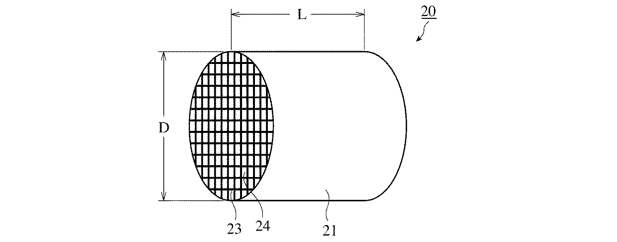
従来のセラミックハニカム構造体20は、図2に示すように、各々直交する隔壁23により形成された多数の流路24と外周壁21とからなり、その流路垂直方向断面の形状は通常ほぼ円形又は楕円形をしている。セラミックハニカム構造体20の前記外周壁21は、金属メッシュ又はセラミックス製のマット等で形成された把持部材(図示せず)で使用中に動かないように把持され、金属製収納容器(図示せず)内に配置されている。
As shown in FIG. 2, the conventional
セラミックハニカム構造体20は、(1)セラミック原料(例えばコージェライト粉末)、成形助剤、造孔材等の原料と水を混合及び混練してセラミック坏土を作製する工程、(2)セラミック坏土をハニカム形状口金から押出して、外周壁21と隔壁23とが一体に形成されたハニカム構造を有するセラミックハニカム成形体とする工程、(3)成形体を乾燥及び焼成する工程で製造される。このような工程により、所定の形状と強度を有し、隔壁23に微細な細孔を有するセラミックハニカム構造体20が得られる。
The
ディーゼルエンジンからの排気ガスを浄化するフィルタには、図2における外径Dが150 mm以上及び長さLが150 mm以上の大型で、隔壁23の厚さが0.2 mm以下と薄いセラミックハニカム構造体20を使用する場合がある。このような大型で隔壁が薄いセラミックハニカム構造体20を製造する場合、セラミック杯土を押出して得られるセラミックハニカム成形体の強度不足のため、自重によって成形体の外周壁21の周縁部の隔壁23が潰れて変形するという問題が生じる。変形した成形体を焼成しても、所定の強度を有するセラミックハニカム構造体20が得られない。
A filter for purifying exhaust gas from a diesel engine is a large ceramic honeycomb structure with an outer diameter D of 150 mm or more and a length L of 150 mm or more in FIG. 2 and a
特開平5-269388号は、この問題を解決するために、図1(a)及び図1(b)に示すように、隔壁13で囲まれた多数のセル14のうち、外周面に位置するセル14aによって形成される凹溝15にコージェライト粒子及び/又はセラミックファイバーとコロイド状酸化物(コロイダルシリカ、コロイダルアルミナ等)とを主成分とし水を加えて混練して得たペースト状のコート材12cを充填し、乾燥又は乾燥及び焼成することで、セラミックハニカム本体11に固着した外周壁12が形成されたハニカム構造体10を開示している。特開平5-269388号は、塗布したコート材12cを大気中で24時間放置し、さらに90℃で2時間乾燥を行って外周壁12を形成する方法を記載している。
In order to solve this problem, Japanese Patent Application Laid-Open No. 5-269388 is located on the outer peripheral surface of a large number of
特開平5-269388号に記載されたような外部から加熱して行う乾燥方法では、コート材12cの表層部12sがまず加熱され、徐々に内部12nへ熱が伝わる。このため、コート材12cの表層部12sが先に乾燥し、その後内部12nの水分が表面に移動して、既に乾燥開始している表層部12sから蒸発することによって内部12nの乾燥が進行する。従って、乾燥の途中段階ではコート材12cの表層部12sと内部12nとの間に含水量の差が生じ、乾燥収縮度の差からコート材表面12sにクラック16が生じやすくなるといった問題を生じる。特に、外周壁が厚くなったり、加熱温度を高くして乾燥時間を短縮させようとしたりすると、この含水量の差がより大きくなり、さらにクラック16が生じやすくなる。外周壁がこのようなクラックを有すると、クラックが破壊の起点となって、セラミックハニカム構造体の強度が低下したり、熱衝撃割れの原因となったりするため好ましくない。
In the drying method performed by heating from the outside as described in JP-A-5-269388, the
特開2006-298745号は、図1(a)及び図1(b)に示す外周をコート材12cで被覆したセラミックハニカム構造体10を開示している。粒度15〜75μmのセルベン及び26〜34質量%の水分を含有するスラリーをコート材12cとして使用し、外周壁を形成することにより、強制乾燥(遠赤外線及び/又は熱風乾燥)してもコート材12cにクラックが発生しにくく、そのため製造時間を短縮できると記載している。
Japanese Patent Laid-Open No. 2006-298745 discloses a
しかしながら、特にディーゼルエンジン等に用いる外径Dが150 mm以上及び長さLが150 mm以上の大型のセラミックハニカム構造体を製造する場合、特開2006-298745号に記載されたセルベンを含むコート材を用いても、遠赤外線及び/又は熱風を用いた強制乾燥では外周壁12を一様に乾燥させるのは難く、部分的に乾燥ムラが生じてしまう。そのため乾燥過程でコート材の物質移動が発生して外周壁12の緻密化された部分と緻密化されていない部分が生じ、ハンドリング中の小さな衝撃で、外周壁の強度が低い部分に欠けが生じたり、外周壁の一部が剥離したりする。このため、金属製収納容器中の把持部材での把持力が低下して、セラミックハニカム構造体が使用中に動いてしまい破損することがある。
However, particularly when manufacturing a large ceramic honeycomb structure having an outer diameter D of 150 mm or more and a length L of 150 mm or more used for a diesel engine or the like, a coating material containing selven described in JP-A-2006-298745 However, it is difficult to dry the outer
外周壁部12に生じたクラックは、例えば特開2005-144284号に記載されているように、セラミック材料を詰め込んで塞ぐことによって手直しすることもできるが、クラックが多数発生した場合は、この手直しの工数が多くなり製造効率が著しく低下する。さらに、コート材中にコロイド状酸化物として球状コロイダルシリカを添加した場合、コート材中のセラミック粒子(骨材)との結合が不十分となり、乾燥後の外周壁部の強度が確保されないことがある。
For example, as described in JP-A-2005-144284, the crack generated in the outer
従って本発明の第一の目的は、多数のセルを有するセラミックハニカム構造体に外周壁を設ける際、塗布したコート材の乾燥時にクラックが発生しない製造方法を提供することにある。本発明の第二の目的は、セラミックハニカム構造体を触媒コンバータやフィルタとして使用する際に、ハンドリング中の小さな衝撃で外周壁部に欠けが発生し難く、さらには熱衝撃によるき裂が発生し難い高強度の外周壁を有するセラミックハニカム構造体、及びその製造方法を提供することである。 Accordingly, a first object of the present invention is to provide a manufacturing method in which cracks do not occur when a coated coating material is dried when an outer peripheral wall is provided on a ceramic honeycomb structure having a large number of cells. The second object of the present invention is that when the ceramic honeycomb structure is used as a catalytic converter or a filter, it is difficult for the outer peripheral wall portion to be chipped by a small impact during handling, and further, a crack due to thermal shock occurs. It is an object of the present invention to provide a ceramic honeycomb structure having a high-strength outer peripheral wall which is difficult and a manufacturing method thereof.
上記目的に鑑み鋭意研究の結果、本発明者らは、細長い形状のコロイダルシリカ粒子を含有するコート材を用いて外周壁を形成することにより、コート材を乾燥する際に生じるクラックの発生を抑え、かつ外周壁の強度を確保することができることを見出し、本発明に想到した。 As a result of diligent research in view of the above object, the present inventors have suppressed the generation of cracks that occur when the coating material is dried by forming the outer peripheral wall using a coating material containing elongated colloidal silica particles. And it discovered that the intensity | strength of an outer peripheral wall was securable, and came up with this invention.
すなわち、セラミックハニカム構造体を製造する本発明の方法は、隔壁で囲まれた軸方向に延びる多数のセルを有するセラミックハニカム本体と、前記セラミックハニカム本体の外周面に形成された外周壁とからなるセラミックハニカム構造体の製造方法であって、平均粒径10〜63 nm、(長径/短径)3〜5の細長い形状のコロイダルシリカ粒子と、平均粒径8〜40μmのセラミック粒子とを含むコート材を前記外周面に塗布し、加湿雰囲気で誘電乾燥して外周壁部を形成する工程を有することを特徴とする。
That is, the method of the present invention for manufacturing a ceramic honeycomb structure includes a ceramic honeycomb body having a large number of cells extending in the axial direction surrounded by partition walls, and an outer peripheral wall formed on the outer peripheral surface of the ceramic honeycomb body. A method for manufacturing a ceramic honeycomb structure, comprising a colloidal silica particle having an average particle diameter of 10 to 63 nm, (major axis / minor axis) of 3 to 5 and ceramic particles having an average particle diameter of 8 to 40 μm The method includes a step of applying a material to the outer peripheral surface and dielectrically drying in a humidified atmosphere to form an outer peripheral wall portion.
前記誘電乾燥に用いる電磁波はマイクロ波又はRF(ラジオ周波数)波であるのが好ましい。前記誘電乾燥は加湿雰囲気で行うのが好ましい。
The electromagnetic wave used for the dielectric drying is preferably a microwave or an RF (radio frequency) wave. The dielectric drying is preferably performed in a humidified atmosphere.
本発明のセラミックハニカム構造体は、隔壁で囲まれた軸方向に延びる多数のセルを有するセラミックハニカム本体と、前記セラミックハニカム本体の外周面に形成された外周壁とからなるセラミックハニカム構造体であって、前記外周壁は、平均粒径10〜63 nm、(長径/短径)3〜5の細長い形状のコロイダルシリカ粒子と、平均粒径8〜40μmのセラミック粒子とを含むコート材を前記外周面に塗布し、加湿雰囲気で誘電乾燥してなることを特徴とする。
The ceramic honeycomb structure of the present invention is a ceramic honeycomb structure comprising a ceramic honeycomb body having a large number of cells extending in the axial direction surrounded by partition walls, and an outer peripheral wall formed on the outer peripheral surface of the ceramic honeycomb body. The outer peripheral wall is formed of a coating material containing colloidal silica particles having an average particle diameter of 10 to 63 nm and (major axis / minor axis) of 3 to 5 and ceramic particles having an average particle diameter of 8 to 40 μm. It is characterized by being applied to the surface and dielectrically dried in a humidified atmosphere.
本発明の製造方法により、コート材乾燥時のクラック発生を抑えることができるので、触媒コンバータやフィルタとして使用したときに、破損や熱衝撃によるき裂が発生しないセラミックハニカム構造体を得ることができる。さらに外周壁の強度を高めることができるので、ハンドリング中の小さな衝撃では欠けが発生しないセラミックハニカム構造体を得ることができる。 Since the production method of the present invention can suppress the occurrence of cracks when the coating material is dried, it is possible to obtain a ceramic honeycomb structure that does not cause breakage or cracks due to thermal shock when used as a catalytic converter or a filter. . Furthermore, since the strength of the outer peripheral wall can be increased, it is possible to obtain a ceramic honeycomb structure in which chipping does not occur with a small impact during handling.
[1] セラミックハニカム構造体の製造方法
セラミックハニカム構造体を製造する本発明の方法は、隔壁で囲まれた軸方向に延びる多数のセルを有するセラミックハニカム本体と、前記セラミックハニカム本体の外周面に形成された外周壁とからなるセラミックハニカム構造体の製造方法であって、平均粒径10〜63 nm、(長径/短径)3〜5の細長い形状のコロイダルシリカ粒子と、平均粒径8〜40μmのセラミック粒子とを含むコート材を前記外周面に塗布し、加湿雰囲気で誘電乾燥して外周壁部を形成する工程を有することを特徴とする。
[1] Method for Manufacturing Ceramic Honeycomb Structure The method of the present invention for manufacturing a ceramic honeycomb structure includes a ceramic honeycomb body having a large number of cells extending in the axial direction surrounded by partition walls, and an outer peripheral surface of the ceramic honeycomb body. A method for producing a ceramic honeycomb structure comprising a formed outer peripheral wall, comprising an elongated colloidal silica particle having an average particle diameter of 10 to 63 nm, (major axis / minor axis) of 3 to 5 , and an average particle diameter of 8 to A coating material containing 40 μm ceramic particles is applied to the outer peripheral surface and dielectrically dried in a humidified atmosphere to form an outer peripheral wall portion.
(1)細長い形状のコロイダルシリカ粒子
セラミック粒子の骨材を結合させる無機バインダーとして、平均粒径10〜63 nm、(長径/短径)3〜5の細長い形状のコロイダルシリカ粒子を用いる。前記細長い形状のコロイダルシリカ粒子を含むコート材を塗布後乾燥すると、前記細長い形状のコロイダルシリカ粒子はコート材のセラミック粒子(骨材)に緻密に絡み合って結合する。このため無機バインダーとしての効果が大きく作用し、コート材の乾燥時にクラックが発生し難くなるとともに、高い強度を有する外周壁が形成される。平均粒径は動的光散乱法を用いて測定する。
(1) Long and narrow colloidal silica particles Long and narrow colloidal silica particles having an average particle diameter of 10 to 63 nm and a major axis / minor axis of 3 to 5 are used as an inorganic binder for binding the aggregate of ceramic particles. When the coating material including the elongated colloidal silica particles is applied and then dried, the elongated colloidal silica particles are closely entangled with and bonded to the ceramic particles (aggregates) of the coating material. For this reason, the effect as an inorganic binder acts greatly, it becomes difficult to generate | occur | produce a crack at the time of drying of a coating material, and the outer peripheral wall which has high intensity | strength is formed. The average particle size is measured using a dynamic light scattering method.
細長い形状のコロイダルシリカ粒子の平均粒径が10 nm未満である場合、コート材のセラミック粒子との結合が強くなりすぎるため、外周壁の強度が高くなりすぎて耐熱衝撃性が低下する。一方、前記径が150 nmを超えると、コート材のセラミック粒子との結合が弱くなり、外周壁の強度が不十分となる。同様の理由から、より好ましい平均粒径の範囲は40〜100 nmである。細長い形状のコロイダルシリカ粒子の(長径/短径)が1.5未満の場合は前記細長い形状のコロイダルシリカ粒子がセラミックス粒子に緻密に絡み合う効果が十分でなく、外周壁の強度が不十分となる。一方(長径/短径)が15を超えると、コロイダルシリカ粒子の強度が低下するため、乾燥後の外周壁の強度が不十分となる。同様の理由から、より好ましい(長径/短径)の範囲は2〜12である。 When the average particle size of the elongated colloidal silica particles is less than 10 nm, the bond with the ceramic particles of the coating material becomes too strong, so that the strength of the outer peripheral wall becomes too high and the thermal shock resistance decreases. On the other hand, when the diameter exceeds 150 nm, the bond between the coating material and the ceramic particles becomes weak, and the strength of the outer peripheral wall becomes insufficient. For the same reason, a more preferable range of the average particle diameter is 40 to 100 nm. (Major axis / minor axis) If there is less than 1.5 insufficient effect of colloidal silica particles of said elongated intertwined densely the ceramic particles of elongated shape of the colloidal silica particles, is insufficient strength of the outer peripheral wall. On the other hand, when (major axis / minor axis) exceeds 15, the strength of the colloidal silica particles decreases, and the strength of the outer peripheral wall after drying becomes insufficient. For the same reason, the more preferable range (major axis / minor axis) is 2 to 12.
細長い形状のコロイダルシリカは、Na安定型又は、Naを除去した酸性型のコロイダルシリカが好ましい。コロイダルシリカ中の細長い形状のコロイダルシリカド粒子の濃度は10〜40質量%が好ましい。細長い形状のコロイダルシリカ粒子を含有するコロイダルシリカ液の粘度は、0.5〜150 mPa・sであるのが好ましく、0.8〜120 mPa・sであるのがより好ましい。 Colloidal silica elongated shape, Na stable or acid form, colloidal silica to remove Na are preferred. The concentration of the elongated colloidal silicad particles in the colloidal silica is preferably 10 to 40% by mass. The viscosity of the colloidal silica liquid containing elongated colloidal silica particles is preferably 0.5 to 150 mPa · s, and more preferably 0.8 to 120 mPa · s.
細長い形状のコロイダルシリカ粒子は、特開2001-150334号公報、特開2002-3212号公報等に記載の方法を参考にして製造することができる。特に本発明の目的には、アルコキシドの加水分解による液相合成によって製造するのが好ましい。 The elongated colloidal silica particles can be produced with reference to the methods described in JP-A Nos. 2001-150334 and 2002-3212. For the purposes of the present invention in particular, it is preferably produced by liquid phase synthesis by hydrolysis of alkoxide.
(2) セラミック粒子
コート材に含まれるセラミック粒子は、コージェライト、アルミナ、ムライト、シリカ、炭化珪素、チタニア、チタン酸アルミからなる群から選ばれた少なくとも一種を用いるのが好ましい。セラミック粒子の平均粒径が5μm未満の場合、セラミック粒子とコロイダルシリカ粒子との結合が強すぎるため、外周壁部の強度が高くなりすぎて、耐熱衝撃性が低下してしまう。一方、60μmを超える場合、セラミック粒子とコロイダルシリカとの結合が弱くなり、外周壁部の強度が不十分となる。セラミック粒子の平均粒径は同様の理由から8〜40μmとする。セラミックハニカム構造体の隔壁がコージェライト、チタン酸アルミニウム等の耐熱、低熱膨張材料を主成分とする場合は、コート材中のセラミックス粒子としては、隔壁と外周壁の熱膨張係数を整合させる観点から、隔壁と同様のコージェライト、チタン酸アルミニウム、又は非晶質シリカを用いるのがより好ましい。またコート材にはセラミックス粒子及びコロイダルシリカ粒子に加えて、セラミックファイバーなどを加えても良い。
(2) ceramic particles contained in the ceramic particles coating material, cordierite, alumina, mullite, silica, silicon carbide, titania, to use at least one selected from the group consisting of aluminum titanate preferred. When the average particle size of the ceramic particles is less than 5 μm, the bond between the ceramic particles and the colloidal silica particles is too strong, so that the strength of the outer peripheral wall portion becomes too high and the thermal shock resistance is lowered. On the other hand, when it exceeds 60 μm, the bond between the ceramic particles and the colloidal silica becomes weak, and the strength of the outer peripheral wall portion becomes insufficient. The average particle size of the ceramic particles and 8~40μm for the same reason. When the partition walls of the ceramic honeycomb structure are mainly composed of a heat-resistant, low thermal expansion material such as cordierite or aluminum titanate, the ceramic particles in the coating material are used from the viewpoint of matching the thermal expansion coefficients of the partition walls and the outer peripheral wall. It is more preferable to use cordierite, aluminum titanate, or amorphous silica similar to the partition wall. In addition to ceramic particles and colloidal silica particles, ceramic fibers or the like may be added to the coating material.
(3)乾燥方法
誘電乾燥は、コート材の内部に含まれる水にマイクロ波等の電磁波を照射して水分子の電気双極子を振動・回転させ、直接加熱して乾燥させる方法である。この方法は、水分子自体を直接加熱することができるので、熱伝導による加熱に比べてコート材内部の乾燥速度が速く、かつ乾燥ムラを生じさせないでほぼ一様に水分を蒸発させることができる。このため、表面と内部の乾燥がほぼ同時に行われ、コート材表面にクラックが生じ難い。
(3) Drying method Dielectric drying is a method in which water contained in a coating material is irradiated with electromagnetic waves such as microwaves to vibrate and rotate electric dipoles of water molecules, and heated directly to dry. In this method, water molecules themselves can be directly heated, so that the drying speed inside the coating material is faster than heating by heat conduction, and moisture can be evaporated almost uniformly without causing uneven drying. . For this reason, the surface and the inside are dried almost simultaneously, and cracks are hardly generated on the surface of the coating material.
誘電乾燥に用いる電磁波は、マイクロ波又はRF(ラジオ周波数)波であるのが好ましい。マイクロ波又はRF波をエネルギー源として使用することで、コート材に含まれる水分子を効率よく加熱することができ、コート材内部からほぼ一様に速やかに水分を蒸発させることができる。 The electromagnetic waves used for dielectric drying are preferably microwaves or RF (radio frequency) waves . By using microwaves or RF waves as an energy source, water molecules contained in the coating material can be efficiently heated, and moisture can be evaporated almost uniformly and rapidly from the inside of the coating material.
誘電乾燥は加湿雰囲気で行うものとする。塗布した後のコート材を誘電乾燥することによって、コート材表面及び内部からほぼ一様に乾燥させることができるが、コート材のごく表面の乾燥を防止することは困難である。加湿雰囲気で誘電乾燥することによって、コート材のごく表面の乾燥を防止することができ、クラックの発生をより抑えることができる。誘電乾燥は、50%RH以上の雰囲気で行うのが好ましく、70%RH以上の雰囲気で行うのがより好ましい。誘電乾燥の開始から終了までの全ての期間加湿を行っても良いが、全乾燥時間の60%以上行えばクラックの発生を効果的に防止できる。50%RH未満では、乾燥後の外周壁表面に発生するクラックを十分に防止できない場合がある。
Dielectric drying is made in the humidified atmosphere. The coated coating material can be dried almost uniformly from the coating material surface and the inside by dielectric drying, but it is difficult to prevent the very surface of the coating material from drying. By performing dielectric drying in a humidified atmosphere, drying of the very surface of the coating material can be prevented, and the occurrence of cracks can be further suppressed. The dielectric drying is preferably performed in an atmosphere of 50% RH or higher, and more preferably in an atmosphere of 70% RH or higher. Humidification may be performed for the entire period from the start to the end of dielectric drying, but cracking can be effectively prevented by performing 60% or more of the total drying time. If it is less than 50% RH, cracks occurring on the outer peripheral wall surface after drying may not be sufficiently prevented.
[2] セラミックハニカム構造体
本発明のセラミックハニカム構造体は、図1(a)及び図1(b)に示すように、隔壁13で囲まれた軸方向に延びる多数のセル14を有するセラミックハニカム本体11と、前記セラミックハニカム本体11の外周面に形成された外周壁12とからなり、セラミックハニカム本体11の外周面に位置するセル14によって形成された軸方向に延びる凹溝15にコート材12cが充填され外周壁12が形成されている。セラミックハニカム構造体10は、例えば、外径Dが280 mm、全長Lが300 mm、隔壁13の厚さが0.2 mm及びセルピッチが1.5 mmである。セラミックハニカム本体11の周縁部(図示せず)を加工により除去して外周部11aを形成し、この外周部11aにコート材12cを塗布して外周壁12を形成する。隔壁13はコージェライト質であるのが好ましく、48〜52質量%のSiO2、33〜37質量%のAl2O3、12〜15質量%のMgOの組成を有するコージェライト生成原料粉末を用いて製造するのが好ましい。外周壁12はコージェライト粒子、並びに平均粒径10〜63 nm及び(長径/短径)3〜5の細長い形状のコロイダルシリカ粒子を含んでいるコート材を用いて形成される。コート材12cに使用するコージェライト粒子は平均粒径約30μmのものが好ましい。
[2] Ceramic honeycomb structure The ceramic honeycomb structure of the present invention includes a ceramic honeycomb having a large number of
参考例1
カオリン、タルク、シリカ及びアルミナの粉末を調製し、50質量%のSiO2、35質量%のAl2O3、及び13質量%のMgOを含むコージェライト生成原料粉末とし、バインダーとしてメチルセルロース及びヒドロキシプロピルメチルセルロース、潤滑剤、及び造孔材としてグラファイトを添加し、乾式で十分混合した後、水を添加し、十分な混練を行って可塑化したセラミック杯土を作製した。このセラミック坏土を押出成形し、所定長さに切断し、周縁部と隔壁とが一体に形成されたハニカム構造を有する成形体を得た。この成形体の周縁部を加工により除去して外周部11aを形成し、乾燥及び焼成し、外径Dが280 mm、全長Lが300 mm、隔壁厚が0.3 mm、セルピッチが1.5 mm、気孔率が60%、平均細孔径が20μmのコージェライト質のセラミックハニカム本体11を得た。
Reference example 1
A powder of kaolin, talc, silica and alumina is prepared and used as a cordierite-forming raw material powder containing 50% by mass of SiO 2 , 35% by mass of Al 2 O 3 , and 13% by mass of MgO, and methylcellulose and hydroxypropyl as binders Graphite was added as methylcellulose, a lubricant, and a pore former, and after thoroughly mixing with a dry method, water was added and sufficient kneading was performed to produce a plasticized ceramic clay. This ceramic kneaded material was extruded and cut to a predetermined length to obtain a formed body having a honeycomb structure in which a peripheral edge portion and partition walls were integrally formed. The outer periphery of this molded body is removed by machining to form the
次に、平均粒径20μmのコージェライト粒子100質量部に対して、平均粒径が40 nmで長径/短径の比が5の細長い形状のコロイダルシリカ粒子を含有する20質量%のコロイダルシリカを20質量部配合し、1.5質量部の有機バインダー(メチルセルロース)及び水を加え、ハニカム本体11に塗布可能なペースト状のコート材(水分約30質量%)を調製した。このコート材を、セラミックハニカム本体11の外周部11aに2.5 mmの厚さで塗布し、大気中で24時間放置した後、90℃の熱風で2時間乾燥し、外周壁が形成されたセラミックハニカム構造体10を作製した。乾燥後の外周壁の厚さは2.0 mmであった。
Then, cordierite particles 100 parts by weight of the average particle size of 20 [mu] m, 20% by weight of colloidal silica ratio of major axis / minor axis average particle diameter of 40 nm contains an elongated shape of the colloidal silica particles 5 20 parts by mass was added, and 1.5 parts by mass of an organic binder (methylcellulose) and water were added to prepare a paste-like coating material (water content of about 30% by mass) that can be applied to the
参考例2及び3
平均粒径20μmのコージェライト粒子100質量部に対する細長い形状のコロイダルシリカ粒子を含有する20質量%のコロイダルシリカの配合比をそれぞれ10質量部及び30質量部とした以外は参考例1と同様にして、参考例2及び3のセラミックハニカム構造体を作製した。
Reference examples 2 and 3
The same as Reference Example 1 except that the blending ratio of 20 mass% colloidal silica containing elongated colloidal silica particles to 100 mass parts of cordierite particles with an average particle diameter of 20 μm was 10 mass parts and 30 mass parts, respectively. Then, the ceramic honeycomb structures of Reference Examples 2 and 3 were produced.
参考例4〜8
コロイダルシリカ粒子の平均粒径及び(長径/短径)、及び熱風乾燥の温度を表1に示すように変更した以外は参考例1と同様にして、外周壁が形成されたセラミックハニカム構造体を作製した。
Reference examples 4-8
A ceramic honeycomb structure having an outer peripheral wall formed in the same manner as in Reference Example 1 except that the average particle size and (major axis / minor axis) of the colloidal silica particles and the temperature of hot air drying were changed as shown in Table 1. Produced.
参考例9
コージェライト粒子の代わりに、平均粒径18μmの非晶質シリカ粒子を用いた以外は参考例1と同様にして、外周壁が形成されたセラミックハニカム構造体を作製した。
Reference Example 9
A ceramic honeycomb structure having an outer peripheral wall formed was produced in the same manner as in Reference Example 1 except that amorphous silica particles having an average particle diameter of 18 μm were used instead of cordierite particles.
参考例10
コート材の乾燥を、マイクロ波(出力30 kW、周波数2450 MHz)を用いた乾燥装置でコート材中の水分が5質量%以下になるまで行った以外は参考例1と同様にして、外周壁が形成されたセラミックハニカム構造体を作製した。マイクロ波乾燥装置は、成形体を複数個収納できる乾燥槽と、この乾燥槽内にマイクロ波を供給するマイクロ波発信装置と、乾燥槽内を加湿雰囲気とする加湿装置とを有している。加湿装置は、ボイラから延設した吹出口を乾燥槽内に開口させたもので、前記吹出口から蒸気を吹き出すことにより乾燥槽内を80℃以上で60%RH以上に調節することができる。参考例10では、加湿を行わないでマイクロ波乾燥を行った。
Reference Example 10
The outer peripheral wall was the same as in Reference Example 1 except that the coating material was dried until the moisture content in the coating material was 5 mass% or less with a drying device using a microwave (output 30 kW, frequency 2450 MHz). A ceramic honeycomb structure in which was formed. The microwave drying apparatus includes a drying tank that can store a plurality of molded bodies, a microwave transmission apparatus that supplies microwaves to the drying tank, and a humidification apparatus that makes the drying tank a humidified atmosphere. The humidifier is configured by opening a blower outlet extending from the boiler into the drying tank, and by blowing steam from the blower outlet, the inside of the drying tank can be adjusted to 80% or higher and 60% RH or higher. In Reference Example 10 , microwave drying was performed without humidification.
参考例11
コート材の乾燥を、マイクロ波の代わりにRF(ラジオ周波数、13.56 MHz)波を用いた乾燥装置で行った以外は参考例10と同様にして、外周壁が形成されたセラミックハニカム構造体を作製した。
Reference Example 11
A ceramic honeycomb structure with an outer peripheral wall was prepared in the same manner as in Reference Example 10 except that the coating material was dried using a drying device that used RF (radio frequency, 13.56 MHz) waves instead of microwaves. did.
実施例1
コート材の乾燥を、マイクロ波を照射しつつ乾燥装置内を70%以上の加湿雰囲気となるようにして行った以外は参考例10と同様にして、外周壁が形成されたセラミックハニカム構造体を作製した。
Example 1
A ceramic honeycomb structure having an outer peripheral wall formed in the same manner as in Reference Example 10 except that drying of the coating material was performed while irradiating microwaves so that the inside of the drying apparatus had a humidified atmosphere of 70% or more. Produced.
実施例2〜6及び参考例12〜13
セラミック粒子及びコロイダルシリカ粒子を表1に示すように変更した以外は実施例1と同様にして、外周壁が形成されたセラミックハニカム構造体を作製した。
Examples 2-6 and Reference Examples 12-13
A ceramic honeycomb structure having an outer peripheral wall was produced in the same manner as in Example 1 except that the ceramic particles and the colloidal silica particles were changed as shown in Table 1.
比較例1〜4
バインダーとして細長い形状のコロイダルシリカ粒子の代わりに、表1に示す平均粒径(動的光散乱法)を有する球状コロイダルシリカ粒子を使用し、表1に示す乾燥条件でコート材の乾燥を行った以外は参考例1と同様にして、外周壁が形成されたセラミックハニカム構造体を作製した。
Comparative Examples 1-4
Instead of the elongated colloidal silica particles as the binder, spherical colloidal silica particles having an average particle size (dynamic light scattering method) shown in Table 1 were used, and the coating material was dried under the drying conditions shown in Table 1. A ceramic honeycomb structure having an outer peripheral wall formed was prepared in the same manner as Reference Example 1 except for the above.
評価試験
実施例1〜6、参考例1〜13及び比較例1〜4において、コート材乾燥時のクラック発生度、作製した外周壁の強度及び耐熱衝撃性を以下のように評価した。それらの結果を表1に示す。
Evaluation Test In Examples 1 to 6, Reference Examples 1 to 13, and Comparative Examples 1 to 4, the degree of occurrence of cracks during drying of the coating material, the strength of the produced outer peripheral wall, and the thermal shock resistance were evaluated as follows. The results are shown in Table 1.
<コート材乾燥時のクラック発生度の評価>
コート材乾燥時のクラック発生度の評価は、コート材が乾燥した後の外周壁を目視で観察して行った。各実施例及び比較例に対して3個の試料を用いて、以下の基準で評価した。
3個ともクラック発生がないもの・・・◎
3個のうちの1個でも長さ3 mm未満のクラックのあるもの・・・○
3個のうちの1個でも長さ3 mm以上5 mm未満のクラックのあるもの・・・△
3個のうちの1個でも長さ5 mm以上のクラックのあるもの・・・×
<Evaluation of the degree of occurrence of cracks when the coating material is dried>
Evaluation of the degree of occurrence of cracks during drying of the coating material was performed by visually observing the outer peripheral wall after the coating material was dried. Three samples were used for each example and comparative example, and evaluated according to the following criteria.
All three have no cracks ... ◎
One of the three has cracks less than 3 mm in length ... ○
One of the three has cracks with a length of 3 mm or more and less than 5 mm ... △
One of the three has a crack of 5 mm or longer ... ×
<強度の評価>
外周壁の強度は、外周壁の硬度をもって評価した。B型デュロメータ硬度に準拠(ASTM D2240規格)した高分子計器株式会社製のアスカーゴム硬度計B型の押針を各ハニカム構造体10の外周壁部12の表面に押し付け、硬度を測定した。得られた測定値に対して、以下の基準で硬度の評価を行った。
90以上・・・◎
85以上で90未満・・・○
80以上で85未満・・・△
80未満・・・×
<Strength evaluation>
The strength of the outer peripheral wall was evaluated by the hardness of the outer peripheral wall. A pusher of Asker rubber hardness meter B type manufactured by Kobunshi Keiki Co., Ltd., which conforms to B-type durometer hardness (ASTM D2240 standard), was pressed against the surface of the outer
90 or more ... ◎
85 or more and less than 90 ... ○
80 to less than 85 ・ ・ ・ △
Less than 80 ... ×
<耐熱衝撃性の評価>
耐熱衝撃性の評価は、各ハニカム構造体10を電気炉で500℃に30分間加熱し、その後室温に急冷してクラックの発生の有無を目視で観察することにより行った。クラックが発見されない場合は、電気炉の温度を25℃上昇させて同様の試験を行い、この操作をクラックが発生するまで繰り返した。各試料につき試験数を3個で行い、少なくとも1個のハニカム構造体の外周壁に熱衝撃によるクラックが発生した温度と室温の差(加熱温度−室温)を耐熱衝撃温度とし、以下の基準で評価した。
耐熱衝撃温度が650℃以上であったもの・・・◎
耐熱衝撃温度が600℃以上650℃未満であったもの・・・○
耐熱衝撃温度が550℃以上600℃未満であったもの・・・△
耐熱衝撃温度が550℃未満であったもの・・・×
<Evaluation of thermal shock resistance>
Evaluation of thermal shock resistance was performed by heating each
The thermal shock temperature was 650 ° C or higher ... ◎
The thermal shock temperature was 600 ° C or higher and lower than 650 ° C ...
Thermal shock temperature of 550 ° C or higher and lower than 600 ° C ・ ・ ・ △
Thermal shock temperature of less than 550 ° C ... ×
総合評価として、クラック、硬度、耐熱衝撃性の評価のうち、
1つでも◎の評価がある場合を◎、
○の評価が2つ以上、又は◎と○とがある場合を○、
△の評価が2つ以上ある場合を△、
×の評価が1つでもある場合を×とした。結果を表1に示す。
As a comprehensive evaluation, out of evaluation of crack, hardness, thermal shock resistance,
If there is even one ◎ evaluation, ◎,
○ when there are two or more evaluations of ○, or there are ◎ and ○
△ if there are two or more evaluations of △,
A case where there was at least one evaluation of × was taken as ×. The results are shown in Table 1.
表1
注**:動的光散乱法で測定した平均粒径
table 1
表1(続き)
表1から、実施例1〜6及び参考例1〜13のセラミックハニカム構造体10は、コート材12c塗布後の乾燥時に発生するクラックが少なく、外周壁部12の強度が高いため、耐熱衝撃性に優れていることが分かる。特に、実施例1〜6及び参考例12〜13は、マイクロ波乾燥に加えて加湿雰囲気で乾燥したので、コート材の表面が先行して乾燥するのを防止され、乾燥時のクラック16の発生がより抑えられていた。一方、比較例1〜4のセラミックハニカム構造体は、コート材12cを塗布後の乾燥時に発生するクラックが多く、強度が不十分であるため、耐熱衝撃性が低かった。
From Table 1, the
Claims (6)
6. The ceramic honeycomb structure according to claim 5, wherein the ceramic honeycomb structure has an outer diameter of 150 mm or more and a length of 150 mm or more.
Priority Applications (1)
| Application Number | Priority Date | Filing Date | Title |
|---|---|---|---|
| JP2009515231A JP5525258B2 (en) | 2007-05-18 | 2008-05-19 | Method for manufacturing ceramic honeycomb structure and ceramic honeycomb structure |
Applications Claiming Priority (4)
| Application Number | Priority Date | Filing Date | Title |
|---|---|---|---|
| JP2007133346 | 2007-05-18 | ||
| JP2007133346 | 2007-05-18 | ||
| JP2009515231A JP5525258B2 (en) | 2007-05-18 | 2008-05-19 | Method for manufacturing ceramic honeycomb structure and ceramic honeycomb structure |
| PCT/JP2008/059162 WO2008143225A1 (en) | 2007-05-18 | 2008-05-19 | Process for producing ceramic honeycomb structure and ceramic honeycomb structure |
Publications (2)
| Publication Number | Publication Date |
|---|---|
| JPWO2008143225A1 JPWO2008143225A1 (en) | 2010-08-12 |
| JP5525258B2 true JP5525258B2 (en) | 2014-06-18 |
Family
ID=40031922
Family Applications (1)
| Application Number | Title | Priority Date | Filing Date |
|---|---|---|---|
| JP2009515231A Active JP5525258B2 (en) | 2007-05-18 | 2008-05-19 | Method for manufacturing ceramic honeycomb structure and ceramic honeycomb structure |
Country Status (5)
| Country | Link |
|---|---|
| US (1) | US8642137B2 (en) |
| EP (1) | EP2159209B1 (en) |
| JP (1) | JP5525258B2 (en) |
| CN (1) | CN101679133B (en) |
| WO (1) | WO2008143225A1 (en) |
Families Citing this family (13)
| Publication number | Priority date | Publication date | Assignee | Title |
|---|---|---|---|---|
| WO2008117621A1 (en) * | 2007-03-28 | 2008-10-02 | Hitachi Metals, Ltd. | Process for producing ceramic honeycomb structure |
| JP4866889B2 (en) * | 2008-09-26 | 2012-02-01 | 日本碍子株式会社 | Method for drying honeycomb formed body |
| JP2014113510A (en) * | 2011-04-01 | 2014-06-26 | Hitachi Metals Ltd | Ceramic honeycomb filter and manufacturing method thereof |
| CN103889929B (en) * | 2011-10-11 | 2015-11-25 | 日立金属株式会社 | Manufacturing method of ceramic honeycomb structure and ceramic honeycomb structure |
| US9488085B2 (en) * | 2013-09-18 | 2016-11-08 | Advanced Technology Emission Solutions Inc. | Catalytic converter structures with induction heating |
| US9789633B2 (en) * | 2014-06-04 | 2017-10-17 | Corning Incorporated | Method and system for crack-free drying of high strength skin on a porous ceramic body |
| JP6398546B2 (en) * | 2014-09-30 | 2018-10-03 | 日立金属株式会社 | Ceramic honeycomb structure, manufacturing method thereof, and coating material |
| JP6385295B2 (en) * | 2015-02-25 | 2018-09-05 | 日本碍子株式会社 | Honeycomb structure |
| JP6335823B2 (en) * | 2015-03-25 | 2018-05-30 | 日本碍子株式会社 | Honeycomb structure and method for manufacturing honeycomb structure |
| EP3274146B1 (en) * | 2015-03-25 | 2021-11-03 | Corning Incorporated | Systems for and methods of drying the skin of a cellular ceramic ware |
| JP6623648B2 (en) * | 2015-09-30 | 2019-12-25 | 日立金属株式会社 | Ceramic honeycomb structure, method for manufacturing the same, and coating material |
| JP6918857B2 (en) * | 2018-03-16 | 2021-08-11 | 日本碍子株式会社 | Manufacturing method of honeycomb structure |
| JP6989723B1 (en) * | 2021-06-09 | 2022-01-05 | 日本碍子株式会社 | Dielectric drying method and dielectric drying device for ceramic molded body, and manufacturing method for ceramic structure |
Citations (3)
| Publication number | Priority date | Publication date | Assignee | Title |
|---|---|---|---|---|
| JPH01317115A (en) * | 1988-03-16 | 1989-12-21 | Nissan Chem Ind Ltd | Silica sol having long and thin particle form and production thereof |
| JP2005131800A (en) * | 2003-10-28 | 2005-05-26 | Hitachi Metals Ltd | Manufacturing method of porous ceramic honeycomb structure |
| JP2006255542A (en) * | 2005-03-16 | 2006-09-28 | Ngk Insulators Ltd | Ceramic honeycomb structure |
Family Cites Families (11)
| Publication number | Priority date | Publication date | Assignee | Title |
|---|---|---|---|---|
| US2680721A (en) * | 1952-03-20 | 1954-06-08 | Du Pont | Process of increasing the size of unaggregated silica particles in an aqueous silicasuspension |
| US5221497A (en) * | 1988-03-16 | 1993-06-22 | Nissan Chemical Industries, Ltd. | Elongated-shaped silica sol and method for preparing the same |
| NO300125B1 (en) * | 1988-03-16 | 1997-04-14 | Nissan Chemical Ind Ltd | Stable liquid silica sol, as well as process for its preparation |
| US5629067A (en) * | 1992-01-30 | 1997-05-13 | Ngk Insulators, Ltd. | Ceramic honeycomb structure with grooves and outer coating, process of producing the same, and coating material used in the honeycomb structure |
| JP2613729B2 (en) | 1992-01-30 | 1997-05-28 | 日本碍子株式会社 | Ceramic honeycomb structure, method of manufacturing the same, and coating material therefor |
| JP2002003212A (en) | 2000-06-14 | 2002-01-09 | Catalysts & Chem Ind Co Ltd | Silica-alumina coated chain silica sol and method for producing the same |
| JP2001150334A (en) | 2000-10-12 | 2001-06-05 | Nissan Chem Ind Ltd | Semiconductor wafer polishing method and abrasive |
| JP4504660B2 (en) | 2003-11-13 | 2010-07-14 | 日本碍子株式会社 | Ceramic honeycomb structure |
| CN1706775A (en) * | 2004-06-11 | 2005-12-14 | 张红镭 | Ceramized metal carrier |
| JP2006298745A (en) | 2005-03-24 | 2006-11-02 | Ngk Insulators Ltd | Method for manufacturing honeycomb structure and honeycomb structure |
| WO2006137163A1 (en) * | 2005-06-24 | 2006-12-28 | Ibiden Co., Ltd. | Honeycomb structure body |
-
2008
- 2008-05-19 EP EP08752958.2A patent/EP2159209B1/en active Active
- 2008-05-19 US US12/600,765 patent/US8642137B2/en active Active
- 2008-05-19 JP JP2009515231A patent/JP5525258B2/en active Active
- 2008-05-19 WO PCT/JP2008/059162 patent/WO2008143225A1/en not_active Ceased
- 2008-05-19 CN CN2008800164428A patent/CN101679133B/en active Active
Patent Citations (3)
| Publication number | Priority date | Publication date | Assignee | Title |
|---|---|---|---|---|
| JPH01317115A (en) * | 1988-03-16 | 1989-12-21 | Nissan Chem Ind Ltd | Silica sol having long and thin particle form and production thereof |
| JP2005131800A (en) * | 2003-10-28 | 2005-05-26 | Hitachi Metals Ltd | Manufacturing method of porous ceramic honeycomb structure |
| JP2006255542A (en) * | 2005-03-16 | 2006-09-28 | Ngk Insulators Ltd | Ceramic honeycomb structure |
Also Published As
| Publication number | Publication date |
|---|---|
| WO2008143225A1 (en) | 2008-11-27 |
| US20100151185A1 (en) | 2010-06-17 |
| EP2159209A4 (en) | 2014-10-29 |
| CN101679133A (en) | 2010-03-24 |
| JPWO2008143225A1 (en) | 2010-08-12 |
| CN101679133B (en) | 2013-06-12 |
| US8642137B2 (en) | 2014-02-04 |
| EP2159209A1 (en) | 2010-03-03 |
| EP2159209B1 (en) | 2019-11-06 |
Similar Documents
| Publication | Publication Date | Title |
|---|---|---|
| JP5525258B2 (en) | Method for manufacturing ceramic honeycomb structure and ceramic honeycomb structure | |
| CN101646638B (en) | Process for producing ceramic honeycomb structure | |
| JP6082065B2 (en) | Honeycomb structure including cement shell and cement therefor | |
| US7208108B2 (en) | Method for producing porous ceramic article | |
| JP6028735B2 (en) | Method for manufacturing ceramic honeycomb structure and ceramic honeycomb structure | |
| JP4866889B2 (en) | Method for drying honeycomb formed body | |
| JP2012532086A (en) | Ceramic honeycomb structure with attached inorganic skin | |
| JP2015513516A (en) | Honeycomb structure comprising cement skin composition with crystalline inorganic fibrous material | |
| CN105408290A (en) | A honeycomb structure comprising a multilayer cement skin | |
| EP2008987B1 (en) | Honeycomb structure body | |
| JP5345371B2 (en) | Manufacturing method of honeycomb structure | |
| WO2013125713A1 (en) | Honeycomb structure | |
| JP2015171981A (en) | Honeycomb structure | |
| JP4457338B2 (en) | Ceramic honeycomb structure, manufacturing method thereof, and coating material therefor | |
| JP2004075524A (en) | Ceramic honeycomb structure, its manufacturing process and coating material | |
| JP6398546B2 (en) | Ceramic honeycomb structure, manufacturing method thereof, and coating material | |
| JP5604047B2 (en) | Honeycomb structure | |
| CN1735575A (en) | Coating material, ceramic honeycomb structure and method for production thereof | |
| JP2010228219A (en) | Method of drying honeycomb molded product | |
| WO2006103963A1 (en) | Honeycomb structure | |
| JP7112212B2 (en) | Manufacturing method of honeycomb structure |
Legal Events
| Date | Code | Title | Description |
|---|---|---|---|
| A621 | Written request for application examination |
Free format text: JAPANESE INTERMEDIATE CODE: A621 Effective date: 20110406 |
|
| A521 | Request for written amendment filed |
Free format text: JAPANESE INTERMEDIATE CODE: A523 Effective date: 20110412 |
|
| A131 | Notification of reasons for refusal |
Free format text: JAPANESE INTERMEDIATE CODE: A131 Effective date: 20121225 |
|
| A521 | Request for written amendment filed |
Free format text: JAPANESE INTERMEDIATE CODE: A523 Effective date: 20130220 |
|
| A02 | Decision of refusal |
Free format text: JAPANESE INTERMEDIATE CODE: A02 Effective date: 20130423 |
|
| A521 | Request for written amendment filed |
Free format text: JAPANESE INTERMEDIATE CODE: A523 Effective date: 20130718 |
|
| A911 | Transfer to examiner for re-examination before appeal (zenchi) |
Free format text: JAPANESE INTERMEDIATE CODE: A911 Effective date: 20130726 |
|
| A912 | Re-examination (zenchi) completed and case transferred to appeal board |
Free format text: JAPANESE INTERMEDIATE CODE: A912 Effective date: 20130823 |
|
| A521 | Request for written amendment filed |
Free format text: JAPANESE INTERMEDIATE CODE: A523 Effective date: 20140311 |
|
| A61 | First payment of annual fees (during grant procedure) |
Free format text: JAPANESE INTERMEDIATE CODE: A61 Effective date: 20140411 |
|
| R150 | Certificate of patent or registration of utility model |
Ref document number: 5525258 Country of ref document: JP Free format text: JAPANESE INTERMEDIATE CODE: R150 |
|
| S531 | Written request for registration of change of domicile |
Free format text: JAPANESE INTERMEDIATE CODE: R313531 |
|
| S533 | Written request for registration of change of name |
Free format text: JAPANESE INTERMEDIATE CODE: R313533 |
|
| R350 | Written notification of registration of transfer |
Free format text: JAPANESE INTERMEDIATE CODE: R350 |
|
| R250 | Receipt of annual fees |
Free format text: JAPANESE INTERMEDIATE CODE: R250 |
|
| S111 | Request for change of ownership or part of ownership |
Free format text: JAPANESE INTERMEDIATE CODE: R313111 |