JP5521917B2 - Surface light source device and frame used for surface light source device - Google Patents
Surface light source device and frame used for surface light source deviceInfo
- Publication number
- JP5521917B2 JP5521917B2 JP2010198398A JP2010198398A JP5521917B2 JP 5521917 B2 JP5521917 B2 JP 5521917B2 JP 2010198398 A JP2010198398 A JP 2010198398A JP 2010198398 A JP2010198398 A JP 2010198398A JP 5521917 B2 JP5521917 B2 JP 5521917B2
- Authority
- JP
- Japan
- Prior art keywords
- frame
- light source
- frame portion
- light
- source device
- Prior art date
- Legal status (The legal status is an assumption and is not a legal conclusion. Google has not performed a legal analysis and makes no representation as to the accuracy of the status listed.)
- Active
Links
Images


Classifications
-
- G—PHYSICS
- G02—OPTICS
- G02B—OPTICAL ELEMENTS, SYSTEMS OR APPARATUS
- G02B6/00—Light guides; Structural details of arrangements comprising light guides and other optical elements, e.g. couplings
- G02B6/0001—Light guides; Structural details of arrangements comprising light guides and other optical elements, e.g. couplings specially adapted for lighting devices or systems
- G02B6/0011—Light guides; Structural details of arrangements comprising light guides and other optical elements, e.g. couplings specially adapted for lighting devices or systems the light guides being planar or of plate-like form
- G02B6/0081—Mechanical or electrical aspects of the light guide and light source in the lighting device peculiar to the adaptation to planar light guides, e.g. concerning packaging
- G02B6/0086—Positioning aspects
- G02B6/0088—Positioning aspects of the light guide or other optical sheets in the package
-
- G—PHYSICS
- G02—OPTICS
- G02B—OPTICAL ELEMENTS, SYSTEMS OR APPARATUS
- G02B6/00—Light guides; Structural details of arrangements comprising light guides and other optical elements, e.g. couplings
- G02B6/0001—Light guides; Structural details of arrangements comprising light guides and other optical elements, e.g. couplings specially adapted for lighting devices or systems
- G02B6/0011—Light guides; Structural details of arrangements comprising light guides and other optical elements, e.g. couplings specially adapted for lighting devices or systems the light guides being planar or of plate-like form
- G02B6/0013—Means for improving the coupling-in of light from the light source into the light guide
- G02B6/0023—Means for improving the coupling-in of light from the light source into the light guide provided by one optical element, or plurality thereof, placed between the light guide and the light source, or around the light source
- G02B6/0031—Reflecting element, sheet or layer
-
- G—PHYSICS
- G02—OPTICS
- G02F—OPTICAL DEVICES OR ARRANGEMENTS FOR THE CONTROL OF LIGHT BY MODIFICATION OF THE OPTICAL PROPERTIES OF THE MEDIA OF THE ELEMENTS INVOLVED THEREIN; NON-LINEAR OPTICS; FREQUENCY-CHANGING OF LIGHT; OPTICAL LOGIC ELEMENTS; OPTICAL ANALOGUE/DIGITAL CONVERTERS
- G02F1/00—Devices or arrangements for the control of the intensity, colour, phase, polarisation or direction of light arriving from an independent light source, e.g. switching, gating or modulating; Non-linear optics
- G02F1/01—Devices or arrangements for the control of the intensity, colour, phase, polarisation or direction of light arriving from an independent light source, e.g. switching, gating or modulating; Non-linear optics for the control of the intensity, phase, polarisation or colour
- G02F1/13—Devices or arrangements for the control of the intensity, colour, phase, polarisation or direction of light arriving from an independent light source, e.g. switching, gating or modulating; Non-linear optics for the control of the intensity, phase, polarisation or colour based on liquid crystals, e.g. single liquid crystal display cells
- G02F1/133—Constructional arrangements; Operation of liquid crystal cells; Circuit arrangements
- G02F1/1333—Constructional arrangements; Manufacturing methods
- G02F1/133308—Support structures for LCD panels, e.g. frames or bezels
-
- G—PHYSICS
- G02—OPTICS
- G02B—OPTICAL ELEMENTS, SYSTEMS OR APPARATUS
- G02B6/00—Light guides; Structural details of arrangements comprising light guides and other optical elements, e.g. couplings
- G02B6/0001—Light guides; Structural details of arrangements comprising light guides and other optical elements, e.g. couplings specially adapted for lighting devices or systems
- G02B6/0011—Light guides; Structural details of arrangements comprising light guides and other optical elements, e.g. couplings specially adapted for lighting devices or systems the light guides being planar or of plate-like form
- G02B6/0065—Manufacturing aspects; Material aspects
-
- G—PHYSICS
- G02—OPTICS
- G02B—OPTICAL ELEMENTS, SYSTEMS OR APPARATUS
- G02B6/00—Light guides; Structural details of arrangements comprising light guides and other optical elements, e.g. couplings
- G02B6/0001—Light guides; Structural details of arrangements comprising light guides and other optical elements, e.g. couplings specially adapted for lighting devices or systems
- G02B6/0011—Light guides; Structural details of arrangements comprising light guides and other optical elements, e.g. couplings specially adapted for lighting devices or systems the light guides being planar or of plate-like form
- G02B6/0066—Light guides; Structural details of arrangements comprising light guides and other optical elements, e.g. couplings specially adapted for lighting devices or systems the light guides being planar or of plate-like form characterised by the light source being coupled to the light guide
- G02B6/0068—Arrangements of plural sources, e.g. multi-colour light sources
-
- G—PHYSICS
- G02—OPTICS
- G02B—OPTICAL ELEMENTS, SYSTEMS OR APPARATUS
- G02B6/00—Light guides; Structural details of arrangements comprising light guides and other optical elements, e.g. couplings
- G02B6/0001—Light guides; Structural details of arrangements comprising light guides and other optical elements, e.g. couplings specially adapted for lighting devices or systems
- G02B6/0011—Light guides; Structural details of arrangements comprising light guides and other optical elements, e.g. couplings specially adapted for lighting devices or systems the light guides being planar or of plate-like form
- G02B6/0081—Mechanical or electrical aspects of the light guide and light source in the lighting device peculiar to the adaptation to planar light guides, e.g. concerning packaging
- G02B6/0083—Details of electrical connections of light sources to drivers, circuit boards, or the like
Landscapes
- Physics & Mathematics (AREA)
- General Physics & Mathematics (AREA)
- Optics & Photonics (AREA)
- Nonlinear Science (AREA)
- Mathematical Physics (AREA)
- Chemical & Material Sciences (AREA)
- Crystallography & Structural Chemistry (AREA)
- Planar Illumination Modules (AREA)
- Liquid Crystal (AREA)
Description
本発明は面光源装置及び当該面光源装置に用いるフレームに関する。本発明は、たとえば液晶パネルを照明するバックライトとして用いられる面光源装置に関し、また、その面光源装置において導光板等を囲むフレームに関するものである。 The present invention relates to a surface light source device and a frame used for the surface light source device. The present invention relates to a surface light source device used as a backlight for illuminating a liquid crystal panel, for example, and to a frame surrounding a light guide plate and the like in the surface light source device.
[従来例1]
携帯電話の液晶表示部は、液晶パネルの背後に照明用の面光源装置(バックライト)を配置して構成されている。図1は、このような液晶表示部に用いられる面光源装置の一般的な構造を示す分解斜視図である。また、図2(A)は、組み立てられた面光源装置の平面図、図2(B)は図2(A)のX−X線に沿った拡大断面図である。
[Conventional example 1]
A liquid crystal display unit of a mobile phone is configured by arranging a surface light source device (backlight) for illumination behind a liquid crystal panel. FIG. 1 is an exploded perspective view showing a general structure of a surface light source device used in such a liquid crystal display unit. 2A is a plan view of the assembled surface light source device, and FIG. 2B is an enlarged sectional view taken along line XX of FIG. 2A.
図1、図2(A)及び図2(B)に示すように、この面光源装置11にあっては、角枠状をした白色樹脂からなるフレーム13の下面に反射シート12を貼り付けてフレーム13の下面を覆っている。そして、導光板14の光出射側の面(上面)に拡散シートその他の光学シート17を複数枚重ねたものをフレーム13内に納めている。フレキシブルプリント基板15の下面に実装された複数個の光源16もフレーム13内に納められており、各光源16は導光板14の端面に対向している。さらに、フレーム13の上面に黒色樹脂シートからなる額縁状の遮光シート18を貼り付け、遮光シート18と反射シート12の間に導光板14等を保持するとともに導光板14等の縁を遮光シート18で覆っている。なお、白色樹脂からなるフレームを用いた面光源装置としては、たとえば特許文献1の図8に開示されたものがある。また、特許文献1の図1及び図2には、フレームの側面部を白色樹脂で成形するとともにフレームの上面部を黒色樹脂で成形した面光源装置が開示されている。
As shown in FIG. 1, FIG. 2 (A) and FIG. 2 (B), in this surface
上記フレーム13は、導光板14や光学シート17などを納めるためのケースの機能を有しているが、そればかりでなく、光の利用効率を向上させる働きも有している。すなわち、図2(A)及び図2(B)に実線矢印で示すように、導光板14内を導光する光が導光板14の側面から漏れると、その漏れ光はフレーム13(反射率を高めるため、白色樹脂中に酸化チタン等を添加している場合もある。)の内面で反射して戻り、導光板14の側面から再入射する。そのため、一旦導光板14から漏れた光を再利用することができて光の利用効率が向上する。
The
しかし、白色樹脂からなるフレーム13を用いた場合、導光板14から漏れた光をすべてフレーム13で反射させることはできず、その一部は図2(A)及び図2(B)に破線矢印で示すように、フレーム13を透過して外部へ漏れる。特に、近年においては液晶表示部の薄型化とともに表示画面の大型化が進んでおり、たとえばタッチパネルを備えた大画面の液晶表示装置ではその表示画面の幅が携帯電話の幅とほとんど等しくなるに至っている。こうして面光源装置の外形寸法が制約され、しかも有効発光領域の面積が大きくなる結果、面光源装置の狭額縁化は避けられないものとなり、フレーム13の肉厚はますます薄くなってきている。その結果、フレーム13を透過して外部に漏れる光量はしだいに増加しつつある。
However, when the
上記のようにしてフレーム13を透過して面光源装置11から漏れる光が増加すると、面光源装置11の外周面が光って液晶表示部の見栄えが悪くなるという不具合が起きる。また、面光源装置11の外周面から漏れる光は、面光源装置11が携帯電話に組み込まれたときに、面光源装置11の近傍に光センサや赤外線通信用の受光部が設置されていたりすると、これら光センサや受光部が誤動作を起こす要因にもなる。
When the light transmitted through the
[従来例2]
また、特許文献1の図9には、フレームを黒色樹脂で成形した面光源装置が開示されている。このようなフレームを用いた面光源装置では、導光板の側面から漏れた光は黒色樹脂からなるフレームの側面部で吸収されるため、面光源装置の側面から外部へ漏れにくくなる。
[Conventional example 2]
Further, FIG. 9 of Patent Document 1 discloses a surface light source device in which a frame is formed of a black resin. In the surface light source device using such a frame, light leaking from the side surface of the light guide plate is absorbed by the side surface portion of the frame made of black resin, and thus it is difficult to leak from the side surface of the surface light source device to the outside.
しかし、この面光源装置では、導光板の側面から漏れた光をフレームの側面部で反射させて導光板内へ再入射させることができないので、面光源装置の光利用効率が低下する。その結果、面光源装置の有効発光領域から出射する光が少なくなって発光輝度が低下するという問題がある。 However, in this surface light source device, since light leaking from the side surface of the light guide plate cannot be reflected by the side surface portion of the frame and re-entered into the light guide plate, the light utilization efficiency of the surface light source device is reduced. As a result, there is a problem that light emitted from the effective light emitting region of the surface light source device is reduced and the light emission luminance is lowered.
この発光輝度の低下を確認するため、実験及びシミュレーションを行った結果、つぎのような結果が得られた。4辺が白色樹脂のフレームを用いたある面光源装置において、発光面の25点(計測ポイント数)で輝度を計測したときの平均輝度を100%とすると、4辺が黒色樹脂のフレームを用いた同じ構造の面光源装置において、25点で計測したときの平均輝度は92〜93%であった。また、4辺が白色樹脂のフレームを用いた同じ面光源装置において、発光面の289点で輝度を計測したときの平均輝度を100%とすると、4辺が黒色樹脂のフレームを用いた同じ構造の面光源装置において、289点で計測したときの平均輝度は90〜92%であった。さらに、4辺が白色樹脂のフレームを用いた同じ面光源装置において、発光面の25点で輝度をシミュレーションしたときの平均輝度を100%とすると、4辺が黒色樹脂のフレームを用いた同じ構造の面光源装置において、シミュレーションにより計算した25点の輝度の平均は90%であった。よって、黒色樹脂フレームを用いた場合には、白色樹脂フレームを用いた面光源装置において発光面から出射する光量の約10%が、黒色樹脂フレームで吸収されていることが分かる。 As a result of performing experiments and simulations in order to confirm this decrease in light emission luminance, the following results were obtained. In a surface light source device using a white resin frame on four sides, assuming that the average luminance when measuring the luminance at 25 points (number of measurement points) on the light emitting surface is 100%, use a black resin frame on the four sides. In the surface light source device having the same structure, the average luminance when measured at 25 points was 92 to 93%. In the same surface light source device using a white resin frame on four sides, assuming that the average luminance when measuring the luminance at 289 points on the light emitting surface is 100%, the same structure using a black resin frame on four sides In the surface light source device, the average luminance when measured at 289 points was 90 to 92%. Furthermore, in the same surface light source device using a frame with white resin on four sides, assuming that the average luminance is 100% when the luminance is simulated at 25 points on the light emitting surface, the same structure using a frame with black resin on four sides In the surface light source device, the luminance average of 25 points calculated by simulation was 90%. Therefore, it can be seen that when the black resin frame is used, about 10% of the amount of light emitted from the light emitting surface in the surface light source device using the white resin frame is absorbed by the black resin frame.
本発明は、上記のような技術的課題に鑑みてなされたものであって、その目的とするところは、導光板の側面から漏れた光をフレームで反射させることによって導光板内に再入射させることができ、しかも、フレームを透過しようとする光をフレームで吸収して低減させることができ、光利用効率の向上と光の漏れ防止性能の向上を両立させることができる面光源装置を提供することにある。また、当該面光源装置に用いるフレームを提供することにある。 The present invention has been made in view of the technical problems as described above. The object of the present invention is to re-enter the light guide plate by reflecting the light leaking from the side surface of the light guide plate with a frame. A surface light source device that can absorb and reduce light that is transmitted through the frame by the frame and can improve both light utilization efficiency and light leakage prevention performance is provided. There is. Moreover, it is providing the flame | frame used for the said surface light source device.
本発明に係る面光源装置は、導光板と、光源と、前記導光板の外周面を囲むようにして前記光源及び前記導光板を収容するフレームとを有し、前記光源から出た光が前記導光板の端面から前記導光板内に入射し、前記導光板内を導光する光が前記導光板の光出射面から出射する面光源装置において、前記フレームは、少なくともその一辺が、前記フレームの内周面をなすと共に光反射性材料(たとえば、白色樹脂)からなる第1フレーム部と、前記第1フレーム部の外周面を覆う光吸収性材料(たとえば、黒色樹脂)からなる第2フレーム部とによって構成され、前記第1フレーム部の外周面と前記第2フレーム部の内周面とが接する接合面の少なくとも一部が、前記第第1フレームの内周面に対して傾いていることを特徴としている。 The surface light source device according to the present invention, a light guide plate, light source, wherein the outer peripheral surface of the light guide plate in the enclosed useless and a frame for accommodating the light source and the light guide plate, light emitted from the light source the light guide plate In the surface light source device in which light that enters the light guide plate from the end surface of the light guide and guides the light in the light guide plate is emitted from the light output surface of the light guide plate, at least one side of the frame has an inner periphery of the frame. And a first frame portion made of a light-reflective material (for example, white resin) and a second frame portion made of a light-absorbing material (for example, black resin) that covers the outer peripheral surface of the first frame portion. And at least a part of a joint surface between the outer peripheral surface of the first frame portion and the inner peripheral surface of the second frame portion is inclined with respect to the inner peripheral surface of the first frame. It is said.
本発明の面光源装置によれば、フレームの少なくとも一辺の内周面が光反射性材料、たとえば白色材料からなる第1フレーム部材で形成されているので、その辺では導光板の外周面から漏れた光を第1フレーム部で反射して導光板内に再入射させることができる。よって、面光源装置の光利用効率を向上させ、発光輝度を高めることができる。さらに、本発明の面光源装置では、第1フレーム部の外周面を光吸収性材料、たとえば、黒色樹脂からなる第2フレーム部によって覆っているので、第1フレーム部を透過した光を第2フレーム部で吸収してフレームの外側へ漏れにくくすることができる。よって、導光板の外周面から漏れた光が、さらにフレームを透過して面光源装置の外へ漏れ、面光源装置の発光時に見栄えが低下させるのを防ぐことができる。また、フレームを透過して漏れた光により面光源装置の近傍に設置されている光センサや受光部を誤動作させるのを防ぐことができる。
さらに、本発明の面光源装置にあっては、第1フレーム部の外周面と第2フレーム部の内周面とが接する接合面の少なくとも一部が、第1フレームの内周面に対して傾いているので、第1フレーム部と第2フレーム部の接する接合面の面積を、当該接合面がフレームの下面に垂直である場合よりも大きくでき、第1フレーム部と第2フレーム部の接合強度を高めることができ、フレームの高さが薄い場合でも両フレーム部どうしが剥離しにくくなる。
According to the surface light source device of the present invention, since the inner peripheral surface of at least one side of the frame is formed of the first frame member made of a light reflective material, for example, a white material, the side leaks from the outer peripheral surface of the light guide plate. The reflected light can be reflected by the first frame portion and re-entered into the light guide plate. Therefore, the light use efficiency of the surface light source device can be improved and the light emission luminance can be increased. Furthermore, in the surface light source device of the present invention, since the outer peripheral surface of the first frame portion is covered with a second frame portion made of a light absorbing material, for example, a black resin, the light transmitted through the first frame portion is second. It can be absorbed by the frame part and can be made difficult to leak to the outside of the frame. Therefore, it is possible to prevent the light leaking from the outer peripheral surface of the light guide plate from further passing through the frame and leaking out of the surface light source device and deteriorating the appearance when the surface light source device emits light. Further, it is possible to prevent malfunction of the optical sensor and the light receiving unit installed in the vicinity of the surface light source device due to light leaking through the frame.
Furthermore, in the surface light source device according to the present invention, at least a part of the joint surface where the outer peripheral surface of the first frame portion and the inner peripheral surface of the second frame portion are in contact with the inner peripheral surface of the first frame. Since it is inclined, the area of the joint surface where the first frame portion and the second frame portion are in contact with each other can be made larger than when the joint surface is perpendicular to the lower surface of the frame. The strength can be increased, and even when the height of the frame is thin, it is difficult for the two frame portions to be separated from each other.
本発明に係る面光源装置のある実施態様は、前記第1フレーム部と前記第2フレーム部が一体成形されていることを特徴としている。かかる実施態様にあっては、第1フレーム部と第2フレーム部を一体成形しているので、第1フレーム部と第2フレーム部を組み立てる工程が必要なくなり、またその後の工程でフレームが分解するおそれもなく、面光源装置の組立て作業が簡略化される。すなわち、第1フレーム部と第2フレーム部が別個の成形品である場合には、第1フレーム部と第2フレーム部をを組み立てなければならず、また、フレームを組み立てた後、そこに導光板等を納めるときにフレームが分解するおそれがあるが、本実施態様によれば、このような不具合を避けることができる。 An embodiment of the surface light source device according to the present invention is characterized in that the first frame portion and the second frame portion are integrally formed. In this embodiment, since the first frame portion and the second frame portion are integrally formed, the step of assembling the first frame portion and the second frame portion is not necessary, and the frame is disassembled in the subsequent steps. There is no fear, and the assembly work of the surface light source device is simplified. In other words, when the first frame portion and the second frame portion are separate molded products, the first frame portion and the second frame portion must be assembled, and after the frame is assembled, it is guided to the first frame portion and the second frame portion. Although there is a possibility that the frame is disassembled when the optical plate or the like is accommodated, according to the present embodiment, such a problem can be avoided.
本発明に係る面光源装置の別な実施態様においては、前記フレームの延びている方向に垂直な前記フレームの少なくとも一断面において、前記接合面の一部が、前記第1フレームの内周面に対して傾いていてもよい。あるいは、前記フレームの延びている方向に垂直な前記フレームの少なくとも一断面において、前記接合面の全体が、前記第1フレームの内周面に対して傾いていてもよい。In another embodiment of the surface light source device according to the present invention, in at least one cross section of the frame perpendicular to the extending direction of the frame, a part of the joining surface is on the inner peripheral surface of the first frame. It may be tilted. Alternatively, in at least one cross section of the frame perpendicular to the extending direction of the frame, the entire joining surface may be inclined with respect to the inner peripheral surface of the first frame.
また、前記フレームの延びている方向における前記フレームの一部で、前記フレームの延びている方向に垂直な断面における前記接合面の少なくとも一部が、前記第第1フレームの内周面に対して傾いていてもよい。あるいは、前記フレームの延びている方向における前記フレームの全長で、前記フレームの延びている方向に垂直な断面における前記接合面の少なくとも一部が、前記第1フレームの内周面に対して傾いていてもよい。In addition, at least a part of the joining surface in a cross section perpendicular to the extending direction of the frame in a part of the frame in the extending direction of the frame with respect to the inner peripheral surface of the first frame. It may be tilted. Alternatively, at least a part of the joining surface in a cross section perpendicular to the extending direction of the frame is inclined with respect to the inner peripheral surface of the first frame in the entire length of the frame in the extending direction of the frame. May be.
本発明に係る面光源装置のさらに別な実施態様は、第1フレーム部と第2フレーム部が一体成形された面光源装置において、前記光源及び前記導光板の周囲を覆うための遮光シートを前記光源及び前記導光板の上方に配置し、前記第1フレーム部の外周面と前記第2フレーム部の内周面とが接する接合面を跨ぐようにして前記第1フレーム部の上面及び前記第2フレーム部の上に前記遮光シートを接着したことを特徴としている。かかる実施態様にあっては、第1フレーム部と第2フレーム部の上面に接着された遮光シートによって第1フレーム部と第2フレーム部が保持されるので、両フレーム部の接合面強度を高めることができ、フレームの高さが薄い場合でも両フレーム部どうしが剥離しにくくなる。 In another aspect of the surface light source device according to the present invention, in the surface light source device in which the first frame portion and the second frame portion are integrally formed, the light shielding sheet for covering the periphery of the light source and the light guide plate is provided. The upper surface of the first frame portion and the second surface are disposed above the light source and the light guide plate, and straddle the joint surface where the outer peripheral surface of the first frame portion and the inner peripheral surface of the second frame portion are in contact with each other. The light-shielding sheet is bonded onto the frame portion. In this embodiment, since the first frame portion and the second frame portion are held by the light shielding sheet bonded to the upper surfaces of the first frame portion and the second frame portion, the strength of the joint surface between both frame portions is increased. Even if the height of the frame is thin, it is difficult for the two frame portions to be separated from each other.
本発明に係る面光源装置のさらに別な実施態様は、第1フレーム部と第2フレーム部が一体成形された面光源装置において、前記第1フレーム部と前記第2フレーム部の接している接合面の少なくとも一部が、当該接合面の位置する辺の長さ方向に沿って屈曲又は湾曲していることを特徴としている。かかる実施態様にあっては、接合面が屈曲又は湾曲しているので、第1フレーム部と第2フレーム部の接している接合面の面積を大きくして両フレーム部どうしの接合強度を高めることができ、フレームの高さが薄い場合でも両フレーム部どうしが剥離しにくくなる。 Still another embodiment of the surface light source device according to the present invention is the surface light source device in which the first frame portion and the second frame portion are integrally molded, wherein the first frame portion and the second frame portion are in contact with each other. At least a part of the surface is bent or curved along the length direction of the side where the joint surface is located. In this embodiment, since the joint surface is bent or curved, the area of the joint surface where the first frame portion and the second frame portion are in contact is increased to increase the joint strength between the two frame portions. Even when the height of the frame is thin, the two frame portions are difficult to peel off.
本発明に係る面光源装置のさらに別な実施態様は、第1フレーム部と第2フレーム部が一体成形された面光源装置において、前記第1フレーム部と前記第2フレーム部の接している接合面において、前記第1フレーム部と前記第2フレーム部のうちいずれか一方の接合面に突起が形成され、いずれか他方の接合面に窪みが形成されていて当該窪み内に前記突起が嵌り込んでいることを特徴としている。かかる実施態様にあっては、第1フレーム部と第2フレーム部の各接合面に設けた突起と窪みを嵌め合わせているので、一体成形された第1フレーム部と第2フレーム部が接合面で剥離しにくくなる。よって、フレームの高さが薄い場合でも、面光源装置の組立て作業中にフレーム部どうしが剥離しにくく、面光源装置の製造工程を容易にすることができる。 Still another embodiment of the surface light source device according to the present invention is the surface light source device in which the first frame portion and the second frame portion are integrally molded, wherein the first frame portion and the second frame portion are in contact with each other. On the surface, a projection is formed on one of the first frame portion and the second frame portion, and a recess is formed on the other junction surface, and the projection fits into the recess. It is characterized by being. In this embodiment, since the projections and depressions provided on the joint surfaces of the first frame portion and the second frame portion are fitted together, the integrally formed first frame portion and second frame portion are joined surfaces. It becomes difficult to peel off. Therefore, even when the height of the frame is thin, the frame portions are difficult to peel off during the assembly work of the surface light source device, and the manufacturing process of the surface light source device can be facilitated.
本発明に係る面光源装置のさらに別な実施態様は、前記フレームの全周が、前記第1フレーム部と前記第2フレーム部を接合させて構成されていることを特徴としている。かかる実施態様にあっては、フレームの全周が第1フレーム部と第2フレーム部で構成されているので、面光源装置における光利用効率をもっとも高くでき、また、フレームを透過して漏れる光量をもっとも小さくできる。 Still another embodiment of the surface light source device according to the present invention is characterized in that the entire circumference of the frame is configured by joining the first frame portion and the second frame portion. In this embodiment, since the entire circumference of the frame is composed of the first frame portion and the second frame portion, the light use efficiency in the surface light source device can be maximized, and the amount of light that leaks through the frame Can be minimized.
本発明に係る面光源装置の別な実施態様は、前記フレームが矩形枠状となっており、前記フレームのうち前記光源にもっとも近い辺を除くすべての辺が、前記第1フレーム部と前記第2フレーム部を接合させて構成されていることを特徴としている。かかる実施態様にあっては、フレームのうち光源にもっとも近い辺が第1フレーム部と第2フレーム部の複合構造となっていないが、導光板の外周面のうち光源に対向する面(光入射端面)からの光の漏れは小さいので、面光源装置における光利用効率を高くでき、また、フレームを透過して漏れる光量も小さくできる。 In another embodiment of the surface light source device according to the present invention, the frame has a rectangular frame shape, and all the sides of the frame except the side closest to the light source are the first frame portion and the first frame. It is characterized by joining two frame parts. In such an embodiment, the side closest to the light source in the frame is not a composite structure of the first frame portion and the second frame portion, but the surface facing the light source on the outer peripheral surface of the light guide plate (light incident) Since the light leakage from the end face is small, the light use efficiency in the surface light source device can be increased, and the amount of light leaking through the frame can be reduced.
本発明に係る面光源装置の別な実施態様は、別個に成形された前記第1フレーム部と前記第2フレーム部を組み合わせることによって前記フレームを形成したことを特徴としている。かかる実施態様にあっては、第1フレーム部と第2フレーム部が別個の成形品となっているので、成形機や成形金型のコストを安価にすることができる。 Another embodiment of the surface light source device according to the present invention is characterized in that the frame is formed by combining the first frame portion and the second frame portion that are separately formed. In such an embodiment, since the first frame portion and the second frame portion are separate molded products, the cost of the molding machine and the molding die can be reduced.
また、本発明に係る面光源装置のさらに別な実施態様においては、前記第1フレーム部の外周面と前記第2フレーム部の内周面とが接する接合面を跨ぐようにして前記第1フレーム部及び前記第2フレーム部の下面に粘着テープを貼り付けてることによって前記第1フレーム部と前記第2フレーム部を一体化してもよい。かかる実施態様によれば、その後の組立て工程で第1フレーム部と第2フレーム部が分離しにくくなる。さらに、この粘着テープとして反射シートをフレームの下面に接着するための粘着テープを用いれば、部材点数を減らしてコスト上昇を防ぐことができる。 Further, in still another embodiment of the surface light source device according to the present invention, the first frame is formed so as to straddle the joint surface where the outer peripheral surface of the first frame portion and the inner peripheral surface of the second frame portion are in contact with each other. The first frame part and the second frame part may be integrated by attaching an adhesive tape to the lower surface of the part and the second frame part. According to such an embodiment, it becomes difficult to separate the first frame portion and the second frame portion in the subsequent assembly process. Furthermore, if an adhesive tape for adhering the reflective sheet to the lower surface of the frame is used as the adhesive tape, the number of members can be reduced to prevent an increase in cost.
本発明に係るフレームは、導光板の外周面を囲むようにして光源及び前記導光板を納めるための面光源装置用のフレームであって、少なくともその一辺が、前記フレームの内周面をなすと共に光反射性材料からなる第1フレーム部と、前記第1フレーム部の外周面を覆う光吸収性材料からなる第2フレーム部とによって構成され、前記第1フレーム部の外周面と前記第2フレーム部の内周面とが接する接合面が、前記第1フレームの内周面に対して傾いていることを特徴としている。 Frame according to the present invention, the outer peripheral surface of the light guide plate enclose way a frame for a surface light source device for pay light source and the light guide plate, at least one side is formed an inner peripheral surface of the frame a first frame portion made of a light reflective material with, is constituted by a second frame part made of a light absorbing material covering the outer peripheral surface of the first frame portion, an outer peripheral surface and the second of the first frame portion A joining surface with which the inner peripheral surface of the frame portion comes into contact is inclined with respect to the inner peripheral surface of the first frame .
本発明のフレームによれば、フレームの少なくとも一辺の内周面が光吸収性材料、たとえば白色材料からなる第1フレーム部材で形成されているので、面光源装置に組み込まれたとき、その辺では導光板の外周面から漏れた光を第1フレーム部で反射して導光板内に再入射させることができる。よって、面光源装置の光利用効率を向上させ、発光輝度を高めることができる。さらに、本発明のフレームでは、第1フレーム部の外周面を光吸収性材料、たとえば、黒色樹脂からなる第2フレーム部によって覆っているので、第1フレーム部を透過した光を第2フレーム部で吸収してフレームの外側へ漏れにくくすることができる。よって、導光板の外周面から漏れた光が、さらにフレームを透過して面光源装置の外へ漏れ、面光源装置の発光時に見栄えが低下させるのを防ぐことができる。また、フレームを透過して漏れた光により面光源装置の近傍に設置されている光センサや受光部を誤動作させるのを防ぐことができる。
さらに、本発明のフレームにあっては、前記第1フレーム部の外周面と前記第2フレーム部の内周面とが接する接合面が、前記第1フレームの内周面に対して傾いているので、第1フレーム部と第2フレーム部の接する接合面の面積を、当該接合面がフレームの下面に垂直である場合よりも大きくでき、第1フレーム部と第2フレーム部の接合強度を高めることができ、フレームの高さが薄い場合でも両フレーム部どうしが剥離しにくくなる。
According to the frame of the present invention, the inner peripheral surface of at least one side of the frame is formed of a first frame member made of a light absorbing material, for example, a white material. Light leaking from the outer peripheral surface of the light guide plate can be reflected by the first frame portion and re-entered into the light guide plate. Therefore, the light use efficiency of the surface light source device can be improved and the light emission luminance can be increased. Furthermore, in the frame of the present invention, since the outer peripheral surface of the first frame portion is covered with a second frame portion made of a light absorbing material, for example, a black resin, the light transmitted through the first frame portion is transmitted to the second frame portion. Can be absorbed and made difficult to leak to the outside of the frame. Therefore, it is possible to prevent the light leaking from the outer peripheral surface of the light guide plate from further passing through the frame and leaking out of the surface light source device and deteriorating the appearance when the surface light source device emits light. Further, it is possible to prevent malfunction of the optical sensor and the light receiving unit installed in the vicinity of the surface light source device due to light leaking through the frame.
Furthermore, in the frame of the present invention, the joint surface where the outer peripheral surface of the first frame portion and the inner peripheral surface of the second frame portion are in contact with each other is inclined with respect to the inner peripheral surface of the first frame. Therefore, the area of the joint surface where the first frame portion and the second frame portion are in contact with each other can be made larger than when the joint surface is perpendicular to the lower surface of the frame, and the joint strength between the first frame portion and the second frame portion is increased. Even if the height of the frame is thin, it is difficult for the two frame portions to be separated from each other.
本発明に係るフレームの別な実施態様は、前記第1フレーム部と前記第2フレーム部が一体成形されていることを特徴としている。かかる実施態様にあっては、第1フレーム部と第2フレーム部を一体成形されているので、第1フレーム部と第2フレーム部を組み立てる工程が必要なくなり、またその後の面光源装置の組立て工程でフレームが分解するおそれもなく、面光源装置の組立て作業が簡略化される。
また、本発明に係る面光源装置は、液晶パネルの背後に、本発明に係る面光源装置を配置した液晶表示装置に用いることができる。
また、本発明に係る液晶表示装置は、携帯電話、電子辞書、携帯用音楽プレーヤ、またはタブレット型コンピュータに用いることができる。
Another embodiment of the frame according to the present invention is characterized in that the first frame portion and the second frame portion are integrally formed. In this embodiment, since the first frame part and the second frame part are integrally formed, the process of assembling the first frame part and the second frame part is not necessary, and the subsequent assembling process of the surface light source device Thus, there is no risk of disassembling the frame, and the assembly work of the surface light source device is simplified.
Further, the surface light source device according to the present invention can be used for a liquid crystal display device in which the surface light source device according to the present invention is arranged behind a liquid crystal panel.
The liquid crystal display device according to the present invention can be used for a mobile phone, an electronic dictionary, a portable music player, or a tablet computer.
なお、本発明における前記課題を解決するための手段は、以上説明した構成要素を適宜組み合せた特徴を有するものであり、本発明はかかる構成要素の組合せによる多くのバリエーションを可能とするものである。 The means for solving the above-described problems in the present invention has a feature in which the above-described constituent elements are appropriately combined, and the present invention enables many variations by combining such constituent elements. .
以下、添付図面を参照しながら本発明の好適な実施形態を説明する。但し、本発明は以下の実施形態に限定されるものでなく、本発明の要旨を逸脱しない範囲において種々設計変更することができる。 Hereinafter, preferred embodiments of the present invention will be described with reference to the accompanying drawings. However, the present invention is not limited to the following embodiments, and various design changes can be made without departing from the gist of the present invention.
[第1の実施形態]
図3は本発明の実施形態1による面光源装置21の分解斜視図である。面光源装置21は、反射シート22、フレーム23、導光板24、フレキシブルプリント基板25の下面に実装された複数個の光源26、拡散シート27a、プリズムシート27b、27c(拡散シート27a及びプリズムシート27b、27cを光学シートと総称することがある。)、遮光シート28からなる。
[First Embodiment]
FIG. 3 is an exploded perspective view of the surface
反射シート22は、光反射率の高い白色樹脂シートや金属箔などからなる平らなシートである。
The
フレキシブルプリント基板25は、光源26を実装するための光源実装部25aと、光源実装部25aを外部回路(電源回路)につなぐための配線引出部25bとからなり、配線引出部25bは光源実装部25aから引き出されている。複数個の光源26は、一定の間隔をあけて光源実装部25aの下面に実装されている。光源26は白色光を出射するLED白色光源であって、一般には青色LEDと黄色蛍光体とを組み合わせた白色光源が用いられるが、赤色LED、緑色LED及び青色LEDを組み合わせた3色LED方式の白色光源などを用いてもよい。また、光源26は、透明樹脂内にLEDチップが封止されており、さらに透明樹脂の前面を除く全面が白色樹脂で覆われており、白色樹脂で覆われていない透明樹脂の前面(発光窓)からのみ白色光が出射される。
The flexible printed
導光板24は、ポリカーボネイト樹脂やポリメチルメタクリレート樹脂(PMMA)などの、屈折率が高くて透光性を有する樹脂によって成形されたほぼ均一な厚みのプレートである。前記光源26は、その発光窓が導光板24の一端面(光入射端面24a)に微小間隙を隔てて、あるいは密着して対向するように配置される。導光板24の下面(光出射面24bと反対面)には、後述のように多数の微小な光学パターン32が形成されている(図6参照)。
The
なお、光源として冷陰極線管を用いる場合には、くさび状に厚みの変化した導光板を用いても差し支えない(特許文献1を参照)。 When a cold cathode ray tube is used as the light source, a light guide plate having a wedge-shaped thickness may be used (see Patent Document 1).
拡散シート27aは、導光板24の上面(光出射面24b)から出射する光を拡散させて照明光の指向特性(視野角)を広げるための半透明な樹脂フィルムである。プリズムシート27b、27cは、上面に三角プリズム状の微細なパターンを形成された透明な樹脂フィルムであって、垂直な方向から見たとき各パターンの方向が互いに直交している。遮光シート28は、上下両面が粘着面となった柔軟な黒色の粘着シート(リムシート)である。遮光シート28は額縁状となっていて、導光板24の有効発光領域に対応する領域(発光面)に開口窓31を有している。
The
フレーム23は、導光板24や光学シート27a、27b、27cの周囲を囲む部材であって、反射シート22及び遮光シート28とともに面光源装置21のケーシングの働きをしている。
The
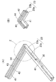
図4(A)及び図4(B)はフレーム23の構造を示す斜視図であって、図4(A)は図3のY部を拡大して表し、図4(B)は図4(A)のZ部を異なる方向から見た様子を表している。このフレーム23は、枠状をした内側フレーム部23a(第1フレーム部)の外周面に外側フレーム部23b(第2フレーム部)を枠状に一体成形したものである。内側フレーム部23aは、光反射率の高い樹脂材料、すなわち白色樹脂(酸化チタンの微粉末を添加してあってもよい。)によって角枠状に成形されている。外側フレーム部23bは、光吸収率の高い樹脂材料、すなわち黒色樹脂によって角枠状に形成されている。したがって、フレーム23の4辺において、フレーム23は白色樹脂からなる内側フレーム部23aと黒色樹脂からなる外側フレーム部23bの複合構造となっている。
4 (A) and 4 (B) are perspective views showing the structure of the
内側フレーム部23aは、光源配置側の辺を除く3辺においては、その上面42の内周縁を一段低くして段部41を形成されている。また、内側フレーム部23aの光源配置側の辺は、その上面全体が段部41と同じ高さとなっている。外側フレーム部23bは、その上面43の外周側の縁に沿って4辺にリブ44が突出している。外側フレーム部23bの下面から上面43までの高さと、内側フレーム部23aの下面から上面42までの高さは等しくなっており、外側フレーム部23bの上面43と内側フレーム部23aの上面42は面一になっている。また、外側フレーム部23bの光源配置側の辺には、フレキシブルプリント基板25の配線引出部25bを通過させるための切欠部30が設けられており、切欠部30の底面は内側フレーム部23aの段部41と面一になっている。
The
このフレーム23は、内側フレーム部23aと外側フレーム部23bを2色成形法によって一体成形されている。図8は、フレーム23を2色成形するための2色成形機51の構造を説明するための概念図である。この2色成形機51は、回転軸52を中心として回転可能で、かつ、昇降可能となった下金型53と、下金型53の上面に対向するように配置された2種の上金型54、55によって構成されている。下金型53には、フレーム23すなわち内側フレーム部23a及び外側フレーム部23bを成形するためのキャビティ56が複数箇所に形成されている。一方の上金型54は、下金型53のキャビティ56のうち内側フレーム部23aを成形するための空間を埋めて塞ぐための型部57を有している。また、上金型54は、外側フレーム部23bを成形するための空間(キャビティ56のうち型部57で塞がれていない成形空間)へ黒色樹脂を注入するための湯道58を備えている。他方の上金型55は、キャビティ56のうち内側フレーム部23aを成形するための空間へ白色樹脂を注入するための湯道59を備えている。
In this
フレーム23は、この2色成形機51を用いて次のようにして成形される。まず、図8の向かって左側の成形位置では、上金型54が下降して下金型53のキャビティ56が閉じられると、型部57によって内側フレーム部23aの成形空間が塞がれる。よって、湯道58からキャビティ56内に流動状態の黒色樹脂が注入されると、黒色樹脂によって外側フレーム部23bが射出成形される。下金型53が下降して型開きされると、キャビティ56内には外側フレーム部23bが成形されており、またその内側には内側フレーム部23aを成形するための空間が空いている。
The
ついで、下金型53を回転させ、外側フレーム部23bを保持したキャビティ56を図8の向かって右側の成形位置へ移動させる。この位置で下金型53を上昇させてキャビティ56を閉じ、湯道59からキャビティ56内に流動状態の白色樹脂を注入すると、白色樹脂によって内側フレーム部23aが外側フレーム部23bと一体成形される。なお、このとき同時に、反対側の位置では、上金型54によって外側フレーム部23bが成形されている。
Next, the
ついで、下金型53が下降して型開きされ、内側フレーム部23aと外側フレーム部23bが硬化してフレーム23が一体成形されると、下金型53からイジェクトピン(図示せず)が突出してフレーム23がキャビティ56から取り出される。こうして空になったキャビティ56は、下金型53を回転させることによって始めの位置に戻される。
Next, when the
なお、図8の2色成形機51では、外側フレーム部23bを成形した後に内側フレーム部23aを成形する構造となっていたが、内側フレーム部23aを成形した後で外側フレーム部23bを成形するようになっていてもよい。
In the two-
つぎに、上記面光源装置21の組立て時の構造を図5〜図7により説明する。図5(A)は組み立てられた面光源装置21の平面図、図5(B)は遮光シート28及び光学シート27a、27b、27cを除いた状態の平面図である。また、図6は図5(A)のV−V線に沿った断面の拡大図、図7はW−W線に沿った断面の拡大図である。
Next, the structure when the surface
図6及び図7に示すように、反射シート22は、その外周部を両面粘着テープ29によってフレーム23の下面に接着され、フレーム23内の空間はその下面を反射シート22によって塞がれる。導光板24は、フレーム23内に納めて反射シート22の上に載置される。図6に示すように、光源26は、発光窓を導光板24の光入射端面24aに対向させるようにしてフレーム23内に納められ、フレキシブルプリント基板25の配線引出部25bは、切欠部30を通過してフレーム23の外側へ引き出される。図5(B)はこのときの状態を示す。さらに、導光板24の光出射面24bの上には拡散シート27aとプリズムシート27b、27cが重ねられる。プリズムシート27cの上には遮光シート28が重ねられ、遮光シート28の下面がフレーム23に貼り付けられる。導光板24や拡散シート27a、プリズムシート27b、27cの周囲は遮光シート28で覆われ、導光板24の有効発光領域に対応する領域が開口窓31から露出させられる。
As shown in FIGS. 6 and 7, the
遮光シート28は、フレーム23の光源配置側の辺では、図6に示すように、外側フレーム部23bの上面43に接着され、フレーム23の光源配置側を除く3辺では、図7に示すように、外側フレーム部23bの上面43及び内側フレーム部23aの上面42に接着される。
As shown in FIG. 6, the
近年、面光源装置21の薄型化によってフレーム23の厚み(断面の幅)も薄くなっているので、薄型の面光源装置向けのフレーム23では内側フレーム部23aと外側フレーム部23bの接合面23c(成形時の接合面)の面積はかなり小さくなる。そのため、フレーム23の接合面23cは、外部からの負荷などによって剥がれるおそれがある。しかし、図7に示すように、接合面23cを跨がせて内側フレーム部23aの上面42と外側フレーム部23bの上面43に遮光シート28を接着しておけば、遮光シート28で内側フレーム部23aと外側フレーム部23bをつないで両フレーム部23a、23bどうしの剥離強度を高めることができる。同様に、反射シート22を接着するための両面粘着テープ29も、接合面23cを跨がせて内側フレーム部23aの下面と外側フレーム部23bの下面に接着しておけば、内側フレーム部23aと外側フレーム部23bの剥離強度をさらに高めることができる。
In recent years, the thickness (cross-sectional width) of the
このようにして組み立てられた面光源装置21では、フレーム23内に納められた導光板24、フレキシブルプリント基板25及び光源26、拡散シート27a及びプリズムシート27b、27cは遮光シート28と反射シート22の間に保持される。なお、図6及び図7では、遮光シート28の下面とプリズムシート27cやフレキシブルプリント基板25との間に隙間が存在しているが、遮光シート28の下面はプリズムシート27cの縁やフレキシブルプリント基板25に接着させて遮光シート28によりプリズムシート27cなどを固定することが好ましい。
In the surface
こうして遮光シート28をフレーム23に貼り付けた状態では、遮光シート28の上にリブ44で囲まれた空間33(凹所)ができている。液晶パネル(図示せず)は、この空間33内に納めて保持させることができる。
When the
このような構造の面光源装置21にあっては、図6に矢印で示すように、光源26から出射した光は、光入射端面24aから導光板24内に入射する。導光板24内に入射した光は、導光板24の上面(光出射面24b)と下面で全反射しながら導光板24内を導光し、導光板24の全体に広がっていく。また、導光板24の下面には、プリズム状をした微小な光学パターン32(導光板24の下面を窪ませた三角柱状の微小パターン、あるいは導光板24の下面から突出した三角柱状の微小パターンなど)が多数形成されている。そのため、導光板24内を導光する光が光学パターン32に入射して光学パターン32で全反射されると、反射した光は導光板24の光出射面24bから出射する。このようにして光出射面24bから出射する光の指向特性は比較的狭いので、拡散シート27aを透過させることによって緩やかに光を拡散させ、指向特性を広げる。さらに、プリズムシート27b、27cを透過させることによって光の方向を曲げ、最大輝度方向が光出射面24bに垂直な方向に近くなるようにしている。
In the surface
また、反射シート22は、導光板24の下面から漏れた光を反射させて導光板24内に再入射させ、光の利用効率を高める働きをする。
In addition, the
本実施形態の面光源装置21にあっては、光出射面24bから出射しないで導光板24の端面や両側面に達した光の一部は、図7に示すように導光板24の端面や両側面から漏れるが、漏れた光は白色樹脂からなる内側フレーム部23aの内周面で反射され、導光板24内へ再入射する。したがって、面光源装置21の光利用効率を向上させることができ、光出射面24bの発光輝度を高めることができる。しかも、内側フレーム部23aの内周面で反射されないで内側フレーム部23aを透過した光は、黒色樹脂からなる外側フレーム部23bに吸収される。よって、内側フレーム部23aを透過した光がフレーム23の外部へ漏れにくくなり、面光源装置21の縁を光らせて面光源装置21の品質を低下させにくくなり、また、近くに配置された光センサや受光部を誤動作させにくくなる。よって、面光源装置21によれば、フレーム23の厚みが薄くなった場合でも、光利用効率を高めて発光面の輝度を高くでき、しかも、周囲に光が漏れにくくなって、面光源装置21の品質が向上する。
In the surface
ここで、内側フレーム部23aの厚みがあまり薄いと、内側フレーム部23aの内周面により光を反射させにくくなり、光の利用効率が低下する。また、外側フレーム部23bの厚みがあまり薄いと、外側フレーム部23bで光を吸収しにくくなり、光の漏れが増加する。したがって、内側フレーム部23aの厚みと外側フレーム部23bの厚みは、いずれもあまり薄くなりすぎないようにして、適度の厚み比(たとえば、1:1)とすることが望ましい。しかし、好ましい厚み比は、内側フレーム部23aの材質(光反射率)や外側フレーム部23bの材質(光吸収率)によって異なるうえ、光反射率の高い内側フレーム部23aや光吸収率の高い外側フレーム部23bを用いれば、その許容範囲はかなり広くなる。よって、内側フレーム部23aと外側フレーム部23bの厚み(厚み比)は、それらの材質に応じて実験的に、あるいはシミュレーションにより決定すればよく、内側フレーム部23aの方が厚くてもよく、外側フレーム部23bの方が厚くてもよい。
Here, if the thickness of the
また、内側フレーム部23aは、コストを考慮したうえで、できるだけ光反射率の高い樹脂が好ましく、外側フレーム部23bも、コストを考慮したうえで、できるだけ光吸収率の高い樹脂が望ましい。特に、フレーム23の厚みが薄くなれば、できるだけ光反射率の高い材質の内側フレーム部23aと、光吸収率の高い材質の外側フレーム部23bを用いることが望ましい。
The
本実施形態のフレーム23では、内側フレーム部23aと外側フレーム部23bが一体成形されているので、面光源装置21の組立工程において、内側フレーム部23aと外側フレーム部23bが分離するおそれがなく、そのため面光源装置21の組立工程におけるトラブルが少なくなり、組立工程の効率化が図られる。
In the
また、フレームで光を反射させるとともに光の漏れを防止する方法としては、黒色樹脂からなるフレームの内周面に金属の蒸着膜やメッキ被膜などを施す方法も考えられる。しかし、このような方法では、蒸着膜やメッキ被膜を形成するためのコストが高くつくうえに、蒸着膜やメッキ被膜が剥がれるおそれがあり、信頼性や品質に問題がある。これに対し、本実施形態1のフレーム23では、光反射率の高い樹脂(内側フレーム部23a)と光吸収率の高い樹脂(外側フレーム部23b)との2色形成によって構成されているので、コストを安価にすることができ、また、剥離などの問題がなく信頼性が高い。
In addition, as a method of reflecting light by the frame and preventing light leakage, a method of applying a metal vapor-deposited film or a plating film to the inner peripheral surface of the frame made of black resin is also conceivable. However, in such a method, the cost for forming the vapor deposition film or the plating film is high, and the vapor deposition film or the plating film may be peeled off, which causes a problem in reliability and quality. On the other hand, the
また、図6及び図7に示すように、遮光シート28を外側フレーム部23bの上面43に接着させて内側フレーム部23aが遮光シート28で覆われるようにしてあれば、内側フレーム部23a内に入った光が内側フレーム部23aの上面から漏れて迷光となるのを防ぐことができる。
Further, as shown in FIGS. 6 and 7, if the
[第2の実施形態]
図9は、本発明の実施形態2に係る面光源装置81の一部を拡大して示す断面図である。実施形態1の面光源装置81では、内側フレーム部23aと外側フレーム部23bの間の接合面23cは、フレーム23の下面に垂直な面となっていたが、実施形態2では、内側フレーム部23aと外側フレーム部23bの間の接合面23cは、フレーム23の下面に垂直な面から傾いている。図9では、接合面23cは、上方にいくほど内側フレーム部23aの厚みが大きくなるように(あるいは、上方にいくほど外側フレーム部23bの厚みが小さくなるように)傾斜しているが、これとは逆に、上方にいくほど内側フレーム部23aの厚みが小さくなるように(あるいは、上方にいくほど外側フレーム部23bの厚みが大きくなるように)接合面23cが傾斜していてもよい。また、フレーム23の4辺すべてで接合面23cが傾いていることが望ましいが、一部の辺だけで接合面23cが傾いていても差し支えない。
[Second Embodiment]
FIG. 9 is an enlarged cross-sectional view of a part of the surface
フレーム23の高さが小さい場合には、接合面23cの面積を大きくとれないので、内側フレーム部23aと外側フレーム部23bが剥離しやすくなるが、フレーム23の高さが同じであっても、接合面23cを傾ければ接合面23cの面積を大きくできる。したがって、内側フレーム部23aと外側フレーム部23bの接着強度が大きくなり、外部からの負荷などによって内側フレーム部23aと外側フレーム部23bが剥離しにくくなる。また、図9のように傾いていれば、光学シート27a、27b、27cなどが乗っている内側フレーム部23aの重量を接合面23cで受けることができ、内側フレーム部23aと外側フレーム部23bがより剥離しにくくなる。
When the height of the
なお、この実施形態でも、遮光シート28は、接合面23cを跨いで内側フレーム部23aの上面42と外側フレーム部23bの上面43に接着されていることが好ましい。
In this embodiment, the
[第3の実施形態]
図10(A)は、本発明の実施形態3に係る面光源装置82の一部を拡大して示す断面図である。この実施形態では、外側フレーム部23bのリブ44を無くして外側フレーム部23bの上面43を平坦にしている。このような実施形態によれば、リブ44によって液晶パネルのサイズが制約されないので、面光源装置82の用途が拡大する。
[Third Embodiment]
FIG. 10A is an enlarged cross-sectional view showing a part of the surface
なお、図10(B)に示す面光源装置83のように、接合面23cが傾いたフレーム23において外側フレーム部23bのリブ44を無くしてもよい。
Note that, as in the surface
[第4の実施形態]
図11(A)は、本発明の実施形態4に係る面光源装置に用いられるフレーム23の一部を示す斜視図である。図11(B)は、当該フレーム23の一部を示す分解斜視図である。図11(C)は、当該フレーム23の一部を示す平面図である。
[Fourth Embodiment]
FIG. 11A is a perspective view showing a part of the
この実施形態では、一体成形されたフレーム23の一部、たとえば枠状をしたフレーム23の両側部において、内側フレーム部23aと外側フレーム部23bの接合面23cが、垂直上方から見たときに一直線とならないように屈曲または湾曲させている。図示例では、接合面23cにおいて、内側フレーム部23aに矩形状の凸部61を形成し、外側フレーム部23bに凸部61と噛み合う凹部62を形成している。これとは反対に、接合面23cにおいて、内側フレーム部23aに矩形状の凹部を形成し、外側フレーム部23bに凸部を形成してもよい。また、この凸部や凹部は、V形(三角形状)や丸形(円弧状)など任意の形状とすることが可能である。
In this embodiment, the
このように接合面23cの全体又は一部をジグザグに形成すれば、接合面23cの面積を増加させることができるので、内側フレーム部23aと外側フレーム部23bの接着強度が増して剥離が起こりにくくなる。また、この実施形態では、接合面23cの水平断面は、フレーム23の上面から下面まで同じ形状となっているので、フレーム23を成形するための2色成形機の金型構造を単純にすることができる。
If the entire or a part of the
[第5の実施形態]
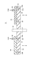
図12(A)及び図12(B)は、本発明の実施形態5に係る面光源装置84の異なる位置における断面を示す図である。また、図13は当該面光源装置84に用いられているフレーム23の一部を示す分解斜視図である。
[Fifth Embodiment]
FIGS. 12A and 12B are views showing cross sections at different positions of the surface
この面光源装置84に用いられているフレーム23においては、その大部分で、図12(B)に示すように接合面23cが平らになっているが、一部の接合面23cでは、図12(A)及び図13に示すように、突起63と窪み64が形成されている。すなわち、図13に示すように、外側フレーム部23bの接合面23cに上下一対の突起63が形成され、内側フレーム部23aの接合面23cに上下一対の窪み64が形成され、各突起63が各窪み64に嵌り込むように内側フレーム部23aと外側フレーム部23bが一体成形されている。
In most of the
このような面光源装置84では、外側フレーム部23bの突起63が内側フレーム部23aの窪み64に嵌合しているので、フレーム23が破損しないかぎり内側フレーム部23aと外側フレーム部23bが分離することがなく、面光源装置組立作業が容易になり、フレーム23の耐久性も向上する。
In such a surface
このような構造のフレーム23を2色成形機によって一体成形するには、たとえば図14(A)に示すように、フレーム23を成形するためのキャビティ56のうち外側フレーム部23bの成形空間を埋めておくための型部を2つの型部65a、65bに分けておく。そして、内側フレーム部23aを成形した後、図14(B)に示すように、カム機構(図示せず)によって型部65a、65bをそれぞれ上下にスライドさせれば、キャビティ56内に外側フレーム部23bを成形するための空間を空けることができる。なお、この方式においては、型部65aを上金型54の下面と一体に形成しておき、型部65bだけをカム機構で動かすようにすれば、2色成形機の構造をより簡単にすることができる。また別な方式としては、内側フレーム部23a又は外側フレーム部23bを成形するための空間を埋める型部をスライド機構によって水平方向にスライドさせるようにしてもよい。
In order to integrally form the
図15(A)及び図15(B)は、実施形態5の変形例による面光源装置85の異なる位置における断面を表している。この変形例では、図16に示すように、外側フレーム部23bに設けられた上の突起63と下の突起63の位置が、外側フレーム部23bの長さ方向にずれている。同様に、内側フレーム部23aに設けられた上の窪み64と下の窪み64の位置も、内側フレーム部23aの長さ方向にずれている。
15A and 15B show cross sections at different positions of the surface
なお、図示例では、外側フレーム部23bに突起63を設け、内側フレーム部23aに窪み64を設けているが、これとは反対に、外側フレーム部23bに窪み64を設け、内側フレーム部23aに突起63を設けてもよい。
In the illustrated example, the
[第6の実施形態]
図17は、本発明の実施形態6による面光源装置に用いるフレーム23を示す平面図である。このフレーム23では、白色樹脂の内側フレーム部23aは光源配置側から遠い側の辺と両側辺だけに設けられていて、フレーム23の光源配置側の辺は黒色樹脂の外側フレーム部23bだけで構成されている。したがって、内側フレーム部23aと外側フレーム部23bの複合構造も光源配置側から遠い側の辺と両側辺だけになっている。
[Sixth Embodiment]
FIG. 17 is a plan view showing a
この実施形態の効果を説明するため、まず、光源配置側における光の漏れを評価するために行った実験及びシミュレーションを説明する。光源配置側の辺を黒色樹脂のみで形成し、他の3辺を白色樹脂のみで形成したフレームを用意し、このフレームを用いた面光源装置において、発光面の25点(計測ポイント数)で輝度を計測し、その平均輝度を求めたところ97%であった。ただし、4辺が白色樹脂のフレームを用いた同じ構造の面光源装置において、発光面の25点で輝度を計測したときの平均輝度を基準(100%)とした。また、4辺が白色樹脂のフレームを用いた同じ面光源装置において、発光面の289点で輝度を計測したときの平均輝度を100%とすると、光源配置側の辺を黒色樹脂のみで形成し、他の3辺を白色樹脂のみで形成したフレームを用いた同じ構造の面光源装置において、289点で計測したときの平均輝度は97%であった。さらに、4辺が白色樹脂のフレームを用いた同じ面光源装置において、発光面の25点で輝度をシミュレーションしたときの平均輝度を100%とすると、光源配置側の辺を黒色樹脂のみで形成し、他の3辺を白色樹脂のみで形成したフレームを用いた同じ構造の面光源装置において、シミュレーションにより計算した25点の輝度の平均は99%であった。よって、この実験及びシミュレーションによれば、導光板24の外周面のうち、光源26と対向している面(光入射端面24a)から漏れる光はきわめて少ないことが分かる。
In order to explain the effect of this embodiment, first, experiments and simulations performed to evaluate light leakage on the light source arrangement side will be described. Prepare a frame in which the side on the light source arrangement side is formed of only black resin and the other three sides are formed of only white resin. In a surface light source device using this frame, 25 points on the light emitting surface (number of measurement points) The luminance was measured and the average luminance was determined to be 97%. However, in a surface light source device having the same structure using a white resin frame on four sides, the average luminance when luminance was measured at 25 points on the light emitting surface was used as a reference (100%). Further, in the same surface light source device using a white resin frame on four sides, assuming that the average luminance when the luminance is measured at 289 points on the light emitting surface is 100%, the side on the light source arrangement side is made of only black resin. In the surface light source device having the same structure using the frame in which the other three sides were formed only from white resin, the average luminance when measured at 289 points was 97%. Further, in the same surface light source device using a white resin frame on four sides, assuming that the average luminance when the luminance is simulated at 25 points on the light emitting surface is 100%, the side on the light source arrangement side is formed only with black resin. In the surface light source device having the same structure using the frame in which the other three sides are formed only from the white resin, the average of the luminance at 25 points calculated by simulation was 99%. Therefore, according to this experiment and simulation, it can be seen that very little light leaks from the surface (light
よって、図17に示す実施形態6のフレーム23のように、光源配置側では白色樹脂の内側フレーム部23aは省略していても光のロスは小さく、光の利用効率をほとんど低下しない。
Therefore, as in the
なお、これとは反対に、部分的に黒色樹脂の欠けた部分があっても差し支えない場合もある。たとえば、面光源装置の右側には光センサや受光部などがなく、多少の光が漏れても差し支えないような場合には、フレームの右側の辺を白色樹脂のみで形成していてもよい(ここから漏れる光は、白色樹脂で反射される透過した光であるから、ここからの漏れ光は面光源装置の光利用効率には影響がない。)。また、光源側の辺を白色樹脂のみで形成することも可能である。 In contrast to this, there may be a case where a black resin part is partially missing. For example, when there is no optical sensor or light receiving unit on the right side of the surface light source device and there is no problem even if some light leaks, the right side of the frame may be formed of only white resin ( Since the light leaking from here is transmitted light reflected by the white resin, the leaked light from here does not affect the light utilization efficiency of the surface light source device. It is also possible to form the light source side with only white resin.
[第7の実施形態]
図18は、本発明の実施形態7による面光源装置に用いるフレーム23を示す分解斜視図である。このフレーム23は、白色樹脂からなる内側フレーム部23aと黒色樹脂からなる外側フレーム部23bによって構成されているが、内側フレーム部23aと外側フレーム部23bは一体成形でなく、別々に成形されている。
[Seventh Embodiment]
FIG. 18 is an exploded perspective view showing the
このように内側フレーム部23aと外側フレーム部23bが別個になっていると、フレーム部23a、23bどうしを嵌め合わせるのが難しく、また、嵌め合わせた後も、導光板などの納入時に分離するおそれがあって、組立性が悪くなる。そのため、以下のようにして組み立てればよい。
If the
まず、図19(A)に示すように、外側フレーム部23bを裏返しにして置き、上から外側フレーム部23b内に内側フレーム部23aを納める。このとき、内側フレーム部23aの外周面23dと外側フレーム部23bの内周面23eにテーパーを施しておけば、外側フレーム部23b内に内側フレーム部23aを嵌め込みやすくなり、また、テーパーによって内側フレーム部23aが外側フレーム部23b内に保持される。
First, as shown in FIG. 19A, the
ついで、図19(B)に示すように、フレーム23の下面全周にわたって内側フレーム部23aの下面と外側フレーム部23bの下面に両面粘着テープ29を接着し、両面粘着テープ29によってフレーム23の下面に反射シート22の周囲を貼り付ける。この結果、内側フレーム部23aと外側フレーム部23bは両面粘着テープ29によって結合され、フレーム23が一体に保持される。なお、内側フレーム部23aの外周面23dと外側フレーム部23bの内周面23eを接着剤で接着することも考えられるが、この方法は接着剤の塗布が難しく、また、養生時間も必要になるが、反射シート22を貼り付けるための両面粘着テープ29により内側フレーム部23aと外側フレーム部23bを簡略な工程により一体化させることができる。
Next, as shown in FIG. 19B, a double-sided
この後、フレーム23を反転させて表向きに置き、フレーム23内に導光板24や光源26、光学シート27a、27b、27cを納め、内側フレーム部23aの上面42と外側フレーム部23bの上面43に遮光シート28を接着し、遮光シート28によりさらに内側フレーム部23aと外側フレーム部23bをさらに結合させる。
Thereafter, the
また、内側フレーム部23aと外側フレーム部23bの結合強度が増すように、図11に示したような凸部61及び凹部62や、図13又は図16に示したような突起63及び窪み64などを両フレーム部23a、23bに設けてもよい。
Further, in order to increase the coupling strength between the
なお、上記各実施形態においては、携帯電話に用いられる面光源装置を説明したが、本発明の面光源装置は、電子辞書、携帯用音楽プレーヤ、タブレット型コンピュータなどの液晶表示部などにも用いることができる。 In each of the above embodiments, the surface light source device used for the mobile phone has been described. However, the surface light source device of the present invention is also used for a liquid crystal display unit of an electronic dictionary, a portable music player, a tablet computer, or the like. be able to.
21、81〜85 面光源装置
22 反射シート
23 フレーム
23a 内側フレーム部
23b 外側フレーム部
23c 接合面
24 導光板
25 フレキシブルプリント基板
26 光源
27a 拡散シート
27b、27c プリズムシート
28 遮光シート
29 両面粘着テープ
61 凸部
62 凹部
63 突起
64 窪み
21, 81-85 Surface
Claims (23)
光源と、
前記導光板の外周面を囲むようにして前記光源及び前記導光板を収容するフレームと、を有し、
前記光源から出た光が前記導光板の端面から前記導光板内に入射し、前記導光板内を導光する光が前記導光板の光出射面から出射する面光源装置において、
前記フレームは、少なくともその一辺が、前記フレームの内周面をなすと共に光反射性材料からなる第1フレーム部と、前記第1フレーム部の外周面を覆う光吸収性材料からなる第2フレーム部とによって構成され、
前記第1フレーム部の外周面と前記第2フレーム部の内周面とが接する接合面の少なくとも一部が、前記第1フレームの内周面に対して傾いていることを特徴とする面光源装置。 A light guide plate;
A light source;
Anda frame for accommodating the light source and the light guide plate and the outer peripheral surface of the light guide plate to enclose useless,
In the surface light source device in which light emitted from the light source enters the light guide plate from an end surface of the light guide plate, and light guided in the light guide plate is emitted from the light exit surface of the light guide plate.
The frame has at least one side forming an inner peripheral surface of the frame and a first frame portion made of a light-reflective material, and a second frame portion made of a light-absorbing material that covers the outer peripheral surface of the first frame portion. And consists of
A surface light source characterized in that at least a part of a joint surface where the outer peripheral surface of the first frame portion and the inner peripheral surface of the second frame portion are in contact with each other is inclined with respect to the inner peripheral surface of the first frame. apparatus.
前記フレームのうち前記光源にもっとも近い辺を除くすべての辺が、前記第1フレーム部と前記第2フレーム部を接合させて構成されていることを特徴とする、請求項1に記載の面光源装置。 The frame has a rectangular frame shape,
2. The surface light source according to claim 1, wherein all sides of the frame except for a side closest to the light source are configured by joining the first frame part and the second frame part. apparatus.
少なくともその一辺が、前記フレームの内周面をなすと共に光反射性材料からなる第1フレーム部と、前記第1フレーム部の外周面を覆う光吸収性材料からなる第2フレーム部とによって構成され、
前記第1フレーム部の外周面と前記第2フレーム部の内周面とが接する接合面が、前記第1フレームの内周面に対して傾いていることを特徴とするフレーム。 The outer peripheral surface of the light guide plate enclose way a frame for a surface light source device for pay light source and the light guide plate,
At least one side of the frame is formed by a first frame portion made of a light-reflective material that forms the inner peripheral surface of the frame, and a second frame portion made of a light-absorbing material that covers the outer peripheral surface of the first frame portion. ,
A frame, wherein a joint surface where an outer peripheral surface of the first frame portion and an inner peripheral surface of the second frame portion are in contact with each other is inclined with respect to an inner peripheral surface of the first frame.
Priority Applications (3)
| Application Number | Priority Date | Filing Date | Title |
|---|---|---|---|
| JP2010198398A JP5521917B2 (en) | 2010-09-03 | 2010-09-03 | Surface light source device and frame used for surface light source device |
| US13/217,567 US8870438B2 (en) | 2010-09-03 | 2011-08-25 | Surface light source device with frame including light source and light guide plate |
| US14/463,357 US9599768B2 (en) | 2010-09-03 | 2014-08-19 | Surface light source device having frame with light absorbing and reflecting portions |
Applications Claiming Priority (1)
| Application Number | Priority Date | Filing Date | Title |
|---|---|---|---|
| JP2010198398A JP5521917B2 (en) | 2010-09-03 | 2010-09-03 | Surface light source device and frame used for surface light source device |
Related Child Applications (1)
| Application Number | Title | Priority Date | Filing Date |
|---|---|---|---|
| JP2014080391A Division JP5720828B2 (en) | 2014-04-09 | 2014-04-09 | Surface light source device |
Publications (2)
| Publication Number | Publication Date |
|---|---|
| JP2012059372A JP2012059372A (en) | 2012-03-22 |
| JP5521917B2 true JP5521917B2 (en) | 2014-06-18 |
Family
ID=45806569
Family Applications (1)
| Application Number | Title | Priority Date | Filing Date |
|---|---|---|---|
| JP2010198398A Active JP5521917B2 (en) | 2010-09-03 | 2010-09-03 | Surface light source device and frame used for surface light source device |
Country Status (2)
| Country | Link |
|---|---|
| US (2) | US8870438B2 (en) |
| JP (1) | JP5521917B2 (en) |
Cited By (1)
| Publication number | Priority date | Publication date | Assignee | Title |
|---|---|---|---|---|
| JPH069698Y2 (en) | 1988-01-26 | 1994-03-16 | 株式会社アマダ | Vendor with continuity type safety device |
Families Citing this family (31)
| Publication number | Priority date | Publication date | Assignee | Title |
|---|---|---|---|---|
| US8154680B2 (en) | 2010-04-15 | 2012-04-10 | Apple Inc. | Electronic device display structures with controlled chassis reflections |
| JP5521917B2 (en) * | 2010-09-03 | 2014-06-18 | オムロン株式会社 | Surface light source device and frame used for surface light source device |
| US9244215B2 (en) * | 2011-09-09 | 2016-01-26 | Apple Inc. | Chassis for display backlight |
| JP5530419B2 (en) * | 2011-11-25 | 2014-06-25 | ミネベア株式会社 | Planar illumination device and manufacturing method thereof |
| US9799242B2 (en) * | 2012-02-15 | 2017-10-24 | Sony Mobile Communications Inc. | Personal digital assistant apparatus |
| CN102620218A (en) * | 2012-04-18 | 2012-08-01 | 深圳市华星光电技术有限公司 | Backlight module and liquid crystal display device |
| WO2013184151A1 (en) * | 2012-06-08 | 2013-12-12 | Apple Inc. | Keyboard backlight features for a portable computer |
| US9239422B2 (en) | 2012-12-20 | 2016-01-19 | Apple Inc. | Light guide plate with blunt edges |
| CN103971624A (en) * | 2013-01-28 | 2014-08-06 | 富泰华工业(深圳)有限公司 | Light-leaking detection system and method |
| US20140211507A1 (en) * | 2013-01-31 | 2014-07-31 | Innolux Corporation | Electronic device |
| JP2014170067A (en) * | 2013-03-01 | 2014-09-18 | Funai Electric Co Ltd | Display device |
| WO2015008664A1 (en) * | 2013-07-19 | 2015-01-22 | 堺ディスプレイプロダクト株式会社 | Display device |
| US20160154172A1 (en) * | 2013-09-04 | 2016-06-02 | Sharp Kabushiki Kaisha | Lighting device and display device |
| KR102297074B1 (en) * | 2014-12-01 | 2021-09-01 | 엘지디스플레이 주식회사 | Liquid crystal display device |
| US20160187559A1 (en) * | 2014-12-31 | 2016-06-30 | Boe Technology Group Co., Ltd. | Display device |
| CN104534363A (en) * | 2014-12-31 | 2015-04-22 | 深圳市华星光电技术有限公司 | Backlight module and liquid crystal display with backlight module |
| USD776665S1 (en) * | 2015-02-05 | 2017-01-17 | Neonode Inc. | Light guide frame |
| JP6473816B2 (en) * | 2015-06-30 | 2019-02-20 | 堺ディスプレイプロダクト株式会社 | Display device |
| KR102429136B1 (en) * | 2015-10-30 | 2022-08-03 | 엘지디스플레이 주식회사 | Display device |
| KR102494154B1 (en) * | 2015-12-31 | 2023-01-31 | 엘지디스플레이 주식회사 | Liquid Crystal Display Device |
| CN105511172B (en) * | 2016-02-19 | 2019-05-03 | 武汉华星光电技术有限公司 | A liquid crystal display device |
| KR20170115223A (en) * | 2016-04-06 | 2017-10-17 | 삼성디스플레이 주식회사 | Display panel and display apparatus having the same |
| JP2017198854A (en) | 2016-04-27 | 2017-11-02 | 株式会社ジャパンディスプレイ | Lighting device and liquid crystal display |
| CN107966843B (en) * | 2016-10-20 | 2021-03-26 | 群创光电股份有限公司 | display device |
| JP6390733B2 (en) * | 2017-03-09 | 2018-09-19 | オムロン株式会社 | Frame, surface light source device, display device, and electronic device |
| JP7203366B2 (en) * | 2017-03-16 | 2023-01-13 | パナソニックIpマネジメント株式会社 | Display device |
| CN107991810B (en) * | 2017-12-27 | 2024-03-01 | 北京小米移动软件有限公司 | Backlight and liquid crystal display |
| WO2019224698A2 (en) | 2018-05-22 | 2019-11-28 | 3M Innovative Properties Company | Optical film with light control edge |
| WO2021051327A1 (en) * | 2019-09-18 | 2021-03-25 | 京东方科技集团股份有限公司 | Backlight module, display module, and display device |
| US11513383B2 (en) * | 2020-09-24 | 2022-11-29 | Apple Inc. | Electronic device display assembly |
| WO2023286380A1 (en) * | 2021-07-15 | 2023-01-19 | ミネベアミツミ株式会社 | Planar lighting device |
Family Cites Families (19)
| Publication number | Priority date | Publication date | Assignee | Title |
|---|---|---|---|---|
| JPH1152140A (en) | 1997-08-07 | 1999-02-26 | Enplas Corp | Sidelight type surface light source device |
| JP2001249324A (en) * | 2000-03-03 | 2001-09-14 | Hitachi Ltd | Liquid crystal display |
| KR100687536B1 (en) * | 2000-04-28 | 2007-02-27 | 삼성전자주식회사 | Backlight Assembly and LCD |
| KR100666321B1 (en) * | 2000-06-30 | 2007-01-09 | 삼성전자주식회사 | Stacked backlight assembly, liquid crystal display device using the same and assembly method thereof |
| TW540749U (en) * | 2001-11-30 | 2003-07-01 | Chi Mei Optoelectronics Corp | Fixing frame for backlight module |
| AU2002330301A1 (en) * | 2002-09-18 | 2004-04-08 | Matsushita Electric Industrial Co., Ltd. | Illumination unit and liquid crystal display comprising it |
| JP4151834B2 (en) * | 2002-09-25 | 2008-09-17 | シャープ株式会社 | Backlight unit and liquid crystal display device |
| KR100710168B1 (en) * | 2003-09-30 | 2007-04-20 | 엘지.필립스 엘시디 주식회사 | Liquid crystal display |
| KR100970268B1 (en) * | 2003-10-11 | 2010-07-16 | 삼성전자주식회사 | Back light assembly and display device having same |
| KR101203661B1 (en) * | 2005-10-14 | 2012-11-23 | 삼성디스플레이 주식회사 | Backlight assembly and liquid crystal display having the same |
| JP2008129240A (en) * | 2006-11-20 | 2008-06-05 | Sharp Corp | Liquid crystal display |
| KR101451737B1 (en) * | 2006-11-29 | 2014-10-16 | 엘지디스플레이 주식회사 | Liquid crystal display |
| JP3130253U (en) * | 2006-12-19 | 2007-03-22 | 宏塑工業股▲ふん▼有限公司 | Backlight module frame |
| CN101256299B (en) * | 2007-02-28 | 2010-05-26 | 群康科技(深圳)有限公司 | Back light module unit as well as display device using the same |
| JP2009301912A (en) * | 2008-06-14 | 2009-12-24 | Citizen Electronics Co Ltd | Back light unit and liquid crystal display |
| JP5262601B2 (en) * | 2008-11-14 | 2013-08-14 | セイコーエプソン株式会社 | Electro-optical device and electronic apparatus |
| US8154680B2 (en) * | 2010-04-15 | 2012-04-10 | Apple Inc. | Electronic device display structures with controlled chassis reflections |
| JP5521917B2 (en) * | 2010-09-03 | 2014-06-18 | オムロン株式会社 | Surface light source device and frame used for surface light source device |
| JP5530419B2 (en) * | 2011-11-25 | 2014-06-25 | ミネベア株式会社 | Planar illumination device and manufacturing method thereof |
-
2010
- 2010-09-03 JP JP2010198398A patent/JP5521917B2/en active Active
-
2011
- 2011-08-25 US US13/217,567 patent/US8870438B2/en not_active Expired - Fee Related
-
2014
- 2014-08-19 US US14/463,357 patent/US9599768B2/en not_active Expired - Fee Related
Cited By (1)
| Publication number | Priority date | Publication date | Assignee | Title |
|---|---|---|---|---|
| JPH069698Y2 (en) | 1988-01-26 | 1994-03-16 | 株式会社アマダ | Vendor with continuity type safety device |
Also Published As
| Publication number | Publication date |
|---|---|
| JP2012059372A (en) | 2012-03-22 |
| US8870438B2 (en) | 2014-10-28 |
| US20120063167A1 (en) | 2012-03-15 |
| US9599768B2 (en) | 2017-03-21 |
| US20140354918A1 (en) | 2014-12-04 |
| US20140307469A9 (en) | 2014-10-16 |
Similar Documents
| Publication | Publication Date | Title |
|---|---|---|
| JP5521917B2 (en) | Surface light source device and frame used for surface light source device | |
| JP5609466B2 (en) | Surface light source device and frame used for surface light source device | |
| JP5525442B2 (en) | Display device and manufacturing method thereof | |
| JP6527892B2 (en) | Borderless display including display module | |
| TWI431372B (en) | Surface light source device and liquid crystal display device | |
| US20130263488A1 (en) | Display device and assembly method thereof | |
| US20090273931A1 (en) | Illumination device and input unit with illumination device | |
| JP5211131B2 (en) | Backlight device and liquid crystal display device | |
| JPH10247412A (en) | Surface light source device | |
| JP6170257B2 (en) | LIGHTING DEVICE, DISPLAY DEVICE, AND LIGHTING DEVICE MANUFACTURING METHOD | |
| CN108153014B (en) | Display device | |
| JP2009163132A (en) | Method for manufacturing liquid crystal display device, liquid crystal display device, and electronic apparatus | |
| WO2014061572A1 (en) | Illumination device and display device | |
| WO2018051855A1 (en) | Optical member, illumination device, and display device | |
| JP5720828B2 (en) | Surface light source device | |
| KR101630342B1 (en) | Liquid crystal display device and mathod for manufacturing the same | |
| CN113847583A (en) | Light emitting module and electronic equipment | |
| JP4411186B2 (en) | Liquid crystal display | |
| KR101922062B1 (en) | Liquid Crystal Display device and Method for manufacturing the same | |
| CN100403118C (en) | Backlight module structure | |
| WO2022033234A1 (en) | Side-type light source, backlight module and display device | |
| CN116699891B (en) | Display screens and electronic devices | |
| CN108153059B (en) | Backlight module, display device and electronic equipment | |
| TWI437327B (en) | Back-light module | |
| CN224137590U (en) | Backlight module and display terminal |
Legal Events
| Date | Code | Title | Description |
|---|---|---|---|
| A621 | Written request for application examination |
Free format text: JAPANESE INTERMEDIATE CODE: A621 Effective date: 20130111 |
|
| A871 | Explanation of circumstances concerning accelerated examination |
Free format text: JAPANESE INTERMEDIATE CODE: A871 Effective date: 20130823 |
|
| A977 | Report on retrieval |
Free format text: JAPANESE INTERMEDIATE CODE: A971007 Effective date: 20131010 |
|
| A975 | Report on accelerated examination |
Free format text: JAPANESE INTERMEDIATE CODE: A971005 Effective date: 20131010 |
|
| A131 | Notification of reasons for refusal |
Free format text: JAPANESE INTERMEDIATE CODE: A131 Effective date: 20131022 |
|
| A521 | Written amendment |
Free format text: JAPANESE INTERMEDIATE CODE: A523 Effective date: 20131211 |
|
| TRDD | Decision of grant or rejection written | ||
| A01 | Written decision to grant a patent or to grant a registration (utility model) |
Free format text: JAPANESE INTERMEDIATE CODE: A01 Effective date: 20140311 |
|
| A61 | First payment of annual fees (during grant procedure) |
Free format text: JAPANESE INTERMEDIATE CODE: A61 Effective date: 20140324 |
|
| R150 | Certificate of patent or registration of utility model |
Ref document number: 5521917 Country of ref document: JP Free format text: JAPANESE INTERMEDIATE CODE: R150 |