JP5483134B2 - Method and apparatus for measuring volume of microdroplet - Google Patents
Method and apparatus for measuring volume of microdroplet Download PDFInfo
- Publication number
- JP5483134B2 JP5483134B2 JP2012224364A JP2012224364A JP5483134B2 JP 5483134 B2 JP5483134 B2 JP 5483134B2 JP 2012224364 A JP2012224364 A JP 2012224364A JP 2012224364 A JP2012224364 A JP 2012224364A JP 5483134 B2 JP5483134 B2 JP 5483134B2
- Authority
- JP
- Japan
- Prior art keywords
- liquid
- measurement
- volume
- physical property
- droplet
- Prior art date
- Legal status (The legal status is an assumption and is not a legal conclusion. Google has not performed a legal analysis and makes no representation as to the accuracy of the status listed.)
- Active
Links
Images




Landscapes
- Analysing Materials By The Use Of Radiation (AREA)
- Investigating, Analyzing Materials By Fluorescence Or Luminescence (AREA)
- Investigating Or Analysing Materials By Optical Means (AREA)
- Length Measuring Devices By Optical Means (AREA)
Description
本発明は、微量の液滴の体積を精度良くかつ正確に測定するのに適した微量液滴の体積の測定方法、およびその方法を実施する装置に関する。 The present invention relates to a method for measuring the volume of a minute droplet suitable for accurately and accurately measuring the volume of a minute droplet, and an apparatus for performing the method.
近年、チップ分析法や多検体迅速分析技術の目覚しい発展により、環境・バイオ分野における分析装置のハイスループット化が加速している。それに伴い、試料溶液の微量化が加速しており、微量試料溶液を微小領域に多検体溶液を塗布するニーズも増大している。実際、近年開発されている環境・バイオ分野における試料分注装置が取り扱う試料量は、従来のマイクロリットルレベルからナノリットルレベルないしピコリットルレベルへと、より微量化している。 In recent years, due to the remarkable development of chip analysis methods and rapid multi-analyte analysis technology, high-throughput analysis devices in the environmental and bio fields are accelerating. Accordingly, the amount of sample solution is accelerating, and the need for applying a multi-sample solution to a minute region is increasing. In fact, the amount of sample handled by the sample dispensing apparatus in the environmental / bio field that has been developed in recent years has decreased from the conventional microliter level to the nanoliter level or picoliter level.
このような背景において、分析試料を高精度かつ正確に取り分けることは、分析結果の信頼性に大きく影響するため、微量試料溶液を精度良く正確に測定する手法の重要性も高まりつつある。また、同分野におけるトレーサビリティの観点からも、微量試料溶液を取り扱う試料分注装置の測定体積の校正は、ますます重要性を増すものと考えられる。 In such a background, since the separation of analysis samples with high accuracy and accuracy greatly affects the reliability of analysis results, the importance of a method for accurately measuring a minute amount of sample solution is also increasing. In addition, from the viewpoint of traceability in this field, it is considered that calibration of the measurement volume of a sample dispensing apparatus that handles a small amount of sample solution will become increasingly important.
液滴の体積が大きい場合、従来法では水などの比重既知の液体の液滴を作成した後、この液滴の重量を測定することで、液滴の体積を求めている。この方法は、例えばマイクロピペットなどの、比較的大きな体積(0.5マイクロリットル以上)の液体を分注する機器の校正に広く使用されている。図1にこの方法の具体的手順を示した。すなわち、分注前および分注後の液体容器の重量(W1およびW2)と分注した液滴の個数nとから1個あたりの液滴重量wを求め、液体の比重rより液滴の体積Vを求める。または、分注した液体全体の重量Wを直接求め、同様の方法で液滴の体積Vを求める。この方法は、天秤など液滴の重量を測定する機器以外の特別な装置を用いることなく比較的容易に遂行可能であるが、測定中に液体の蒸発が起こるため液滴の正確な重量を測定することは難しく、特にその蒸発が無視できなくなるほど微量なナノリットルないしピコリットルレベルの液滴の場合には、この方法は適さない。 When the volume of the droplet is large, in the conventional method, a droplet of a liquid having a known specific gravity such as water is created, and then the weight of the droplet is measured to obtain the volume of the droplet. This method is widely used for calibration of instruments that dispense a relatively large volume (0.5 microliters or more) of liquid, such as a micropipette. FIG. 1 shows a specific procedure of this method. That is, the droplet weight w per one is obtained from the weight (W 1 and W 2 ) of the liquid container before and after dispensing and the number n of the dispensed droplets, and the droplet is determined from the specific gravity r of the liquid. Determine the volume V of. Alternatively, the weight W of the dispensed liquid is directly obtained, and the volume V of the droplet is obtained by the same method. This method can be performed relatively easily without using a special device other than a weighing instrument such as a balance. However, since the liquid evaporates during measurement, the exact weight of the droplet is measured. It is difficult to do this, and this method is not suitable particularly in the case of nanoliter or picoliter level droplets whose evaporation is negligible.
微量液滴の体積を求める他の方法として、インクジェット方式における吐出口から吐出した後の液滴の体積を、ストロボ、LED、レーザなどの光源を用い、パルス光で吐出口から飛び出している液滴を照明しながら顕微鏡で観察することによって測定する方法がある(例えば、特許文献1参照)。 As another method for obtaining the volume of a minute droplet, a droplet ejected from the ejection port by a pulse light using a light source such as a strobe, LED, laser, etc. There is a method of measuring by observing with a microscope while illuminating (see, for example, Patent Document 1).
この方法によれば、微量液滴の1個の体積を顕微鏡画像から測定することが可能であるが、吐出方向に対して直交する1方向ないし互いに直交する2方向からの外形寸法に基づいて液滴の断面形状を楕円で近似することにより体積を計算すること、顕微鏡画像撮影時に必要な光量を確保するため照射光パルス幅を0にできないこと、および微量液滴のため液体の蒸発が無視できないことから、誤差が生じやすかった。 According to this method, it is possible to measure one volume of a minute droplet from a microscopic image. However, the liquid droplets are measured based on external dimensions from one direction orthogonal to the ejection direction or from two directions orthogonal to each other. Calculating the volume by approximating the cross-sectional shape of the droplet with an ellipse, the pulse width of the irradiation light cannot be reduced to ensure the amount of light required for microscopic imaging, and the evaporation of liquid cannot be ignored due to the small amount of droplets As a result, errors were likely to occur.
微量液滴の体積を求める別の方法として、微量液滴を疎液体性表面で区切られた親液体性表面区域に付着させ、その区域内に全域に広がる液滴の三次元形状を光学式体積測定装置によって測定し、その三次元形状を積分することによって体積を計算する方法がある(例えば、特許文献2参照)。 Another way to determine the volume of a microdroplet is to attach a microdroplet to a lyophilic surface area delimited by a lyophobic surface and then use the optical volume to create a three-dimensional shape of the liquid droplet that extends throughout the area. There is a method of calculating a volume by measuring with a measuring device and integrating the three-dimensional shape (see, for example, Patent Document 2).
この方法によれば、親液体性表面区域内に形成された液滴の体積を前述のような形状近似を行うことなく直接的に測定することが可能であるが、親液体性表面区域全域を覆うのに比較的大きな液体体積を必要とするため、微量液滴1個の体積を求めることは困難である。また、微量液滴のため液体の蒸発が無視できないことから、誤差が生じやすかった。これは、基板上に滴下した微量液滴を撮像し、液滴と基板間の接触角や接触径等の数値から液滴体積を計算する手法(例えば、特許文献4参照)でも同様である。 According to this method, it is possible to directly measure the volume of the droplet formed in the lyophilic surface area without performing the shape approximation as described above. Since a relatively large liquid volume is required to cover, it is difficult to determine the volume of one minute droplet. Further, since the evaporation of the liquid cannot be ignored due to the small amount of droplets, an error is likely to occur. This also applies to a method (for example, refer to Patent Document 4) in which a minute droplet dropped on a substrate is imaged and the droplet volume is calculated from numerical values such as a contact angle and a contact diameter between the droplet and the substrate.
液体の蒸発をなるべく抑制するようにするため、シャーレ等に液滴を滴下した後に液滴に接するようにふたをすることで、液滴の大きさを規制し測定精度向上を図った微量液滴の体積測定法も報告されている(例えば、特許文献3参照)。しかし、液体がシャーレおよびふたとの間に残存する空気層へと蒸発することは避けられず、むしろ界面張力により液体の蒸発が促進されることで、測定誤差が生じやすい。これは、微量液滴を微細管に吸い込み、液滴が保持されている微細管の長さと断面積とから液滴の体積を計算する手法(例えば、特許文献5参照)でも同様である。 In order to suppress the evaporation of the liquid as much as possible, a small amount of liquid droplets that drop the droplets on a petri dish etc. and then touch the droplets to regulate the size of the droplets and improve the measurement accuracy The volume measurement method is also reported (for example, see Patent Document 3). However, it is inevitable that the liquid evaporates into the air layer remaining between the petri dish and the lid. Rather, the evaporation of the liquid is promoted by the interfacial tension, and measurement errors are likely to occur. The same applies to a method (for example, refer to Patent Document 5) in which a minute droplet is sucked into a microtube and the volume of the droplet is calculated from the length and cross-sectional area of the microtube in which the droplet is held.
液体の形状や光学的特徴に依存しない液滴の体積測定法の観点から、電場を形成した流路に液滴を通過させることで、電場における静電容量の変化から液滴の体積を求める方法(例えば、特許文献6)も提案されている。しかし、比較的大きな液滴体積を必要とし、液体の蒸発が無視できないため、微量液滴への適応は困難であった。 From the viewpoint of droplet volume measurement methods that do not depend on the shape or optical characteristics of the liquid, a method for determining the volume of a droplet from the change in capacitance in the electric field by passing the droplet through a flow path that forms an electric field. (For example, patent document 6) is also proposed. However, since a relatively large droplet volume is required and the evaporation of the liquid cannot be ignored, it is difficult to adapt to a small amount of droplets.
静電気力に基づきパルス印加により微量液滴を形成させる手法に基づく科学分野においては、ノズル−基板間にパルス電位を印加させた状態で粒子を含む液体の液滴をノズルから基板上に滴下し、滴下の際に流れる電荷量を積分することで液滴の体積を求める方法(例えば、特許文献7)がある。しかし、液滴の分注と同時に電荷量を測定する必要があるため、液滴にパルス電位を印加させる機構を装備した分注装置にしか適用することはできず、適用可能な液体も粒子を含む必要があるため、微量液滴の体積を測定する一般的な手法とは言い難い。 In the scientific field based on a technique of forming a minute droplet by applying a pulse based on electrostatic force, a liquid droplet containing particles is dropped from the nozzle onto the substrate while a pulse potential is applied between the nozzle and the substrate, There is a method (for example, Patent Document 7) for determining the volume of a droplet by integrating the amount of charge flowing during the dropping. However, since it is necessary to measure the amount of charge at the same time as the dispensing of the droplet, it can only be applied to a dispensing device equipped with a mechanism for applying a pulse potential to the droplet, and the applicable liquid also has particles. Since it is necessary to include, it is difficult to say that it is a general method for measuring the volume of a minute droplet.
水などの液体が一定量満たされたキュベットやマイクロタイタープレート等の小型容器内に、濃度既知の色素溶液を分注して希釈し、希釈前後の吸光度の変化から希釈倍率を求めることで分注した液滴の体積を求める方法がある。吸光光度計で測定するため、測定可能容量にメスアップする必要がある。しかし、希釈することで吸光度測定の誤差が大きくなることに加え、液体の蒸発が無視できないため、微量液滴への適応は困難であった。 Dispense and dilute a dye solution with a known concentration in a small container such as a cuvette or microtiter plate filled with a certain amount of liquid such as water, and determine the dilution ratio from the change in absorbance before and after dilution. There is a method for obtaining the volume of the liquid droplets. In order to measure with an absorptiometer, it is necessary to increase the volume to a measurable capacity. However, in addition to increasing the error in absorbance measurement due to dilution, the evaporation of the liquid cannot be ignored. Therefore, it is difficult to adapt to a minute droplet.
すなわち、精度良く微量液滴の体積を求めるには、従来法では液体の蒸発が無視できず誤差が生じやすかった。従って、液体の蒸発に無関係な微量液滴の体積の測定法が必要であるが、現状ではそのようは方法の開発はなされておらず、上述のいずれかの方法により微量液滴の体積を求めているのが実情である。 That is, in order to obtain the volume of a minute droplet with high accuracy, the conventional method cannot easily ignore the evaporation of the liquid, and an error is likely to occur. Therefore, there is a need for a method for measuring the volume of a minute droplet that is not related to the evaporation of the liquid. However, at present, such a method has not been developed, and the volume of a minute droplet is obtained by any of the above-described methods. It is the actual situation.
本発明は、以上のような事情に鑑みてなされたものであって、液体の蒸発に無関係に、精度良くかつ正確に微量液滴の体積を測定する方法およびその方法を実施する装置を提供することを目的とするものである。 The present invention has been made in view of the circumstances as described above, and provides a method for accurately and accurately measuring the volume of a minute droplet regardless of the evaporation of the liquid, and an apparatus for carrying out the method. It is for the purpose.
本発明者らは、上記目的を達成すべく鋭意研究を重ねた結果、検出可能な物性を有する濃度既知の標識物質を含む測定用液体を用いて液滴の分注を行い、分注した液滴内の標識物質の物性を検出するという方法によって、この液滴の体積を知るという上記目的が達成できるという知見を得た。また、液滴内の標識物質の物性検出を行う際に、液滴を載せるための測定用領域および必要であれば濃度を補正するための参照用領域を備えた基板を用い、参照用領域にて得られる物性値を基準とすることで、測定用領域の液滴に含まれる標識物質の絶対量が測定できることにより、上記目的が達成できるという知見を得た。 As a result of intensive studies to achieve the above object, the present inventors have dispensed droplets using a measurement liquid containing a labeled substance having a detectable physical property and a known concentration. It was found that the above-mentioned purpose of knowing the volume of the droplet can be achieved by a method of detecting the physical property of the labeling substance in the droplet. In addition, when detecting the physical properties of the labeling substance in the droplet, a substrate having a measurement region for placing the droplet and a reference region for correcting the concentration if necessary is used as the reference region. Based on the physical property values obtained in this way, the knowledge that the above object can be achieved by measuring the absolute amount of the labeling substance contained in the droplets in the measurement region was obtained.
本発明は前記のような技術思想によって課題を解決したものであるが、より具体的には次のようなものである。即ち、本発明に係る微量液体の体積測定方法は、前記課題を解決するため、検出可能な物性を有する濃度既知の標識物質を含む測定用液体を用いて液体の分注を行い、分注した液体内の標識物質の物性を検出することにより、分注後の微量液体の体積を測定することを特徴とする。 The present invention solves the problem by the technical idea as described above, but more specifically, is as follows. That is, in order to solve the above problems, the method for measuring a volume of a trace amount liquid according to the present invention dispenses a liquid by using a measurement liquid containing a labeling substance having a detectable physical property and having a known concentration. By detecting the physical properties of the labeling substance in the liquid, the volume of the trace liquid after dispensing is measured.
また、本発明に係る他の微量液体の体積測定方法は、前記微量液体の体積測定方法において、基板上に形成した複数の空間に標識物質を含む測定用液体を分注するとともに、一部の空間に標識物質のみの液体を入れ、前記分注した測定用液体中の標識物質の物性を検出するとともに、標識物質のみの液体の物性を検出し、両検出値により分注後の測定用液体の体積を測定することを特徴とする。 In addition, according to another volumetric liquid volume measuring method according to the present invention, in the volumetric liquid volume measuring method, a measuring liquid containing a labeling substance is dispensed in a plurality of spaces formed on a substrate. A liquid containing only the labeling substance is placed in the space, and the physical property of the labeling substance in the dispensed measurement liquid is detected, the physical property of the liquid containing only the labeling substance is detected, and the measurement liquid after dispensing based on both detection values It is characterized by measuring the volume of.
また、本発明に係る他の微量液体の体積測定方法は、前記微量液体の体積測定方法において、基板上に形成した複数の空間の一部を液体を含まない空間とし、前記標識物質の液体の物性検出時の参照用空間として用いることを特徴とする。 Further, in another volumetric liquid volume measuring method according to the present invention, in the volumetric liquid volume measuring method, a part of the plurality of spaces formed on the substrate is a space not including liquid, and the liquid of the labeling substance is It is used as a reference space when detecting physical properties.
前記測定用液体には分子量の大きな物質を添加し、測定用液体の蒸発速度を低下させることを特徴とする請求項1または2に記載の微量液滴の体積測定方法。 3. The method for measuring a volume of a minute droplet according to claim 1 or 2, wherein a substance having a large molecular weight is added to the measurement liquid to reduce the evaporation rate of the measurement liquid.
また、本発明に係る他の微量液体の体積測定方法は、前記微量液体の体積測定方法において、前記標識物質として吸光物質、蛍光物質、発光物質、または放射性同位体を用い、分注した液滴を搭載した基板をデンシトメータ、蛍光スキャナ、ルミノメータ、またはオートラジオグラフィを用いてイメージ化し、測定用液体内の標識物質から得られる吸光度、蛍光強度、発光強度、または放射線強度の物性値を画像として読み取り、標識物質のみの物性値と比較して測定用液体の体積を計算することを特徴とする。 Further, according to another method for measuring a volume of a minute liquid according to the present invention, a droplet dispensed using a light-absorbing substance, a fluorescent substance, a luminescent substance, or a radioisotope as the labeling substance in the method for measuring a volume of a minute liquid. Using a densitometer, a fluorescence scanner, a luminometer, or autoradiography, image a substrate equipped with, and read the physical properties of absorbance, fluorescence intensity, emission intensity, or radiation intensity obtained from the labeling substance in the measurement liquid as an image The volume of the liquid for measurement is calculated by comparing with the physical property value of only the labeling substance.
また、本発明に係る微量液体の体積測定装置は、基板上に複数の空間を形成し、前記空間の一部に標識物質を含む測定用液体を分注するとともに、他の一部の空間に標識物質のみの液体を入れ、前記分注した測定用液体中の標識物質の物性を検出するとともに、標識物質のみの液体の物性を検出し、両検出値により分注後の測定用液体の体積を測定することを特徴とする。 Moreover, the volume measuring device for a trace amount liquid according to the present invention forms a plurality of spaces on a substrate, dispenses a measuring liquid containing a labeling substance in a part of the space, and in another part of the space. Put the labeled substance only liquid, detect the physical properties of the labeled substance in the dispensed measurement liquid, detect the physical properties of the labeled substance only liquid, and the volume of the measured liquid after dispensing based on both detection values Is measured.
また、本発明に係る他の微量液体の体積測定装置は、前記微量液体の体積測定装置において、前記空間は前記基板とは別体に形成した隔壁の上下に貫通する複数の通孔であり、前記空間における基板側開口の周囲に形成した溝には、基板と接触する密封用Oリングを設けた治具を用いたことを特徴とする。 Further, in the volumetric measurement device for other trace liquid according to the present invention, in the volumetric measurement apparatus for the trace liquid, the space is a plurality of through holes penetrating up and down a partition wall formed separately from the substrate, The groove formed around the substrate side opening in the space is characterized by using a jig provided with a sealing O-ring in contact with the substrate.
また、本発明に係る他の微量液体の体積測定装置は、前記微量液体の体積測定装置において、前記空間の一部を液体を入れない空間とし、前記標識物質の液体の物性検出時の参照用空間として用いることを特徴とする。 Another volume measuring device for a small amount of liquid according to the present invention is the volume measuring device for a small amount of liquid, wherein a part of the space is a space that does not contain liquid, and is used for reference when detecting the physical properties of the liquid of the labeling substance. It is used as a space.
また、本発明に係る他の微量液体の体積測定装置は、前記微量液体の体積測定装置において、前記基板を導電性材料により形成し、電気化学活性物質を標識物質として用いることを特徴とする。 According to another aspect of the present invention, there is provided a trace liquid volume measuring apparatus, wherein the substrate is formed of a conductive material and an electrochemically active substance is used as a labeling substance.
また、本発明に係る他の微量液体の体積測定装置は、前記微量液体の体積測定装置において、前記隔壁の空間を密封する蓋を備え、前記標識物質のみを入れる空間には標識物質を全て充填して前記蓋により密封して光路長を規定する治具を用いたことを特徴とする。 Further, another volumetric liquid volume measuring device according to the present invention includes a lid for sealing the space of the partition wall in the volumetric liquid volume measuring device, and the space for containing only the labeling substance is filled with the labeling substance. Then, a jig that seals with the lid and defines the optical path length is used.
また、本発明に係る他の微量液体の体積測定装置は、前記微量液体の体積測定装置において、前記空間における基板側開口及び蓋側開口の周囲に形成した溝には、基板及び蓋にそれぞれ接触するOリングを設け、基板と隔壁と蓋とを前記隔壁を挟持する固定部材によりOリングを圧縮して一体化し固定したことを特徴とする。 According to another aspect of the invention, the volume measuring device for a small amount of liquid according to the present invention is such that the groove formed around the substrate side opening and the lid side opening in the space is in contact with the substrate and the lid, respectively. The O-ring is provided, and the substrate, the partition, and the lid are compressed and integrated and fixed by a fixing member that sandwiches the partition.
また、本発明に係る他の微量液体の体積測定装置は、前記微量液体の体積測定装置において、前記固定部材は、前記基板と蓋とを前記隔壁を挟持して固定するねじであることを特徴とする。 According to another aspect of the invention, the fixing member is a screw that fixes the substrate and the lid with the partition wall interposed therebetween. And
また、本発明に係る他の微量液体の体積測定装置は、前記微量液体の体積測定装置において、前記固定部材は、内部に前記基板と蓋とを前記隔壁を挟持した状態でスライドして収納できる空間を備えた容器であることを特徴とする。 According to another aspect of the present invention, there is provided a volumetric device for measuring a small amount of liquid. In the volumetric device for a small amount of liquid, the fixing member can be slid and housed with the substrate and the lid sandwiched therebetween. It is a container provided with a space.
また、本発明に係る他の微量液体の体積測定装置は、前記微量液体の体積測定装置において、前記隔壁を弾性材料により形成するとともに、自由状態時に該隔壁よりも高さの低い規定部材を設け、前記蓋による空間密封時に前記弾性材料の隔壁を圧縮し、該蓋を規定部材上面に密着することにより高さを規定して、光路長を規定することを特徴とする。 According to another aspect of the present invention, there is provided a volumetric device for measuring a small amount of liquid, wherein the partition wall is formed of an elastic material and a regulating member having a height lower than that of the partition is provided in a free state. The partition of the elastic material is compressed when the space is sealed by the lid, and the height is regulated by closely attaching the lid to the upper surface of the defining member, thereby defining the optical path length.
また、本発明に係る他の微量液体の体積測定装置は、前記微量液体の体積測定装置において、前記基板には前記空間内の液体の物性を測定する電極を備え、電気化学活性物質からなる標識物質の性情を測定可能にしたことを特徴とする。 In addition, according to another aspect of the present invention, there is provided a micro liquid volume measuring device, wherein the substrate is provided with an electrode for measuring physical properties of the liquid in the space, and is made of an electrochemically active substance. It is characterized by the fact that the nature of a substance can be measured.
また、本発明に係る他の微量液体の体積測定装置は、前記微量液体の体積測定装置において、前記電極は作用電極と対電極とを分離して形成したことを特徴とする。 According to another aspect of the present invention, there is provided a volumetric device for measuring a small amount of liquid, wherein the electrode is formed by separating a working electrode and a counter electrode.
本発明は以上のように構成したので、液体の蒸発に無関係な微量液滴の体積の測定を、精度良くかつ正確に実現することができる。 Since the present invention is configured as described above, it is possible to accurately and accurately realize the measurement of the volume of a minute droplet regardless of the evaporation of the liquid.
本発明は、液体の蒸発に無関係に、精度良くかつ正確に微量液滴の体積の測定を提供するという課題を、検出可能な物性を有する濃度既知の標識物質を含む測定用液体を用いて液滴の分注を行い、分注した液滴内の標識物質の物性を検出するという方法によって実現したものである。また、液滴内の標識物質の物性検出を行う際に、液滴を載せるための測定用領域および必要であれば濃度を補正するための参照用領域を備えた基板を用い、参照用領域にて得られる物性値を基準とすることで、測定用領域の液滴に含まれる標識物質の絶対量を測定することによって実現したものである。 The present invention solves the problem of accurately and accurately measuring the volume of a minute droplet regardless of the evaporation of the liquid by using a measuring liquid containing a labeling substance having a known physical property and having a detectable physical property. This is realized by a method of dispensing droplets and detecting physical properties of a labeling substance in the dispensed droplets. In addition, when detecting the physical properties of the labeling substance in the droplet, a substrate having a measurement region for placing the droplet and a reference region for correcting the concentration if necessary is used as the reference region. This is realized by measuring the absolute amount of the labeling substance contained in the droplets in the measurement region by using the physical property values obtained in this way as a reference.
本発明における測定のポイントは、分注から測定までの段階で分注した液滴の液体が蒸発したとしても、分注する液体に含まれる標識物質の濃度と分注した液滴に含まれる標識物質の絶対量とから、液滴体積を正確に計算できるところにある。標識物質としては、吸光物質、蛍光物質、発光物質、放射性同位体、電気化学活性物質などを挙げることができ、また、標識物質の検出可能な物性としては、吸光度、濁度、蛍光強度、発光強度、放射線強度、電荷量(電子数)などを挙げることができる。 The point of measurement in the present invention is that the concentration of the labeling substance contained in the liquid to be dispensed and the label contained in the dispensed droplet even if the liquid of the liquid dispensed in the stage from dispensing to measurement evaporates. The droplet volume can be accurately calculated from the absolute amount of the substance. Examples of labeling substances include light-absorbing substances, fluorescent substances, luminescent substances, radioisotopes, and electrochemically active substances. The detectable physical properties of labeling substances include absorbance, turbidity, fluorescence intensity, and luminescence. Intensity, radiation intensity, charge amount (number of electrons) and the like can be mentioned.
測定用液滴は、液体が蒸発することで液量が減少しても構わないし、また物性測定を容易にするため外部から液体を供給するなどして液量が増加しても構わない。蒸発速度を緩慢にするため、分子量の大きなアルコールやエーテル、糖、ペプチド、タンパク質などを添加しても良い。 The liquid droplets for measurement may decrease in liquid volume as the liquid evaporates, or the liquid volume may be increased by supplying liquid from the outside in order to facilitate physical property measurement. In order to slow down the evaporation rate, alcohol, ether, sugar, peptide, protein or the like having a large molecular weight may be added.
測定用基板は、標識物質の物性に影響を与えない材質であることが望ましい。例えば、吸光物質を標識物質として使用する際には光を吸収しないガラスや石英などの材質の基板を用いることが望ましく、電気化学活性物質を標識物質として使用する際には電気伝導性を有する金や白金などの材質の基板を用いることが望ましい。 The measurement substrate is preferably made of a material that does not affect the physical properties of the labeling substance. For example, when using a light-absorbing substance as a labeling substance, it is desirable to use a substrate made of a material such as glass or quartz that does not absorb light. When using an electrochemically active substance as a labeling substance, an electrically conductive metal is used. It is desirable to use a substrate made of a material such as platinum.
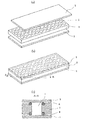
図2は、測定時に各液滴間での物性値が互いに干渉しないように、隔壁2などによって区切られた空間を有する測定用基板1の例である。この区切られた空間に各液滴を分注する。この隔壁2の材質としては、着色した石英・ガラス、樹脂、金属などを挙げることができる。例えば、吸光物質、蛍光物質、発光物質を標識物質として使用する際には、測定光が互いに干渉しないように、測定光を透過しない材質で作製された隔壁2を備えた基板1上に液滴を分注することが望ましい。
FIG. 2 is an example of the
測定用基板1と隔壁2は一体として作製しても良いし両者を別々に作製して合わせても良い。両者を別々に作製して合わせる場合には、図2(c)に示すように空間3の上下端周囲の溝にOリング4、6など樹脂製のパッキンを設けることが望ましい。隔壁2が樹脂製である場合にはこれに限らない。両者を分離することで、液滴の分注を様々な表面性状を持つ基板1上に行うことができる。例えば、実際に分注される液滴の体積は、測定用基板表面、分注装置の吐出口表面および測定用液体の3者間の表面張力に依存する。分注装置の分注精度を液滴体積から測定する場合には、測定用基板の種類に応じた分注精度を求めることが可能となる。
The
図3は、濃度を補正するための参照用領域を備えた測定用基板1の例である。例えば、吸光物質を標識物質として使用する際には、光路長が規定された参照用領域を少なくとも2箇所装備し、少なくとも1箇所(領域R)を測定用液体で満たし、他の少なくとも1箇所(領域B)をブランクとすることで、吸光度と標識物質の絶対量との関係を知ることができる。この関係を用いることで、液滴中の標識物質の絶対量を計算することができるため、液滴の体積を計算することができる。同様の方法は、蛍光物質、発光物質、放射性同位体を標識物質として用いた場合にも適用可能である。
FIG. 3 shows an example of the
図4は、上記参照用領域における光路長を規定するための治具の例である。隔壁2に対して蓋を被せることで、参照用領域に満たされた測定用液体の光路長を隔壁の高さにより規定する。隔壁2と蓋との密着性を高めるため、図4(c)に示すようにOリングなどの樹脂製のパッキンを介して合わせることが望ましい。測定用基板1と隔壁2の両者が分離している場合にも、パッキンを介して合わせることは同様に望ましい。隔壁2が測定用基板1に対して密着性の良い樹脂製である場合にはこれに限らない。
FIG. 4 is an example of a jig for defining the optical path length in the reference region. By covering the
図5は、上記参照用領域における光路長を規定するための治具の別の例である。隔壁が樹脂など容易に圧縮しうる軟質な材料で構成されている場合、硬質な材料で構成された参照用領域の光路長を規定する規定部材としての枠7を設け、この枠7の高さにより参照用領域の光路長を規定する。当該枠7の高さは隔壁2よりも低めに構成される。測定用基板1と当該枠7は一体として作製しても良いし、この例のように両者別々に作製して合わせても良い。
FIG. 5 is another example of a jig for defining the optical path length in the reference region. When the partition wall is made of a soft material that can be easily compressed, such as a resin, a
図6は、上記参照用領域における光路長を規定するための治具の別の例である。図4におけるパッキンを圧縮し、隔壁の高さにより参照用領域の光路長を規定するため、測定用基板1の垂直方向に対して圧力を掛けることで固定する。この例では4本のねじとしてのボルト9とナット10で留める形式になっているが、他の固定の仕方でも良い。
FIG. 6 is another example of a jig for defining the optical path length in the reference region. The packing in FIG. 4 is compressed and fixed by applying pressure to the vertical direction of the
図7は、上記参照用領域における光路長を規定するための治具の別の例である。この例では高さの規定された開口枠としての容器11に側方からスライドして挿入する形式になっているが、他の固定の仕方でも良い。
FIG. 7 is another example of a jig for defining the optical path length in the reference region. In this example, the
分注した液滴に含まれる標識物質の絶対量は、次のようにして求めることができる。標識物質が吸光物質・蛍光物質・発光物質、放射性同位体の場合、分注した液滴を搭載した測定用基板をデンシトメータ・蛍光スキャナ・ルミノメータ・オートラジオグラフィ等でイメージ化し、液滴内の標識物質から得られる吸光度・蛍光強度・発光強度、放射線強度の物性値を画像として読み取り、参照用領域における物性値と比較して画像処理を行うことで、各液滴の体積を計算する。 The absolute amount of the labeling substance contained in the dispensed droplet can be determined as follows. When the labeling substance is a light-absorbing substance, fluorescent substance, luminescent substance, or radioisotope, the measurement substrate carrying the dispensed droplet is imaged with a densitometer, fluorescent scanner, luminometer, autoradiography, etc. The volume of each droplet is calculated by reading the physical property values of the absorbance, fluorescence intensity, emission intensity, and radiation intensity obtained from the substance as an image and performing image processing in comparison with the physical property values in the reference region.
図8に、吸光物質を用いた場合を例に計算方法を示した。測定用基板上に分注した液滴を図8−a、この測定用基板をイメージ化した画像を図8−b、分注した液滴を横から見た図を図8−cに示した。液滴の体積をV、この液滴における吸光物質のモル数、濃度、およびモル吸光係数をm、c、εとする。bにおける液滴のイメージ面積Sにおける微小面積をs(=dS)とし、これを底面とする液滴の微小体積をdV(=dS×ls)、この微小体積における吸光物質のモル数をdmとする。また、強度I0の照射光が微小体積を透過して強度Isの透過光となったとする。この場合、微小面積sにおける吸光度Asは、

標識物質が電気化学活性物質の場合、電極を装備した測定用基板上に液滴を分注し、液滴中の電気化学活性物質を酸化もしくは還元することにより流れた電荷量(電子数)から、各液滴の体積を計算する。 When the labeling substance is an electrochemically active substance, a droplet is dispensed onto a measurement substrate equipped with an electrode, and the amount of electrons (number of electrons) that flows by oxidizing or reducing the electrochemically active substance in the droplet Calculate the volume of each drop.
図9に電気化学活性物質を用いた場合を例に測定方法を示した。電気化学活性物質を濃度c含む液体の液滴を測定用基板上に滴下し、液滴内部に少なくとも作用電極および対電極の2つの電極を配置し、両電極間に電圧を印加した際に流れる電流値iを測定する。電流値が0となるまで測定を行い、その際電流値から計算される全電荷量Qから、液滴中の電気化学活性物質のモル数mを計算することができる。電気化学活性物質の酸化還元電位よりも十分な電圧を印加する。液体そのものの酸化還元反応が妨害とならないよう、適切な酸化還元電位を有する電気化学活性物質を用い、印加電圧を選択する。液体中の電気化学活性物質の全てが酸化還元反応を完了すると、それ以上の反応が起こらないので測定電流値が自動的に0となる。全電荷量Qは、
微量体積のバルク電解では、電気化学活性物質の拡散領域が微小領域に限定されており、また希釈を行わず微量液滴をそのまま電解に供することで電気化学活性物質の拡散速度の低下を回避することが可能になるため、電解完了までの時間が短いという利点がある。 In a small volume of bulk electrolysis, the diffusion region of the electrochemically active material is limited to a very small region, and a decrease in the diffusion rate of the electrochemically active material is avoided by subjecting the microdroplet to electrolysis without dilution. Therefore, there is an advantage that the time until completion of electrolysis is short.
図9に電極の配置の例を示した。(a)のように作用電極を測定用基板上に作製し、対電極を別の平面で配置しても良いし、(b)、(c)のように作用電極と対電極との両方を測定用基板上に作製しても良い。電極の形状は、(b)のようにそれぞれの領域を完全に分離させても良いし、(c)のようにお互いの間に入り込むくし型の形状でも良い。これら以外の他の配列・形状でも良い。 FIG. 9 shows an example of electrode arrangement. The working electrode may be fabricated on the measurement substrate as shown in (a) and the counter electrode may be arranged on another plane, or both the working electrode and the counter electrode may be placed as shown in (b) and (c). It may be fabricated on a measurement substrate. The shape of the electrodes may be completely separated from each other as shown in (b), or may be a comb shape as shown in (c). Other arrangements / shapes other than these may be used.
図9では作用電極と対電極による2電極系について説明したが、酸化還元電位を詳細に制御する目的でさらに参照電極を液滴内部に配置して、3電極系としても良い。この場合、参照電極は銀/塩化銀電極やカロメル電極等を使用できる。 Although the two-electrode system using the working electrode and the counter electrode has been described with reference to FIG. 9, a three-electrode system may be provided by further arranging a reference electrode inside the droplet for the purpose of controlling the redox potential in detail. In this case, a silver / silver chloride electrode or a calomel electrode can be used as the reference electrode.
1 基板
2 隔壁
3 空間
4 Oリング
5 蓋
6 Oリング
7 枠
8 孔
9 ボルト
10 ナット
11 容器
DESCRIPTION OF
Claims (15)
前記測定用液体又は標識物質のみの液体を満たした空間における物性と前記ブランク空間における物性とを検出するとともに、分注した前記測定用液体の液滴の物性を検出し、
前記測定用液体又は標識物質のみの液体を満たした空間における物性の検出値と前記ブランク空間における物性の検出値とから前記標識物質の物性の検出値と前記標識物質の絶対量との関係を求め、
求められた前記関係に基づいて、分注した前記測定用液体の液滴の物性の検出値から、分注した前記測定用液体の液滴の体積を測定することを特徴とする微量液滴の体積測定方法。 A plurality of spaces formed on the measurement substrate are dispensed with a liquid drop for measurement containing a labeling substance having a known physical property and having a detectable physical property. A space filled with a substance-only liquid and a blank space,
While detecting the physical property in the space filled with the measurement liquid or the liquid of only the labeling substance and the physical property in the blank space, it detects the physical property of the dispensed droplet of the measurement liquid,
The relationship between the detected value of the physical property in the space filled with the liquid for measurement or the liquid of only the labeled material and the detected value of the physical property in the blank space is obtained from the detected value of the physical property of the labeled material and the absolute amount of the labeled material ,
Based on the obtained relationship, the volume of the dispensed liquid droplet of the measurement liquid is measured from the detected value of the physical property of the dispensed liquid droplet of the measurement liquid. Volume measurement method.
前記分注した液滴を搭載した前記測定用基板をデンシトメータ、蛍光スキャナ、ルミノメータまたはオートラジオグラフィを用いてイメージ化し、
該標識物質から得られる吸光度、蛍光強度、発光強度、または放射線強度の物性値を画像として読み取ることで検出することを特徴とする請求項1又は請求項2に記載の微量液滴の体積測定方法。 Using a light-absorbing substance, a fluorescent substance, a luminescent substance, or a radioisotope as the labeling substance,
The measurement substrate carrying the dispensed droplets is imaged using a densitometer, fluorescence scanner, luminometer or autoradiography,
3. The method for measuring the volume of a microdroplet according to claim 1 or 2, wherein a physical property value of absorbance, fluorescence intensity, emission intensity, or radiation intensity obtained from the labeling substance is detected as an image. .
前記測定用液体又は標識物質のみの液体を満たした空間における物性と前記ブランク空間における物性とを検出するとともに、分注した前記測定用液体の液滴の物性を検出し、
前記測定用液体又は標識物質のみの液体を満たした空間における物性の検出値と前記ブランク空間における物性の検出値とから前記標識物質の物性の検出値と前記標識物質の絶対量との関係を求め、
求められた前記関係に基づいて、分注した前記測定用液体の液滴の物性の検出値から、分注した前記測定用液体の液滴の体積を測定することを特徴とする微量液滴の体積測定装置。 A plurality of spaces formed on the measurement substrate are dispensed with a liquid drop for measurement containing a labeling substance having a known physical property and having a detectable physical property. A space filled with a substance-only liquid and a blank space,
While detecting the physical property in the space filled with the measurement liquid or the liquid of only the labeling substance and the physical property in the blank space, it detects the physical property of the dispensed droplet of the measurement liquid,
The relationship between the detected value of the physical property in the space filled with the liquid for measurement or the liquid of only the labeled material and the detected value of the physical property in the blank space is obtained from the detected value of the physical property of the labeled material and the absolute amount of the labeled material ,
Based on the obtained relationship, the volume of the dispensed liquid droplet of the measurement liquid is measured from the detected value of the physical property of the dispensed liquid droplet of the measurement liquid. Volume measuring device.
該隔壁を該測定用基板と密着することにより隔離されていることを特徴とする請求項4に記載の微量液滴の体積測定装置。 The space is a plurality of through holes penetrating up and down a partition formed separately from the measurement substrate,
5. The apparatus for measuring a volume of a minute droplet according to claim 4, wherein the partition wall is isolated by being in close contact with the measurement substrate.
Priority Applications (1)
| Application Number | Priority Date | Filing Date | Title |
|---|---|---|---|
| JP2012224364A JP5483134B2 (en) | 2012-10-09 | 2012-10-09 | Method and apparatus for measuring volume of microdroplet |
Applications Claiming Priority (1)
| Application Number | Priority Date | Filing Date | Title |
|---|---|---|---|
| JP2012224364A JP5483134B2 (en) | 2012-10-09 | 2012-10-09 | Method and apparatus for measuring volume of microdroplet |
Related Parent Applications (1)
| Application Number | Title | Priority Date | Filing Date |
|---|---|---|---|
| JP2008259092A Division JP5283113B2 (en) | 2008-10-03 | 2008-10-03 | Method and apparatus for measuring volume of microdroplet |
Publications (2)
| Publication Number | Publication Date |
|---|---|
| JP2013061342A JP2013061342A (en) | 2013-04-04 |
| JP5483134B2 true JP5483134B2 (en) | 2014-05-07 |
Family
ID=48186098
Family Applications (1)
| Application Number | Title | Priority Date | Filing Date |
|---|---|---|---|
| JP2012224364A Active JP5483134B2 (en) | 2012-10-09 | 2012-10-09 | Method and apparatus for measuring volume of microdroplet |
Country Status (1)
| Country | Link |
|---|---|
| JP (1) | JP5483134B2 (en) |
Families Citing this family (4)
| Publication number | Priority date | Publication date | Assignee | Title |
|---|---|---|---|---|
| WO2019045984A1 (en) * | 2017-09-01 | 2019-03-07 | Instrumentation Laboratory Company | Optical flow cell apparatus and method for reducing deflection of sample chamber |
| DE102018130493A1 (en) * | 2018-11-30 | 2020-06-04 | Hamilton Bonaduz Ag | Method for determining the volume of a liquid |
| US20250327701A1 (en) * | 2022-01-14 | 2025-10-23 | Shimadzu Corporation | Method for Measuring Dispensing Amount of Dispenser |
| CN116399910B (en) * | 2023-06-05 | 2023-09-01 | 湖北工业大学 | Microfluidic gas detection device for GIS equipment |
Family Cites Families (17)
| Publication number | Priority date | Publication date | Assignee | Title |
|---|---|---|---|---|
| ATE91023T1 (en) * | 1987-12-01 | 1993-07-15 | Biotope Inc | METHODS AND DEVICES FOR PERFORMING INVESTIGATIONS. |
| US5061639A (en) * | 1989-12-06 | 1991-10-29 | E. I. Dupont De Nemours And Company | Liquid dispenser accuracy verification method |
| JP2569879B2 (en) * | 1990-03-19 | 1997-01-08 | 日本電気株式会社 | Suction leachate collection device, suction leachate amount measurement device, and biological related substance measurement device |
| DE4330412A1 (en) * | 1993-09-08 | 1995-03-09 | Boehringer Mannheim Gmbh | Method and device for dosing liquids |
| JP3239290B2 (en) * | 1996-07-22 | 2001-12-17 | 三菱マテリアル株式会社 | Flow analyzer |
| ATE477850T1 (en) * | 1998-01-12 | 2010-09-15 | Massachusetts Inst Technology | DEVICE FOR PERFORMING MICROTESTS |
| JP2001041799A (en) * | 1999-07-30 | 2001-02-16 | Canon Inc | Droplet volume measurement method, volume measurement device, and storage medium |
| JP2001343327A (en) * | 2000-06-02 | 2001-12-14 | Hitachi Ltd | Chemical analyzer |
| AU2001295361A1 (en) * | 2000-11-17 | 2002-05-27 | Tecan Trading Ag | Method and device for determining the volume of a sample of a liquid |
| JP2004177243A (en) * | 2002-11-27 | 2004-06-24 | Dainippon Printing Co Ltd | Method for measuring volume of microdroplet and substrate for collecting microdroplet used therefor |
| JP4362315B2 (en) * | 2003-05-15 | 2009-11-11 | Tdk株式会社 | Analysis method |
| JP4256729B2 (en) * | 2003-07-17 | 2009-04-22 | 財団法人かずさディー・エヌ・エー研究所 | Low volatility spot solution |
| JP4585267B2 (en) * | 2004-10-12 | 2010-11-24 | 積水化学工業株式会社 | Trace analysis method |
| JP2006167534A (en) * | 2004-12-14 | 2006-06-29 | Seiko Epson Corp | Droplet volume measurement method, droplet discharge head drive signal optimization method, and droplet discharge apparatus |
| JP2007046998A (en) * | 2005-08-09 | 2007-02-22 | Hitachi High-Technologies Corp | Chemical analyzer and reagent device used therefor |
| JP2008139242A (en) * | 2006-12-05 | 2008-06-19 | Taiyo Nippon Sanso Corp | Method for analyzing exhaust gas from semiconductor manufacturing equipment |
| WO2008116835A1 (en) * | 2007-03-23 | 2008-10-02 | Enverdis Gmbh | Method for the continuous non-invasive determination of the concentration of blood constituents |
-
2012
- 2012-10-09 JP JP2012224364A patent/JP5483134B2/en active Active
Also Published As
| Publication number | Publication date |
|---|---|
| JP2013061342A (en) | 2013-04-04 |
Similar Documents
| Publication | Publication Date | Title |
|---|---|---|
| CN107912055B (en) | Device and method for measuring liquid volume | |
| CN105164534B (en) | For generating method/equipment of the corrected value of analyte concentration in body fluid sample | |
| CA2391758C (en) | Apparatus for liquid sample handling | |
| US8563326B2 (en) | Sample holder and method of using the same | |
| BRPI0619273A2 (en) | METHODS AND SYSTEMS FOR THE PROVISION OF FLUID SAMPLES FOR SENSORS GROUPS | |
| CN111164412A (en) | Method of imaging blood cells | |
| JP5483134B2 (en) | Method and apparatus for measuring volume of microdroplet | |
| JP4578486B2 (en) | Apparatus and method for calibrating a spectrophotometer | |
| CN1302229A (en) | Disposable devices for performing blood cell counts | |
| WO2010010858A1 (en) | Analysis device by capillary electrophoresis method | |
| JP6905908B2 (en) | Sensors that detect the state of fluid inside the microfluidic plate, systems that control the preparation of samples containing fluid, and methods of detecting the state of fluid inside the microfluidic plate. | |
| KR20120062327A (en) | Biosensor device and manufacturing method thereof | |
| TWI234655B (en) | Microfluidic titration apparatus | |
| CN108956994B (en) | Method and apparatus for measuring physiological properties of biological samples | |
| US20250389667A1 (en) | Metabolite detection apparatus and method of detecting metabolites | |
| BR112013022952B1 (en) | BIOSSENSOR, MATRIX UNDERSTANDING VARIOUS BIOSSENSORS, ASSEMBLY CONSISTING OF ONE OR VARIOUS BIOSSENSORS AND METHOD TO DETECT AND QUANTIFY THE PRESENCE OF BIOMOLECULES | |
| JP5283113B2 (en) | Method and apparatus for measuring volume of microdroplet | |
| KR20160081669A (en) | Reaction apparatus, test device and control method for the test device | |
| US7534335B2 (en) | Multiplexed, absorbance-based capillary electrophoresis system and method | |
| Smejkal et al. | Separation of carboxylic acids in human serum by isotachophoresis using a commercial field-deployable analytical platform combined with in-house glass microfluidic chips | |
| US20110111392A1 (en) | Integrated enhanced chemiluminescence biosensors | |
| US20180217093A1 (en) | Electrophoresis device | |
| ES2428853T3 (en) | Device of the type of an electrochemical chamber as well as procedure for the production and use of the device | |
| JP2026040354A (en) | Fluid Mixing Method | |
| Zia | Development of microfluidic platforms for low-cost and high-precision droplet generation and quantification of agglutination assays |
Legal Events
| Date | Code | Title | Description |
|---|---|---|---|
| TRDD | Decision of grant or rejection written | ||
| A01 | Written decision to grant a patent or to grant a registration (utility model) |
Free format text: JAPANESE INTERMEDIATE CODE: A01 Effective date: 20140204 |
|
| A61 | First payment of annual fees (during grant procedure) |
Free format text: JAPANESE INTERMEDIATE CODE: A61 Effective date: 20140205 |
|
| R150 | Certificate of patent or registration of utility model |
Ref document number: 5483134 Country of ref document: JP Free format text: JAPANESE INTERMEDIATE CODE: R150 |
|
| S533 | Written request for registration of change of name |
Free format text: JAPANESE INTERMEDIATE CODE: R313533 |
|
| R350 | Written notification of registration of transfer |
Free format text: JAPANESE INTERMEDIATE CODE: R350 |
|
| R250 | Receipt of annual fees |
Free format text: JAPANESE INTERMEDIATE CODE: R250 |
|
| R250 | Receipt of annual fees |
Free format text: JAPANESE INTERMEDIATE CODE: R250 |
|
| R250 | Receipt of annual fees |
Free format text: JAPANESE INTERMEDIATE CODE: R250 |
|
| R250 | Receipt of annual fees |
Free format text: JAPANESE INTERMEDIATE CODE: R250 |
|
| R250 | Receipt of annual fees |
Free format text: JAPANESE INTERMEDIATE CODE: R250 |
|
| R250 | Receipt of annual fees |
Free format text: JAPANESE INTERMEDIATE CODE: R250 |
|
| R250 | Receipt of annual fees |
Free format text: JAPANESE INTERMEDIATE CODE: R250 |
|
| R250 | Receipt of annual fees |
Free format text: JAPANESE INTERMEDIATE CODE: R250 |
|
| R250 | Receipt of annual fees |
Free format text: JAPANESE INTERMEDIATE CODE: R250 |
|
| R250 | Receipt of annual fees |
Free format text: JAPANESE INTERMEDIATE CODE: R250 |