JP5395429B2 - Method and system for detecting capacitance using sigma delta measurement - Google Patents
Method and system for detecting capacitance using sigma delta measurement Download PDFInfo
- Publication number
- JP5395429B2 JP5395429B2 JP2008514894A JP2008514894A JP5395429B2 JP 5395429 B2 JP5395429 B2 JP 5395429B2 JP 2008514894 A JP2008514894 A JP 2008514894A JP 2008514894 A JP2008514894 A JP 2008514894A JP 5395429 B2 JP5395429 B2 JP 5395429B2
- Authority
- JP
- Japan
- Prior art keywords
- capacitance
- charge
- voltage
- delta
- measurable
- Prior art date
- Legal status (The legal status is an assumption and is not a legal conclusion. Google has not performed a legal analysis and makes no representation as to the accuracy of the status listed.)
- Expired - Fee Related
Links
- 238000000034 method Methods 0.000 title description 66
- 238000005259 measurement Methods 0.000 title description 36
- 230000010354 integration Effects 0.000 claims description 22
- 230000008859 change Effects 0.000 claims description 19
- 238000001914 filtration Methods 0.000 claims description 5
- 230000004048 modification Effects 0.000 claims description 4
- 238000012986 modification Methods 0.000 claims description 4
- 230000003071 parasitic effect Effects 0.000 description 25
- 238000001514 detection method Methods 0.000 description 22
- 238000010586 diagram Methods 0.000 description 22
- 230000006870 function Effects 0.000 description 22
- 238000002955 isolation Methods 0.000 description 21
- 239000003990 capacitor Substances 0.000 description 18
- 230000008569 process Effects 0.000 description 15
- 230000002829 reductive effect Effects 0.000 description 15
- 230000007704 transition Effects 0.000 description 15
- 230000000694 effects Effects 0.000 description 14
- 238000012546 transfer Methods 0.000 description 14
- 238000013459 approach Methods 0.000 description 8
- 238000013461 design Methods 0.000 description 7
- 230000004044 response Effects 0.000 description 7
- 238000012545 processing Methods 0.000 description 6
- 238000005070 sampling Methods 0.000 description 6
- 238000010351 charge transfer process Methods 0.000 description 5
- 238000006243 chemical reaction Methods 0.000 description 5
- 238000004891 communication Methods 0.000 description 5
- 230000008878 coupling Effects 0.000 description 5
- 238000010168 coupling process Methods 0.000 description 5
- 238000005859 coupling reaction Methods 0.000 description 5
- 230000015654 memory Effects 0.000 description 5
- 230000001681 protective effect Effects 0.000 description 5
- 230000035945 sensitivity Effects 0.000 description 4
- 230000000875 corresponding effect Effects 0.000 description 3
- 230000007246 mechanism Effects 0.000 description 3
- 230000009471 action Effects 0.000 description 2
- 230000003213 activating effect Effects 0.000 description 2
- 230000002411 adverse Effects 0.000 description 2
- 238000003491 array Methods 0.000 description 2
- 230000008901 benefit Effects 0.000 description 2
- 230000001276 controlling effect Effects 0.000 description 2
- 238000007796 conventional method Methods 0.000 description 2
- 230000002596 correlated effect Effects 0.000 description 2
- 230000006872 improvement Effects 0.000 description 2
- 238000004519 manufacturing process Methods 0.000 description 2
- 230000002441 reversible effect Effects 0.000 description 2
- 238000000926 separation method Methods 0.000 description 2
- 238000012935 Averaging Methods 0.000 description 1
- 239000004642 Polyimide Substances 0.000 description 1
- 230000001133 acceleration Effects 0.000 description 1
- 230000009118 appropriate response Effects 0.000 description 1
- 230000005540 biological transmission Effects 0.000 description 1
- 239000000872 buffer Substances 0.000 description 1
- 230000000052 comparative effect Effects 0.000 description 1
- 239000004020 conductor Substances 0.000 description 1
- 239000003989 dielectric material Substances 0.000 description 1
- 238000007599 discharging Methods 0.000 description 1
- 238000009826 distribution Methods 0.000 description 1
- 238000005516 engineering process Methods 0.000 description 1
- 238000007667 floating Methods 0.000 description 1
- 230000001939 inductive effect Effects 0.000 description 1
- 238000012905 input function Methods 0.000 description 1
- 230000007774 longterm Effects 0.000 description 1
- 239000000463 material Substances 0.000 description 1
- 238000000691 measurement method Methods 0.000 description 1
- 230000003287 optical effect Effects 0.000 description 1
- 230000000737 periodic effect Effects 0.000 description 1
- 230000002093 peripheral effect Effects 0.000 description 1
- 230000010363 phase shift Effects 0.000 description 1
- 229920001721 polyimide Polymers 0.000 description 1
- 238000002360 preparation method Methods 0.000 description 1
- 238000013139 quantization Methods 0.000 description 1
- 230000003252 repetitive effect Effects 0.000 description 1
- 239000004065 semiconductor Substances 0.000 description 1
- 238000012163 sequencing technique Methods 0.000 description 1
- 230000003068 static effect Effects 0.000 description 1
- 230000002123 temporal effect Effects 0.000 description 1
Images


Classifications
-
- G—PHYSICS
- G01—MEASURING; TESTING
- G01R—MEASURING ELECTRIC VARIABLES; MEASURING MAGNETIC VARIABLES
- G01R27/00—Arrangements for measuring resistance, reactance, impedance, or electric characteristics derived therefrom
- G01R27/02—Measuring real or complex resistance, reactance, impedance, or other two-pole characteristics derived therefrom, e.g. time constant
- G01R27/26—Measuring inductance or capacitance; Measuring quality factor, e.g. by using the resonance method; Measuring loss factor; Measuring dielectric constants ; Measuring impedance or related variables
-
- G—PHYSICS
- G01—MEASURING; TESTING
- G01D—MEASURING NOT SPECIALLY ADAPTED FOR A SPECIFIC VARIABLE; ARRANGEMENTS FOR MEASURING TWO OR MORE VARIABLES NOT COVERED IN A SINGLE OTHER SUBCLASS; TARIFF METERING APPARATUS; MEASURING OR TESTING NOT OTHERWISE PROVIDED FOR
- G01D5/00—Mechanical means for transferring the output of a sensing member; Means for converting the output of a sensing member to another variable where the form or nature of the sensing member does not constrain the means for converting; Transducers not specially adapted for a specific variable
- G01D5/12—Mechanical means for transferring the output of a sensing member; Means for converting the output of a sensing member to another variable where the form or nature of the sensing member does not constrain the means for converting; Transducers not specially adapted for a specific variable using electric or magnetic means
- G01D5/14—Mechanical means for transferring the output of a sensing member; Means for converting the output of a sensing member to another variable where the form or nature of the sensing member does not constrain the means for converting; Transducers not specially adapted for a specific variable using electric or magnetic means influencing the magnitude of a current or voltage
- G01D5/24—Mechanical means for transferring the output of a sensing member; Means for converting the output of a sensing member to another variable where the form or nature of the sensing member does not constrain the means for converting; Transducers not specially adapted for a specific variable using electric or magnetic means influencing the magnitude of a current or voltage by varying capacitance
-
- G—PHYSICS
- G01—MEASURING; TESTING
- G01R—MEASURING ELECTRIC VARIABLES; MEASURING MAGNETIC VARIABLES
- G01R27/00—Arrangements for measuring resistance, reactance, impedance, or electric characteristics derived therefrom
- G01R27/02—Measuring real or complex resistance, reactance, impedance, or other two-pole characteristics derived therefrom, e.g. time constant
- G01R27/26—Measuring inductance or capacitance; Measuring quality factor, e.g. by using the resonance method; Measuring loss factor; Measuring dielectric constants ; Measuring impedance or related variables
- G01R27/2605—Measuring capacitance
-
- H—ELECTRICITY
- H03—ELECTRONIC CIRCUITRY
- H03K—PULSE TECHNIQUE
- H03K17/00—Electronic switching or gating, i.e. not by contact-making and –breaking
- H03K17/94—Electronic switching or gating, i.e. not by contact-making and –breaking characterised by the way in which the control signals are generated
- H03K17/945—Proximity switches
- H03K17/955—Proximity switches using a capacitive detector
-
- H—ELECTRICITY
- H03—ELECTRONIC CIRCUITRY
- H03K—PULSE TECHNIQUE
- H03K17/00—Electronic switching or gating, i.e. not by contact-making and –breaking
- H03K17/94—Electronic switching or gating, i.e. not by contact-making and –breaking characterised by the way in which the control signals are generated
- H03K17/96—Touch switches
- H03K17/962—Capacitive touch switches
-
- H—ELECTRICITY
- H03—ELECTRONIC CIRCUITRY
- H03K—PULSE TECHNIQUE
- H03K17/00—Electronic switching or gating, i.e. not by contact-making and –breaking
- H03K17/94—Electronic switching or gating, i.e. not by contact-making and –breaking characterised by the way in which the control signals are generated
- H03K17/965—Switches controlled by moving an element forming part of the switch
-
- H—ELECTRICITY
- H03—ELECTRONIC CIRCUITRY
- H03K—PULSE TECHNIQUE
- H03K17/00—Electronic switching or gating, i.e. not by contact-making and –breaking
- H03K17/94—Electronic switching or gating, i.e. not by contact-making and –breaking characterised by the way in which the control signals are generated
- H03K17/96—Touch switches
- H03K2017/9602—Touch switches characterised by the type or shape of the sensing electrodes
-
- H—ELECTRICITY
- H03—ELECTRONIC CIRCUITRY
- H03K—PULSE TECHNIQUE
- H03K2217/00—Indexing scheme related to electronic switching or gating, i.e. not by contact-making or -breaking covered by H03K17/00
- H03K2217/94—Indexing scheme related to electronic switching or gating, i.e. not by contact-making or -breaking covered by H03K17/00 characterised by the way in which the control signal is generated
- H03K2217/96—Touch switches
- H03K2217/96058—Fail-safe touch switches, where switching takes place only after repeated touch
-
- H—ELECTRICITY
- H03—ELECTRONIC CIRCUITRY
- H03K—PULSE TECHNIQUE
- H03K2217/00—Indexing scheme related to electronic switching or gating, i.e. not by contact-making or -breaking covered by H03K17/00
- H03K2217/94—Indexing scheme related to electronic switching or gating, i.e. not by contact-making or -breaking covered by H03K17/00 characterised by the way in which the control signal is generated
- H03K2217/96—Touch switches
- H03K2217/9607—Capacitive touch switches
- H03K2217/96071—Capacitive touch switches characterised by the detection principle
- H03K2217/960725—Charge-transfer
-
- H—ELECTRICITY
- H03—ELECTRONIC CIRCUITRY
- H03K—PULSE TECHNIQUE
- H03K2217/00—Indexing scheme related to electronic switching or gating, i.e. not by contact-making or -breaking covered by H03K17/00
- H03K2217/94—Indexing scheme related to electronic switching or gating, i.e. not by contact-making or -breaking covered by H03K17/00 characterised by the way in which the control signal is generated
- H03K2217/96—Touch switches
- H03K2217/9607—Capacitive touch switches
- H03K2217/960755—Constructional details of capacitive touch and proximity switches
- H03K2217/960775—Emitter-receiver or "fringe" type detection, i.e. one or more field emitting electrodes and corresponding one or more receiving electrodes
Landscapes
- Physics & Mathematics (AREA)
- General Physics & Mathematics (AREA)
- Measurement Of Resistance Or Impedance (AREA)
- Position Input By Displaying (AREA)
- Measurement Of Length, Angles, Or The Like Using Electric Or Magnetic Means (AREA)
- Compression, Expansion, Code Conversion, And Decoders (AREA)
- Electronic Switches (AREA)
- Geophysics And Detection Of Objects (AREA)
Description
本願は、2005年6月3日出願の米国仮特許出願第60/687,012号、第60/687,166号、第60/687,148号、第60/687,167号、第60/687,039号、および第60/687,037号、ならびに2006年2月16日出願の米国仮特許出願第60/774,843号に対する優先権を主張し、これらを参照によりここに援用する。 This application is filed on US provisional patent applications 60 / 687,012, 60 / 687,166, 60 / 687,148, 60 / 687,167, 60/687, filed June 3, 2005. 687,039, and 60 / 687,037, as well as US Provisional Patent Application No. 60 / 774,843 filed on Feb. 16, 2006, are hereby incorporated by reference.
本発明は、一般に、キャパシタンスの検知に関し、より詳細には、シグマデルタタイプの測定法を使用して、可測キャパシタンスを検出することが可能な装置、システムおよび方法に関する。 The present invention relates generally to sensing capacitance, and more particularly to an apparatus, system and method capable of detecting measurable capacitance using a sigma delta type measurement.
電荷、電流または電圧に反応する静電容量センサは、位置または近接度(あるいは移動、存在または同様の何らかの情報)の検出に使用することができ、コンピュータ、携帯情報端末(PDA)、メディアプレーヤ、ビデオゲームプレーヤ、家電製品、携帯電話、公衆電話、POS端末、現金自動預入支払機、キオスクなどのための入力装置として一般に使用されている。キャパシタンス式の検知法は、ユーザ入力ボタン、スライド調節、スクロールリング、スクロールストリップや、ほかのタイプのセンサで使用されている。このような用途に使用される静電容量センサの1つのタイプにボタン型のセンサがあり、これは、入力の有無に関する情報を提供するために使用することができる。このような用途に使用される静電容量センサの別のタイプにタッチパッド型のセンサがあり、これは、1軸(一次元センサ)、2軸(二次元センサ)または、これ以上の次元の軸に対する位置、移動および/または類似の情報など、入力に関する情報を提供するために使用されうる。また、ボタン型のセンサとタッチパッド型のセンサの両方は、任意選択で、入力に関連する力、継続時間または容量結合の量を示す指標といった、追加の情報を提供するように構成されてもよい。キャパシタンス式の検知法に基づいた二次元のタッチパッド型のセンサの一例が、1999年3月9日にギレスピー(Gillespie)らに付与された米国特許第5,880,411号公報に記載されている。このようなセンサは、例えば、ハンドヘルド型コンピュータやノートブック型コンピュータなどの電子システムの入力装置に容易に見つけることができる。 Capacitive sensors that are responsive to charge, current or voltage can be used to detect position or proximity (or movement, presence or some similar information), such as computers, personal digital assistants (PDAs), media players, It is generally used as an input device for video game players, home appliances, mobile phones, public phones, POS terminals, automatic teller machines, kiosks and the like. Capacitive sensing is used in user input buttons, slide adjustments, scroll rings, scroll strips, and other types of sensors. One type of capacitive sensor used for such applications is a button-type sensor, which can be used to provide information regarding the presence or absence of input. Another type of capacitive sensor used for such applications is a touchpad sensor, which can be one-axis (one-dimensional sensor), two-axis (two-dimensional sensor), or higher It can be used to provide information about the input, such as position relative to the axis, movement and / or similar information. Also, both button-type and touchpad-type sensors may optionally be configured to provide additional information, such as an indicator of force, duration or capacitive coupling associated with the input. Good. An example of a two-dimensional touchpad type sensor based on a capacitance type sensing method is described in US Pat. No. 5,880,411 issued to Gillespie et al. Yes. Such a sensor can be easily found in an input device of an electronic system such as a handheld computer or a notebook computer.
ユーザは、通常、入力装置の上またはその中に位置する1つ以上のセンサの検知領域の近くに、1本以上の指、スタイラスおよび/または物体を置くか、あるいはこれを移動させることによって、キャパシタンス式の入力装置を操作する。これが、検知領域に印加されているキャリア信号にキャパシタンス効果を引き起こし、これが検知され、検知領域に対する1つ以上の刺激の位置情報(位置、近接度、移動、存在または類似の情報など)と相関されうる。今度は、この位置情報を使用して、ディスプレイ画面上のテキスト、グラフィック、カーソル、およびハイライト表示および/またはその他の標識の任意の組合せを、選択、移動、スクロールまたは操作することができる。また、この位置情報を使用して、音量を制御したり、輝度を調整したり、その他の目的を達するなどのために、インタフェースと対話することもできる。 A user typically places or moves one or more fingers, stylus and / or objects near the sensing area of one or more sensors located on or in the input device, Operates a capacitance-type input device. This causes a capacitance effect on the carrier signal applied to the sensing region, which is detected and correlated with one or more stimulus location information (position, proximity, movement, presence or similar information, etc.) relative to the sensing region. sell. This position information can then be used to select, move, scroll or manipulate any combination of text, graphics, cursors, highlights and / or other signs on the display screen. This location information can also be used to interact with the interface to control volume, adjust brightness, or achieve other purposes.
静電容量センサは数年にわたって広く採用されているものの、センサの設計者は、センサの機能性と有効性を向上させる方法を模索し続けている。より詳細には、コストを増大させることなく、位置センサの設計と実装を単純化しようと絶えず努力が続けられている。更に、この種のセンサは、さまざまなタイプの電子装置で一層需要が高まっているため、非常に柔軟性が高い一方で、低コストで実装が容易なセンサの設計が求められるようになっている。より詳細には、さまざまな実装のために十分に柔軟であり、かつ高精度のキャパシタンス検知を提供するのに十分高度である一方、コスト効率の変わらないセンサ設計方式が求められている。 While capacitive sensors have been widely adopted for several years, sensor designers continue to seek ways to improve sensor functionality and effectiveness. More particularly, there is an ongoing effort to simplify the design and implementation of position sensors without increasing costs. In addition, this type of sensor is increasingly in demand for various types of electronic devices, so that there is a need for a sensor design that is very flexible but easy to mount at low cost. . More particularly, there is a need for a sensor design scheme that is sufficiently flexible for various implementations and sophisticated enough to provide highly accurate capacitance sensing while remaining cost effective.
したがって、可測キャパシタンスを迅速、効果的かつ効率的に検出するためのシステムおよび方法を提供することが望ましい。更に、入手が容易な部品(標準的なIC、マイクロコントローラおよび個別の部品など)を使用して容易に実装できる設計方式を生み出すことが望ましい。ほかの望ましい特徴および性質は、添付の図面と上記の技術分野と背景技術を併せて読めば、下記の詳細な説明と添付の特許請求の範囲から明らかとなるであろう。 Accordingly, it is desirable to provide a system and method for quickly, effectively and efficiently detecting measurable capacitance. Furthermore, it is desirable to create a design scheme that can be easily implemented using readily available components (such as standard ICs, microcontrollers and individual components). Other desirable features and characteristics will become apparent from the following detailed description and the appended claims, taken in conjunction with the accompanying drawings and the foregoing technical field and background.
外部の能動アナログ部品を必要とせずに、多くの標準的なマイクロコントローラ上で実装可能なシグマデルタ測定法を使用して、可測キャパシタンスを検出するための方法、システムおよび装置が記載される。各種の実施形態によれば、第1のスイッチを使用して可測キャパシタンスに電圧が印加される。可測キャパシタンスが、受動回路網と電荷を再分配することが可能にされる。受動回路網の電荷がしきい値よりも大きい場合、受動回路網の電荷が予め定められた量だけ変更され、このプロセスが繰り返される。電荷しきい値検出の結果は、電荷の量子化された測定値であり、これがフィルタされ、可測キャパシタンスの示度(measure)が得られる。このような検出方式は、入手が容易な部品を使用して容易に実装することができ、ボタン機能、スライダ機能、カーソル制御またはユーザーインターフェースナビゲーション機能またはほかの任意の機能を実装している静電容量センサに対する指、スタイラスまたはその他の物体の位置を検知するうえで特に有用でありうる。 Methods, systems and apparatus are described for detecting measurable capacitance using sigma delta measurements that can be implemented on many standard microcontrollers without the need for external active analog components. According to various embodiments, a voltage is applied to the measurable capacitance using the first switch. A measurable capacitance is allowed to redistribute charge with the passive network. If the passive network charge is greater than the threshold, the passive network charge is changed by a predetermined amount and the process is repeated. The result of the charge threshold detection is a quantized measure of charge, which is filtered to obtain a measure of measurable capacitance. Such detection schemes can be easily implemented using readily available components, electrostatic functions that implement button functions, slider functions, cursor control or user interface navigation functions or any other function. It can be particularly useful in detecting the position of a finger, stylus or other object relative to the capacitive sensor.
以下、図面を参照して本発明のさまざまな態様を記載する。図面において同じ参照符号は類似する要素を参照している。以下の詳細な説明は、本来例示的なものに過ぎず、本発明または本発明の用途および利用を限定することを意図したものではない。更に、上記の技術分野、背景技術、発明の開示、あるいは以下の詳細な説明に明示または暗示した理論により拘束されることを意図するものではない。 Various aspects of the invention will now be described with reference to the drawings. In the drawings, like reference numerals refer to similar elements. The following detailed description is merely exemplary in nature and is not intended to limit the invention or the uses and uses of the invention. Furthermore, there is no intention to be bound by any expressed or implied theory presented in the preceding technical field, background art, invention disclosure or the following detailed description.
各種の例示的な実施形態によれば、キャパシタンス検出および/または測定回路は、シグマデルタ変調法を使用して容易に作製することができる。一般に、「シグマデルタ」との文言は、アナログ−ディジタル変換方式に関し、電極またはその他の電気的ノードによって示されるキャパシタンスなどの電気的効果を定量化するために、電荷の加算(シグマ)と差分(デルタ)を取り入れたものである。シグマデルタキャパシタンス検知では、例えば、アナログ積分器は、通常、複数の電荷移動事象から、可測キャパシタンスから移動した電荷を蓄積する。また、積分された電荷を、既知のレベル付近に維持するために、可測キャパシタンスから受け取った電荷と逆の符号の追加の電荷が、予め決められた量で印加される。すなわち、フィルタ出力を所望のレベル付近に維持するために、量子化された量の電荷が、アナログ積分器から適切に減算される。積分器に印加される逆符号の電荷の量を相関させることによって、可測キャパシタンスによって移動した電荷量を確認することができる。次に、この容量値が、検知ノードの近くに、人の指、スタイラスまたはその他の物体が存在するかどうかを特定したり、他の目的のために使用されうる。このため、シグマデルタ方式は、電極に存在するキャパシタンスの量を決定するなどのために、多くの異なる方法で適用することができる。 According to various exemplary embodiments, the capacitance detection and / or measurement circuit can be easily fabricated using a sigma delta modulation method. In general, the term “sigma delta” refers to an analog-to-digital conversion scheme, where charge addition (sigma) and difference (sigma) are used to quantify electrical effects such as capacitance exhibited by electrodes or other electrical nodes. Delta). In sigma delta capacitance sensing, for example, analog integrators typically accumulate charge transferred from a measurable capacitance from multiple charge transfer events. Also, in order to maintain the integrated charge near a known level, an additional charge of a sign opposite to that received from the measurable capacitance is applied in a predetermined amount. That is, the quantized amount of charge is appropriately subtracted from the analog integrator to maintain the filter output near the desired level. By correlating the amount of charge of opposite sign applied to the integrator, the amount of charge moved by the measurable capacitance can be ascertained. This capacitance value can then be used to identify whether a human finger, stylus or other object is present near the sensing node, or for other purposes. For this reason, the sigma delta scheme can be applied in many different ways, such as to determine the amount of capacitance present in an electrode.
更に、下記に記載する各種の実施形態は、従来のスイッチング機構(例えば、制御装置の信号ピン、離散型スイッチなど)、量子化器としてのティジタルゲートの入力(制御装置の信号ピンを使用しても実装することができる)、および受動素子(例えば、1つ以上のコンデンサ、抵抗など)のみを使用して容易に実装可能であり、コストを上昇させ、複雑化させる追加の能動電子部品を必要としない。この結果、詳細に後述するように、ここに記載する各種の方式は、入手が容易で、かつ適正な価格の部品を使用して、さまざまな環境において簡便でありながら高信頼で実装することができる。 In addition, the various embodiments described below use conventional switching mechanisms (eg, control device signal pins, discrete switches, etc.), digital gate inputs as quantizers (control device signal pins). Additional active electronic components that can be easily implemented using only passive components (eg, one or more capacitors, resistors, etc.), increasing cost and complexity do not need. As a result, as will be described in detail later, the various methods described here can be easily obtained in a variety of environments and can be mounted with high reliability by using easily priced and appropriately priced parts. it can.
次に図面を参照する。まず図1Aを参照すると、可測キャパシタンス(Cx)102を決定するための例示的な一次シグマデルタ変換器100は、受動回路網109、量子化器110(1ビット量子化器が望ましい場合には、比較器またはティジタルゲートの入力であってもよい)、およびディジタル−アナログ変換器116(1つ以上の電圧へのスイッチであってもよい)のほか、可測キャパシタンス102とデルタ「基準」キャパシタンス(CD)126が、適宜、積分キャパシタンス108に充電および放電することを可能にするスイッチ106,122を適切な個数有する。
Reference is now made to the drawings. Referring first to FIG. 1A, an exemplary first-order sigma-
この実施形態では、受動回路網109は、単純に積分キャパシタンス108として実装されている。積分キャパシタンス108(CI)は、不完全な積分器として構成され、従来のコンデンサを備えて実装されて示されており、そのキャパシタンスは、通常、デルタキャパシタンス126の値または可測キャパシタンス102の予想値よりも大きく、多くの場合は著しく大きい(例えば、1桁以上大きいなど)。例えば、各種の実施形態では、可測キャパシタンス102とデルタキャパシタンス126はピコファラドのオーダーであり、積分キャパシタンス108はナノファラドのオーダーでありうるが、別の実施形態では、特定のキャパシタンスの値にさまざまに異なる値が採用されてもよい。実効デルタキャパシタンス126は、ディジタル−アナログ変換器の電圧118,120および充電電圧104と共に、可測キャパシタンスの値の範囲を決定する。図1の可測キャパシタンス102とデルタキャパシタンス126の役割を逆にすることも可能である。この場合、スイッチ106によって、デルタキャパシタンス126から積分キャパシタンス108に電荷が移動し、可測キャパシタンス102は、スイッチ122によって伝達され、データ114によって制御される帰還キャパシタンスである。この結果、データ出力114は、可測キャパシタンス102に反比例して、デルタキャパシタンス126に正比例するようになる。このような「逆(reciprical)キャパシタンス」センサは、存在する信号またはノイズが、相互的に決定またはフィルタされる実施形態では、正比例型の静電容量センサよりも有利となりうる。
In this embodiment, the
可測キャパシタンス102は、あるキャパシタンスを有する任意の信号源、電極またはその他の電気的ノードの実効キャパシタンスであり、これがシグマデルタ変換器100によって検出可能である。可測キャパシタンス102は、図1Aでは可変コンデンサとして示されている。可測キャパシタンス102は、入力装置が、1本以上の指、スタイラスおよび/またはその他の刺激からの入力を受け取るように、多くの場合、検知ノードからシステムの局所的グラウンドまでの総実効キャパシタンス(total effective capacitance)を表す(「絶対静電容量」)。入力装置の総実効キャパシタンスは極めて複雑なことがあり、センサの設計と動作環境によって決定されるように、直列および並列のキャパシタンス、抵抗およびインダクタンスが含まれる。別の場合には、可測キャパシタンス102は、駆動ノードから検知ノードまでの総実効キャパシタンス(「トランスキャパシタンス(transcapacitance)」)を表してもよい。この総実効キャパシタンスも、極めて複雑なことがある。しかし、多くの場合、入力は、固定のバックグラウンドキャパシタンスと並列の小さな可変キャパシタンスとして単純にモデル化することができる。いずれの場合も、下記に詳しく述べるように、局所的システムアースに参照される充電電圧104が、最初は可測キャパシタンス102に印加され、次に、可測キャパシタンス102が、充電電圧104の印加から生じた電荷を、受動回路網109と再分配することが可能となる。
The
図1Aに示す例示的なシグマデルタ変換器100では、可測キャパシタンス102は充電電圧104に充電され、スイッチ106の位置に応えて、積分キャパシタンス108と電荷を再分配する。同様に、デルタキャパシタンス126が、適切な値(例えば、後述するローまたはハイの基準電圧118,120)で充電され、スイッチ122を介して積分キャパシタンス108に印加される。スイッチ106,122は、それぞれ、制御信号105,124に応えて適切な状態に設定される。このような信号は、スイッチ106,122を、適切な時間に適切な状態に設定するのに適した任意の電気信号、論理信号またはその他の信号である。各種の実施形態では、スイッチ106,122は、制御回路内に発生する内部制御信号に応えて適宜制御されるデジタル制御回路の入出力用信号ピンによって提供される。図1に示した単純な概念を示す実施形態では、制御信号105,124は、記号φ1およびφ2で示される。これらの制御信号は周期的であっても非周期的であってもよく、制御論理などによって生成される。各種の実施形態では、デルタキャパシタンス126は、連続して数回にわたり、充電されて積分キャパシタンス108に再分配されうる。このような実施形態によって、比較的小さなデルタキャパシタンス126が、非常に大きな実効キャパシタンスのような挙動を示すことが可能となる。すなわち、積分キャパシタンス108に印加された電荷の実際の変化(または「デルタ」)が、デルタキャパシタンス126の値のみならず、スイッチ122を介して印加される特定の制御論理と基準電圧の値によっても決定される。
In the exemplary
積分キャパシタンス108に保持されている電荷は、任意の量子化器110またはその他のアナログ−ディジタル変換(ADC)法を使用して、デジタルデータのストリーム114に適切に変換される。各種の実施形態では、単純な比較器またはデジタルゲートの入力は、積分キャパシタンス108からの入力電圧が、基準電圧(Vcmp)112と比べ大きいか小さいかを示す1ビットのADC出力を供給する。次に、1ビットのADC出力が、図1A〜Bに示す信号φ1のような制御信号によってラッチされる。図1Aに示す単純な例示的な量子化器110は、積分キャパシタンスの電圧が基準電圧112よりも大きい場合、論理値「ハイ」または「1」の出力を供給するが、この取り決めは任意に選択される。このため、別の実施形態では、ここに記載する概念から逸脱することなく、この条件で論理値「ロー」または「0」出力が供給されてもよい。量子化器110からの出力は、その後の処理のためにデータストリーム114を維持するために、何らかの従来法を使用して(例えばデジタルラッチ回路111を使用するなど)サンプリングされうる。
The charge held in the integrating
出力データ114は、デジタル出力の組を表しており、これは、記憶されたり、(例えばデジタルフィルタ115によって)フィルタされたり、平均化されたり、間引きされたり(decimated)、あるいは何らかの方法で処理を受ける。別の実施形態では、従来法を使用して、複数のしきい値を使用するマルチビット分解能、カスケードADCステージなどが提供されてもよい。例えば、閾値(スレッショルド)が、複数の基準電圧(複数の比較電圧Vcmpなど)によって与えられてもよい。高分解能の出力が、一度にラッチされるか、あるいは一連の出力として(例えば逐次比較として)ラッチされうる。量子化器110および/またはラッチ111によって供給されるデジタルデータのストリーム114は、積分キャパシタンス108に印加する「デルタ」電荷(「ステップ」電荷とも呼ぶ)の適量を決定するためにも使用されうる。印加する電荷量を変えるために、複数のデルタキャパシタンスが使用されてもよく、これらは同じ容量であっても容量が異なってもよい。図1Aに示す例示的な実施形態では、例えば、論理値ハイ(“1”)の出力114は、積分キャパシタンス108上の電圧が基準電圧112よりも大きいことを表しており、対応する「デルタ」電荷をデルタキャパシタンス126によって印加すべきことを示している。したがって、データ出力114は、「ロー」の基準電圧118と「ハイ」の基準電圧120、またはこれらの何らかの量子化値を選択するために使用され、デルタキャパシタンス126によって印加される電荷を制御する単純なティジタル−アナログ変換(DAC)116が提供される。別の実施形態では、1つ以上のデータ出力114が、デルタキャパシタンス126の電荷(すなわち基準電荷)が、積分キャパシタンス108と再分配される(例えば、一部が移動されるなど)か、再分配されないかを制御しうる。このため、特定のデータ出力114に対して、デルタキャパシタンス126の電荷が再分配される回数が、0回、1回または複数回となりうる。再分配なし(0回の再分配)とは、電荷が移動しないため、DAC116の出力電圧を、積分キャパシタンス108上の電圧と等しい値に設定することと同じこととなる。いずれの場合も、再分配される実効電荷は、データ出力114の値に対して無視できる程度にされる。このため、DAC116、スイッチ122およびデルタキャパシタンス126のこの「帰還ループ」により、可測キャパシタンス102によって積分キャパシタンス108に印加される電荷を打ち消すために、積分キャパシタンス108に適切な「デルタ」電荷の値が供給される。更に、印加される基準電荷の量が、(デルタキャパシタンス126および基準電圧118,120の値に基づいて)わかる量であるため、受動回路網109の比較的一定の電荷測定を維持するために、積分キャパシタンス108に印加する帰還「デルタ」電荷の総量を、ティジタルデータのストリーム114から容易に決定することができる。すなわち、ティジタルデータのストリーム114は、積分キャパシタンス108に印加される「デルタ」電荷の数を適切に表しており、これは可測キャパシタンス102から受け取る電荷を表わすものである。可測キャパシタンス102から受け取った電荷量を、その電荷を発生させるために先に印加した電圧量と相関させる(フィルタする)ことにより、可測キャパシタンス102を容易に決定することができる。
The
図1Aの図は、静電容量センサの回路の実際の実装ではなく、論理を例示的に表すことを意図したものであるため、各種の代替の実施形態では、図中の特定の機能を、結合、省略、拡張したり、あるいはほかの方法で実装してもよい。例えば、比較器、およびティジタル−アナログ変換機能110,116を、マイクロコントローラなどの1つ以上の入出力用信号ピンによって実装してもよく、図1Aに示すような別個または別々の回路で実装する必要はない。量子化器110は、多くの場合、追加の能動回路を必要とせずに、容易に実装することができる。これは、多くの市販のASICまたはマイクロコントローラ製品が、特定の入力ピンで受け取った信号に対して、CMOSティジタル入力、比較器またはシュミットトリガ機能などを提供しているか、あるいはASICまたはマイクロコントローラ内で、ADCまたはDACなどのピンまたは機能の多重化を可能にしているからである。しかし、一部の実施形態では、外部のマルチプレクサを使用してもよい。更に、このような実施形態では、一般に、得られたティジタルデータ114に対してフィルタリングまたはその他の操作を実行することが可能であり、このため、シグマデルタ法を用いることによって、キャパシタンス検知回路の設計を大幅に簡略化することができる。
Since the diagram of FIG. 1A is intended to exemplify logic rather than an actual implementation of a capacitive sensor circuit, in various alternative embodiments, certain functions in the diagram may be It may be combined, omitted, extended, or otherwise implemented. For example, the comparator and digital-to-analog conversion functions 110 and 116 may be implemented by one or more input / output signal pins such as a microcontroller, and may be implemented in separate or separate circuits as shown in FIG. 1A. There is no need. The
図1Aの特定のレイアウトは、DAC116は反転させるが、積分キャパシタンス108と量子化器110は反転させない符号規則を採用している。デルタキャパシタンス126は、積分キャパシタンス108に対する「デルタ」または反転作用を、可測キャパシタンス102によって供給される電荷に提供しなければならないが、この「反転」は、どのような方法で適用されてもよい。すなわち、各種基準信号104,112,118,120の符号または大きさを調整するか、図1Aに示す各種部品の構成を調整するか、この両方を行うことによって、任意の数の代替的であるが同等の実装を作製することができる。以下に、キャパシタンスの検知に適した実際の回路の例をいくつか記載する。
The particular layout of FIG. 1A employs a sign rule that inverts the
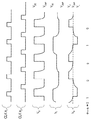
図1Aに示す基本的な機能は、どのような方法で動作させてもよい。図1Bに示す1つの動作方法では、符号φ1およびφ2で示す重複しない2つの制御信号が、電荷移動プロセスを引き起こす。これにより、可測キャパシタンス102から積分キャパシタンス108に電荷が移動することが可能にされ、積分キャパシタンス108に保持されている電荷レベルを調整するために、デルタキャパシタンス126から逆符号の電荷が移動する。この電荷の移動は、図1Bに示すVX、VIおよびVDの一連の電圧ラインに反映されている(VX、VI、VDは、キャパシタンス102,108,126をそれぞれ指している)。図に示すように、データ値114がロー(“0”)のときはVDはハイ(図1Aの“VH”)に設定され、ハイのときはロー(図1Aの“VL”)のままである。スイッチ122が積分キャパシタンス108に結合すると、デルタキャパシタンス126から適切な電荷が積分キャパシタンス108に移動し、これにより、電圧VIが適宜変化する。最初の立ち上がり時間が過ぎると、電圧VIは、通常、比較器電圧Vcmpに近づく。これは、負帰還の結果、デルタキャパシタンス126によって、積分キャパシタンス108に電荷が追加されるか、あるいはここから電荷が減らされるからである。
The basic functions shown in FIG. 1A may be operated by any method. In one method of operation shown in FIG. 1B, two non-overlapping control signals denoted by φ 1 and φ 2 cause the charge transfer process. This allows charge to move from the
可測キャパシタンスの値の範囲は、VX、VL、VH、デルタキャパシタンス126の値、1測定サイクルにデルタキャパシタンス126がフィードバックされる回数(N)、および1測定サイクルに可測キャパシタンス102が受動回路網109と再分配される回数(M)によって決定される。測定サイクルは、受動回路網109の電荷が所定のしきい値と比較される間隔である。一次の場合、決定される可測キャパシタンス102の値は(Vcmpへの電圧VIの制御が維持されると仮定した場合)、CD(N/M)((VL−Vcmp)/(VX−Vcmp))と、CD(N/M)((VH−Vcmp)/(VX−Vcmp))の間の値となる。上記したように、多くの代替の実施形態では、図1A〜Bの特定の符号規則およびその他の特定の動作パラメータが変更されてもよい。
The measurable capacitance values range from V X , V L , V H ,
次に、図2を参照する(ただし、図1に示す構造的な特徴も引き続き参照する)。シグマデルタキャパシタンス検知を最適に実装するための例示的な方法200は、可測キャパシタンス102に電圧を印加するステップ(ステップ202)と、可測キャパシタンス102から、積分キャパシタンス108を含む受動回路網109に、電荷が移動することを可能にするステップ(ステップ204)と、次に、しきい値(ステップ206)に基づいて、受動回路網の電荷を調整するステップ(ステップ210)の広いステップを有する。正確なシグマデルタ測定を可能にするために、プロセス200のさまざまステップの各々が、適切な繰り返し回数繰り返される(ステップ214)。
Reference is now made to FIG. 2 (but with continued reference to the structural features shown in FIG. 1). An
充電ステップ202では、適宜、任意の適切な手法を使用して、可測キャパシタンス102に既知の電圧が印加される。各種の実施形態では、課電圧104(例えば、ローまたはハイのデジタル出力、電源信号など)が、適宜、コントローラの信号ピンまたはその他のスイッチ106をオンにする(activate)ことによって印加される。特定の構成において変換器100の各種スイッチを図示したが、これは単に構成の1タイプの例示に過ぎないことが理解されるべきである。また、各種の実施形態においてスイッチを「使用する」または「オンにする」という場合、この「使用する」または「オンにする」ことは、スイッチの選択的な閉動作、スイッチの選択的な開動作、あるいはほかの方法でのスイッチの作動の任意の組合せとして実装できることも理解すべきである。このため、特定の実装のレイアウトに応じて、スイッチの開閉の両方を任意に組み合わせることによって、スイッチを使用して電圧を印加することができる。更に、1つ以上のパルスにより(例えば、スイッチ106を繰り返し入れて切ることによって)、あるいはほかの方法によって、課電圧が、少なくとも1回、可測キャパシタンス102に印加されうる。
In the charging
充電後、可測キャパシタンス102は、増幅器またはその他の能動素子を必要とせずに、電荷をほぼ積分し、蓄積することが可能な受動回路網109と、電荷を再分配することが可能にされる。単純な実施形態では、受動回路網109は、単純に積分キャパシタンス108であり、これは1つのコンデンサであってよい。別の実施形態では、受動回路網109は、任意の個数の抵抗、コンデンサおよび/またはその他の受動素子を適宜有してもよく、以下に、受動回路網の例を数多く記載する。可測キャパシタンス102が、受動回路網と電荷を再分配することを可能にするために必要な動作は、電荷が移動できるだけの十分な時間休止させる(可測キャパシタンスを充電しないなど)だけである。各種の実施形態では、休止時間が比較的短くても(積分キャパシタンス108が可測キャパシタンス102と直接接続されている場合など)、多少の遅延時間が生じてもよい(例えば、可測キャパシタンス102と積分キャパシタンス108の間に1つ以上の抵抗素子が設けられている受動回路網109を、電荷が移動するためなど)。別の実施形態では、電荷移動を可能にすることには、1つ以上のスイッチ(図1のスイッチ106など)を能動的に作動させるかまたは、適宜、その他の動作をとることが含まれうる。各種の実施形態では、ステップ202および/または204が2回以上繰り返されてから、その後の動作が行われてもよい。
After charging, the
可測キャパシタンス102は、フィルタキャパシタンスに静的に接続されうるが、キャパシタンス間での電荷の再分配は、充電ステップ202の終了時(可測キャパシタンスへの電圧の印加が停止したとき)に実質的に開始するとみなすことができる点に留意すべきである。更に、再分配された電荷が無視できる程度に、キャパシタンスの電圧同士が近くなると、キャパシタンス間での電荷の再分配が実質的に終了するとみなすことができる。また、電荷の再分配は、次に電圧を印加すると、印加されている(例えば104の充電)電圧が支配的となるため、実質的に終了しうる。このため、フィルタキャパシタンスが可測キャパシタンスに常に結合されている受動的な再分配系であっても、印加電圧源の低インピーダンスによって、印加電圧がなくなるまで、可測キャパシタンスの電荷が無視できる程度で再分配される
The
可測キャパシタンス102からの電荷が受動回路網109に実質上移動すると、受動回路網109の電荷が適切に測定され(ステップ206)、電荷量が適切なしき閾値を越えていると決定されると(ステップ208)変更される(ステップ210)。電荷測定は、どのような方法で行ってもよい。各種の実施形態では、受動回路網109上の電圧は、その電荷が、マイクロコントローラまたはその他の装置の入出力(I/O)ピンから取得されたことを表している。多くのこのような実施形態では、入力ピンと関連する回路が、アナログ−ディジタル(A/D)変換を実行するか、または測定した電圧を1つ以上のスレッショルド電圧VTHと比較することもでき、ステップ206と208を効率的に実行できる。特定の閾値VTH(例えば、図1で量子化器110に供給されるVcmpが表わす基準電圧112)は実施形態によって大きく変わっても、経時により徐々に変化してもよい。単純な実施形態では、CMOSティジタル入力が、比較器(1ビット量子化器)として機能し、基準電圧は、ティジタル入力のしきい値レベルと等しくなっている。量子化器110と受動回路網の接続は、直接の接続であっても、またはマルチプレクサまたはその他の交換網を介したものであってもよい。
When the charge from the
シュミットトリガなど、入力がヒステリシスを有する場合には、測定した電圧を比較する前に、ヒステリシスが既知の状態に確実に設定されるようにし、すべての比較で閾値を同じに設定することが有用なことが多い。あるいは、ヒステリシスを既知の状態に設定して、比較ごとに閾値を確実に選択してもよい。これは、比較の前の入力を既知の値に設定して、そのヒステリシス状態を設定するだけで行うことができる。 If the input has hysteresis, such as a Schmitt trigger, it is useful to ensure that the hysteresis is set to a known state before comparing the measured voltages and to set the thresholds the same for all comparisons. There are many cases. Alternatively, the threshold may be selected reliably for each comparison by setting the hysteresis to a known state. This can be done simply by setting the input before the comparison to a known value and setting its hysteresis state.
受動回路網109の電荷が適切な閾値を超えると、上記したような従来のシグマデルタ法を使用して、可測キャパシタンス102からの再分配電荷に対向する「デルタ」電荷が、(例えば図1のデルタキャパシタンス126を介して)印加され、受動回路網109の電荷が変更される(ステップ210)。多くの実施形態では、電荷が閾値を超えなくても(ステップ211)、受動回路網109の電荷が変更されてもよい(ただし、ステップ208で印加される量とは異なる量が印加される)が、この特徴は全ての実施形態で必須というわけではない。複数の閾値が使用される場合、異なる量の電荷がフィードバックされてもよい。充電サイクルのステップの繰り返しでの異なる状態において、さまざまなキャパシタンス(可測キャパシタンス、デルタキャパシタンス、積分キャパシタンスなど)を通る電荷移動の向きが変わりうるが、ここでは、サイクルの正味の電荷移動を指している点に留意されたい。このように、可測キャパシタンス102が範囲内の場合、受動回路網109上の電荷が、受動回路網109の関連する電圧に必要な値に維持され、これは閾値(VTH)とほぼ等しい。これは、(一時的に図1を参照すると)、量子化器110の出力が、正味の負帰還系においてデルタキャパシタンス126を介してフィードバックされるために、積分キャパシタンス108両端の電圧が、制御ループのため動作中はほぼ一定となるからである。
When the charge of the
ステップ206で測定した量子化(例えばデジタル)値、および/またはそこから導出される任意の量(特定の期間内に格納される「ハイ」または「ロー」の値のカウントなど)は、量子化データとしてメモリに容易に記憶され、デジタル的にフィルタされるかあるいはほかの方法によって適宜処理されうる(ステップ212)。さまざまなフィルタを、シグマデルタ測定法と共に適宜実装することができ、これには、三角フィルタ、平均化フィルタ、およびカイゼルフィルタ等の従来のデジタル有限インパルス応答(FIR)フィルタのほか、無限インパルス応答(IIR)フィルタがある。
The quantized (eg, digital) value measured in
数多くの有用な特徴を実装するために、電圧の印加、電荷移動、電荷の変更などのステップが、個別および/または集合的に、任意の回数、繰り返されうる(ステップ214)。例えば、可測キャパシタンス102の量子化値を複数取得することによって、ノイズ効果の低減、信頼性のより高い測定値の提供などのために、測定値に対して、間引き、フィルタリング、平均化および/またはその他のティジタル処理を、制御回路内で容易に行うことができる。多くのこのような特徴について以下に記載する。
To implement a number of useful features, steps such as voltage application, charge transfer, charge modification, etc., can be repeated individually and / or collectively, any number of times (step 214). For example, by obtaining a plurality of quantized values of the
多くの実施形態の1つの利点として、従来のデジタルコントローラ(マイクロコントローラ、ティジタル信号処理装置、マイクロプロセッサ、プログラマブル論理アレイ、特定用途向け集積回路など)と共に、受動素子のみを使用して、多用途の静電容量センサを容易に実装することができるという点がある。これらの製品の多くは、米国アリゾナ州チャンドラー所在のマイクロチップ・テクノロジー(Microchip Technology)、テキサス州オースティン所在のフリースケール・セミコンダクタ(Freescale Semiconductor)、およびテキサス州ダラス所在のテキサスインスツルメンツ社(TI)などのさまざまな供給元から容易に入手可能である。ここに記載する制御回路の多くは、ここに記載するさまざまなシグマデルタ処理ルーチンの実行に使用するデータおよび命令の記憶に使用できるティジタルメモリ(例えばスタティックランダムアクセスメモリ、ダイナミックランダムアクセスメモリまたはフラッシュランダムアクセスメモリ)を備える。例えば、プロセス200は、ここに記載するように、1つ以上の制御回路によって実行されるコンピュータ実行可能な命令を使用して、容易に実装することができる。
One advantage of many embodiments is that, in conjunction with conventional digital controllers (microcontrollers, digital signal processors, microprocessors, programmable logic arrays, application specific integrated circuits, etc.) There exists a point that an electrostatic capacitance sensor can be mounted easily. Many of these products include Microchip Technology in Chandler, Arizona, Freescale Semiconductor in Austin, Texas, and Texas Instruments (TI) in Dallas, Texas. It is readily available from a variety of suppliers. Many of the control circuits described herein are digital memories that can be used to store data and instructions used to execute the various sigma delta processing routines described herein (eg, static random access memory, dynamic random access memory, or flash random Access memory). For example, the
図3〜8は、コンデンサおよび/または抵抗から構成された一体型の制御回路と単純な受動回路網を使用して実装されたシグマデルタ静電容量センサの例示的な実施形態のいくつかを示す。これらの実施形態のいずれも、無数の方法で補足したり、変更して、いくつもの代替の実施形態を生み出すことができる。 3-8 illustrate some of the exemplary embodiments of a sigma delta capacitive sensor implemented using an integrated control circuit comprised of capacitors and / or resistors and a simple passive network. . Any of these embodiments can be supplemented or modified in myriad ways to produce a number of alternative embodiments.
次に図3Aを参照すると、例示的な静電容量センサ300は、少なくとも3本の入出力信号ピン(I/O)304,306,308と、電源およびグラウンド(または適宜ほかの基準値)へのスイッチとして動作する、コントローラ102内のそれぞれ関連する回路とを有するコントローラ302を適宜有する。図3Aの例では、I/O3(ピン308)は可測キャパシタンス102に結合され、ほかの2つのピンI/O1(ピン304)とI/O2(ピン306)は積分キャパシタンス108を有する受動回路網109に結合されている。積分キャパシタンス108は、可測キャパシタンス102を介して充電され、デルタキャパシタンス126を介して放電されるか、または、この逆が行われる。積分キャパシタンス108は、通常、可測キャパシタンス102の予想値よりもはるかに大きなキャパシタンスを示すように選択され、デルタキャパシタンス126は、測定可能な最大のキャパシタンスを設定するように選択される。この例でも、信号ピンおよび受動回路網109の部品の特定の構成と同様に、特定の容量値とその関係は、特定の実施形態に従って変更されてもよい。例えば、図3Bは、図3Aに示した「並列」構成と同じように動作する3ピンの2コンデンサセンサ350の直列の構成を示す。
Referring now to FIG. 3A, an
各種の実施形態では、コントローラ302内のハードウェア、ソフトウェアおよび/またはファームウェア論理は、入出力(I/O)ピン304,306,308に供給される制御信号、およびこれらが受け取る制御信号を制御することによって、シグマデルタ測定プロセスを適切に順序付け、制御する。例示的な動作では、コントローラ302は、ピン308上の電圧を測定することによって、積分キャパシタンス108の電荷を適切にサンプリングする。別の実装では、電圧が他のノードで測定されてもよい。この電圧は図1の量子化器110の入力に相当し、多くの実施形態では、コントローラ回路302内で利用可能なデジタル入力の閾値、オンボードADCまたはシュミットトリガ入力を使用して、定量化することができる。別の実施形態では、ピン308上の電圧を適切な基準値112(図1)と比較するためのアナログ比較器回路が設けられてもよい。データ表現の規則は実施形態によって変わってもよいが、(ピン308の)積分キャパシタンス108上の電圧がしきい値よりも大きい場合が、ある論理値(“1”など)に関連付けられ、しきい値よりも小さい場合が、別の論理値(“0”など)に関連付けられうる。これらの量子化データは、後続の処理のため適宜記憶される(上のステップ212を参照)。シュミットトリガ入力など、ヒステリシスを有する入力が量子化器100として使用される場合には、ここに示した方法の状態0と状態1は、信号ピン308を既知の状態のヒステリシスとする点に留意されたい。
In various embodiments, the hardware, software and / or firmware logic within
図3Aのセンサ回路300を動作させるための例示的な方法が図3C〜Dに示される。受動回路網109の動作を制御するために、図3C〜Dの「状態1」として示すように、まず、(バッテリ、VDDなどの電源電圧、またはその他の基準電圧からの)実質的に一定の充電電圧が、実質的に一定時間、可測キャパシタンス102に印加される。また、デルタキャパシタンス126に保持されている電荷を除去するために、同じ充電電圧に信号ピン306が駆動される。次に、「状態2」に示すように、ピン306,308を、中間のハイインピーダンスまたは「開放」状態にすることによって、可測キャパシタンス102に印加された電荷が、可測キャパシタンス102に隔離されうる。この中間状態は重複のないスイッチ状態を表しているが、この手法は、明らかに別の状態を使用しなくても行うこともできる。また、ほかの中間的な高インピーダンス状態によって、別の遷移が行われてもよい。次に、状態3において、課電圧の状態と対向する論理状態電圧をピン304に印加することによって(例えば、課電圧が「ハイ」の場合は「ロー」状態を印加するか、あるいはこの逆を行うことによって)、可測キャパシタンス102から受動回路網109に電荷が再分配される。
An exemplary method for operating the
上記の手法では、回路300が定常状態に近づくと、積分キャパシタンス108上の電圧(ピン304に参照される)はほぼ一定となり、ピン308のスレッショルド電圧(関連するI/OのVTHなど)とほぼ等しいはずである。信号ピン304にローが駆動されている場合は、信号ピン308における電圧も同様に、入力ピン308の閾値に相対的に近い値である。次に、状態4においてサンプリングされる量子化器(信号ピン308)の出力は、積分キャパシタンス108の電荷を示す示度となる。サンプリングされた量子化器の出力(信号ピン308の関連する入力から)に応じて、状態5により、積分キャパシタンス108の電荷が変更される。サンプリングされた量子化器(信号ピン308)の出力が閾値よりも大きい場合、状態5Aによって、積分キャパシタンス108から電荷が除去され、そうではない場合には、電荷が除去されない(または除去される電荷が無視できる)(状態5B)。デルタ電荷が印加される(受動回路網109の積分キャパシタンス108の電荷を変更する)か、または印加が省略された後は、信号ピン308がハイインピーダンス状態にされ、その後ピン308をサンプリングするために、受動回路網109の電荷がトラップされうる(状態6)。量子化データが取得され、記憶されると、このデータが、フィルタ、間引き、またはその他の方法で適宜処理され、可測キャパシタンス102の値が決定される。量子化器(例えば信号ピン308)がヒステリシスを有する場合には、状態1によって入力がハイに設定されているため、ヒステリシスの下限の閾値によって出力が決定される。
In the above approach, as the
積分キャパシタンス108が可測キャパシタンス102を介して放電され、デルタキャパシタンス126を介して充電される別の実施形態では、量子化器の閾値を下回った場合に電荷が変更される。別の変形例では、正電荷または負電荷が、可測キャパシタンス102およびデルタキャパシタンス126を介して(though)積分キャパシタンス108と再分配されても、電荷が再分配されなくても、しきい値の測定にほかのノード(例えば図3Aのピン304)が使用されてもよい。
In another embodiment, where the integrating
図4A〜Bは、コントローラ302の2本の信号ピン304,306によってシグマデルタサンプリングを可能にする同様の実装を示す。図4Aの実装400では、受動回路網109は、可測キャパシタンス102と、信号ピン306とに接続する、分離抵抗402と直列の積分キャパシタンス108を適宜有する。また、図4Aの実装は、信号ピン304,306に接続されたデルタキャパシタンス126も有する。また、図4Aの実装(および別の実装)は、電源のノイズ除去を向上させるために、任意選択で、電源電圧と分離抵抗402の間に第2のキャパシタンス407を有していてもよい。第2のキャパシタンス407は、電源のノイズが図1Aに110として一般化して示した量子化器のしきい値に結合するのと同じ比で、電源のノイズがノード403に結合するように選択される。電源ノイズの効果を低減させるための他のトポロジも可能であり、2つの例が図9A〜Bに示される。図9Aは、1つ以上の積分キャパシタンス108に接続された、キャパシタンス407Aと並列であり、キャパシタンス407Bと直列の抵抗901を示す。図9Bは、1つ以上の積分キャパシタンス108に接続され、別の第2のキャパシタンスのない、分圧器を形成している2つの抵抗903,905を示す。図9A〜Bに示す例のように、第2のキャパシタンス407A,Bを使用したり、それに代わるものを利用することは、積分キャパシタンス108を複数有するシステムでは特に有用である。第2のキャパシタンス407A,B、およびそれに代わるものに対して1つの積分キャパシタンス108しか図示していないが、複数の積分キャパシタンスが同じノードを共有してもよい。図4Bの400の「直列」の変形例は、可測キャパシタンス102を積分キャパシタンス108から分離している分離抵抗402を有する受動回路網109を示している。
4A-B show a similar implementation that enables sigma delta sampling with two
これらの実施形態のいずれにおいても、可測キャパシタンス102は、積分キャパシタンス108と分離抵抗402によって生成されるRC時定数によって実質的にブロックされるのに十分短い充電パルスで充電される。また、充電パルスは、好ましくは、可測キャパシタンスと分離抵抗のRC時定数よりも短い。これによって、可測キャパシタンス102の充電と、積分キャパシタンス108上の電圧の測定の両方を、同じピンを使用して行うことができるようになる。いずれの実施形態においても、信号ピン304またはピン306上で測定された電圧が、デルタキャパシタンス126からの電荷が積分キャパシタンス108と再分配されるかどうかを決定しうる。図4Aの実施形態では、信号ピン306は、可測キャパシタンス102に充電電圧を印加するために使用され、信号ピン304は、デルタキャパシタンス126に充電電圧を印加するために使用される。図4Bの実施形態は異なっており、信号ピン306は、デルタキャパシタンス126に課電圧を印加して、積分キャパシタンス108の電荷を変更するために使用され、信号ピン304は、可測キャパシタンス102に充電電圧を印加するために使用される。図4Bの実施形態では、デルタキャパシタンス126からの再分配を行うことなく、可測キャパシタンス102から積分キャパシタンス108に電荷を複数回再分配するか、または可測キャパシタンス102から電荷を再分配することなく、デルタキャパシタンス126から積分キャパシタンス108に電荷を複数回再分配することが簡単である点に留意されたい。
In any of these embodiments,
これらの実装の多くでは、充電電圧の前に、先に「電流取消」電圧が印加されてもよい。「電流取消」電圧のタイミングは、状態0で分離抵抗402を介して除去される「寄生」電荷の量が、状態1で分離抵抗402を介して積分キャパシタンス108に追加される「寄生」電荷とほぼ等しくなり、可測キャパシタンス102が、受動回路網109との再分配の前に適切な充電電圧となるように制御される。これにより、可測キャパシタンスの充電タイミングの要件を変えることなく、受動回路網109の低インピーダンスと(分離抵抗402の低い値など)、全体としての受動回路網109の早い時定数が可能となる。
In many of these implementations, a “current cancel” voltage may be applied prior to the charging voltage. The timing of the “current cancel” voltage is such that the amount of “parasitic” charge removed through
可測キャパシタンス102は、分離抵抗402を介して積分キャパシタンス108と電荷を再分配する。抵抗が生み出すRC時間遅延のため、この実施形態は、図4を参照して記載した3ピンの実施形態よりも、電荷の再分配のために使う時間が長くなることがある。しかし、一部の実施形態では、センサの実装に使用するスイッチ/論理回路ピンの数を低減させることによって、共通のチップに追加の検知チャネルを設け、これにより効率向上を図ることが可能となる。
The
図4A〜Bに示す例示的な回路は、任意の数の追加の機能を実装するために、さまざまに変更することができる。例えば、コントローラ302のタイミングの精度が比較的高い実施形態では、デルタキャパシタンス126の代りに、従来の抵抗を用い、単に所定時間、ピン304(図4Bではピン306)をオンにすることによって、積分キャパシタンス108に「デルタ」電荷を印加してもよい。更に、信号ピン306のADC機能に存在するヒステリシスの影響を低減させるために、分離抵抗402は有用でありうる。
The example circuits shown in FIGS. 4A-B can be variously modified to implement any number of additional functions. For example, in an embodiment where the
図4Aに示す回路400を動作させるための1つの手法が、図4Cの状態図と、図4Dのタイミング図に示される。これらの図を参照すると、可測キャパシタンス102のレベルを検出するプロセスは、任意選択で、信号ピン306を既知の(例えば論理値ロー)状態にして始まる(状態0)。分離抵抗402が、積分キャパシタンス108と共にRC時定数を生成するため、各リードサイクルの前に、ピン306(図4Bではピン304)が、積分キャパシタンス108に蓄積されている電荷量に大きく影響することなく、短時間、既知の状態(例えばローの論理状態)とされる。積分キャパシタンス108の電荷をサンプリングする前に、たとえ短時間であっても、信号ピン306を既知の状態にすることによって、ピン306のヒステリシスの量がわかり、コントローラ302内で補償することができる。状態0と状態1のタイミングが制御されれば、これらの状態間に抵抗402を通って積分キャパシタンス108に流れる寄生電荷を最小化することができる。
One technique for operating the
次に、状態1に示すように、ピン304,306を既知の(ハイの)論理状態にすることによって、可測キャパシタンス102が充電され、デルタキャパシタンス126が除去される。その後、ピン306を高インピーダンス状態にすることによって、可測キャパシタンスに電荷がトラップされ(状態2)、続いて、分離抵抗402を介して可測キャパシタンス102から積分キャパシタンス108に電荷が再分配する(例えば充電または放電)ために十分な遅延時間が設けられる。電荷が可測キャパシタンス102から再分配されると、(前の状態6において)積分キャパシタンス108上で測定された電圧に基づいて、デルタキャパシタンス126からの「デルタ」電荷が印加されるか、印加が行われない。ここに示した例では、「デルタ」電荷の印加の有無を決定する際に使用された電圧レベルは、前のシグマデルタプロセスの繰返しで取得していた。別の実施形態では、「デルタ電荷」の印加と再分配の直前、あるいは検出プロセスのほかの時点で電圧が測定されてもよい(状態3など)。
The
図5に示すセンサ500を使用すれば、信号ピンの使用本数を更に削減することができる。この場合、可測キャパシタンス102と、積分キャパシタンス108および分離抵抗402から構成される受動回路網109とが、コントローラ302の1つの信号ピン306に接続している。図4Aの実装と同様に、図5Aの実装も、電源のノイズ除去を向上させるために、電源電圧と分離抵抗402間に第2のキャパシタンス407を任意選択で有するか、あるいは図9A〜Bに示す回路の1つなどの代りのものを有しうる。この実施形態においても、積分キャパシタンス108に蓄積された電荷への悪影響を低減させるかなくすために、可測キャパシタンス102は、分離抵抗402と積分キャパシタンス108によって生成されるRC時定数よりも短い電圧パルスによって充電される。前述のように、可測キャパシタンス102が分離抵抗402を介して放電し、既知の時間、分離抵抗402に電流を流すために、ピン306に放電電圧をかけることによって、「デルタ」電荷が積分キャパシタンス108に印加される。センサ500が上記のように分離抵抗402を有するため、ピン306のヒステリシスの補償は、サンプリング前にピンを既知の状態にすることより、同様に行うことができる。状態0と状態1の間に抵抗402を流れる寄生電流は、課電圧のタイミングの制御と「電流取消」電圧によって最小化することができる。
If the
このような回路を動作させるための例示的な方法が、図5Bおよび5Cに示される。これらの図を参照すると、ピン306は、任意選択で、充電電圧の前に、「電流取消」電圧(グラウンドなど)を供給するように設定され、除去される寄生電荷の量が、充電パルスによって追加される寄生電荷の量にほぼ等しくなるように、「電流取消」電圧の長さが選択される。その後、(ネットワークのRC時定数と比較して)比較的持続時間の短い電圧パルスを印加することによって、可測キャパシタンス102が充電され(状態1)、次に、分離抵抗402を介して積分キャパシタンス108と電荷を再分配することが可能にされうる(状態2)。電荷の再分配に十分な時間が経過したら、ピン306上の電圧をサンプリングすることで電荷が測定され(状態3)、測定した電圧に基づいて、適宜「デルタ」電荷が積分キャパシタンス108に印加されうる(印加されないこともある)(状態4)。ここでも、この実施形態では、積分キャパシタンス108の電荷の所望の変化を得るために、信号ピン306に適切な電圧を適切な時間印加することによって、「デルタ」電荷が単に印加される。
An exemplary method for operating such a circuit is shown in FIGS. 5B and 5C. Referring to these figures,
上に記載した一般的な構造、概念および手法は、さまざまに変更したり補ったりすることができ、異なるが似ている多くの実施形態において利用することができる。例えば、図6A〜Bは、上記の手法を使用して、複数のチャネルのキャパシタンスを検知することができる回路の2つの例を示している。次に図6Aを参照すると、例示的な2チャネル位置センサ600が示されており、これは、それぞれが上の説明の可測キャパシタンス102に相当する2つの感知電極602,604を有する。指、スタイラスまたはその他の物体が電極602,604のいずれかに接近すると、そのノードのキャパシタンスが変化し、その変化は、物体の存在と相関させることができる。換言すると、電極602,604のいずれかの近くに物体が存在しているか、これらに物体が接触していることを、その電極チャネルのキャパシタンスを測定することによって決定することができる。
The general structure, concepts, and techniques described above can be modified or supplemented in various ways and utilized in many different but similar embodiments. For example, FIGS. 6A-B show two examples of circuits that can sense the capacitance of multiple channels using the techniques described above. Referring now to FIG. 6A, an exemplary two
一般に、センサ600の各チャネル(およびB)で使用される検知方式は、上の図4Aに関して記載した2ピン式センサ400に匹敵する。当然、代替の実施形態では、ここで記載または言及したほかの任意の方法が使用されてもよい。図6Aの例示的な実施形態では、コントローラ302のピン306,310をそれぞれ介して、電極602,604に電圧が印加される。各電極602,604は、(それぞれ)分離抵抗402A,402Bによって、積分キャパシタンス108A,108Bと電荷を再分配することが可能にされる。次に、各積分キャパシタンス108A〜Bに保持されている電荷レベルが、信号ピン306,310において電圧を量子化することによってサンプリングされ、その際、印加されている信号ピン304,308を操作して、関連する積分キャパシタンスの電荷を変えることにより、デルタキャパシタンス126A〜Bからの必要な「デルタ」電荷が印加される。
In general, the sensing scheme used in each channel (and B) of
更に、検知チャネルの対称性により、部品が共有される実施形態が可能となる。例えば、必要な積分キャパシタンス、デルタキャパシタンスおよび/または抵抗を、複数のセンサチャネル間で共有することができる。1つの例示的な実施形態が図6Bに示されている。このように共有部品を使用することによって、システム全体のコストおよびサイズを大幅に低減させることができる。実際、幅広い代替の実施形態にわたって、コントローラ302の信号ピンおよび/または受動回路網109内の任意の別個の部品を共有するために、さまざまな手法を実装することができる。
Furthermore, the symmetry of the sensing channel allows for embodiments where parts are shared. For example, the required integral capacitance, delta capacitance and / or resistance can be shared between multiple sensor channels. One exemplary embodiment is shown in FIG. 6B. By using shared components in this way, the cost and size of the entire system can be greatly reduced. Indeed, various approaches can be implemented to share the signal pins of
共通のコントローラ302に複数の検知チャネルを実装することによって、多くの能率向上を実現することができる。多くの場合、可測キャパシタンス用の感知電極、およびデルタキャパシタンス用のその他の電極を、標準的なプリント回路基板(PCB)に容易に形成することができるため、製造面では、これらの素子の複製は比較的安価である。しかし、積分キャパシタンス108および分離抵抗402などの特定の部品は、個別の部品を使用するほうがよいほど、十分大きいことがある。同様に、デルタキャパシタンスの精度が重要な場合には、同様にデルタキャパシタンスが個別の部品として実装されてもよい。一部の実施形態では、1つ以上の分離抵抗402が、インクプロセスなどを使用してPCBに形成され、その際、導電性インクは、PCBプロセスで使用される代表的な材料よりも抵抗が高い。分離抵抗402の正確な値は、通常は、システムの正確さまたは性能に直接影響を及ぼすことはないため、多くの実施形態ではこれで十分である。また、可測キャパシタンス102が比較的小さい場合には、積分キャパシタンス108も、ポリイミドのフレキシブルプリント回路等を用いるなどによって、PCBに製造してもよい。この結果、上記したさまざまな機能の多くは、従来の製造技術および構造を使用して、容易に実装することができる。更に、何らかの時分割多重化、周波数分割多重化、符号多重化またはその他の多重化法によって、必要な信号ピンの総数と受動回路網109内の部品点数を更に削減することができる。
By implementing a plurality of detection channels in the
感知電極602,604を、幾通りもの従来のパターンに配置することにより、多くのさまざまなタイプのセンサレイアウト(一次元、二次元、またはそれ以上の次元のタッチパッドアレイでみられる多次元レイアウトなど)を作製することが可能となる。別の実施形態として、複数の「ボタン」型のタッチセンサをさまざまなチャネルから容易に形成することも、あるいは、他のセンサレイアウトを幾通りも作成することもできる。
By arranging the
更に、ここに記載するさまざまなシグマデルタ検知手法を、マルチチャネル積分が容易であることと組み合わせると、保護信号を非常に効率的に印加できるようになる。複数のセンサチャネル602,604を、共通のコントローラ302に接続することにより、信号チャネルの検知中に、保護電極605に保護信号を印加することが可能となる。一般化すると、センサ電極602,604のそれぞれを、望ましくない電気信号(他の電極から、および外部のセンサ600,650から意図せず受け取った他の信号など)から絶縁することが望ましい。センサ600内のチャネルのそれぞれは、共通の参照電圧と論理電圧によって容易に実装することができるため、さまざまなセンサ電極602,604でみられる代表的な電圧値は、経時平均をとればほぼ等しくなると容易に仮定することができる。それ以外は不活性の期間に、さまざまな電極に低インピーダンス源から保護信号を印加することによって、スプリアス効果を低減させることができる。実際、1つの保護信号が、同程度の感知電極電圧の振幅を有する全てのセンサ電極に対して有効なことがある。
Furthermore, the various sigma delta detection techniques described herein can be combined with the ease of multi-channel integration to provide a very efficient protection signal application. By connecting a plurality of
分圧器(または、より一般的にはインピーダンス分割器)の低インピーダンスレッグ(leg)が、高いインピーダンスレッグよりも優勢であるように、低インピーダンスの電圧源は、あるノードにおいて他の結合信号より優勢となる。つまり、電圧源の集合について、1つのテヴナン(Thevenin)インピーダンスとして近似することができ、最も低いインピーダンスが、他のすべての発生源の並列インピーダンスよりも相当低い場合、1つのテヴナン電圧が、その最も低いインピーダンス要素によって支配されると考えることができる。この例のために、基準電圧、信号ピン出力、スイッチまたはI/O出力の出力インピーダンスは、他の発生源が考慮する周波数の範囲で重要ではなくなるように、そのノードにおいて十分低いインピーダンスを有する。同様に、積分キャパシタンスの一方の近い側に接続されたノードは、積分キャパシタンスのもう一方の遠い側が低インピーダンス(例えば基準電圧など)で駆動されたときに、容量結合されたほかの発生源を支配するのに十分に高いキャパシタンス(および低いインピーダンス)を有する。すなわち、遠い方の端が低インピーダンス源で駆動されたときに、積分キャパシタンスは、近い方の端において、電圧をセットして、高インピーダンスの他の発生源からの電荷の大部分を吸収しうる。明らかに、ネットワーク内の優勢なインピーダンスは、考慮する期間(または周波数)によっても決まる。このように、長時間のスケール(再分配など)では、積分キャパシタンスと直列の抵抗は、優勢な低インピーダンス要素として積分キャパシタンスの状態を変更することはないが、短時間のスケール(充電など)では、ノードの可測キャパシタンスのインピーダンスが、その直列抵抗のため優勢になりうる。適切なノードにおいて、適切な速度でスイッチを作動させることによって、優勢な低インピーダンス要素を選択して、電荷を適切に導くことができる。 A low impedance voltage source prevails over other coupled signals at one node, such that the low impedance leg of the voltage divider (or more generally the impedance divider) predominates over the high impedance leg. It becomes. That is, a set of voltage sources can be approximated as one Thevenin impedance, and if the lowest impedance is much lower than the parallel impedance of all other sources, one Thevenin voltage is the most It can be considered to be dominated by low impedance elements. For this example, the output impedance of the reference voltage, signal pin output, switch or I / O output has a sufficiently low impedance at that node so that it is no longer important in the range of frequencies considered by other sources. Similarly, a node connected to one near side of the integral capacitance will dominate other capacitively coupled sources when the other far side of the integral capacitance is driven with a low impedance (such as a reference voltage). Have a high enough capacitance (and low impedance) to do. That is, when the far end is driven with a low impedance source, the integrating capacitance can set a voltage at the near end to absorb most of the charge from other sources of high impedance. . Obviously, the dominant impedance in the network also depends on the period (or frequency) considered. Thus, on long-term scales (such as redistribution), the resistance in series with the integral capacitance does not change the state of the integral capacitance as the dominant low-impedance element, but on short-term scales (such as charging) The impedance of the measurable capacitance of the node can dominate due to its series resistance. By activating the switch at the appropriate speed at the appropriate node, the dominant low impedance element can be selected to properly conduct the charge.
保護の手法は、任意選択であり、実施形態によって大きく変わりうるが、1つの方法として、充電期間の間、活性電極(電極602または604など)に印加している電圧とほぼ等しい保護電圧を、保護電極605に印加する方法がある。能動センサ電極から関連する積分キャパシタンス(例えば、センサ600ではキャパシタンス108Aまたは108B、センサ650ではキャパシタンス108)への電荷移動が完了する前に(図2のステップ204)、保護電極605に印加される電圧が、能動センサ電極および関連する積分キャパシタンス上の電圧とほぼ等しくなるように変更される(能動センサ電極と関連する積分キャパシタンスとは、通常、電荷の再分配が起こると、電圧が等しくなるように近づく)。図6Bに示すものなど、関連する量子化器(同じ部品の信号ピン、I/Oなど)のスレッショルド電圧を使用して、システム内の関連する積分キャパシタンス上の電圧の代わりとして、保護電圧を制御することができる。これは、帰還ループが制御されている場合は、量子化器のスレッショルド電圧が、関連する積分キャパシタンス上の電圧にほぼ等しいためである。あるいは、インピーダンス分割器の出力の感度が、量子化器の限界感度と同様に、電源に比例している(rationed to)場合、インピーダンス分割器を使用して、電源変動の感度を低減させることができる。このインピーダンス分割器の例が、図6Aの抵抗606,608によって形成される分圧器で示されている。別の実装では、保護振幅(および保護電極から移動される電荷)が、電荷移動プロセスの繰り返しごとに変更されてもよい(電荷移動プロセスは、印加ステップ、可能にするステップおよび変更ステップを有する)。この保護電圧の振幅が、感知電極と同じく電圧振幅に平均化されうる。保護振幅の変更に、保護振幅をゼロにする場合や、定数値の場合が含まれるときには、追加の部品を必要としないパルス符号変調保護手法が可能となる。保護電極電圧と検知電極電圧間のオフセットが、保護の有用性に影響を及ぼすことはないが、これは、キャパシタンスを通る電荷移動では、電圧変化のみが重要であるためである。
The protection scheme is optional and can vary greatly depending on the embodiment, but as one method, a protection voltage approximately equal to the voltage applied to the active electrode (such as
センサ600は、2つの抵抗606,608を使用するインピーダンス分割器を利用するが、これは、使用できるインピーダンス分割器のタイプの一例に過ぎないという点に留意すべきである。詳細には、代表的なインピーダンス分割器は、2つの受動インピーダンスを直列で有し、受動インピーダンスのそれぞれは、少なくとも2つのノードに接続している。これらのノードの1つは、2つのインピーダンスが結合する共通のノードである。この共通ノードは、インピーダンス分割器の出力となる。インピーダンス分割器の出力は、「非共有ノード」に印加される電圧および/または電流の時間に対する関数である。インピーダンス分割器の簡単な例として、2つのキャパシタンスまたは2つの抵抗(抵抗606,608など)を有する分圧器がある。しかし、複雑なインピーダンス分割器を使用することもできる。このような複雑なインピーダンス分割器は、マッチングされていないキャパシタンス、抵抗またはインダクタンスを直列または並列で有しうる。更に、個々のインピーダンスは、容量特性、抵抗特性および誘導特性の組合せを有しうる。
It should be noted that
保護電圧は、関連する信号ピン604(図6A)または310(図6B)に関連する機能を使用して、適宜印加されうる。図6Aの実施形態では、例えば、電源(VDD)からの分圧器が、抵抗606と608を使用して作成され、ピン602が、分圧回路の抵抗608のインとアウトを効率的に切り替えており、保護電極605に印加される2つの別個の電圧を作り出している。図6Bに示す実施形態は、同様に抵抗608とコンデンサ614を有する分割回路を示しており、(図5Aに示した回路500が、電荷を再分配するときに行うように)信号ピン310は、保護電極605に印加される保護電圧を、充電電圧に制御するか、あるいはスレッショルド電圧まで緩和させる。保護電圧を駆動しているインピーダンスは、最も保護を効率的に行うためには、保護電極への総センサ結合インピーダンスよりも低くなければならない。センサまたは基準チャネルをトラッキングする、バッファまたはオペレーショナルアンプ(オペアンプ)等の能動アナログ部品を含め、他のさまざまな保護手法を使用することもできる。図6A〜Bは、一般に、上の図4A〜Dに関して記載した実施形態に基づいているが、保護の概念は、幅広い範囲の静電容量センサに適用することができる。しかし、保護は任意選択の機能であり、すべての実施形態にあるというわけでない。
The protection voltage may be applied as appropriate using functions associated with the associated signal pin 604 (FIG. 6A) or 310 (FIG. 6B). In the embodiment of FIG. 6A, for example, a voltage divider from the power supply (V DD ) is created using
多くの代替の検知方式は、複数の検知チャネル間での個別の部品および/またはコントローラ102の論理ピンの共有を利用する。例えば、図6Bに示すセンサ650は簡単な方法を示しており、これにより、デルタキャパシタンス126と積分キャパシタンス108が、2つの感知電極602,604間で共有される。同様に、図7Aに示すセンサ700は簡単な方法を示しており、これにより、デルタキャパシタンス126を印加するための信号ピン308を、2つの検知チャネル(可測キャパシタンス102A〜Bによって表す)間で共有することができる。この実施形態では、センサ700は、図3Bに関連して上記したセンサ350と同様の方法で動作するが、共通の信号ピン308を介して供給されるデルタキャパシタンス126A〜Bの側に電荷がフィードバックされる。一般に、この実施形態は、特定の積分キャパシタンス(108Aまたは108Bなど)が、対応するデルタキャパシタンス(126A,126B)の遷移に左右されるかどうかを決定するために位相を変える。詳細には、積分キャパシタンスのそれぞれが、その積分キャパシタンスのいずれの側が低インピーダンスで駆動されているかに基づいて、可測キャパシタンスまたはデルタキャパシタンスからの電荷を再分配するか、電荷を移動ブロックするかを、選択的に行いうる。このため、各デルタキャパシタンスは、可測キャパシタンスに影響を及ぼさずに遷移することが可能となり、信号ピン308を複数のセンサと共有することができ、ピン本数が低減される。トランスキャパシタンス型システムでは、駆動される感知電極(図8Aの802など)が、複数のセンサと共有されうる。これらの概念は、更に部品を改良するか、複数の可測キャパシタンス102間での信号ピンの再利用を改善するために、いくつもの追加の検知チャネルにも同様に適用することができる。
Many alternative sensing schemes utilize sharing of individual components and / or
図7Bは、センサ700の例示的な状態シーケンスを示す状態図750を含む。図7Aと図7Bを共に参照すると、第1の状態1は、ピン304,312を0に設定することによって可測キャパシタンスを放電し、ピン306,310に関連するI/Oピンを使用して、積分キャパシタンスにおいて電圧を測定(量子化)する。図示した例では、ピン304,306の状態図の遷移は、状態1の間にピン306における電圧がハイであると測定された(量子化データ1)ことを示し、ピン310,312の状態図の遷移は、状態1の間に310がローであると測定された(量子化データ0)ことを示す。これらの異なる状態遷移によって、それぞれの測定に応じて、状態5〜8の異なるデルタ電荷移動が得られる。状態8でのピン304,312の以前の測定と以前の状態に応じて、ハイからローのインピーダンスへの遷移が状態1で起こりえた点にも留意されたい。このような遷移によるピン306,310の電圧振幅によって、デルタキャパシタンス126A〜Bのほかに、寄生容量からそれぞれの積分キャパシタンス108A〜Bに一部の電荷が再分配される。これによって、可測キャパシタンスの決定においてオフセットが生じることがあるが、オフセットが小さく一定であれば除去することができ、ダイナミックレンジへの影響が最小限に留まる。
FIG. 7B includes a state diagram 750 illustrating an exemplary state sequence for
第2の状態2は、中程度のハイインピーダンス状態を含む。この状態では、信号ピン304,306,310,312が、すべて一時的に高インピーダンス状態に保持され、ピン308がデルタキャパシタンス126A〜Bをローに駆動する。この結果、各種コンデンサを切り離す中間状態になり、これらのコンデンサに電荷が一時的にトラップされる。これにより、意図せずコンデンサに望まない電荷を課しかねない信号の重複が発生しないことが確実となる。
The
第3の状態3は、デルタキャパシタンスに結合された積分キャパシタンスの電極108A,108Bをハイの論理電圧にする。これにより、計測可能なキャパシタンス102A〜B上の電圧が変わり、それぞれの積分キャパシタンス108A〜Bと電荷が再分配される。同時に、信号ピン306,308を低インピーダンスで駆動することによって、デルタキャパシタンス126A〜Bを介して結合される電荷移動がブロックされる。
The
第4の状態4では、デルタキャパシタンス126A,126Bは、これらのコンデンサの両端が、ピン306,308,310によって同じハイの論理電圧に設定されるため、その電荷を消去する。
In the
第5の状態5は、ピン306をハイインピーダンス状態にし、これにより、積分キャパシタンス108Aに電荷が保持される。これは、可測キャパシタンス102Aについて、以下の状態5で遷移する前の、信号ピン304の中程度のハイインピーダンス状態であり、積分キャパシタンス108Aに意図せずに電荷がセットされるのを防ぐ。ピン306における電圧の、量子化データの測定が1である積分キャパシタンス108Aに結合しているI/Oのみが、切り離された点に留意されたい。ピン310における電圧の、量子化データの測定が0であった積分キャパシタンス108Bに結合しているピン310は、ハイの論理電圧に保持されているが、これは、この積分キャパシタンスが、デルタキャパシタンス126Bによる電荷の変化を必要としなかったからである。
The
第6の状態6は、その後のステップ7において、デルタ電荷が、デルタキャパシタンス126Aを介して積分キャパシタンス108Aに移動できるように、信号ピン304をローの論理レベルに駆動する。ピン310は、ハイの論理レベルに保持されており、126Bと108B間でのこのデルタキャパシタンスの電荷移動がブロックされる点に留意されたい。既に説明したその後のステップ1においてではなく、このステップにおいて、ピン304のこのローの論理レベルの遷移によっても、寄生容量およびデルタキャパシタンスからの電荷の再分配が起こる点にも留意されたい。
The
第7の状態7は、ピン308上の電圧を遷移させて、積分キャパシタンス108Aからデルタキャパシタンス126Aを介して電荷を除去させるが、積分キャパシタンス108Bの電荷は実質的に影響を受けない。
最後の状態8は、ステップ7での電荷の変化を必要としなかった積分キャパシタンス(108Bなど)に対する第2の中程度のハイインピーダンス状態を有し、これらを、その後の工程での再分配に向けて準備させる。この場合も、各種のコンデンサを切り離して、そのコンデンサに一時的に電荷をトラップさせる。
The final state 8 has a second moderate high impedance state for the integral capacitance (such as 108B) that did not require a change in charge in
最後の状態8が完了すると、方法はステップ1に戻り、状態1〜8が再び実行される。このシーケンスによって、ピン306,308における積分キャパシタンス108A〜B上の電圧の測定から得た結果と、それぞれの可測キャパシタンス102Aを決定するのに適した量子化データ(例えば0または1)が得られる点に留意すべきである。可測キャパシタンス102Aとピン304,306のほか、可測キャパシタンス102Bとピン310,312のためのステップのシーケンスは、例示的なステップ1において、ピン306,310上の電圧の特定の測定(および量子化)のみを例示したものであり、測定サイクルの繰り返しにおけるその測定に応じて、いずれかの状態のシーケンスが、いずれかの可測キャパシタンスおよび積分キャパシタンスで行われてもよい。通常は、可測キャパシタンスの測定では、両方の状態シーケンスが関連するピンで行われ、両方のタイプの得られた量子化データ(例えば0および1)が、可測キャパシタンスを決定するために使用される結果の一部となりうる。
When the last state 8 is complete, the method returns to step 1 and states 1-8 are executed again. This sequence provides the results obtained from measuring the voltages on the integrating
この実施形態は、いくつかの利点を図っている点に留意すべきである。例えば、共通のノード(すなわちピン308)が常に駆動されているため、寄生容量の影響が大幅に低減される。第2に、センサ700は、並列サンプリングが可能なため(すなわち、複数のI/Oを同時に量子化する)ため、I/O状態をとらせ、複数のキャパシタンスをサンプリングするために必要なサイクル数を低減しうる。最後に、多くの可測キャパシタンスが検出された場合に、I/Oを大幅に削減できる。また、この実施形態は、積分キャパシタンスの電荷の測定中に、可測キャパシタンス(すなわちピン304,312)に結合されたノードを接地することによって、可測キャパシタンスによって結合される外部雑音、またはピン304,312に結合された他の関連する寄生容量に対する感度を低減させることができる。
It should be noted that this embodiment offers several advantages. For example, since the common node (ie, pin 308) is always driven, the effect of parasitic capacitance is greatly reduced. Second, because the
上記の実施形態は、通常、可測キャパシタンスが局所的システムアースに対して測定される、いわゆる「絶対静電容量」センサにウェイトを置いているが、同様の概念を、ほかのタイプの静電容量センサに適用することができる。例えば、図8Aは、いわゆる「駆動キャパシタンス(driven capacitance)」または「トランスキャパシタンス型」センサと共に動作するように設計されたセンサ800の別の実施形態を示す。センサ800は、積分キャパシタンス108がデルタキャパシタンス126および可測キャパシタンス102と直列であるため、「直列」センサである。図8Aに示す実施形態では、可測キャパシタンス102は2つの別個の電極802,804によって形成され、このそれぞれは、コントローラ302の信号ピン304,306を使用して、所定の電圧に駆動される。「駆動」電極802に波形が印加されると、電極802,804間と、積分キャパシタンス108を含む受動回路網109に移動する電荷を検知するために、上記のシグマデルタ検知手法を使用して電極802と804間の容量結合が検出されうる。この結果、「駆動」電極と「検知」電極間の容量結合の変化を利用するセンサは、大きな変更を伴わずに、上記の概念を容易に実装することができる。前述したように、トランスキャパシタンス型の可測キャパシタンスは、任意の数のほかの導体および/または誘電体の影響を受けて、電極802,804の近くにある構成要素と複雑な総実効キャパシタンスを形成しうる。更に、デルタキャパシタンスに関して記載し、状態図750に示したものと同様の、充電サイクルの繰り返しの間に再分配ステップの位相シフトを実施して、トランスキャパシタンス型センサの「駆動」電極との電荷の再分配をブロックするか、またはこれを可能にすることもできる。
While the above embodiments typically place weights on so-called “absolute capacitance” sensors, where measurable capacitance is measured relative to the local system ground, a similar concept applies to other types of electrostatic capacitance. It can be applied to a capacitive sensor. For example, FIG. 8A shows another embodiment of a
図8Bは、センサ800の例示的な状態シーケンスを示す状態図825を含む。図8Aと図8Bを共に参照すると、第1の状態1において、信号ピン310のI/O4の状態を変更することによって、デルタキャパシタンス126(Cd)を介して、デルタ電荷が、積分キャパシタンス108に追加されうる。状態1において、310の論理状態がこのようにローからハイの論理レベルに変化するか(あるいはローのまま保持されるか)は、前の状態7における、ピン308における積分キャパシタンス108上の電圧の以前に行った量子化の結果により、F(VCI)の関数として決まる。一例として、関数F(VCI)は、前のサイクルで、積分キャパシタンス108における電圧が、信号ピン308のI/O3のスレッショルド電圧VTHよりも高かった場合(すなわち、積分キャパシタンスの電荷がローであり、電圧降下が望ましいよりも小さかった場合)には、ピン310がローに保持される。逆に、積分キャパシタンス108における電圧が、スレッショルド電圧よりも低かった場合(すなわち、積分キャパシタンスの電荷がハイであり、電圧降下が望ましいよりも大きかった場合)には、デルタキャパシタンス126を介して積分キャパシタンス108から電荷を除去することによって、ピン310がハイに駆動され、308における電圧を上昇させる。電荷移動プロセスのそれぞれの繰り返しにおいて、I/O1がローからハイに遷移して、積分キャパシタンスに電荷を追加すると、可測キャパシタンスCx102を介しても電荷が電極802,804間で移動する。シグマデルタシステムの制御下で、可測キャパシタンス102を介して電荷を追加し、デルタキャパシタンス126を介して電荷を除去することによって、積分キャパシタンス108の電荷が、負帰還制御によりほぼ一定に保たれる。
FIG. 8B includes a state diagram 825 that illustrates an exemplary state sequence of the
このため、状態1は、ピン308の積分キャパシタンスのI/O3における以前の電圧測定に基づいてデルタキャパシタンス126を使用して、積分キャパシタンス108から電荷を除去する(すなわち1a)か、除去を行わない(すなわち1b)。この測定は、代替の実施形態でさまざまな方法で実行する実施することができ、例えば、積分キャパシタンス上の電圧の測定に、ピン306が使用されうる。
Thus,
状態2は、積分キャパシタンス108の両端(すなわち信号ピン306,308)が中程度のハイインピーダンス状態である。これにより、信号ピンの出力のタイミングの誤りによって、積分キャパシタンス108の電荷が変わらないように、積分キャパシタンス108に積分電荷がトラップされる。ピン304はローに保持され、ピン310は以前の状態に保持される。
状態3では、信号ピン308がローの論理状態(グラウンドなど)に設定される。ピン308上の電圧は、前の状態7で測定されており、信号ピン308およびI/O3に関連する入力のしきい値に近い値となっているはずである。308をローの論理状態にし、積分キャパシタンス108の一方の側で電圧を変えることによって、感知電極804における電圧も変わり、積分キャパシタンス108は、可測キャパシタンス102のほか、信号ピン306およびセンサ804においてこのノードに結合されたほかの寄生容量と電荷を再分配する。この例示的な場合には、可測キャパシタンス102と再分配される電荷は、次の工程でピン304のI/O1をハイにすることによって移動する電荷と向きが同じであるが、すべての実装でこのようになっている必要はない。804の電圧変化によって、寄生容量から積分キャパシタンス108に再分配される電荷は、本明細書に記載したほかの「絶対静電容量」センサと同様に生じるが、この例ではトランスキャパシタンス型センサとして機能する。この寄生電荷は積分キャパシタンス108に再分配され、この例では積分キャパシタンス108に電荷を追加し、ピン308での積分キャパシタンス108上の測定電圧を低減させる傾向がある。
In
第4の状態4では、ピン304のI/O1が論理値ローからハイの論理電圧に変化すると、電荷が、電極804から積分キャパシタンス108に再分配され、デルタキャパシタンス126の電荷が除去される。詳細には、この状態では、ピン304がハイにされ、ピン310がローとなる。これにより、可測キャパシタンス102(Cx)を介して、電極804から積分キャパシタンス108に電荷が再分配されることが可能にされる。同時に、信号ピン310,308におけるデルタキャパシタンス126の両端の電圧がローにされる。ピン308のノードが低インピーダンスであるため、このステップでは、デルタキャパシタンス126を介して積分キャパシタンス108に電荷が移動されることはない。
In the
第5の状態5は、別のハイインピーダンス状態であり、積分キャパシタンス108の両端が切り離される。
The
第6の状態6は、可測キャパシタンス(Cx)102の感知電極804をハイの論理電圧にし、感知電極804を介して結合される電荷の再分配をブロックし、デルタキャパシタンス126との再分配を可能にする。I/O2の信号ピン306を低インピーダンスにすることで、積分キャパシタンス108が、以下の測定ステップの間にその電極に結合されるノイズから遮蔽される。また、積分キャパシタンス108を介し、信号ピン308およびデルタキャパシタンス126に結合されたノードと電荷の再分配が可能にされる。しかし、電極804をハイの論理電圧で駆動すると、308の信号ピンノードにおける電圧も変わる。この場合も、ピン308の任意の寄生容量を介して、積分キャパシタンス108と電荷が再分配される。この例では、信号ピン310が低インピーダンスにされるため、電荷がデルタキャパシタンス126とも再分配されるが、別の実施形態ではこのようである必要はない。状態3の可測キャパシタンスの再分配とは異なり、この寄生電荷は、積分キャパシタンスの電荷を変更するために、状態1において信号ピン310の電圧が変更されたときに、デルタキャパシタンス126を介して移動した電荷と逆向きである点に留意されたい。電圧変化および寄生容量とデルタキャパシタンスの大きさに比例して一部の電荷が再分配され、積分キャパシタンス108上の電圧を上昇させ、ピン308における測定電圧を低減させる傾向がある。ピン310がハイインピーダンス状態にされた場合は、大幅に(寄生容量のみまで)低減することができた。306をハイに駆動することで発生する308の電圧遷移が、ステップ4において電荷を減らすために使用された310の電圧遷移よりも小さい限り、トランスキャパシタンス型シグマデルタプロセスで、デルタキャパシタンス126によって正味の電荷を減らすことができる。
The
第7の状態7は、積分キャパシタンス108上の電圧を測定する。ピン308がハイインピーダンス状態のときは、信号ピン306によって感知電極に駆動された電圧に対する積分キャパシタンス108上の電圧(蓄積された電荷による)を、ピン308で測定することができる。この測定では、量子化した結果を提供するために、積分キャパシタンス108における電圧がスレッショルド電圧VTHと比較されうる。次に、得られた積分キャパシタンス108上の電圧の測定結果(すなわち、スレッショルド電圧VTHより高いかどうか)が、サイクルの次の繰り返しにおいて、状態1〜3でF(VCI)において使用され、積分キャパシタンスの電荷がデルタキャパシタンス126によってどのように変更されるかが決定される。
The
このため、状態1〜7を繰り返し実行することで積分キャパシタンス108の電荷のシグマデルタ閉ループ制御が得られ、量子化した結果をフィルタした測定を使用して、電極802,804間のトランスキャパシタンスを測定することができる。測定したこのトランスキャパシタンスは、センサに対する物体の近接度検知や、ほかの任意の目的にも更に使用することができる。
Thus, repeated execution of states 1-7 provides a sigma-delta closed-loop control of the charge on the
ステップ3と6における駆動ノードと対向する積分キャパシタンス108の再分配ノードでの電圧変化によって、寄生容量による望まない電荷移動が生じ、可測キャパシタンス102またはデルタキャパシタンス126を介して、意図した向きとは逆の電荷の再分配が生じることがあるという点に留意されたい。これは、トランスキャパシタンス型センサの「絶対静電容量」動作である。電極802を駆動する信号ピン304およびデルタキャパシタンス126を駆動する信号ピン310によって使用される電圧振幅に対してこの電圧変化が小さいほど、寄生容量の影響が小さくなり、トランスキャパシタンス型シグマデルタ測定システムの機能がより理想的となる。
The voltage change at the redistribution node of the integrating
次に図8C,8Dを参照すると、トランスキャパシタンス型センサ850の第2の実施形態が示される。可測キャパシタンス102が、積分キャパシタンス108との接続においてデルタキャパシタンス126と並列にあるという点で、トランスキャパシタンス型センサ850は並列センサである。また、この実施形態では、スレッショルド電圧VTHに近い電圧VGが、抵抗812,814を有する分圧器で発生される。上記の実施形態と同様に、可測キャパシタンス102は2つの別個の電極802,804によって形成され、このそれぞれは、コントローラ302の信号ピン304,306を使用して、所定の電圧に駆動される。電極802に波形が印加されると、電極802,804間と、積分キャパシタンス108を含む受動回路網109に移動する電荷を検知するために、シグマデルタ検知手法を使用して電極802と804間の容量結合(可測キャパシタンス102によって示される)が検出されうる。
8C and 8D, a second embodiment of a
図8Dは、センサ850の例示的な状態シーケンスを示す状態図875を含む。図8Cと図8Dを共に参照すると、第1の状態1は、中程度のハイインピーダンス状態を含む。この状態では、信号ピン306,308A,308Bが、すべて高インピーダンス状態に保持され、ピン304がローの論理電圧に、ピン310がハイの論理電圧にされる。この結果、さまざまなコンデンサを切り離す中間状態になり、これらのコンデンサに電荷が一時的にトラップされる。これにより、意図せずコンデンサに望まない電荷を課しかねない信号の重複が発生しないことが保障される。
FIG. 8D includes a state diagram 875 illustrating an exemplary state sequence for
第2の状態2では、ノード851における積分キャパシタンス108上の電圧が、測定I/O(IO3など)のスレッショルド電圧VTHと実質的に等しい値に実装された発生電圧VGに設定される。詳細には、ピン308Aはハイの論理電圧(VDDなど)を供給し、ピン308Bはローの論理電圧(GNDなど)を供給し、抵抗812,814は、ノード851で電圧VGを発生させる分圧器となる。1つの例示的な実施形態では、抵抗812と814は実質的に等しく、このため、発生電圧はほぼ1/2VDDであり、これはCMOSの入力しきい値と同等である。受動素子およびスイッチ(I/OまたはDACなど)を使用して発生電圧を印加するための方法は数多く存在し、これは一例に過ぎない。デジタル入力のスレッショルド電圧は、ハイの入力からローを区別する電圧である。当然、これは一例に過ぎず、別の実施形態では、ほかの値を使用することが望ましくてもよい。例えば、I/Oがシュミットトリガ入力を利用している場合、Vdd/3の電圧が、論理値ハイに設定されたI/O3の入力しきい値に近い値となる。一部の実施形態では、分圧器が用いられないという点にも留意すべきである。その代わりに、一部の実施形態では、コントローラ302が、VTHに近い適切な電圧VGを発生させる能力を本質的に備えている。
In the
ノード851を、スレッショルド電圧VTHに近い発生電圧Vgで駆動することにより、ステップ2〜3の電極804の電圧振幅を低減できるという点にも留意すべきである。これは、シグマデルタ帰還ループが、積分キャパシタンス108の電荷を制御し、信号ピン306がノード804を駆動するときに(ステップ5,6,7)、ノード851上の電圧をスレッショルド電圧に近い値に保ち、ノード851に結合された入力(308Aなど)を測定することができるためである。804および851の電圧を一定に保つことにより、寄生容量を固定電圧(GNDなど)にすることは、寄生容量を介して移動する電荷が最小化されないため、ほとんど影響がない。積分キャパシタンス108上の電圧の測定がピン306のI/O2によって行われた場合、ノード306を、同様の発生電圧Vgで駆動して、寄生容量の影響を最小化することができるという点に留意されたい。
It should also be noted that the voltage amplitude of the
第3の状態3では、308Aにおける積分キャパシタンス108上の電圧に関する以前の測定に応じて、デルタ電荷が積分キャパシタンス108に移動するか、電荷が電極804と積分キャパシタンス108間で再分配されるか、この両方が行われる。詳細には、ピン310が、308Aにおいて積分キャパシタンス108上で以前に測定された電圧のF(VCI)の関数として駆動される。一例として、関数F(VCI)は、積分キャパシタンス108における電圧(ノード851においてなど)が、測定サイクルの以前の繰り返しでI/O3のスレッショルド電圧VTHよりも高かった場合(すなわち、積分キャパシタンスの電荷がローであり、電圧降下が望ましいよりも小さかった場合)には、ピン310がハイの論理電圧に保持されるように選択される。逆に、積分キャパシタンス108における電圧が、スレッショルド電圧よりも低かった場合(すなわち、積分キャパシタンスの電荷がハイであり、電圧降下が望ましいよりも大きかった場合)には、ピン310が論理値ローにされ、デルタキャパシタンス126を介して積分キャパシタンス108から電荷が除去される。いずれの場合も、I/O1がローの論理電圧からハイの論理電圧に遷移して、積分キャパシタンスに電荷を追加すると、可測キャパシタンスCx102を介しても電荷が電極802,804間で移動する。シグマデルタシステムの制御下で、可測キャパシタンスを介して電荷を追加し、デルタキャパシタンスを介して電荷を除去することによって、積分キャパシタンスの電荷が、負帰還制御によりほぼ一定に保たれる。
In the
このため、状態3は、ピン308Aにおける積分キャパシタンスのI/O3の以前の電圧測定に基づいて、電極804と積分キャパシタンス108間で電荷を再分配するか、あるいは積分キャパシタンス108から電荷を除去する
Thus,
第4の状態4は、意図せずコンデンサに望まない電荷を課しかねない信号の重複が発生しないことを保障する別の中程度のハイインピーダンス状態を含む。第5の状態5は、信号ピン306のI/O2を介して、受け取り側の電極804をハイの論理電圧に再び設定する。第6の状態6は、電荷移動プロセスの次の繰り返しでの遷移に備えて、可測キャパシタンス(Cx)102およびデルタキャパシタンス(CD)126に電荷を設定する。詳細には、ピン310にハイの論理電圧が印加され、ピン306にもハイの論理電圧が印加され、デルタキャパシタンス126を放電させる。同時に、信号ピン304を介して電極802にローの論理電圧が印加されて、電極804に結合された可測キャパシタンスが再充電される。可測キャパシタンス102の電極804と、積分キャパシタンス108のデルタキャパシタンス126に結合された側とに、低インピーダンスの電圧を印加することによって、このステップの間に、デルタキャパシタンス126や可測キャパシタンス102を介して、積分キャパシタンス108に電荷が移動することはない。これにより、積分キャパシタンス108の値が、前のステップで移動した電荷を正確に表す値となり、感知電極804からのノイズによって妨害されずに測定できることが保障される。
The
第7の状態7は、積分キャパシタンス108における電圧を測定する。ピン308がハイインピーダンス状態の場合、(蓄積された電荷による)積分キャパシタンス108上の電圧(ノード851における電圧など)を、ピン308Aまたはピン308Bで測定することができる。この測定では、量子化した結果を提供するために、積分キャパシタンス108における電圧がスレッショルド電圧VTHと比較されうる。次に、積分キャパシタンス108上の電圧で得られた測定結果(すなわち、スレッショルド電圧VTHより高いかどうか)が、次のサイクルにおいて、状態3〜5でF(VCI)において使用され、積分キャパシタンスの電荷がデルタキャパシタンス126によってどのように変更されるかが決定される。
The
このため、状態1〜7を繰り返し実行することで積分キャパシタンス108の電荷のシグマデルタ閉ループ制御が得られ、量子化した結果をフィルタした測定を、電極802,804間のトランスキャパシタンスを測定するために使用することができる。測定したこのトランスキャパシタンスは、センサに対する物体の近接度検知にも使用することができる。
Thus, repeated execution of states 1-7 provides sigma-delta closed-loop control of the charge on the
前述のように、図8に示したセンサの実施形態は、絶対静電容量やグラウンドを基準としたキャパシタンスではなく、トランスキャパシタンスを測定する。これらの実施形態は、測定したキャパシタンスに対する、バックグラウンド容量または寄生容量の悪影響を低減させ、このため、指紋隆線の検知および容量接触検知などの、寄生トレース(parasitic trace)容量がかなり存在する用途において特に有用である。 As described above, the sensor embodiment shown in FIG. 8 measures transcapacitance rather than absolute capacitance or ground-based capacitance. These embodiments reduce the adverse effects of background or parasitic capacitance on the measured capacitance, so applications that have significant parasitic trace capacitance, such as fingerprint ridge detection and capacitive touch detection In particular.
例えば、ノード851の発生電圧Vgが、851に結合された信号ピン(I/Oの場合は308A/Bなど)の入力スレッショルド電圧にほぼ相当する場合には、検知電極804の電圧振幅の量を、シグマデルタ帰還制御によって比較的低レベルに保つことができる。これにより、寄生容量に対する感度をかなり低減することができる。これは、ノード851に電圧が印加される(306はフローティングである)場合と、306に電圧が印加され、ノード851が信号ピン308A/Bによって駆動されない場合の両方であり、ノード851の積分キャパシタンス108上の電圧が、定常動作中にスレッショルド電圧に比較的近い値にとどまるためである。同様に、ノード851における電圧が、308A/Bの入力しきい値の一方の電圧に駆動される(信号ピン306にほかの値を印加するのではなく)ときに得られる電圧と同様の電圧が、信号ピン306に印加されるため、電極804の電圧振幅が比較的低く保たれる。851と306間の電圧差は、積分キャパシタンス両端の電圧(およびそこに存在する電荷)によって決まり、これは、シグマデルタ負帰還ループによって制御されるこの306とノード851上の電圧は、どのような方法によっても印加することができる。各種の実施形態では、ほぼ正確なスレッショルド電圧が、論理を使用してピン308A〜Bから印加され、分圧器網の一部がオンまたはオフにされて、適切な電圧が得られる。別の実施形態では、ほぼ正確な電圧が、デジタル−アナログ変換器またはその他の何らかの方法によって印加されうる。
For example, when the voltage Vg generated at the
ここに示したさまざまな回路および手法に更に改良または変更が行われてもよい。追加の能動アナログ部品の使用の有無を問わず、上記の手法を使用して、高次のシグマデルタ変調器を実装することができる。 Further improvements or modifications may be made to the various circuits and techniques shown here. The above approach can be used to implement higher order sigma delta modulators with or without additional active analog components.
更に、さまざまな雑音源を、例えば、ノイズディザ法を用いることによって低減することができる。より詳細には、従来の一次シグマデルタ変換器は、特にノイズの「トーン」(すなわちノイズの反復パターン)の影響を受けやすいことが知られている。このトーンにより、特定の一定の入力に対して、雑音が多い出力が発生し(この結果、キャパシタンスの感度が低い(あるいは誤差の大きい)「デッドゾーン」が存在することになる)、これにより、入力条件のわずかな変化に対する反応が鈍くなる。トーンは、高度な(すなわち高次の)シグマデルタ法を用いるか、あるいはシグマデルタ変換器に低出力のノイズを少量注入することによって、防ぐことができる。ノイズを注入するための1つの方法に、ADC基準電圧(図1の電圧112など)にノイズディザを適用する方法がある。このディザは、任意の種類のソフトウェアまたはその他の論理回路で生成されて、反応を向上させるために、各検知チャネルに同時に適用されうる。 Furthermore, various noise sources can be reduced, for example, by using a noise dither method. More specifically, it is known that conventional first order sigma-delta converters are particularly susceptible to noise “tones” (ie, noise repetitive patterns). This tone produces a noisy output for a given constant input (which results in a “dead zone” where the capacitance is less sensitive (or more error prone)), Response to slight changes in input conditions is slow. Tones can be prevented by using advanced (ie higher order) sigma delta methods or by injecting a small amount of low power noise into the sigma delta converter. One method for injecting noise is to apply noise dither to the ADC reference voltage (such as voltage 112 in FIG. 1). This dither can be generated with any kind of software or other logic circuit and applied to each sensing channel simultaneously to improve the response.
上記したように、キャパシタンスを決定するための装置および方法は、特に近接センサ装置に適用可能である。次に図10を参照すると、近接センサ装置11に結合された例示的な電子システム10のブロック図が示される。電子システム10は、パーソナルコンピュータ、ポータブルコンピュータ、ワークステーション、携帯情報端末、ビデオゲームプレーヤ、通信装置(移動電話およびメッセージ通信装置など)、レコーダおよびプレーヤを含むメディア装置(テレビ、ケーブルボックス、ミュージックプレーヤおよびビデオプレーヤなど)や、ユーザからの入力を受け入れて、情報を処理可能なその他の装置のどのようなタイプのものでもよい。したがって、システム10の各種の実施形態は、どのようなタイプのプロセッサ、メモリまたはディスプレイを備えてもよい。更に、システム10の各種構成要素は、バス、ネットワークまたはその他の有線または無線の相互接続を介して通信しうる。近接センサ装置11は、インタフェースまたは接続のどのようなタイプのものを介してシステム10と接続され、このいくつかの例には、I2C、SPI、PS/2、ユニバーサルシリアルバス(USB)、ブルートゥース、RF、IRDAまたはほかのタイプの有線接続または無線接続があるが、これらに限定されない。
As noted above, the apparatus and method for determining capacitance is particularly applicable to proximity sensor devices. Referring now to FIG. 10, a block diagram of an exemplary
近接センサ装置11は、コントローラ19および検知領域18を有する。近接センサ装置11は、検知領域18内の入力14(1本以上の指、スタイラスおよび/またはその他の入力物によって供給されうる)の位置に反応し、入力14によって生ずるキャパシタンスの変化を測定することによって、入力14を検出することができる。ここで用いられる「検知領域」18とは、近接センサ装置11の、上部、周囲、上、および/またはその近くなどの任意の空間を広く含むことを意図しており、この領域では、センサが物体の位置を検出することが可能である。従来の実施形態では、検知領域18は、信号対雑音比によって入力の検出ができなくなる距離まで、センサの表面から1つ以上の方向へ空間に延びている。この距離は、ミリメートル未満、ミリメートル、センチメートルまたはそれ以上のオーダーであってよく、所望のセンサの電極寸法、センサの設計および/またはセンサ性能(精度または分解能など)によって大きく変わりうる。したがって、特定の検知領域18の平坦度および曲率、大きさ、形状、および正確な位置は、実施形態によって大きく変わる。
The proximity sensor device 11 includes a
動作時に、近接センサ装置11は、検知領域18の中で1本以上の指、スタイラスおよび/またはその他の物体による影響を受ける複数の感知電極に関連する可測キャパシタンスを測定することによって、入力14の位置を適切に検出する。そして、近接センサ装置11は、コントローラ19を使用して、近接センサ装置11は、位置の電気的または電子的な指標(indicia)を、電子システム10に供給する。システム10は、上記したように、この指標を適切に処理して、ユーザからの入力を受け取り、任意の適切な目的のために適切な応答を発生させる。
In operation, proximity sensor device 11
近接センサ装置11は、任意の数の検知領域18に対応するために、別個のアレイか、あるいは静電容量センサ電極のほかの任意の構成を使用しうる。また、近接センサ装置は、提供される情報のタイプが異なってもよく、例えば、スカラーとして「一次元」位置情報(検知領域に沿ってなど)、値の組合せとしての「二次元」位置情報(例えば、水平軸/垂直軸、角度/径方向、あるいは二次元に広がるほかの任意の軸)、値の配列としての近接度の「二次元」像などがある。
Proximity sensor device 11 can use a separate array or any other configuration of capacitive sensor electrodes to accommodate any number of
コントローラ19は、時として近接センサプロセッサまたはタッチセンサコントローラと呼ばれ、一般に、上記のさまざまな手法を使用して、キャパシタンスを測定するために使用されるプロセスに指示を与える。ここでは、コントローラ19も、電子システム10と通信している。コントローラ19は、近接センサ装置11を実装するために、さまざまな追加のプロセスを実行してもよい。例えば、コントローラ19は、個々の可測キャパシタンスを選択するかまたはこれに接続したり、可測キャパシタンスの値に基づいて、位置または移動情報を計算したり、しきい値に達したときに位置または移動を報告したり、有効なタップ/ストローク/文字/ボタン/ジェスチャシーケンスを解釈および待機してから、これを電子システム10に報告するかこれをユーザに示したり、あるいは多くの異なるプロセスを行いうる。
The
本明細書においては、「コントローラ」との文言を、記載した動作を実行するために適合された1つ以上の処理要素を有するものと定義する。このため、コントローラ19は、1つ以上の集積回路、ファームウェアコードおよび/またはソフトウェアコードの全部または一部を含みうる。
As used herein, the term “controller” is defined as having one or more processing elements adapted to perform the described operations. Thus, the
再び、本願において使用される文言として、「電子システム」との文言は、近接センサ装置11と通信する装置であればどのようなものも広く指す。このため、電子システム10は、タッチセンサ装置が実装されるか、またはこれと結合される任意の1つ以上の装置を有しうる。近接センサ装置11は、任意の適切な手法を使用して、電子システム10の一部として実装されても、または電子システム10に結合されてもよい。このため、例として、電子システム10は、コンピューティング装置、メディアプレーヤ、通信装置またはその他の入力装置(別のタッチセンサ装置またはキーパッドなど)のどのようなタイプのものを有していてもよいが、これらに限定されない。場合によっては、電子システム10は、それ自体が大きなシステムの周辺装置である。例えば、電子システム10は、リモートコントロールまたはディスプレイ装置など、適切な有線または無線の手法を使用して、コンピュータまたはメディアシステムと通信するデータ入力または出力装置であってもよい(テレビ用のリモートコントロールなど)。電子システム10のさまざまな構成要素(プロセッサ、メモリなど)は、システム全体の一部として、タッチセンサ装置の一部として、またはこれらの組み合わせとして実装されうる点にも留意すべきである。更に、電子システム10は、近接センサ装置11のホストまたはスレーブであってもよい。
Again, as used herein, the term “electronic system” broadly refers to any device that communicates with the proximity sensor device 11. Thus, the
また、「近接センサ装置」との文言は、従来の近接センサ装置だけではなく、1本以上の指、ポインタ、スタイラスおよび/またはその他の物体の位置を検出することができる同等の装置の広い範囲も含むことを意図することを理解すべきである。このような装置としては、タッチスクリーン、タッチパッド、タッチタブレット、生物測定認証装置、手描きまたは文字認識装置などが挙げられるが、これらに限定されることはない。同様に、ここで用いられる「位置」または「物体位置」との文言は、絶対位置情報および比較位置情報のほか、速度、加速度などのほかのタイプの空間ドメイン情報も含むことを意図しており、これには、1つ以上の方向における移動の測定値が含まれる。位置情報のさまざまな型式には、ジェスチャ認識などの場合のように、時間履歴の成分が含まれていてもよい。したがって、近接センサ装置は、単なる物体の有無以外も適宜検出してもよく、幅広い範囲の等価物を含むことができる。 In addition, the term “proximity sensor device” refers not only to conventional proximity sensor devices, but also to a wide range of equivalent devices that can detect the position of one or more fingers, pointers, styluses and / or other objects. It should be understood that is also intended to include. Such devices include, but are not limited to, touch screens, touch pads, touch tablets, biometric authentication devices, hand drawn or character recognition devices, and the like. Similarly, the terms “position” or “object position” as used herein are intended to include other types of spatial domain information, such as velocity and acceleration, as well as absolute and comparative position information. This includes measurements of movement in one or more directions. Various types of position information may include time history components as in gesture recognition and the like. Accordingly, the proximity sensor device may appropriately detect other than simply the presence or absence of an object, and can include a wide range of equivalents.
本発明の機構は、さまざまな型式のプログラム製品として配布することができる点も理解すべきである。例えば、本発明の機構は、コンピュータ可読信号保持媒体にある近接センサプログラムとして実装および配布することができる。更に、本発明の実施形態は、配布を行うために使用される信号保持媒体の特定のタイプを問わず、等しく当てはまる。信号保持媒体の例には、メモリーカード、光学ディスクおよび磁気ディスク、ハードディスクドライブなどの記録可能媒体、ティジタルおよびアナログの通信リンクなどの伝送媒体がある。 It should also be understood that the mechanism of the present invention can be distributed as various types of program products. For example, the mechanism of the present invention can be implemented and distributed as a proximity sensor program residing on a computer readable signal bearing medium. Furthermore, embodiments of the present invention apply equally regardless of the particular type of signal bearing media used to perform the distribution. Examples of signal holding media include recordable media such as memory cards, optical and magnetic disks, hard disk drives, and transmission media such as digital and analog communication links.
ここに記載した構造および手法に対して、その基本的な教示から逸脱することなく、さまざまな他の変更および改良を行うことができる。したがって、可測キャパシタンスを検出および/または定量化するためのシステム、装置およびプロセスが数多く提供される。上記の詳細な説明において少なくとも1つの代表的な実施形態を示したが、膨大な数の変形例が存在することを理解されたい。例えば、ここに記載される手法のさまざまなステップは、任意の時間的順序において実施されてもよく、ここに提示および/または権利を請求する順序に限定されることはない。また、ここに記載した代表的な実施形態は例に過ぎず、いかなる形であれ本発明の範囲、利用可能性または構成を限定することを意図するものではないことも理解されたい。このため、添付の特許請求の範囲とその法的均等物に記載されている本発明の範囲から逸脱することなく、各種要素の機能および構成をさまざまに変更することができる。 Various other changes and modifications can be made to the structures and techniques described herein without departing from the basic teachings thereof. Accordingly, a number of systems, devices and processes are provided for detecting and / or quantifying measurable capacitance. While at least one exemplary embodiment has been presented in the foregoing detailed description, it should be appreciated that a vast number of variations exist. For example, the various steps of the techniques described herein may be performed in any temporal order and are not limited to the order presented and / or claimed herein. It should also be understood that the exemplary embodiments described herein are examples only and are not intended to limit the scope, applicability, or configuration of the invention in any way. Thus, various functions and configurations of the various elements may be made without departing from the scope of the invention as set forth in the appended claims and the legal equivalents thereof.
Claims (7)
第1キャパシタンスに結合された第1のスイッチと、
前記第1キャパシタンスに結合される積分キャパシタンスであって、前記第1キャパシタンスから受け取った電荷を蓄積するように構成された積分キャパシタンスと、
前記積分キャパシタンスに結合された電荷変更回路と、
(i)前記第1のスイッチを使用して前記第1キャパシタンスに電圧を複数回印加し、前記積分キャパシタンスに前記第1キャパシタンスから受け取った電荷を複数回蓄積し、(ii)前記積分キャパシタンスの電圧が量子化器のしきい値を越えると、前記電荷変更回路を使用して、前記量子化器によって出力された量子化された値から少なくとも部分的に決定されたデルタ電荷を前記積分キャパシタンスに印加することにより、前記積分キャパシタンスの電荷を複数回変更する
ことによって、前記キャパシタンスの値を測定するように構成されたコントローラであって、前記量子化器がマルチビット分解能を提供する、コントローラと
を備えるデバイス。 A device for measuring the value of capacitance,
A first switch coupled to the first capacitance;
An integrating capacitance coupled to the first capacitance, the integrating capacitance configured to store charge received from the first capacitance;
A charge changing circuit coupled to the integrating capacitance;
(i) applying a voltage to the first capacitance a plurality of times using the first switch, and accumulating a charge received from the first capacitance a plurality of times in the integration capacitance; (ii) a voltage of the integration capacitance When the threshold value of the quantizer is exceeded, the charge modification circuit is used to apply a delta charge , determined at least in part from the quantized value output by the quantizer, to the integral capacitance. by, by changing a plurality of times the charge of the integrating capacitance, a controller configured to measure the value of the capacitance, the quantizer provides a multi-bit resolution, and a controller device.
第1キャパシタンスに結合された第1のスイッチと、
前記第1キャパシタンスに結合される受動回路網であって、前記第1キャパシタンスから受け取った電荷を蓄積するように構成された積分キャパシタンスを含む受動回路網と、
前記受動回路網に結合された電荷変更回路と、
(i)前記第1のスイッチを使用して前記第1キャパシタンスに所定の電圧を複数回印加し、前記積分キャパシタンスに電荷を蓄積するために前記第1キャパシタンスと前記受動回路網との間で電荷を複数回分配し、(ii)少なくとも一つのしきい値を持つ量子化器を用いて前記受動回路網の電圧を測定して量子化された値を生成し、(iii)前記電荷変更回路を使用して前記量子化器の出力に基づくデルタ電荷を前記前記積分キャパシタンスに印加することにより前記積分キャパシタンスの前記電荷を複数回変更し、(iv)前記量子器の出力をデジタル的にフィルタリングすることによって前記キャパシタンス値を決定して、
前記キャパシタンス値を決定するように構成されたコントローラであって、前記量子化器がマルチビット分解能を提供する、コントローラと
を備えるデバイス。 A device for determining a capacitance value,
A first switch coupled to the first capacitance;
A passive network coupled to the first capacitance, the passive network including an integrating capacitance configured to store charge received from the first capacitance;
A charge modifying circuit coupled to the passive network;
(i) applying a predetermined voltage to the first capacitance a plurality of times using the first switch and charging between the first capacitance and the passive network to store the charge in the integral capacitance; was several times distributed, (ii) at least one to measure the voltage of the passive network by using a quantizer having a threshold to produce a quantized value, (iii) the charge changing circuit Changing the charge of the integral capacitance multiple times by applying a delta charge based on the output of the quantizer to the integral capacitance using (iv) digitally filtering the output of the quantizer The capacitance value is determined by
A controller configured to determine the capacitance value , wherein the quantizer provides multi-bit resolution .
前記複数の可測キャパシタンスに結合される受動回路網であって、前記複数の可測キャパシタンスから受け取った電荷を蓄積するように構成された積分キャパシタンスを含む受動回路網と、
前記受動回路網に結合された電荷変更回路と、
複数のデジタル出力を有し、前記複数の可測キャパシタンスのそれぞれは前記複数のデジタル出力の関連するデジタル出力に結合されているコントローラであって、前記複数の可測キャパシタンス中の各可測キャパシタンスについて、(i)前記関連するデジタル出力を使用して前記可測キャパシタンスに所定の電圧を複数回印加し、前記積分キャパシタンスに電荷を蓄積するために前記可測キャパシタンスと前記受動回路網との間で電荷を複数回分配し、(ii)アナログデジタルコンバータを用いて前記受動回路網の電圧を測定して量子化された値を生成し、(iii)前記電荷変更回路を使用して前記アナログデジタルコンバータの出力に基づくデルタ電荷を前記前記積分キャパシタンスに印加することにより前記積分キャパシタンスの前記電荷を複数回変更し、(iv)前記アナログデジタルコンバータの出力をデジタル的にフィルタリングすることによって前記可測キャパシタンスの値を決定して、
前記複数の可測キャパシタンスのそれぞれのキャパシタンスを測定するように構成され、前記アナログデジタルコンバータがマルチビット分解能を提供する、コントローラと
を備えるデバイス。 In a device for measuring a plurality of measurable capacitances in a proximity sensor,
A passive network coupled to the plurality of measurable capacitances, the passive network including an integrating capacitance configured to store charge received from the plurality of measurable capacitances;
A charge modifying circuit coupled to the passive network;
A controller having a plurality of digital outputs, each of the plurality of measurable capacitances being coupled to an associated digital output of the plurality of digital outputs, wherein each measurable capacitance in the plurality of measurable capacitances (I) applying a predetermined voltage to the measurable capacitance a plurality of times using the associated digital output and storing charge in the integrating capacitance between the measurable capacitance and the passive network; a charge several times distributed, (ii) using an analog-to-digital converter to measure the voltage of the passive network generates the quantized value, the analog digital using (iii) the charge changing circuit double the charge of the integrating capacitance by applying a delta charge based on the output of the converter to said integrating capacitance Change times, to determine the value of the measurable capacitance by digitally filtering the output of the (iv) the analog digital converter,
A device configured to measure a capacitance of each of the plurality of measurable capacitances , wherein the analog to digital converter provides multi-bit resolution .
前記量子化器と、
前記量子化器の前記しきい値を示す基準電圧に適用されるノイズディザを生成する論理回路と、
を有する、請求項1又は2に記載のデバイス。 The controller is
The quantizer;
A logic circuit that generates a noise dither applied to a reference voltage indicative of the threshold of the quantizer;
The device according to claim 1, comprising:
前記アナログデジタルコンバータと、
前記アナログデジタルコンバータのしきい値を示す基準電圧に適用されるノイズディザを生成する論理回路と、
を有する、請求項3に記載のデバイス。 The controller is
The analog-digital converter;
A logic circuit for generating a noise dither applied to a reference voltage indicating a threshold value of the analog-digital converter;
The device of claim 3, comprising:
Applications Claiming Priority (13)
| Application Number | Priority Date | Filing Date | Title |
|---|---|---|---|
| US68703905P | 2005-06-03 | 2005-06-03 | |
| US68714805P | 2005-06-03 | 2005-06-03 | |
| US68701205P | 2005-06-03 | 2005-06-03 | |
| US68716705P | 2005-06-03 | 2005-06-03 | |
| US68703705P | 2005-06-03 | 2005-06-03 | |
| US60/687,148 | 2005-06-03 | ||
| US60/687,167 | 2005-06-03 | ||
| US60/687,037 | 2005-06-03 | ||
| US60/687,012 | 2005-06-03 | ||
| US60/687,039 | 2005-06-03 | ||
| US77484306P | 2006-02-16 | 2006-02-16 | |
| US60/774,843 | 2006-02-16 | ||
| PCT/US2006/021437 WO2006132960A1 (en) | 2005-06-03 | 2006-06-02 | Methods and systems for detecting a capacitance using sigma-delta measurement techniques |
Publications (3)
| Publication Number | Publication Date |
|---|---|
| JP2008542760A JP2008542760A (en) | 2008-11-27 |
| JP2008542760A5 JP2008542760A5 (en) | 2009-07-23 |
| JP5395429B2 true JP5395429B2 (en) | 2014-01-22 |
Family
ID=38007337
Family Applications (3)
| Application Number | Title | Priority Date | Filing Date |
|---|---|---|---|
| JP2008514894A Expired - Fee Related JP5395429B2 (en) | 2005-06-03 | 2006-06-02 | Method and system for detecting capacitance using sigma delta measurement |
| JP2008514956A Pending JP2008542765A (en) | 2005-06-03 | 2006-06-03 | Method and system for detecting capacitance using switched charge transfer method |
| JP2008514958A Expired - Fee Related JP5285423B2 (en) | 2005-06-03 | 2006-06-03 | Method and system for protecting a charge transfer capacitive sensor for proximity detection |
Family Applications After (2)
| Application Number | Title | Priority Date | Filing Date |
|---|---|---|---|
| JP2008514956A Pending JP2008542765A (en) | 2005-06-03 | 2006-06-03 | Method and system for detecting capacitance using switched charge transfer method |
| JP2008514958A Expired - Fee Related JP5285423B2 (en) | 2005-06-03 | 2006-06-03 | Method and system for protecting a charge transfer capacitive sensor for proximity detection |
Country Status (5)
| Country | Link |
|---|---|
| US (5) | US7262609B2 (en) |
| EP (3) | EP1886152A1 (en) |
| JP (3) | JP5395429B2 (en) |
| KR (3) | KR101340860B1 (en) |
| WO (2) | WO2006133084A2 (en) |
Cited By (1)
| Publication number | Priority date | Publication date | Assignee | Title |
|---|---|---|---|---|
| KR101839660B1 (en) | 2013-03-15 | 2018-03-16 | 셈테크 코포레이션 | Semiconductor device and sigma-delta loop mems acquisition |
Families Citing this family (191)
| Publication number | Priority date | Publication date | Assignee | Title |
|---|---|---|---|---|
| USRE42773E1 (en) | 1992-06-17 | 2011-10-04 | Round Rock Research, Llc | Method of manufacturing an enclosed transceiver |
| US7158031B2 (en) * | 1992-08-12 | 2007-01-02 | Micron Technology, Inc. | Thin, flexible, RFID label and system for use |
| US6329213B1 (en) * | 1997-05-01 | 2001-12-11 | Micron Technology, Inc. | Methods for forming integrated circuits within substrates |
| US6980085B1 (en) * | 1997-08-18 | 2005-12-27 | Micron Technology, Inc. | Wireless communication devices and methods of forming and operating the same |
| US6339385B1 (en) | 1997-08-20 | 2002-01-15 | Micron Technology, Inc. | Electronic communication devices, methods of forming electrical communication devices, and communication methods |
| US6030423A (en) * | 1998-02-12 | 2000-02-29 | Micron Technology, Inc. | Thin profile battery bonding method and method of conductively interconnecting electronic components |
| US7293467B2 (en) * | 2001-07-09 | 2007-11-13 | Nartron Corporation | Anti-entrapment system |
| JP5395429B2 (en) * | 2005-06-03 | 2014-01-22 | シナプティクス インコーポレイテッド | Method and system for detecting capacitance using sigma delta measurement |
| US7902842B2 (en) * | 2005-06-03 | 2011-03-08 | Synaptics Incorporated | Methods and systems for switched charge transfer capacitance measuring using shared components |
| US7288946B2 (en) * | 2005-06-03 | 2007-10-30 | Synaptics Incorporated | Methods and systems for detecting a capacitance using sigma-delta measurement techniques |
| US7777501B2 (en) * | 2005-06-03 | 2010-08-17 | Synaptics Incorporated | Methods and systems for sigma delta capacitance measuring using shared component |
| US7312616B2 (en) | 2006-01-20 | 2007-12-25 | Cypress Semiconductor Corporation | Successive approximate capacitance measurement circuit |
| US8040142B1 (en) | 2006-03-31 | 2011-10-18 | Cypress Semiconductor Corporation | Touch detection techniques for capacitive touch sense systems |
| US8004497B2 (en) * | 2006-05-18 | 2011-08-23 | Cypress Semiconductor Corporation | Two-pin buttons |
| US20080088323A1 (en) * | 2006-10-16 | 2008-04-17 | Emerson Electric Co. | Control and method for a capacitive sensor system |
| US8547114B2 (en) | 2006-11-14 | 2013-10-01 | Cypress Semiconductor Corporation | Capacitance to code converter with sigma-delta modulator |
| US7623916B2 (en) * | 2006-12-20 | 2009-11-24 | Cameron Health, Inc. | Implantable cardiac stimulus devices and methods with input recharge circuitry |
| WO2008121411A1 (en) * | 2007-03-29 | 2008-10-09 | Cirque Corporation | Driven shield for capacitive touchpads |
| US7940084B2 (en) * | 2007-04-05 | 2011-05-10 | Freescale Semiconductor, Inc. | Device and method for sharing charge |
| US7804307B1 (en) | 2007-06-29 | 2010-09-28 | Cypress Semiconductor Corporation | Capacitance measurement systems and methods |
| US9500686B1 (en) | 2007-06-29 | 2016-11-22 | Cypress Semiconductor Corporation | Capacitance measurement system and methods |
| US8089289B1 (en) | 2007-07-03 | 2012-01-03 | Cypress Semiconductor Corporation | Capacitive field sensor with sigma-delta modulator |
| US8169238B1 (en) | 2007-07-03 | 2012-05-01 | Cypress Semiconductor Corporation | Capacitance to frequency converter |
| US8570053B1 (en) | 2007-07-03 | 2013-10-29 | Cypress Semiconductor Corporation | Capacitive field sensor with sigma-delta modulator |
| US7583092B2 (en) * | 2007-07-30 | 2009-09-01 | Synaptics Incorporated | Capacitive sensing apparatus that uses a combined guard and sensing electrode |
| US8536880B2 (en) * | 2007-08-26 | 2013-09-17 | Atmel Corporation | Capacitive sensor with additional noise-registering electrode |
| US20100244860A1 (en) * | 2007-08-30 | 2010-09-30 | Karl Wisspeintner | Capacitive anti-pinch means and method for operating an anti-pinch means |
| US8674950B2 (en) * | 2007-09-06 | 2014-03-18 | Cypress Semiconductor Corporation | Dual-sensing-mode touch-sensor device |
| KR100919212B1 (en) * | 2007-09-19 | 2009-09-28 | 주식회사 포인칩스 | Capacitance measuring circuit for touch sensor |
| US8059103B2 (en) * | 2007-11-21 | 2011-11-15 | 3M Innovative Properties Company | System and method for determining touch positions based on position-dependent electrical charges |
| JP5239328B2 (en) * | 2007-12-21 | 2013-07-17 | ソニー株式会社 | Information processing apparatus and touch motion recognition method |
| US8525798B2 (en) | 2008-01-28 | 2013-09-03 | Cypress Semiconductor Corporation | Touch sensing |
| US20090198465A1 (en) * | 2008-01-31 | 2009-08-06 | Northrop Grumman Corporation | Proximity sensing systems for manufacturing quality control |
| WO2009107415A1 (en) * | 2008-02-27 | 2009-09-03 | セイコーインスツル株式会社 | Proximity detector and proximity detection method |
| US8358142B2 (en) | 2008-02-27 | 2013-01-22 | Cypress Semiconductor Corporation | Methods and circuits for measuring mutual and self capacitance |
| US8319505B1 (en) | 2008-10-24 | 2012-11-27 | Cypress Semiconductor Corporation | Methods and circuits for measuring mutual and self capacitance |
| US9104273B1 (en) | 2008-02-29 | 2015-08-11 | Cypress Semiconductor Corporation | Multi-touch sensing method |
| FR2928458B1 (en) * | 2008-03-06 | 2010-12-10 | Continental Automotive France | DEVICE FOR MEASURING A VARIATION IN CAPACITY, CAPACITIVE SENSOR USING SUCH A DEVICE AND ASSOCIATED METHOD |
| TWI317957B (en) | 2008-05-05 | 2009-12-01 | Generalplus Technology Inc | Capacitive sensor |
| US9367179B2 (en) | 2008-05-27 | 2016-06-14 | Microchip Technology Incorporated | Capacitive voltage divider touch sensor |
| US8508495B2 (en) | 2008-07-03 | 2013-08-13 | Apple Inc. | Display with dual-function capacitive elements |
| KR100973139B1 (en) * | 2008-08-20 | 2010-07-29 | 영남대학교 산학협력단 | Full Digital Capacitive Sensor and its Operation Method for Touch Key Application |
| JP2010061405A (en) * | 2008-09-03 | 2010-03-18 | Rohm Co Ltd | Capacitance sensor, detection circuit thereof, input device, and control method of capacity sensor |
| US8614690B2 (en) * | 2008-09-26 | 2013-12-24 | Apple Inc. | Touch sensor panel using dummy ground conductors |
| US9927924B2 (en) * | 2008-09-26 | 2018-03-27 | Apple Inc. | Differential sensing for a touch panel |
| US8321174B1 (en) | 2008-09-26 | 2012-11-27 | Cypress Semiconductor Corporation | System and method to measure capacitance of capacitive sensor array |
| KR101026640B1 (en) * | 2008-10-07 | 2011-04-04 | (주) 넥스트칩 | Touch recognition method and device using delta modulation algorithm |
| WO2010045662A2 (en) * | 2008-10-15 | 2010-04-22 | Azoteq (Pty) Ltd | Parasitic capacitance cancellation in capacitive measurement applications |
| US8552995B2 (en) | 2008-10-22 | 2013-10-08 | Atmel Corporation | Sensor and method of sensing |
| US8054090B2 (en) * | 2008-10-22 | 2011-11-08 | Atmel Corporation | Noise handling in capacitive touch sensors |
| DE102008057433A1 (en) * | 2008-11-07 | 2010-05-12 | E.G.O. Elektro-Gerätebau GmbH | Circuit arrangement for determining the capacitance of at least two capacitive sensor elements |
| US8487639B1 (en) | 2008-11-21 | 2013-07-16 | Cypress Semiconductor Corporation | Receive demodulator for capacitive sensing |
| US8183875B2 (en) * | 2008-11-26 | 2012-05-22 | 3M Innovative Properties Company | System and method for determining touch positions based on passively-induced position-dependent electrical charges |
| US8836350B2 (en) | 2009-01-16 | 2014-09-16 | Microchip Technology Incorporated | Capacitive touch sensing using an internal capacitor of an analog-to-digital converter (ADC) and a voltage reference |
| US8217913B2 (en) * | 2009-02-02 | 2012-07-10 | Apple Inc. | Integrated touch screen |
| US8810249B2 (en) * | 2009-03-20 | 2014-08-19 | Thomas G. Cehelnik | E-field sensor arrays for interactive gaming, computer interfaces, machine vision, medical imaging, and geological exploration CIP |
| US8866500B2 (en) | 2009-03-26 | 2014-10-21 | Cypress Semiconductor Corporation | Multi-functional capacitance sensing circuit with a current conveyor |
| JP5652966B2 (en) * | 2009-05-13 | 2015-01-14 | シナプティクス インコーポレイテッド | Capacitance sensor device |
| US7990604B2 (en) * | 2009-06-15 | 2011-08-02 | Qualcomm Mems Technologies, Inc. | Analog interferometric modulator |
| JP5561513B2 (en) * | 2009-06-23 | 2014-07-30 | トヨタ紡織株式会社 | Capacitance sensor and vehicle proximity sensor using the same |
| DE102009031824A1 (en) * | 2009-07-03 | 2011-01-05 | Huf Hülsbeck & Fürst Gmbh & Co. Kg | Capacitive sensor arrangement with a sensor electrode, a shield electrode and a background electrode |
| US8237453B2 (en) | 2009-07-24 | 2012-08-07 | Synaptics Incorporated | Capacitive sensing pattern |
| US8723827B2 (en) | 2009-07-28 | 2014-05-13 | Cypress Semiconductor Corporation | Predictive touch surface scanning |
| FR2949007B1 (en) * | 2009-08-07 | 2012-06-08 | Nanotec Solution | DEVICE AND METHOD FOR CONTROL INTERFACE SENSITIVE TO A MOVEMENT OF A BODY OR OBJECT AND CONTROL EQUIPMENT INCORPORATING THIS DEVICE. |
| TWI446233B (en) * | 2009-10-09 | 2014-07-21 | Egalax Empia Technology Inc | Method and device for transoforming sensing information |
| JP5607335B2 (en) * | 2009-10-19 | 2014-10-15 | アルプス電気株式会社 | Capacitive proximity sensor device, capacitive motion detection device, and input device using them |
| US8638107B2 (en) | 2009-12-18 | 2014-01-28 | Synaptics Incorporated | Transcapacitive sensor devices with ohmic seams |
| KR101127550B1 (en) * | 2010-01-20 | 2012-03-23 | 주식회사 애트랩 | Circuit for measuring capacitance by signal coupling, input device comprising this circuit, and method for measuring capacitance |
| US9164620B2 (en) | 2010-06-07 | 2015-10-20 | Apple Inc. | Touch sensing error compensation |
| DE102010030959B4 (en) * | 2010-07-05 | 2012-10-25 | Ident Technology Ag | Sensor device and method for detecting a gripping of a hand-held device and a hand-held device |
| CN102844669B (en) | 2010-08-24 | 2016-06-15 | 赛普拉斯半导体公司 | Noise suppression circuit and method for capacitive sensing system |
| EP2464008A1 (en) * | 2010-12-08 | 2012-06-13 | Fujitsu Semiconductor Limited | Sampling circuitry |
| JP5541802B2 (en) * | 2010-12-10 | 2014-07-09 | オムロンオートモーティブエレクトロニクス株式会社 | MEASUREMENT DEVICE, CAPACITANCE SENSOR, AND MEASUREMENT METHOD |
| DE102011006079B4 (en) | 2011-03-24 | 2012-12-06 | Ident Technology Ag | Measuring device and method for approach detection |
| US9268441B2 (en) | 2011-04-05 | 2016-02-23 | Parade Technologies, Ltd. | Active integrator for a capacitive sense array |
| US8928336B2 (en) | 2011-06-09 | 2015-01-06 | Ford Global Technologies, Llc | Proximity switch having sensitivity control and method therefor |
| US8975903B2 (en) * | 2011-06-09 | 2015-03-10 | Ford Global Technologies, Llc | Proximity switch having learned sensitivity and method therefor |
| DE102011051434A1 (en) * | 2011-06-29 | 2013-01-03 | Huf Hülsbeck & Fürst Gmbh & Co. Kg | Capacitive sensor arrangement and method for detecting actuation gestures on a motor vehicle |
| US10004286B2 (en) | 2011-08-08 | 2018-06-26 | Ford Global Technologies, Llc | Glove having conductive ink and method of interacting with proximity sensor |
| US9143126B2 (en) | 2011-09-22 | 2015-09-22 | Ford Global Technologies, Llc | Proximity switch having lockout control for controlling movable panel |
| US9252769B2 (en) * | 2011-10-07 | 2016-02-02 | Microchip Technology Incorporated | Microcontroller with optimized ADC controller |
| US9467141B2 (en) | 2011-10-07 | 2016-10-11 | Microchip Technology Incorporated | Measuring capacitance of a capacitive sensor with a microcontroller having an analog output for driving a guard ring |
| US9437093B2 (en) | 2011-10-06 | 2016-09-06 | Microchip Technology Incorporated | Differential current measurements to determine ION current in the presence of leakage current |
| US9257980B2 (en) * | 2011-10-06 | 2016-02-09 | Microchip Technology Incorporated | Measuring capacitance of a capacitive sensor with a microcontroller having digital outputs for driving a guard ring |
| US8994228B2 (en) | 2011-11-03 | 2015-03-31 | Ford Global Technologies, Llc | Proximity switch having wrong touch feedback |
| US10112556B2 (en) | 2011-11-03 | 2018-10-30 | Ford Global Technologies, Llc | Proximity switch having wrong touch adaptive learning and method |
| US8878438B2 (en) | 2011-11-04 | 2014-11-04 | Ford Global Technologies, Llc | Lamp and proximity switch assembly and method |
| TWI465994B (en) | 2011-12-09 | 2014-12-21 | Nuvoton Technology Corp | Touch sensing method and touch sensing apparatus using charge distribution manner |
| US9093412B2 (en) * | 2011-12-20 | 2015-07-28 | Intel Corporation | Apparatus and method for testing pad capacitance |
| US9823280B2 (en) | 2011-12-21 | 2017-11-21 | Microchip Technology Incorporated | Current sensing with internal ADC capacitor |
| US9459297B2 (en) | 2012-01-20 | 2016-10-04 | Freescale Semiconductor, Inc. | On-die capacitance measurement module and method for measuring an on-die capacitive load |
| US9274643B2 (en) | 2012-03-30 | 2016-03-01 | Synaptics Incorporated | Capacitive charge measurement |
| KR101317227B1 (en) * | 2012-04-10 | 2013-10-15 | 선문대학교 산학협력단 | Touch sensor interface using passive sigma-delta modulator |
| US9520875B2 (en) | 2012-04-11 | 2016-12-13 | Ford Global Technologies, Llc | Pliable proximity switch assembly and activation method |
| US9568527B2 (en) | 2012-04-11 | 2017-02-14 | Ford Global Technologies, Llc | Proximity switch assembly and activation method having virtual button mode |
| US9184745B2 (en) | 2012-04-11 | 2015-11-10 | Ford Global Technologies, Llc | Proximity switch assembly and method of sensing user input based on signal rate of change |
| US9219472B2 (en) | 2012-04-11 | 2015-12-22 | Ford Global Technologies, Llc | Proximity switch assembly and activation method using rate monitoring |
| US9831870B2 (en) | 2012-04-11 | 2017-11-28 | Ford Global Technologies, Llc | Proximity switch assembly and method of tuning same |
| US8933708B2 (en) | 2012-04-11 | 2015-01-13 | Ford Global Technologies, Llc | Proximity switch assembly and activation method with exploration mode |
| US9559688B2 (en) | 2012-04-11 | 2017-01-31 | Ford Global Technologies, Llc | Proximity switch assembly having pliable surface and depression |
| US9531379B2 (en) | 2012-04-11 | 2016-12-27 | Ford Global Technologies, Llc | Proximity switch assembly having groove between adjacent proximity sensors |
| US9660644B2 (en) | 2012-04-11 | 2017-05-23 | Ford Global Technologies, Llc | Proximity switch assembly and activation method |
| US9944237B2 (en) | 2012-04-11 | 2018-04-17 | Ford Global Technologies, Llc | Proximity switch assembly with signal drift rejection and method |
| US9065447B2 (en) | 2012-04-11 | 2015-06-23 | Ford Global Technologies, Llc | Proximity switch assembly and method having adaptive time delay |
| US9287864B2 (en) | 2012-04-11 | 2016-03-15 | Ford Global Technologies, Llc | Proximity switch assembly and calibration method therefor |
| US9197206B2 (en) | 2012-04-11 | 2015-11-24 | Ford Global Technologies, Llc | Proximity switch having differential contact surface |
| US9740343B2 (en) * | 2012-04-13 | 2017-08-22 | Apple Inc. | Capacitive sensing array modulation |
| US9136840B2 (en) | 2012-05-17 | 2015-09-15 | Ford Global Technologies, Llc | Proximity switch assembly having dynamic tuned threshold |
| US9030440B2 (en) | 2012-05-18 | 2015-05-12 | Apple Inc. | Capacitive sensor packaging |
| JP2013242699A (en) * | 2012-05-21 | 2013-12-05 | Renesas Electronics Corp | Semiconductor device |
| US8981602B2 (en) | 2012-05-29 | 2015-03-17 | Ford Global Technologies, Llc | Proximity switch assembly having non-switch contact and method |
| US9337832B2 (en) | 2012-06-06 | 2016-05-10 | Ford Global Technologies, Llc | Proximity switch and method of adjusting sensitivity therefor |
| US9641172B2 (en) | 2012-06-27 | 2017-05-02 | Ford Global Technologies, Llc | Proximity switch assembly having varying size electrode fingers |
| JP5273418B2 (en) * | 2012-07-18 | 2013-08-28 | 株式会社ジャパンディスプレイ | Input device and display device including the same |
| JP6043679B2 (en) * | 2012-08-01 | 2016-12-14 | アルプス電気株式会社 | Capacitance detection circuit and input device |
| US9692875B2 (en) * | 2012-08-31 | 2017-06-27 | Analog Devices, Inc. | Grip detection and capacitive gesture system for mobile devices |
| US8970546B2 (en) | 2012-08-31 | 2015-03-03 | Synaptics Incorporated | Method and apparatus for improved input sensing using a display processor reference signal |
| US8922340B2 (en) | 2012-09-11 | 2014-12-30 | Ford Global Technologies, Llc | Proximity switch based door latch release |
| KR101452042B1 (en) | 2012-09-14 | 2014-10-21 | 삼성전기주식회사 | Touch screen panel and touch screen apparatus |
| US8796575B2 (en) | 2012-10-31 | 2014-08-05 | Ford Global Technologies, Llc | Proximity switch assembly having ground layer |
| US9336723B2 (en) | 2013-02-13 | 2016-05-10 | Apple Inc. | In-cell touch for LED |
| US9660646B1 (en) | 2013-03-10 | 2017-05-23 | Apple Inc. | Multiple controllers for a capacitive sensing device |
| US9311204B2 (en) | 2013-03-13 | 2016-04-12 | Ford Global Technologies, Llc | Proximity interface development system having replicator and method |
| FR3005763B1 (en) | 2013-05-17 | 2016-10-14 | Fogale Nanotech | DEVICE AND METHOD FOR A CAPACITIVE CONTROL INTERFACE ADAPTED TO THE IMPLEMENTATION OF ELECTRODES OF HIGHLY RESISTIVE MEASUREMENTS |
| US9883822B2 (en) | 2013-06-05 | 2018-02-06 | Apple Inc. | Biometric sensor chip having distributed sensor and control circuitry |
| NL2012891B1 (en) | 2013-06-05 | 2016-06-21 | Apple Inc | Biometric sensor chip having distributed sensor and control circuitry. |
| US9984270B2 (en) | 2013-08-05 | 2018-05-29 | Apple Inc. | Fingerprint sensor in an electronic device |
| US9157945B2 (en) * | 2013-08-29 | 2015-10-13 | Freescale Semiconductor Inc. | Electro-mechanical oscillator and common-mode detection circuit |
| US10296773B2 (en) | 2013-09-09 | 2019-05-21 | Apple Inc. | Capacitive sensing array having electrical isolation |
| US9460332B1 (en) | 2013-09-09 | 2016-10-04 | Apple Inc. | Capacitive fingerprint sensor including an electrostatic lens |
| US9697409B2 (en) | 2013-09-10 | 2017-07-04 | Apple Inc. | Biometric sensor stack structure |
| US9007343B1 (en) | 2013-10-01 | 2015-04-14 | Synaptics Incorporated | Display guarding techniques |
| US9405415B2 (en) | 2013-10-01 | 2016-08-02 | Synaptics Incorporated | Targeted transcapacitance sensing for a matrix sensor |
| US9459367B2 (en) | 2013-10-02 | 2016-10-04 | Synaptics Incorporated | Capacitive sensor driving technique that enables hybrid sensing or equalization |
| US9436307B2 (en) | 2013-10-02 | 2016-09-06 | Synaptics Incorporated | Modulated back plate for capacitive sensing |
| EP3060968B1 (en) | 2013-12-13 | 2020-11-11 | Apple Inc. | Integrated touch and display architectures for self-capacitive touch sensors |
| JP6184317B2 (en) * | 2013-12-24 | 2017-08-23 | アルプス電気株式会社 | Input device |
| US9389246B2 (en) | 2014-01-08 | 2016-07-12 | Eaton Corporation | Multiple layer capacitor divider voltage sensors suitable for circuit breakers and related circuit breakers |
| US9753570B2 (en) | 2014-03-14 | 2017-09-05 | Synaptics Incorporated | Combined capacitive sensing |
| US11093093B2 (en) | 2014-03-14 | 2021-08-17 | Synaptics Incorporated | Transcapacitive and absolute capacitive sensing profiles |
| WO2015139113A1 (en) * | 2014-03-17 | 2015-09-24 | Magna Closures Inc. | Method and system for driving a capacitive sensor |
| US9335859B2 (en) | 2014-03-31 | 2016-05-10 | Synaptics Incorporated | Adaptive touch sensing electrode |
| US9367189B2 (en) | 2014-04-29 | 2016-06-14 | Synaptics Incorporated | Compensating for source line interference |
| US10133382B2 (en) | 2014-05-16 | 2018-11-20 | Apple Inc. | Structure for integrated touch screen |
| US10936120B2 (en) | 2014-05-22 | 2021-03-02 | Apple Inc. | Panel bootstraping architectures for in-cell self-capacitance |
| US10139869B2 (en) | 2014-07-23 | 2018-11-27 | Analog Devices, Inc. | Capacitive sensors for grip sensing and finger tracking |
| US9857925B2 (en) | 2014-09-30 | 2018-01-02 | Synaptics Incorporated | Combining sensor electrodes in a matrix sensor |
| US10038443B2 (en) | 2014-10-20 | 2018-07-31 | Ford Global Technologies, Llc | Directional proximity switch assembly |
| FR3028061B1 (en) * | 2014-10-29 | 2016-12-30 | Fogale Nanotech | CAPACITIVE SENSOR DEVICE COMPRISING ADJUSTED ELECTRODES |
| US9436337B2 (en) | 2014-12-15 | 2016-09-06 | Synaptics Incorporated | Switched capacitance techniques for input sensing |
| US10990148B2 (en) | 2015-01-05 | 2021-04-27 | Synaptics Incorporated | Central receiver for performing capacitive sensing |
| US10394391B2 (en) | 2015-01-05 | 2019-08-27 | Synaptics Incorporated | System and method for reducing display artifacts |
| KR102302139B1 (en) | 2015-01-27 | 2021-09-14 | 삼성디스플레이 주식회사 | Touch display device and driving method thereof |
| AU2016215616B2 (en) | 2015-02-02 | 2018-12-06 | Apple Inc. | Flexible self-capacitance and mutual capacitance touch sensing system architecture |
| FR3032287B1 (en) | 2015-02-04 | 2018-03-09 | Quickstep Technologies Llc | MULTILAYER CAPACITIVE DETECTION DEVICE, AND APPARATUS COMPRISING THE DEVICE |
| US9654103B2 (en) | 2015-03-18 | 2017-05-16 | Ford Global Technologies, Llc | Proximity switch assembly having haptic feedback and method |
| EP3086473B1 (en) | 2015-04-23 | 2018-03-21 | Nxp B.V. | Sensor circuit and method |
| US9548733B2 (en) | 2015-05-20 | 2017-01-17 | Ford Global Technologies, Llc | Proximity sensor assembly having interleaved electrode configuration |
| US9864455B2 (en) | 2015-05-29 | 2018-01-09 | Synaptics Incorporated | Matched filter for a first order sigma delta capacitance measurement system and a method to determine the same |
| CN107077264B (en) * | 2015-06-22 | 2020-06-16 | 西格玛森斯科技有限公司 | Multi-touch sensor and electrostatic pen digitizer system utilizing simultaneous functionality to achieve improved performance |
| US20170003776A1 (en) * | 2015-06-30 | 2017-01-05 | Synaptics Incorporated | Dynamic estimation of ground condition in a capacitive sensing device |
| US20170038848A1 (en) | 2015-08-07 | 2017-02-09 | Fitbit, Inc. | User identification via collected sensor data from a wearable fitness monitor |
| US10102338B2 (en) | 2015-09-24 | 2018-10-16 | Genia Technologies, Inc. | Adaptive compression and modification of nanopore measurement data |
| US10935512B2 (en) | 2015-09-24 | 2021-03-02 | Roche Sequencing Solutions, Inc. | Encoding state change of nanopore to reduce data size |
| US9645670B2 (en) | 2015-09-30 | 2017-05-09 | Synaptics Incorporated | Sensing frame averaging for cancelling display noise in simultaneous display and touch sensing |
| US10061437B2 (en) | 2015-09-30 | 2018-08-28 | Synaptics Incorporated | Active canceling of display noise in simultaneous display and touch sensing using an impulse response |
| JP6246783B2 (en) * | 2015-12-28 | 2017-12-13 | アルプス電気株式会社 | Capacitance detection device and input device |
| US9891774B2 (en) | 2015-12-31 | 2018-02-13 | Synaptics Incorporated | Touch noise canceling for dot-inversion driving scheme |
| US10181021B2 (en) * | 2016-02-01 | 2019-01-15 | Fitbit, Inc. | Method and apparatus for off-body detection for wearable device |
| DE102016102392A1 (en) * | 2016-02-11 | 2017-08-17 | Valeo Schalter Und Sensoren Gmbh | Operating device for a motor vehicle with capacitive proximity sensor and motor vehicle |
| WO2017155957A2 (en) * | 2016-03-08 | 2017-09-14 | Synaptics Incorporated | Capacitive sensing in an led display |
| US10061415B2 (en) * | 2016-06-30 | 2018-08-28 | Synaptics Incorporated | Input device receiver with delta-sigma modulator |
| WO2018023089A1 (en) | 2016-07-29 | 2018-02-01 | Apple Inc. | Touch sensor panel with multi-power domain chip configuration |
| LU93211B1 (en) * | 2016-09-14 | 2018-04-05 | Iee Sa | Method for determining a sense impedance in a guard-sense capacitive sensor |
| US9780798B1 (en) * | 2016-11-01 | 2017-10-03 | Texas Instruments Incorporated | Digital modulator entropy source |
| US10624561B2 (en) | 2017-04-12 | 2020-04-21 | Fitbit, Inc. | User identification by biometric monitoring device |
| US10402027B2 (en) * | 2017-08-21 | 2019-09-03 | Synaptics Incorporated | Transmitter axis projection construction for capacitive sensing |
| WO2019043828A1 (en) * | 2017-08-30 | 2019-03-07 | 三菱電機株式会社 | Capacitor capacitance measurement device and electric power instrument |
| JP7000830B2 (en) * | 2017-12-12 | 2022-01-19 | 株式会社アイシン | Capacitance detector |
| CN112526246B (en) * | 2019-09-19 | 2024-06-14 | 金风科技股份有限公司 | Supercapacitor working condition detection method and device for wind turbine generator set |
| US11799476B2 (en) * | 2020-01-16 | 2023-10-24 | Cypress Semiconductor Corporation | Capacitive touch-sensing channel |
| JP7432419B2 (en) * | 2020-03-27 | 2024-02-16 | ローム株式会社 | Capacitance detection circuit, input device |
| MX2022012367A (en) * | 2020-04-03 | 2022-11-07 | Bruin Biometrics Llc | BIOCAPACITANCE SENSOR. |
| US11662867B1 (en) | 2020-05-30 | 2023-05-30 | Apple Inc. | Hover detection on a touch sensor panel |
| DE102020126176A1 (en) | 2020-10-07 | 2022-04-07 | Valeo Schalter Und Sensoren Gmbh | Capacitive sensor device and method for operating a capacitive sensor device |
| CN113514768B (en) * | 2021-05-31 | 2025-11-21 | 深圳迈巨微电子科技有限责任公司 | Battery safety detection device, battery safety management system and device |
| JP7702977B2 (en) * | 2021-06-25 | 2025-07-04 | 株式会社ワコム | Integrated Circuits |
| US12007418B2 (en) | 2021-07-01 | 2024-06-11 | Azoteq Holdings Limited | Advanced charge transfer measurement techniques |
| CN118159814A (en) * | 2021-10-27 | 2024-06-07 | 松下知识产权经营株式会社 | Load detection device |
| US12379233B2 (en) * | 2023-07-19 | 2025-08-05 | Advanced Energy Industries, Inc. | Passive capacitance sensing |
| KR102843842B1 (en) * | 2024-05-24 | 2025-08-07 | 한국과학기술원 | Device and method for measuring parasitic capacitance of semiuconductor device |
Family Cites Families (55)
| Publication number | Priority date | Publication date | Assignee | Title |
|---|---|---|---|---|
| US3896425A (en) * | 1973-10-16 | 1975-07-22 | Tyco Laboratories Inc | Proximity detector |
| US3898425A (en) | 1974-06-27 | 1975-08-05 | Xerox Corp | Fusing apparatus |
| US4039940A (en) * | 1976-07-30 | 1977-08-02 | General Electric Company | Capacitance sensor |
| JPS6025579Y2 (en) * | 1979-12-04 | 1985-07-31 | 横河電機株式会社 | capacitive electrical signal converter |
| DE3143114A1 (en) * | 1980-11-07 | 1982-07-15 | Mestra AG, 4153 Reinach | METHOD AND CIRCUIT FOR MEASURING CAPACITY |
| DE3413849C2 (en) | 1984-02-21 | 1986-07-10 | Dietrich 8891 Obergriesbach Lüderitz | Capacitance measuring device |
| US5012124A (en) * | 1989-07-24 | 1991-04-30 | Hollaway Jerrell P | Touch sensitive control panel |
| US5305017A (en) * | 1989-08-16 | 1994-04-19 | Gerpheide George E | Methods and apparatus for data input |
| US5451940A (en) * | 1989-12-20 | 1995-09-19 | Endress U. Hauser Gmbh U. Co. | Capacitive sensor signal processing arrangement using switch capacitor structures |
| JP3038408B2 (en) | 1990-02-15 | 2000-05-08 | 株式会社山武 | Capacitive sensor circuit for gas meter |
| US5543591A (en) * | 1992-06-08 | 1996-08-06 | Synaptics, Incorporated | Object position detector with edge motion feature and gesture recognition |
| US5880411A (en) | 1992-06-08 | 1999-03-09 | Synaptics, Incorporated | Object position detector with edge motion feature and gesture recognition |
| JP3579908B2 (en) * | 1993-07-09 | 2004-10-20 | オムロン株式会社 | Capacitive proximity sensor |
| JP3216955B2 (en) * | 1994-05-31 | 2001-10-09 | 株式会社日立製作所 | Capacitive sensor device |
| US5801340A (en) * | 1995-06-29 | 1998-09-01 | Invotronics Manufacturing | Proximity sensor |
| US5730165A (en) * | 1995-12-26 | 1998-03-24 | Philipp; Harald | Time domain capacitive field detector |
| JPH09280806A (en) * | 1996-04-09 | 1997-10-31 | Nissan Motor Co Ltd | Capacitance type displacement meter |
| US6020264A (en) * | 1997-01-31 | 2000-02-01 | International Business Machines Corporation | Method and apparatus for in-line oxide thickness determination in chemical-mechanical polishing |
| ES2234042T3 (en) * | 1997-02-17 | 2005-06-16 | E.G.O. Elektro-Geratebau Gmbh | CIRCUIT SET FOR A SENSOR ELEMENT. |
| JP3607037B2 (en) * | 1997-04-16 | 2005-01-05 | 富士通株式会社 | Line capacity test circuit for subscriber circuit |
| JP3237594B2 (en) | 1997-11-19 | 2001-12-10 | 日本電気株式会社 | Printer device |
| EP0922962B2 (en) * | 1997-12-10 | 2013-10-16 | Endress + Hauser GmbH + Co. KG | Procedure and device for sampling a reactance |
| KR100595922B1 (en) | 1998-01-26 | 2006-07-05 | 웨인 웨스터만 | Method and apparatus for integrating manual input |
| DE19836054A1 (en) * | 1998-08-10 | 2000-02-17 | Bosch Gmbh Robert | Measurement circuit for capacitive sensor to measure distance or monitor area; has sine wave signal acting on screening electrode and sensor wire connected to input of amplifier acting as current voltage converter across screened cable |
| US6466036B1 (en) * | 1998-11-25 | 2002-10-15 | Harald Philipp | Charge transfer capacitance measurement circuit |
| US6535200B2 (en) * | 1999-01-25 | 2003-03-18 | Harald Philipp | Capacitive position sensor |
| EP1153404B1 (en) * | 1999-01-26 | 2011-07-20 | QRG Limited | Capacitive sensor and array |
| JP2001027655A (en) * | 1999-07-13 | 2001-01-30 | Horiba Ltd | Signal-processing circuit of capacitive sensor |
| US6445294B1 (en) * | 1999-07-15 | 2002-09-03 | Automotive Systems Laboratory, Inc. | Proximity sensor |
| JP2001035327A (en) * | 1999-07-22 | 2001-02-09 | Sumitomo Metal Ind Ltd | Capacitive proximity sensor |
| JP3974293B2 (en) * | 1999-08-27 | 2007-09-12 | 大日本スクリーン製造株式会社 | Substrate processing apparatus and substrate processing method |
| US6888358B2 (en) * | 2000-02-25 | 2005-05-03 | Sensirion Ag | Sensor and sigma-delta converter |
| US6593755B1 (en) * | 2000-07-31 | 2003-07-15 | Banner Engineering Corporation | Method and apparatus for detection sensor shielding |
| US6536200B1 (en) | 2000-10-17 | 2003-03-25 | Textured Yarn Co., Inc. | Method of making a wrapped composite color blended alternating color yarn |
| JP3815771B2 (en) * | 2000-11-27 | 2006-08-30 | 株式会社ミツトヨ | Capacitance type gap sensor and signal detection method thereof |
| JP2003028607A (en) * | 2001-07-12 | 2003-01-29 | Sony Corp | Capacitance detection device and fingerprint collation device using the same |
| FR2829317B1 (en) | 2001-08-30 | 2003-10-31 | Valeo Electronique | PRESENCE SENSOR |
| JP2003079134A (en) * | 2001-08-31 | 2003-03-14 | Shindengen Electric Mfg Co Ltd | Switching power supply |
| JP3826789B2 (en) * | 2001-12-28 | 2006-09-27 | 松下電工株式会社 | Moisture sensor |
| US7466307B2 (en) | 2002-04-11 | 2008-12-16 | Synaptics Incorporated | Closed-loop sensor on a solid-state object position detector |
| US7129714B2 (en) * | 2002-07-02 | 2006-10-31 | Baxter Larry K | Capacitive measurement system |
| CN1708672B (en) * | 2002-10-31 | 2010-05-12 | 量研科技股份有限公司 | Charge-transfer capacitive position sensor |
| EP1593988A4 (en) * | 2002-12-25 | 2009-01-14 | Act Elsi Inc | Electrostatic capacity detection type proximity sensor |
| DE10303480A1 (en) * | 2003-01-24 | 2004-08-05 | E.G.O. Elektro-Gerätebau GmbH | Circuit arrangement for a capacitive proximity switch |
| DE10336335B4 (en) | 2003-08-08 | 2015-03-12 | Huf Hülsbeck & Fürst Gmbh & Co. Kg | Locking device for vehicles |
| NL1024386C2 (en) | 2003-09-26 | 2005-04-08 | Jtag Technologies Bv | Method and measuring device for determining the capacity of a capacitive electrical component connected to an integrated circuit. |
| JP4356003B2 (en) * | 2003-09-30 | 2009-11-04 | アイシン精機株式会社 | Capacitance detection device |
| JP4531469B2 (en) * | 2004-07-15 | 2010-08-25 | 株式会社フジクラ | Capacitive proximity sensor |
| JP4356570B2 (en) * | 2004-09-16 | 2009-11-04 | 沖電気工業株式会社 | Capacitance type distance sensor |
| US7777501B2 (en) * | 2005-06-03 | 2010-08-17 | Synaptics Incorporated | Methods and systems for sigma delta capacitance measuring using shared component |
| US7301350B2 (en) * | 2005-06-03 | 2007-11-27 | Synaptics Incorporated | Methods and systems for detecting a capacitance using sigma-delta measurement techniques |
| US7902842B2 (en) * | 2005-06-03 | 2011-03-08 | Synaptics Incorporated | Methods and systems for switched charge transfer capacitance measuring using shared components |
| US7449895B2 (en) * | 2005-06-03 | 2008-11-11 | Synaptics Incorporated | Methods and systems for detecting a capacitance using switched charge transfer techniques |
| JP5395429B2 (en) * | 2005-06-03 | 2014-01-22 | シナプティクス インコーポレイテッド | Method and system for detecting capacitance using sigma delta measurement |
| US7288946B2 (en) * | 2005-06-03 | 2007-10-30 | Synaptics Incorporated | Methods and systems for detecting a capacitance using sigma-delta measurement techniques |
-
2006
- 2006-06-02 JP JP2008514894A patent/JP5395429B2/en not_active Expired - Fee Related
- 2006-06-02 KR KR1020077028253A patent/KR101340860B1/en not_active Expired - Fee Related
- 2006-06-03 JP JP2008514956A patent/JP2008542765A/en active Pending
- 2006-06-03 EP EP06760683A patent/EP1886152A1/en not_active Withdrawn
- 2006-06-03 WO PCT/US2006/021727 patent/WO2006133084A2/en not_active Ceased
- 2006-06-03 EP EP06772142A patent/EP1905154A2/en not_active Withdrawn
- 2006-06-03 JP JP2008514958A patent/JP5285423B2/en not_active Expired - Fee Related
- 2006-06-03 KR KR1020077028252A patent/KR20080012936A/en not_active Ceased
- 2006-06-03 US US11/445,856 patent/US7262609B2/en active Active
- 2006-06-03 EP EP20100181221 patent/EP2264897A1/en not_active Withdrawn
- 2006-06-03 KR KR1020077028230A patent/KR101245117B1/en not_active Expired - Fee Related
- 2006-06-03 WO PCT/US2006/021725 patent/WO2006133082A1/en not_active Ceased
-
2007
- 2007-08-03 US US11/833,828 patent/US7417441B2/en active Active
- 2007-10-29 US US11/926,411 patent/US7521942B2/en active Active
-
2009
- 2009-03-13 US US12/404,144 patent/US7777503B2/en not_active Expired - Fee Related
-
2010
- 2010-08-13 US US12/856,416 patent/US7973542B2/en active Active
Cited By (1)
| Publication number | Priority date | Publication date | Assignee | Title |
|---|---|---|---|---|
| KR101839660B1 (en) | 2013-03-15 | 2018-03-16 | 셈테크 코포레이션 | Semiconductor device and sigma-delta loop mems acquisition |
Also Published As
| Publication number | Publication date |
|---|---|
| WO2006133084A3 (en) | 2007-03-08 |
| EP1905154A2 (en) | 2008-04-02 |
| US20080042661A1 (en) | 2008-02-21 |
| JP5285423B2 (en) | 2013-09-11 |
| US20060284639A1 (en) | 2006-12-21 |
| US20070268026A1 (en) | 2007-11-22 |
| JP2008542760A (en) | 2008-11-27 |
| US20100308847A1 (en) | 2010-12-09 |
| KR20080012936A (en) | 2008-02-12 |
| US7777503B2 (en) | 2010-08-17 |
| US20090206852A1 (en) | 2009-08-20 |
| KR20080027242A (en) | 2008-03-26 |
| KR101340860B1 (en) | 2013-12-13 |
| US7417441B2 (en) | 2008-08-26 |
| US7262609B2 (en) | 2007-08-28 |
| US7521942B2 (en) | 2009-04-21 |
| EP1886152A1 (en) | 2008-02-13 |
| KR101245117B1 (en) | 2013-03-25 |
| JP2008542765A (en) | 2008-11-27 |
| KR20080015423A (en) | 2008-02-19 |
| US7973542B2 (en) | 2011-07-05 |
| EP2264897A1 (en) | 2010-12-22 |
| WO2006133082A1 (en) | 2006-12-14 |
| JP2009508086A (en) | 2009-02-26 |
| WO2006133084A2 (en) | 2006-12-14 |
Similar Documents
| Publication | Publication Date | Title |
|---|---|---|
| JP5395429B2 (en) | Method and system for detecting capacitance using sigma delta measurement | |
| CN101213461B (en) | Method and system for detecting capacitance using SIGMA-DELTA measurement technique | |
| US7301350B2 (en) | Methods and systems for detecting a capacitance using sigma-delta measurement techniques | |
| US7288946B2 (en) | Methods and systems for detecting a capacitance using sigma-delta measurement techniques | |
| US7777501B2 (en) | Methods and systems for sigma delta capacitance measuring using shared component | |
| US7902842B2 (en) | Methods and systems for switched charge transfer capacitance measuring using shared components | |
| EP2280483A1 (en) | Methods and systems for shielding a charge transfer capacitance sensor for proximity detection |
Legal Events
| Date | Code | Title | Description |
|---|---|---|---|
| A521 | Request for written amendment filed |
Free format text: JAPANESE INTERMEDIATE CODE: A523 Effective date: 20090601 |
|
| A621 | Written request for application examination |
Free format text: JAPANESE INTERMEDIATE CODE: A621 Effective date: 20090601 |
|
| RD03 | Notification of appointment of power of attorney |
Free format text: JAPANESE INTERMEDIATE CODE: A7423 Effective date: 20110308 |
|
| RD04 | Notification of resignation of power of attorney |
Free format text: JAPANESE INTERMEDIATE CODE: A7424 Effective date: 20110311 |
|
| A977 | Report on retrieval |
Free format text: JAPANESE INTERMEDIATE CODE: A971007 Effective date: 20120202 |
|
| A131 | Notification of reasons for refusal |
Free format text: JAPANESE INTERMEDIATE CODE: A131 Effective date: 20120214 |
|
| A521 | Request for written amendment filed |
Free format text: JAPANESE INTERMEDIATE CODE: A523 Effective date: 20120514 |
|
| A131 | Notification of reasons for refusal |
Free format text: JAPANESE INTERMEDIATE CODE: A131 Effective date: 20120904 |
|
| A521 | Request for written amendment filed |
Free format text: JAPANESE INTERMEDIATE CODE: A523 Effective date: 20121204 |
|
| TRDD | Decision of grant or rejection written | ||
| A01 | Written decision to grant a patent or to grant a registration (utility model) |
Free format text: JAPANESE INTERMEDIATE CODE: A01 Effective date: 20130924 |
|
| A61 | First payment of annual fees (during grant procedure) |
Free format text: JAPANESE INTERMEDIATE CODE: A61 Effective date: 20131018 |
|
| R150 | Certificate of patent or registration of utility model |
Free format text: JAPANESE INTERMEDIATE CODE: R150 |
|
| R250 | Receipt of annual fees |
Free format text: JAPANESE INTERMEDIATE CODE: R250 |
|
| R250 | Receipt of annual fees |
Free format text: JAPANESE INTERMEDIATE CODE: R250 |
|
| LAPS | Cancellation because of no payment of annual fees |