JP5317495B2 - Storage system, copy method, and primary storage apparatus - Google Patents
Storage system, copy method, and primary storage apparatus Download PDFInfo
- Publication number
- JP5317495B2 JP5317495B2 JP2008046724A JP2008046724A JP5317495B2 JP 5317495 B2 JP5317495 B2 JP 5317495B2 JP 2008046724 A JP2008046724 A JP 2008046724A JP 2008046724 A JP2008046724 A JP 2008046724A JP 5317495 B2 JP5317495 B2 JP 5317495B2
- Authority
- JP
- Japan
- Prior art keywords
- primary
- volume
- data
- slot
- storage
- Prior art date
- Legal status (The legal status is an assumption and is not a legal conclusion. Google has not performed a legal analysis and makes no representation as to the accuracy of the status listed.)
- Expired - Fee Related
Links
Images


Classifications
-
- G—PHYSICS
- G06—COMPUTING OR CALCULATING; COUNTING
- G06F—ELECTRIC DIGITAL DATA PROCESSING
- G06F3/00—Input arrangements for transferring data to be processed into a form capable of being handled by the computer; Output arrangements for transferring data from processing unit to output unit, e.g. interface arrangements
- G06F3/06—Digital input from, or digital output to, record carriers, e.g. RAID, emulated record carriers or networked record carriers
- G06F3/0601—Interfaces specially adapted for storage systems
- G06F3/0628—Interfaces specially adapted for storage systems making use of a particular technique
- G06F3/0646—Horizontal data movement in storage systems, i.e. moving data in between storage devices or systems
- G06F3/065—Replication mechanisms
-
- G—PHYSICS
- G06—COMPUTING OR CALCULATING; COUNTING
- G06F—ELECTRIC DIGITAL DATA PROCESSING
- G06F3/00—Input arrangements for transferring data to be processed into a form capable of being handled by the computer; Output arrangements for transferring data from processing unit to output unit, e.g. interface arrangements
- G06F3/06—Digital input from, or digital output to, record carriers, e.g. RAID, emulated record carriers or networked record carriers
- G06F3/0601—Interfaces specially adapted for storage systems
- G06F3/0602—Interfaces specially adapted for storage systems specifically adapted to achieve a particular effect
- G06F3/0604—Improving or facilitating administration, e.g. storage management
- G06F3/0605—Improving or facilitating administration, e.g. storage management by facilitating the interaction with a user or administrator
-
- G—PHYSICS
- G06—COMPUTING OR CALCULATING; COUNTING
- G06F—ELECTRIC DIGITAL DATA PROCESSING
- G06F3/00—Input arrangements for transferring data to be processed into a form capable of being handled by the computer; Output arrangements for transferring data from processing unit to output unit, e.g. interface arrangements
- G06F3/06—Digital input from, or digital output to, record carriers, e.g. RAID, emulated record carriers or networked record carriers
- G06F3/0601—Interfaces specially adapted for storage systems
- G06F3/0668—Interfaces specially adapted for storage systems adopting a particular infrastructure
- G06F3/067—Distributed or networked storage systems, e.g. storage area networks [SAN], network attached storage [NAS]
-
- G—PHYSICS
- G06—COMPUTING OR CALCULATING; COUNTING
- G06F—ELECTRIC DIGITAL DATA PROCESSING
- G06F11/00—Error detection; Error correction; Monitoring
- G06F11/07—Responding to the occurrence of a fault, e.g. fault tolerance
- G06F11/16—Error detection or correction of the data by redundancy in hardware
- G06F11/1658—Data re-synchronization of a redundant component, or initial sync of replacement, additional or spare unit
- G06F11/1662—Data re-synchronization of a redundant component, or initial sync of replacement, additional or spare unit the resynchronized component or unit being a persistent storage device
-
- G—PHYSICS
- G06—COMPUTING OR CALCULATING; COUNTING
- G06F—ELECTRIC DIGITAL DATA PROCESSING
- G06F3/00—Input arrangements for transferring data to be processed into a form capable of being handled by the computer; Output arrangements for transferring data from processing unit to output unit, e.g. interface arrangements
- G06F3/06—Digital input from, or digital output to, record carriers, e.g. RAID, emulated record carriers or networked record carriers
- G06F3/0601—Interfaces specially adapted for storage systems
- G06F3/0628—Interfaces specially adapted for storage systems making use of a particular technique
- G06F3/0662—Virtualisation aspects
- G06F3/0665—Virtualisation aspects at area level, e.g. provisioning of virtual or logical volumes
Landscapes
- Engineering & Computer Science (AREA)
- Theoretical Computer Science (AREA)
- Human Computer Interaction (AREA)
- Physics & Mathematics (AREA)
- General Engineering & Computer Science (AREA)
- General Physics & Mathematics (AREA)
- Information Retrieval, Db Structures And Fs Structures Therefor (AREA)
Description
本発明は、ストレージシステム、コピー方法及び正側のストレージ装置に関し、特に複数の論理ボリュームにペアの設定をするストレージ装置を備えたストレージシステムについて適用する。 The present invention relates to a storage system, a copy method, and a primary storage apparatus, and in particular, to a storage system including a storage apparatus that sets a pair for a plurality of logical volumes.
ストレージ装置は、ストレージ装置へのデータの入出力を制御する制御装置と、このデータを格納するために複数のハードディスクドライブから形成されるディスク装置と、からなる。そして、ストレージ装置は、複数のハードディスクをRAID(Redundant Array of Independent/Inexpensive Disks)方式で管理する装置である。そして、多数のハードディスクが提供する物理的な記憶領域上には、少なくとも1つ以上の論理的なボリューム(以下、これを論理ボリュームという)が形成される。 The storage device includes a control device that controls input / output of data to / from the storage device, and a disk device formed from a plurality of hard disk drives for storing the data. The storage device is a device that manages a plurality of hard disks by a RAID (Redundant Array of Independent / Inexpensive Disks) method. Then, at least one or more logical volumes (hereinafter referred to as logical volumes) are formed on a physical storage area provided by a large number of hard disks.
例えば、災害等によって、このストレージ装置内のデータ損失を避ける技術として、遠隔地に配置されたストレージ装置にデータを2重化するリモートコピーと呼ばれる技術がある。 For example, as a technique for avoiding data loss in the storage apparatus due to a disaster or the like, there is a technique called remote copy in which data is duplicated in a storage apparatus located at a remote place.
リモートコピーは、コピー元のストレージ装置(以下、正ストレージ装置という)が正ストレージ装置内にあるデータを遠隔地にあるコピー先のストレージ装置(以下、副ストレージ装置という)に転送し、副ストレージ装置内のディスク装置にデータを格納する技術である。このリモートコピーに関する技術としては、ホスト装置を介さずに、異なるストレージ装置間でデータをコピーする技術が特許文献1に開示されている。このようにリモートコピーに関する技術は、データの2重化を図れるのでデータの損失を回避できる。
In remote copy, a copy source storage device (hereinafter referred to as a primary storage device) transfers data in the primary storage device to a remote copy destination storage device (hereinafter referred to as a secondary storage device), and the secondary storage device This is a technique for storing data in a disk device in the system. As a technique related to this remote copy, a technique for copying data between different storage apparatuses without using a host apparatus is disclosed in
一方、近年では、特許文献2に記載されるように、ハードディスクの記憶領域から固定容量の論理ボリュームを作成せず、複数の論理ボリュームによってホスト装置に仮想的なボリューム(以下、これを仮想ボリュームという)を提供する技術が開示されている。この仮想ボリュームには、論理ボリュームの記憶領域が動的に割り当てられる。これにより、実際には複数のストレージ装置に分散する記憶領域を、ホスト装置には単一のボリュームとして提供することができる。 On the other hand, in recent years, as described in Patent Document 2, a fixed volume logical volume is not created from a storage area of a hard disk, and a virtual volume (hereinafter referred to as a virtual volume) is created in a host device by a plurality of logical volumes. ) Is disclosed. A storage area of a logical volume is dynamically allocated to this virtual volume. Thereby, a storage area that is actually distributed to a plurality of storage devices can be provided to the host device as a single volume.
そして、このような仮想ボリュームをペア設定することで、正側の仮想ボリュームから副側の仮想ボリュームにデータをコピーしてデータの信頼性を図っている。
正副ストレージ装置を有するストレージシステムに、上述の仮想ボリュームの技術を適用してリモートコピーを行う場合には、ペア設定時に、正側の仮想ボリュームの全てのデータ(ゼロデータを含む全てのデータ)を副側の仮想ボリュームにコピーすることで、両仮想ボリューム間の内容を一致させている。 When remote copy is performed by applying the above-mentioned virtual volume technology to a storage system having a primary / secondary storage device, all the data (all data including zero data) of the primary virtual volume will be stored at the time of pair setting. By copying to the virtual volume on the secondary side, the contents between both virtual volumes are matched.
しかし、この方法では転送量が多いため、転送時間が大幅にかかる。このため、ストレージシステムには、データ転送に伴う負荷がかかってしまう、という問題が生じる。 However, since this method has a large transfer amount, it takes a long transfer time. For this reason, the storage system has a problem that a load associated with data transfer is applied.
そこで、本発明は、ストレージシステムに仮想ボリュームの技術を適用してペア設定時にリモートコピーを行う場合にもデータ転送に伴う負荷を削減することを可能とするストレージシステム、コピー方法及び正側のストレージ装置を提案しようとするものである。 Therefore, the present invention provides a storage system, a copy method, and a primary storage that can reduce the load associated with data transfer even when a virtual copy technology is applied to the storage system and remote copy is performed during pair setting. The device is to be proposed.
かかる課題を解決するため、本発明は、正側の論理ボリュームを提供し、前記ホスト装置からのデータを前記正側の論理ボリュームに格納する正側のストレージ装置と、前記正側の論理ボリュームとペア設定される副側の仮想ボリュームを提供し、前記正側の論理ボリュームに格納された前記データを前記副側の仮想ボリュームにコピーする際、前記副側の仮想ボリュームに動的に副側の実ボリュームから記憶領域を割り当て、割り当てた前記記憶領域に前記データを格納する副側のストレージ装置とを備え、前記正側の論理ボリューム、前記副側の仮想ボリュームおよび前記副側の実ボリュームは、それぞれ記憶領域が複数のスロット領域に区切られており、前記正側の論理ボリュームと前記副側の仮想ボリュームとをペア設定した場合の初期コピー時、前記正側のストレージ装置は、前記正側の論理ボリュームの前記スロット領域毎にデータの有無を検索し、前記スロット領域にデータが格納されていない場合に、前記データが格納されていない通知を前記副側のストレージ装置に送信し、前記副側のストレージ装置は、前記正側のストレージ装置から前記通知を受信した場合に、前記副側の仮想ボリュームの前記スロット領域のうち、前記データをコピーすべき前記スロット領域に前記副側の実ボリュームから記憶領域が既に割り当てられている場合には、当該記憶領域にゼロデータを書き込み、当該スロット領域に前記実ボリュームから記憶領域が割り当てられていない場合には、何もしないようにした。 In order to solve this problem, the present invention provides a primary logical volume, stores a data from the host device in the primary logical volume, and a primary logical volume. When a secondary virtual volume to be paired is provided and the data stored in the primary logical volume is copied to the secondary virtual volume, the secondary virtual volume is dynamically added to the secondary virtual volume. A secondary storage device that allocates a storage area from a real volume and stores the data in the allocated storage area, and the primary logical volume, the secondary virtual volume, and the secondary real volume are: Each storage area is divided into a plurality of slot areas, and when the primary logical volume and the secondary virtual volume are paired During initial copy, the primary storage device searches for data for each slot area of the primary logical volume. If no data is stored in the slot area, the data is stored. The secondary storage device receives the notification from the primary storage device, and the secondary storage device receives the notification from the primary storage device. If a storage area is already allocated from the secondary real volume to the slot area to which data is to be copied, zero data is written to the storage area, and a storage area is allocated from the real volume to the slot area. If not, do nothing.
その結果、ペア設定時に、正側のストレージ装置は、正側の論理ボリュームにデータが保持されていない場合にはその旨の通知のみを副側のストレージ装置に送信すればよく、副側のストレージ装置側ではゼロデータを書き込めばよいため、データ転送時間やデータ転送に伴うストレージシステムの負荷を削減することができる。 As a result, at the time of pair setting, if the primary storage device does not hold data in the primary logical volume, it only has to send a notification to that effect to the secondary storage device. Since it is only necessary to write zero data on the apparatus side, it is possible to reduce the data transfer time and the load on the storage system accompanying the data transfer.
また、本発明においては、正側の論理ボリュームを提供し、前記ホスト装置からのデータを前記正側の論理ボリュームに格納する正側のストレージ装置と、前記正側の論理ボリュームとペア設定される副側の仮想ボリュームを提供し、前記正側の論理ボリュームに格納された前記データを前記副側の仮想ボリュームにコピーする際、前記副側の仮想ボリュームに動的に副側の実ボリュームから記憶領域を割り当て、割り当てた前記記憶領域に前記データを格納する副側のストレージ装置とを有するストレージシステムのコピー方法であって、前記正側の論理ボリューム、前記副側の仮想ボリュームおよび前記副側の実ボリュームは、それぞれ記憶領域が複数のスロット領域に区切られており、前記正側の論理ボリュームと前記副側の仮想ボリュームとをペア設定した場合の初期コピー時、前記正側のストレージ装置が、前記正側の論理ボリュームの前記スロット領域毎にデータの有無を検索する検索ステップと、前記正側のストレージ装置が、前記スロット領域にデータが格納されていない場合に、前記データが格納されていない通知を前記副側のストレージ装置に送信する送信ステップと、前記副側のストレージ装置が、前記正側のストレージ装置から前記通知を受信した場合に、前記副側の仮想ボリュームの前記スロット領域のうち、前記データをコピーすべき前記スロット領域に前記副側の実ボリュームから記憶領域が既に割り当てられている場合には、当該記憶領域にゼロデータを書き込み、当該スロット領域に前記実ボリュームから記憶領域が割り当てられていない場合には、何もしない書き込みステップとを設けるようにした。 In the present invention, a primary logical volume is provided, and a pair is set with the primary logical volume and the primary storage apparatus that stores data from the host device in the primary logical volume. When a secondary virtual volume is provided and the data stored in the primary logical volume is copied to the secondary virtual volume, it is dynamically stored in the secondary virtual volume from the secondary real volume. A storage system copy method comprising: a storage system having a secondary storage device that allocates an area and stores the data in the allocated storage area, the logical volume on the primary side, the virtual volume on the secondary side, and the secondary side Each real volume has a storage area divided into a plurality of slot areas, and the primary logical volume and the virtual volume on the secondary side. A search step in which the primary storage apparatus searches for the presence or absence of data for each of the slot areas of the primary logical volume, and the primary storage apparatus A transmission step of transmitting a notification that the data is not stored to the secondary storage apparatus when the data is not stored in the slot area; and the secondary storage apparatus is configured as the primary storage apparatus. If the storage area has already been allocated from the real volume on the secondary side to the slot area to which the data is to be copied among the slot areas of the virtual volume on the secondary side when the notification is received from When zero data is written to the storage area and no storage area is allocated to the slot area from the real volume Was to provide a write step that does nothing.
その結果、ペア設定時に、正側のストレージ装置は、正側の論理ボリュームにデータが保持されていない場合にはその旨の通知のみを副側のストレージ装置に送信すればよく、副側のストレージ装置側ではゼロデータを書き込めばよいため、データ転送時間やデータ転送に伴うストレージシステムの負荷を削減することができる。 As a result, at the time of pair setting, if the primary storage device does not hold data in the primary logical volume, it only has to send a notification to that effect to the secondary storage device. Since it is only necessary to write zero data on the apparatus side, it is possible to reduce the data transfer time and the load on the storage system accompanying the data transfer.
本発明によれば、ペア設定時に、正側のストレージ装置内に格納されるデータのみを副側のストレージ装置に転送するため、データ転送に伴うストレージシステムの負荷を削減することができる。 According to the present invention, at the time of pair setting, only the data stored in the primary storage apparatus is transferred to the secondary storage apparatus, so that the load on the storage system accompanying the data transfer can be reduced.
以下図面について、本発明の一実施の形態を詳述する。
(1)ストレージシステムの構成
Hereinafter, an embodiment of the present invention will be described in detail with reference to the drawings.
(1) Storage system configuration
図1において、1は全体として本実施の形態によるストレージシステムを示している。このストレージシステム1は、ホスト装置2がネットワーク3を介して正側のストレージ装置5Aと接続され、正側のストレージ装置5Aがコピー用ネットワーク4を介して副側のストレージ装置5Bと接続される構成である。
In FIG. 1,
本実施の形態では、ホスト装置2からのデータの入出力を直接行うストレージ装置を正側のストレージ装置5Aと呼ぶ。
In the present embodiment, a storage device that directly inputs and outputs data from the host device 2 is referred to as a
ホスト装置2は、CPUやメモリ等の情報処理資源を備えたコンピュータ装置であり、例えばパーソナルコンピュータ、ワークステーション、メインフレームなどから構成される。またホスト装置2は、キーボード、スイッチ等の情報入力装置(図示せず)と、モニタディスプレイやスピーカ等の情報出力装置(図示せず)とを備える。 The host device 2 is a computer device provided with information processing resources such as a CPU and a memory, and includes a personal computer, a workstation, a main frame, and the like, for example. The host device 2 includes an information input device (not shown) such as a keyboard and a switch, and an information output device (not shown) such as a monitor display and a speaker.
ネットワーク3及びコピー用ネットワーク4は、例えばSAN(Storage Area Network)、LAN(Local Area Network)、インターネット、公衆回線又は専用回線などから構成される。例えばネットワーク3がSANの場合には、ファイバチャネルプロトコルに従って行われ、ネットワーク3がLANの場合には、TCP/IPプロトコルに従って行われる。本実施の形態では、ホスト装置2と正側のストレージ装置5Aとを接続するネットワーク3にSANを使用し、その他のネットワーク3及びコピー用ネットワーク4にLANを使用する。
The
ストレージ装置5は、複数のハードディスク(HDD)60からなるディスク部6と、複数のハードディスク60をRAID方式で管理するコントローラ部7と、を備えて構成される。なお、特に区別する場合を除いて、A,Bの記載はしない。
The
ハードディスク60は、例えばSCSIディスク等のアクセス性能の高い高価なディスクや、SATAディスクや光ディスク等のアクセス性能の低い安価なディスク等から構成される。 The hard disk 60 is composed of, for example, an expensive disk with high access performance such as a SCSI disk or an inexpensive disk with low access performance such as a SATA disk or optical disk.
コントローラ部7は、複数のチャネルアダプタ(図中、CHAと表記)70、スイッチ71、共有メモリ72、キャッシュメモリ73、複数のディスクアダプタ(図中、DKAと表記)74及びサービスプロセッサ(図中、SVPと表記)75を備えて構成される。 The controller unit 7 includes a plurality of channel adapters (denoted as CHA in the figure) 70 , a switch 71, a shared memory 72, a cache memory 73, a plurality of disk adapters (denoted as DKA in the figure) 74, and a service processor (in the figure, SVP) 75).
チャネルアダプタ70は、マイクロプロセッサ700、メモリ(図示せず)及び通信インタフェース等を備えたマイクロコンピュータシステムとして構成されており、ネットワークに接続するためのポートPを備える。チャネルアダプタ70は、ホスト装置2から送信される各種コマンドを解釈して、必要な処理を実行する。チャネルアダプタ70のポートPには、複数のチャネルアダプタ70を識別するためのネットワークアドレス(例えば、IPアドレスやWWN)が割り当てられており、これによりチャネルアダプタ70は夫々個別にNAS(Network Attached Storage)として振舞うことができる。 The channel adapter 70, the microprocessor 700 is configured as a microcomputer system comprising a memory (not shown) and a communication interface or the like, comprising a port P for connection to the network. The channel adapter 70 interprets various commands transmitted from the host device 2 and executes necessary processing. A network address (for example, an IP address or WWN) for identifying a plurality of channel adapters 70 is assigned to the port P of the channel adapter 70, whereby each channel adapter 70 is individually NAS (Network Attached Storage). Can behave as
スイッチ71は、チャネルアダプタ70、共有メモリ72、キャッシュメモリ73及びディスクアダプタ74と接続されている。チャネルアダプタ70、共有メモリ72、キャッシュメモリ73及びディスクアダプタ74間のデータやコマンドの授受は、このスイッチ71を介して行われる。 The switch 71 is connected to the channel adapter 70, the shared memory 72, the cache memory 73, and the disk adapter 74. Data and commands are exchanged among the channel adapter 70, shared memory 72, cache memory 73, and disk adapter 74 via this switch 71.
共有メモリ72は、チャネルアダプタ70及びディスクアダプタ74により共有される記憶メモリである。共有メモリ72は、主にシステム構成情報及び各種制御プログラムや、ホスト装置2からのコマンドなどを記憶するために利用される。なお、共有メモリ72内に記憶される各種テーブルやプログラムについては、後述で説明する。 The shared memory 72 is a storage memory shared by the channel adapter 70 and the disk adapter 74. The shared memory 72 is mainly used for storing system configuration information and various control programs, commands from the host device 2, and the like. Various tables and programs stored in the shared memory 72 will be described later.
キャッシュメモリ73も、チャネルアダプタ70及びディスクアダプタ74により共有される記憶メモリである。キャッシュメモリ73は、主にストレージ装置に入出力されるデータを一時的に記憶するために利用される。 The cache memory 73 is also a storage memory shared by the channel adapter 70 and the disk adapter 74. The cache memory 73 is mainly used for temporarily storing data input / output to / from the storage device.
ディスクアダプタ74は、マイクロプロセッサ700(図示せず)やメモリ(図示せず)等を備えたマイクロコンピュータシステムとして構成され、ディスク部6との通信時におけるプロトコル制御を行うインタフェースとして機能する。ディスクアダプタ74は、例えばファイバチャネルケーブルを介して対応するディスク部6と接続されており、ファイバチャネルプロトコルに従ってディスク部6との間のデータの授受を行う。 The disk adapter 74 is configured as a microcomputer system including a microprocessor 700 (not shown), a memory (not shown), and the like, and functions as an interface for performing protocol control when communicating with the disk unit 6. The disk adapter 74 is connected to the corresponding disk unit 6 via, for example, a fiber channel cable, and exchanges data with the disk unit 6 according to the fiber channel protocol.
サービスプロセッサ75は、ストレージ装置4の保守のために操作されるコンピュータ装置であり、例えばノート型のパーソナルコンピュータから構成される。サービスプロセッサ75は、ネットワーク3を介してホスト装置2が接続されており、ホスト装置2からデータ或いは命令を受信することができる。
The service processor 75 is a computer device that is operated for maintenance of the
ストレージナビゲータ8は、ストレージ装置4の管理のために操作されるコンピュータ装置であり、例えばパーソナルコンピュータから構成される。ストレージナビゲータ8は、複数のストレージ装置からペアとなるストレージ装置を設定、後述する仮想ボリュームVのペア設定、又は、後述する仮想ボリュームVと論理ボリュームとの関連づけの管理等を行う。ストレージナビゲータ8は、このような設定処理や管理処理を管理画面80に表示できる。
The storage navigator 8 is a computer device that is operated for managing the
(2)ハードディスクの論理的な構成
本実施の形態によるストレージシステムでは、複数のハードディスク60のうち、4台のハードディスク60ごとに1つのレイドグループを構成する。そしてこの1つのレイドグループが提供する記憶領域上に、1又は複数の論理ボリュームLUが定義される。
(2) Logical Configuration of Hard Disk In the storage system according to the present embodiment, one raid group is configured for every four hard disks 60 among the plurality of hard disks 60. Then, one or a plurality of logical volumes LU are defined on the storage area provided by this one raid group.
論理ボリュームLUは、固有の識別子LUN(Logical Block Number)が割り当てられる。データの入出力は、この識別子及び論理ボリューム内を論理的に分割したブロックに割り当てられる固有の番号LBA(Logical Block Addressing)を組み合わせたアドレスを、指定して行われる。 The logical volume LU is assigned a unique identifier LUN (Logical Block Number). Data input / output is performed by designating an address that combines this identifier and a unique number LBA (Logical Block Addressing) assigned to a logically divided block.
図2は、ストレージシステム1における複数のハードディスク60の論理的な構成を示した概念図である。
FIG. 2 is a conceptual diagram showing a logical configuration of a plurality of hard disks 60 in the
論理ボリュームLUの属性としては、ホスト装置2がアクセスする論理ボリュームである仮想ボリュームVと、この仮想ボリュームVと関連づけられる実ボリュームRとに大別される。実ボリュームRの記憶領域は、ハードディスク60の実際の記憶領域と関連づけられている。そして、複数の実ボリュームRによってプール領域POOLが形成される。 The attributes of the logical volume LU are roughly classified into a virtual volume V that is a logical volume accessed by the host device 2 and a real volume R that is associated with the virtual volume V. The storage area of the real volume R is associated with the actual storage area of the hard disk 60. A pool area POOL is formed by a plurality of real volumes R.
仮想ボリュームVの記憶領域は、プール領域POOL内にある実ボリュームRの記憶領域が動的に割り当てられることにより作成される。仮想ボリュームVは実際にはボリュームの実体を持たないため、ホスト装置2からのライト要求等によってデータを格納する場合には、プール領域POOLにある実ボリュームR内の記憶領域を確保してデータを格納する。ホスト装置2からのリード要求が、プール領域POOLにある実ボリュームR内の記憶領域を確保していない領域に対して発行された場合には、仮想ボリュームVはプール領域POOLからゼロデータを読み出してホスト装置2に応答する。このように仮想ボリュームVは、ボリュームの容量を仮想的に作成することで、物理容量に依存しない任意容量のボリュームをホスト装置2に提供することができる。 The storage area of the virtual volume V is created by dynamically allocating the storage area of the real volume R in the pool area POOL. Since the virtual volume V does not actually have a volume entity, when storing data in response to a write request from the host device 2, a storage area in the real volume R in the pool area POOL is secured and the data is stored. Store. When a read request from the host device 2 is issued to an area in the real volume R in the pool area POOL that does not secure a storage area, the virtual volume V reads zero data from the pool area POOL. Responds to the host device 2. In this way, the virtual volume V can provide the host apparatus 2 with an arbitrary capacity that does not depend on the physical capacity by virtually creating the capacity of the volume.
また、仮想ボリュームV及び実ボリュームRは、ボリューム内の記憶領域をスロットSと呼ばれる記憶領域で区切られている。そして、仮想ボリュームVと実ボリュームRとは、スロットSで関連づけられている。スロットSは、上述したデータが格納される最小の記憶領域であり、上述したブロックに相当する。 Further, the virtual volume V and the real volume R are divided into storage areas in the volume by storage areas called slots S. The virtual volume V and the real volume R are associated by the slot S. The slot S is a minimum storage area in which the above-described data is stored, and corresponds to the above-described block.
そして、本実施の形態では、仮想ボリュームV同士をペア設定するだけでなく、仮想ボリュームVと実ボリュームRとにペア設定を行うことを対象としている。ホスト装置2が直接アクセスする仮想ボリュームVを正側の仮想ボリュームV(以下、正側仮想ボリュームPV)と呼び、正側仮想ボリュームPVに格納されるデータ(実際には、正側仮想ボリュームPVに割り当てられるハードディスク60ドライブの記憶領域に格納されるデータ)をコピーするコピー先の仮想ボリュームVを副側の仮想ボリュームSV(以下、副側仮想ボリュームSV)と呼ぶ。 In the present embodiment, not only the virtual volumes V are set as a pair, but also the virtual volume V and the real volume R are set as a pair. The virtual volume V that is directly accessed by the host apparatus 2 is called a primary virtual volume V (hereinafter referred to as a primary virtual volume PV), and data stored in the primary virtual volume PV (actually allocated to the primary virtual volume PV) Copy destination virtual volume V to be copied) is referred to as a secondary virtual volume SV (hereinafter referred to as a secondary virtual volume SV).
さらに、正側仮想ボリュームPVと関連づけられる実ボリュームを正側実ボリュームPRと呼び、副側仮想ボリュームSVと関連づけられる実ボリュームを副側実ボリュームSRと呼ぶ。 Furthermore, a real volume associated with the primary virtual volume PV is called a primary real volume PR, and a real volume associated with the secondary virtual volume SV is called a secondary real volume SR.
また、正側、副側を特に区別する場合を除いて、仮想ボリュームV、実ボリュームRとして説明する。 Explained as a virtual volume V and a real volume R unless the primary side and the secondary side are particularly distinguished.
(3)テーブル構成
ストレージシステム1が保持する各種テーブルについて説明する。各種テーブルは、正側のストレージ装置5A、副側のストレージ装置5Bのそれぞれに保持される。以下では特に区別する場合を除いて、A,Bの記載はしないものとする。
(3) Table Configuration Various tables held by the
まず、図3は、共有メモリ72に格納されている各種テーブル及びプログラムの一例を示している。 First, FIG. 3 shows an example of various tables and programs stored in the shared memory 72.
共有メモリ72には、仮想ボリューム管理テーブル720、スロット群管理テーブル721、スロット盤テーブル722、スロットテーブル723、ペア設定テーブル724、コピープログラム725が格納される。特に、仮想ボリューム管理テーブル720、スロット群管理テーブル721、スロット盤テーブル722及びスロットテーブル723は、ペア設定とは別に、ストレージ装置5内で仮想ボリュームVと実ボリュームRとの記憶領域を関連づけるために使用される関連づけ情報である。なお、コピープログラム725は、ストレージ装置5がペアを形成し、コピーを実行するためのプログラムである。
The shared memory 72 stores a virtual volume management table 720, a slot group management table 721, a slot disk table 722, a slot table 723, a pair setting table 724, and a
(3−1)仮想ボリューム管理テーブル
仮想ボリューム管理テーブル720は、仮想ボリュームの記憶領域と関連づけされたスロット番号とが格納されるテーブルである。仮想ボリューム管理テーブル720は、「仮想ボリュームアドレス」欄7200と「スロット番号」欄7201とから構成されている。
(3-1) Virtual Volume Management Table The virtual volume management table 720 is a table in which slot numbers associated with virtual volume storage areas are stored. The virtual volume management table 720 includes a “virtual volume address”
例えば、図4に示すように、仮想ボリューム管理テーブル720には、仮想ボリュームアドレス「0x10」に関連づけられたスロット番号「3〜10」が格納されている。 For example, as shown in FIG. 4, the virtual volume management table 720 stores slot numbers “3 to 10” associated with the virtual volume address “0x10”.
(3−2)スロット群管理テーブル
スロット群管理テーブル721は、複数あるスロットをある群ごとに管理しているテーブルであり、「スロット番号群」欄7210から構成されている。
(3-2) Slot Group Management Table The slot group management table 721 is a table that manages a plurality of slots for each group, and includes a “slot number group”
例えば、図5のスロット群管理テーブル721では、複数あるスロットが50スロットずつ管理されていることを示す。したがって、スロット番号「3〜10」は、スロット群管理テーブル721の1番目の行で管理されていることになる。 For example, the slot group management table 721 in FIG. 5 indicates that a plurality of slots are managed by 50 slots. Therefore, the slot numbers “3 to 10” are managed in the first row of the slot group management table 721.
(3−3)スロット盤テーブル
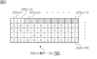
スロット盤テーブル722は、スロット群管理テーブル721の各行で管理される複数のスロット番号を碁盤の目で示したテーブルである。例えば、スロット群管理テーブル721によって50スロットずつ管理されている場合には、スロット1から50までが1枚のスロット盤テーブル722に管理され、続いてスロット51から100までが次のスロット盤テーブル722によって管理されていることになる。このスロット盤テーブル722が仮想ボリュームと関連づけられている場合には、割り当て済領域「1」が表示される。逆に、仮想ボリュームと関連づけられていない場合には、未割り当て領域「0」が表示される。
(3-3) Slot Board Table The slot board table 722 is a table in which a plurality of slot numbers managed in each row of the slot group management table 721 are shown in a grid pattern. For example, when 50 slots are managed by the slot group management table 721,
例えば、図6に示すスロット盤テーブル722では、スロット番号「3〜10」に割り当て済領域「1」が表示される。 For example, in the slot board table 722 shown in FIG. 6, the assigned area “1” is displayed for the slot numbers “3 to 10”.
(3−4)スロットテーブル
スロットテーブル723は、スロット番号毎に設けられるテーブルであって、任意のスロット番号に割り当てられる実ボリュームアドレスを格納するテーブルである。スロットテーブル723は、「スロット番号」欄7230と「実ボリュームアドレス」欄7231とから構成されている。
(3-4) Slot Table The slot table 723 is a table provided for each slot number and stores a real volume address assigned to an arbitrary slot number. The slot table 723 includes a “slot number”
例えば、図7のスロットテーブル723には、スロット番号「3」に割り当てられる実ボリュームアドレス「0000」が格納されている。 For example, the real volume address “0000” assigned to the slot number “3” is stored in the slot table 723 of FIG.
(3−5)ペア設定テーブル
ペア設定テーブル724は、コピー元の記憶領域とコピー先の記憶領域とのペア設定を管理するためのテーブルである。ペア設定テーブル724は、「スロット番号」欄7240、「コピー元のアドレス」欄7241、「コピー先のアドレス」欄7242から構成される。
(3-5) Pair Setting Table The pair setting table 724 is a table for managing the pair setting between the copy source storage area and the copy destination storage area. The pair setting table 724 includes a “slot number”
例えば図8に示すペア設定テーブル724は、スロット番号「3」に関連づけられる正副側の記憶領域が示されている。正副の記憶領域は、それぞれアドレス「0x10」が関連付けられている。 For example, the pair setting table 724 shown in FIG. 8 shows the primary and secondary storage areas associated with the slot number “3”. The primary and secondary storage areas are associated with the address “0x10”, respectively.
(3−6)ビットマップテーブル
ビットマップテーブルMは、実ボリュームRのデータを格納する記憶領域DS(以下、データ格納領域DSという)内の状況を反映させた管理情報であり、スロット単位で碁盤の目に区切られていて管理されている。ビットマップテーブルMは、仮想ボリュームVとの関連づけがない実ボリュームに対して使用されるテーブルである。そして、ビットマップテーブルMの碁盤の目には、スロット番号が割り振られている。ビットマップテーブルMは、実ボリュームRの管理情報を格納する管理格納領域MSに格納される。なお、ビットマップテーブルはスロット単位として説明したが、仮想ボリュームのページ単位、ブロック単位といったスロット単位とは別のデータ単位で管理してもよい。
(3-6) Bitmap Table The bitmap table M is management information reflecting the situation in the storage area DS for storing the data of the real volume R (hereinafter referred to as the data storage area DS). It is divided into eyes and managed. The bitmap table M is a table used for a real volume that is not associated with the virtual volume V. A slot number is assigned to the grid of the bitmap table M. The bitmap table M is stored in a management storage area MS that stores management information of the real volume R. Although the bitmap table is described as a slot unit, it may be managed in a data unit different from a slot unit such as a virtual volume page unit or a block unit.
例えば、図9に示すように、任意の実ボリュームRにデータが格納されている場合には、データが格納される記憶領域に対応するスロット番号に「1」が格納され、データが格納されていない場合には、データが格納されていない記憶領域に対応するスロット番号に「0」が格納される。 For example, as shown in FIG. 9, when data is stored in an arbitrary real volume R, “1” is stored in the slot number corresponding to the storage area in which the data is stored, and the data is stored. If not, “0” is stored in the slot number corresponding to the storage area in which no data is stored.
(4)データ転送処理
本実施の形態では、正側仮想ボリュームPVと副側仮想ボリュームSV(第1のペア設定)、正側仮想ボリュームPVと副側実ボリュームSR(第2のペア設定)、正側実ボリュームPRと副側仮想ボリュームSR(第3のペア設定)、がペア設定をした場合における、それぞれのデータ転送処理を説明する。
(4) Data transfer processing In this embodiment, the primary virtual volume PV and secondary virtual volume SV (first pair setting), the primary virtual volume PV and secondary real volume SR (second pair setting), Each data transfer process when the primary side real volume PR and the secondary side virtual volume SR (third pair setting) are set as a pair will be described.
(4−1)第1のペア設定
まず、ストレージシステム1において、正側仮想ボリュームPVと副側仮想ボリュームSVとをペア設定とした場合のデータ転送処理について説明する。この場合に、ペア設定テーブル724のコピー元のアドレスには、正側仮想ボリュームPVのアドレスが設定され、コピー先のアドレスには、副側仮想ボリュームSVのアドレスが設定される。
(4-1) First Pair Setting First, the data transfer process when the
(4−1−1)正側ストレージ装置でのデータ転送処理
図10に示すように、正側ストレージ装置でのデータ転送処理を説明する。正側ストレージ装置5Aでのデータ転送方法は、チャネルアダプタ70Aのマイクロプロセッサ700Aがコピープログラム725に基づいて実行するものである。
(4-1-1) Data Transfer Processing in Primary Storage Device As shown in FIG. 10, data transfer processing in the primary storage device will be described. The data transfer method in the
マイクロプロセッサ700Aがホスト装置2またはストレージナビゲータ8Aからリモートコピー指示を受信すると、ビットマップテーブルMを参照して、正側仮想ボリュームPVの1つ目のスロットSは割り当て済か否かを判断する(S1)。すなわち、マイクロプロセッサ700Aは、正側仮想ボリュームPVと関連づけられた正側実ボリュームにデータが格納されているかを検索する。このとき、マイクロプロセッサ700Aは、上述した仮想ボリューム管理テーブル720A、スロット群管理テーブル721A、スロット盤テーブル722A及びスロットテーブル723Aがコピー対象のスロットSに割り当てられているか否かを検索する。
When the
マイクロプロセッサ700Aがコピー対象のスロットSは割り当て済であると判断すると(S1:Yes)、データが正側実ボリュームPRに格納されているので、正側仮想ボリュームPVと関連づけられる正側実ボリュームPRのアドレスからデータを読み出す(S2)。関連づけされた正側実ボリュームPRのアドレスは、上述したスロットテーブル723を用いて検索する。
If the
マイクロプロセッサ700Aは、ペア設定テーブル724を参照し、読み出したデータをペア対象の副側仮想ボリュームSVに送信する(S3)。
The
ここで、ペア対象の副側仮想ボリュームSVに送信する際の情報を図11に示す。送信情報SI1は、初期コピーであることを副側のストレージ装置5Bに通知するための「オペレーションコード」SI10、コピーデータの有無を通知する「サブ情報」SI11、コピー元のアドレス情報である「アドレス情報」SI12、及び、「ユーザデータ」SI13から構成される。
Here, FIG. 11 shows information when transmitting to the secondary virtual volume SV to be paired. The transmission information SI1 includes an “operation code” SI10 for notifying the
ステップS3は、コピーデータを送信する場合なので、「サブ情報」SI11には「コピーデータあり」という情報が格納される。また、「アドレス情報」SI12には、コピー開始位置である正側実ボリュームPVの先頭スロット番号が格納される。そして、「ユーザデータ」SI13には、1スロットS分のデータが格納される。 Since step S3 is a case where copy data is transmitted, information “with copy data” is stored in the “sub-information” SI11. Further, the “address information” SI12 stores the leading slot number of the primary real volume PV that is the copy start position. The “user data” SI13 stores data for one slot S.
一方、マイクロプロセッサ700Aは、コピー対象のスロットSは未割り当てであると判断すると(S1:No)、データが正側実ボリュームPRには格納されていないので、コピー対象の正側仮想ボリュームPVの記憶領域(スロットS)にはデータが格納されていない旨の「未割り当てデータのメッセージ」を副側のストレージ装置5Bに送信する(S4)。
On the other hand, when the
ここで、ペア対象の副側仮想ボリュームSVに送信する際の情報を図12に示す。未割り当てデータのメッセージである送信情報SI2は、「オペレーションコード」SI20、「サブ情報」SI21、及び、コピー元のアドレス情報である「アドレス情報」SI22から構成される。 Here, FIG. 12 shows information at the time of transmission to the secondary virtual volume SV to be paired. Transmission information SI2, which is a message of unallocated data, is composed of “operation code” SI20, “sub information” SI21, and “address information” SI22 which is address information of the copy source.
ステップS4は、コピーデータを送信せず、メッセージのみを送信する場合なので、「サブ情報」SI21には「コピーデータなし」という情報が格納される。また、「アドレス情報」SI22には、データの格納有無を検索した正側実ボリュームPVの先頭スロット番号が格納される。 Since step S4 is a case where only the message is transmitted without transmitting the copy data, information “no copy data” is stored in the “sub-information” SI21. Further, the “address information” SI22 stores the leading slot number of the primary real volume PV searched for data storage presence / absence.
そうして、マイクロプロセッサ700Aは、全てのスロットSに対して割り当て済か否かを判断して(S5)、全てのスロットSに対してチェックをしていないと判断すると(S5:No)、次のチェック対象のスロットSに対して再びステップS1からステップS4までの処理を実行する。
Then, the
マイクロプロセッサ700Aは、全てのスロットSに対して割り当て済か否かを判断すると(S5:Yes)、正側のストレージ装置5Aのデータ転送処理を終了する。
When the
(4−1−2)副側のストレージ装置でのデータ転送処理
引き続き、図13に示すように、副側のストレージ装置5Bでのデータ転送処理を説明する。副側ストレージ装置5Bでのデータ転送方法は、チャネルアダプタ70Bのマイクロプロセッサ700Bがコピープログラム725に基づいて実行するものである。
(4-1-2) Data Transfer Processing in Secondary Storage Device Next, as shown in FIG. 13, data transfer processing in the
まず、マイクロプロセッサ700Bが正側のストレージ装置5Aからデータを受信したと判断すると(S10:Yes)、ペア設定テーブル724を参照し、コピー対象の副側仮想ボリュームSVを検索する。その後、マイクロプロセッサ700Bは、ビットマップテーブルMを参照して、検索した副側仮想ボリュームSV内のスロットSが既に副側実ボリュームSRに割り当てられているか否かを判断する(S11)。このとき、マイクロプロセッサ700Bは、上述した仮想ボリューム管理テーブル720B、スロット群管理テーブル721B、スロット盤テーブル722B及びスロットテーブル723Bがコピー対象のスロットSに割り当てられているか否かを検索する。
First, when the
マイクロプロセッサ700Bが検索した副側仮想ボリュームSV内のスロットSが副側実ボリュームSRに割り当てられていない場合には(S11:No)、副側実ボリュームSR内にデータが格納されていないことを示すので、副側実ボリュームSR内にデータ格納領域DSを確保する(S12)。このとき、マイクロプロセッサ700Bは、確保した副側実ボリュームSRの記憶領域と副側仮想ボリュームSVとの関係を、仮想ボリューム管理テーブル720B、スロット群管理テーブル721B、スロット盤テーブル722B及びスロットテーブル723Bに設定する。
If the slot S in the secondary virtual volume SV searched by the
その後、マイクロプロセッサ700Bは、受信したデータを確保した副側実ボリュームSRのデータ格納領域DSに書き込んで(S13)、データ転送処理を終了する。
Thereafter, the
一方、マイクロプロセッサ700Bが検索した副側仮想ボリュームSV内のスロットSが既に割り当てられている場合には(S11:Yes)、受信したデータを関連づけられた副側実ボリュームSR内のデータ格納領域DSに書き込んで(S13)、データ転送処理を終了する。
On the other hand, when the slot S in the secondary virtual volume SV searched by the
ステップS10において、マイクロプロセッサ700Bが正側のストレージ装置5Aからデータは受信していないが(S10:No)、未割り当てデータのメッセージを受信した場合には(S14:Yes)、ペア設定テーブル724を参照し、コピー対象の副側仮想ボリュームSVを検索する。その後、マイクロプロセッサ700Bは、仮想ボリューム管理テーブル720B、スロット群管理テーブル721B、スロット盤テーブル722B及びスロットテーブル723Bを参照して、検索した副側仮想ボリュームSV内のスロットSが既に副側実ボリュームSRに割り当てられているか否かを判断する(S15)。
In step S10, if the
マイクロプロセッサ700Bが検索した副側仮想ボリュームSV内のスロットSが既に割り当てられている場合には(S15:Yes)、関連づけられた実ボリュームSR内のデータ格納領域DSにゼロデータを書き込んで(S16)、データ転送処理を終了する。
If the slot S in the secondary virtual volume SV searched by the
このように、ペアとして正側及び副側ともに仮想ボリュームVを設定することで、ストレージシステム1は、実ボリュームRの容量以上を仮想ボリュームVの容量として作成できるため、将来的に増大するボリューム容量をも考慮して予め大容量の仮想ボリュームVを作成しておくことができる。
Thus, by setting the virtual volume V on both the primary side and the secondary side as a pair, the
また、正側のストレージ装置5Aは、正側仮想ボリュームPV内の未割り当て領域については未割り当てデータメッセージを副側のストレージ装置5Bに転送するのみで足りるため、副側のストレージ装置5B側ではデータ処理が不要となり、転送時間や副側での処理時間が大幅に削減できる。
Further, since the
(4−2)第2のペア設定
では次に、ストレージシステム1において、正側仮想ボリュームPVと副側実ボリュームSRとをペア設定とした場合のデータ転送処理について説明する。この場合に、ペア設定テーブル724のコピー元のアドレスには、正側仮想ボリュームPVのアドレスが設定され、コピー先のアドレスには、副側実ボリュームSRのアドレスが設定される。
(4-2) Second Pair Setting Next, the data transfer process when the primary virtual volume PV and the secondary real volume SR are set as a pair in the
(4−2−1)正側ストレージ装置でのデータ転送処理
正側ストレージ装置でのデータ転送処理は、上述したステップS1からステップS5までの処理と同様の処理手順なので、説明を省略する。
(4-2-1) Data Transfer Processing in the Primary Storage Device The data transfer processing in the primary storage device is the same processing procedure as the processing from step S1 to step S5 described above, and thus description thereof is omitted.
(4−2−2)副側ストレージ装置でのデータ転送処理
引き続き、図14に示すように、副側のストレージ装置5Bでのデータ転送処理を説明する。副側ストレージ装置5Bでのデータ転送方法は、チャネルアダプタ70Bのマイクロプロセッサ700Bがコピープログラム725Bに基づいて実行するものである。
(4-2-2) Data Transfer Processing in Secondary Storage Device Next, the data transfer processing in the
まず、マイクロプロセッサ700Bが正側のストレージ装置5Aからの送信情報SI1からデータを受信したと判断すると(S20:Yes)、ペア設定テーブル724Bを参照し、コピー対象の副側実ボリュームSRを検索する。
First, when the
その後、マイクロプロセッサ700Bは、検索した副側実ボリュームSR内のアドレスが示すデータ格納領域DSに受信したデータを書き込むと(S21)、データ転送処理を終了する。
Thereafter, when the
ステップS20において、マイクロプロセッサ700Bが正側のストレージ装置5Aからの送信情報SI2に基づいて、データは受信していないが(S20:No)、未割り当てデータのメッセージを受信したと判断すると(S22:Yes)、検索した副側実ボリュームSR内のアドレスが示すデータ格納領域DSにゼロデータを書き込み(S23)、データ転送処理を終了する。
In step S20, based on the transmission information SI2 from the
また、図15に示すように、副側のストレージ装置5Bがクイックフォーマット処理を実行することも可能である。クイックフォーマット処理とは、副側実ボリュームSRのデータ格納領域DS内のデータを消去する処理である。
Also, as shown in FIG. 15, the
具体的には、ステップS20において、マイクロプロセッサ700Bが正側のストレージ装置5Aからの送信情報SI2に基づいて、データは受信していないが(S20:No)、未割り当てデータのメッセージを受信したと判断すると(S22:Yes)、副側実ボリュームSRのデータ格納領域に格納されるデータを消去する(S24)。このとき、マイクロプロセッサ700Bは、副側実ボリュームSRに格納されるビットマップテーブルMの対象スロットSを「0」に設定する。
Specifically, in step S20, the
そうして、マイクロプロセッサ700Bは、データ転送処理を終了する。
Then, the
このように、ペアとして正側には仮想ボリュームV、副側には実ボリュームRを設定することで、正側のストレージ装置5Aは、正側仮想ボリュームPV内の未割り当て領域については未割り当てデータメッセージを副側のストレージ装置5Bに転送するのみで足りる。また副側のストレージ装置5B側ではゼロデータをペア設定されたデータ格納領域DSに書き込むだけでいいので、データ転送処理が不要となり、転送時間が削減できる。
In this way, by setting the virtual volume V on the primary side and the real volume R on the secondary side as a pair, the
(4−3)第3のペア設定
次に、ストレージシステム1において、正側実ボリュームPRと副側仮想ボリュームSVとをペア設定とした場合のデータ転送処理について説明する。この場合に、ペア設定テーブル724のコピー元のアドレスには、正側実ボリュームPRのアドレスが設定され、コピー先のアドレスには、副側仮想ボリュームSVのアドレスが設定される。
(4-3) Third Pair Setting Next, a data transfer process in the
(4−3−1)正側ストレージ装置でのデータ転送処理
図16に示すように、正側ストレージ装置でのデータ転送処理を説明する。正側ストレージ装置5Aでのデータ転送方法は、チャネルアダプタ70Aのマイクロプロセッサ700Aがコピープログラム725に基づいて実行するものである。
(4-3-1) Data Transfer Processing in Primary Storage Device As shown in FIG. 16 , data transfer processing in the primary storage device will be described. The data transfer method in the
マイクロプロセッサ700Aがホスト装置2またはストレージナビゲータ8Aからリモートコピー指示を受信すると、ビットマップテーブルMを正側実ボリュームPRの管理格納領域MSからから読み出し、正側実ボリュームPRのコピー対象となる1つ目のスロットSはゼロであるか否かを判断する(S30)。つまり、マイクロプロセッサ700Aは、1つ目のスロットS位置に対応するデータ格納領域DSにはデータが格納されていないか否かを検索する。
When the
マイクロプロセッサ700Aがコピー対象となる1つ目のスロットSはゼロであると判断すると(S30:Yes)、「未割り当てデータのメッセージ」を送信情報SI2として副側のストレージ装置5Bに送信する(S31)。
If the
一方、マイクロプロセッサ700Aがコピー対象となる1つ目のスロットSに対応するデータ格納領域DSにデータがあると判断すると(S30:No)、そのデータ格納領域DSからデータを読み出し(S32)、読み出したデータを送信情報SI1として副側のストレージ装置5Bに送信する(S33)。
On the other hand, when the
そうして、マイクロプロセッサ700Aは、全てのスロットSに対して割り当て済か否かを判断して(S34)、全てのスロットSに対してチェックをしていないと判断すると(S34:No)、次のチェック対象のスロットSに対して再びステップS30からステップS33までの処理を実行する。
Then, the
マイクロプロセッサ700Aは、全てのスロットSに対して割り当て済か否かを判断すると(S34:No)、正側のストレージ装置5Aのデータ転送処理を終了する。
When the
(4−3−2)副側ストレージ装置でのデータ転送処理
副側ストレージ装置でのデータ転送処理は、上述したステップS20からステップS24までの処理と同様の処理手順なので、説明を省略する。
(4-3-2) Data Transfer Processing in Secondary Storage Device The data transfer processing in the secondary storage device is the same processing procedure as the processing from step S20 to step S24 described above, and thus description thereof is omitted.
このように、ペアとして正側には実ボリュームR、副側には仮想ボリュームRを設定することで、正側のストレージ装置5Aは、正側実ボリュームPR内でデータが格納されていない領域を検索し、データが格納されていない領域については「未割り当てデータメッセージ」を副側のストレージ装置5Bに転送するのみで足りる。また副側のストレージ装置5B側ではゼロデータをペア設定されたデータ格納領域DSに書き込むだけでいいので、データ転送処理が不要となり、転送時間が削減できる。
In this way, by setting the real volume R on the primary side and the virtual volume R on the secondary side as a pair, the
(5)本実施の形態の効果
以上のように、本実施の形態では、ペア設定時に、正側のストレージ装置内に格納されるデータのみを副側のストレージ装置に転送するため、データ転送に伴うストレージシステムの負荷を削減することができる。
(5) Effects of this embodiment As described above, in this embodiment, only data stored in the primary storage apparatus is transferred to the secondary storage apparatus at the time of pair setting. The load of the accompanying storage system can be reduced.
本発明は、1又は複数のストレージ装置を有するストレージシステムや、その他の形態のストレージシステムに広く適用することができる。 The present invention can be widely applied to a storage system having one or a plurality of storage devices and other forms of storage systems.
1……ストレージシステム、2……ホスト装置、3……ネットワーク、4……コピー用のネットワーク、5A……正側のストレージ装置、5B……副側のストレージ装置、60A、60B……ハードディスク、70……チャネルアダプタ、700……マイクロプロセッサ、71……スイッチ、72……共有メモリ、73……キャッシュメモリ、74……ディスクアダプタ、8……ストレージナビゲータ、80……管理画面、720……仮想ボリューム管理テーブル、721……スロット群管理テーブル、722……スロット盤テーブル、723……スロットテーブル、724……ペア設定テーブル、725……コピープログラム、M……ビットマップテーブル、DS……データ格納領域、MS……管理格納領域。
DESCRIPTION OF
Claims (6)
前記正側の論理ボリュームとペア設定される副側の仮想ボリュームを提供し、前記正側の論理ボリュームに格納された前記データを前記副側の仮想ボリュームにコピーする際、前記副側の仮想ボリュームに動的に副側の実ボリュームから記憶領域を割り当て、割り当てた前記記憶領域に前記データを格納する副側のストレージ装置と
を備え、
前記正側の論理ボリューム、前記副側の仮想ボリュームおよび前記副側の実ボリュームは、それぞれ記憶領域が複数のスロット領域に区切られており、
前記正側の論理ボリュームと前記副側の仮想ボリュームとをペア設定した場合の初期コピー時、
前記正側のストレージ装置は、
前記正側の論理ボリュームの前記スロット領域毎にデータの有無を検索し、
前記スロット領域にデータが格納されていない場合に、前記データが格納されていない通知を前記副側のストレージ装置に送信し、
前記副側のストレージ装置は、
前記正側のストレージ装置から前記通知を受信した場合に、前記副側の仮想ボリュームの前記スロット領域のうち、前記データをコピーすべき前記スロット領域に前記副側の実ボリュームから記憶領域が既に割り当てられている場合には、当該記憶領域にゼロデータを書き込み、当該スロット領域に前記実ボリュームから記憶領域が割り当てられていない場合には、何もしない
ことを特徴とするストレージシステム。 Providing the logical volume of the primary side, the primary storage apparatus for storing data from said host device to said primary logical volume,
Providing a secondary virtual volume paired with the primary logical volume, and copying the data stored in the primary logical volume to the secondary virtual volume; A storage device that dynamically allocates a storage area from the real volume on the secondary side and stores the data in the allocated storage area ;
With
Each of the primary logical volume, the secondary virtual volume, and the secondary real volume has a storage area divided into a plurality of slot areas,
During the initial copy when the primary logical volume and the secondary virtual volume are paired,
The primary storage device is
Searching the existence of data before Symbol slots each region of the primary logical volume,
Previously transmitted when a data kissing lot area is not stored, a notification said data is not stored in said secondary storage device,
The secondary storage device is
When the notification is received from the primary storage apparatus, a storage area is already allocated from the secondary real volume to the slot area to which the data is to be copied among the slot areas of the secondary virtual volume. the storage system is when is the write the zero data into the storage area, if the corresponding slot region and the no memory space is allocated from the real volume, characterized in that to do nothing.
前記正側の論理ボリュームが仮想ボリュームの場合には、前記正側の論理ボリュームの前記スロット領域と、前記データが格納される正側の実ボリュームのスロット領域とを関連づける正側関連づけ情報を有し、
当該正側関連づけ情報に基づいて、前記正側の論理ボリュームの前記スロット領域ごとのデータの有無を検索する
ことを特徴とする請求項1に記載のストレージシステム。 The primary storage device is
When the primary logical volume is a virtual volume, it has primary association information that associates the slot area of the primary logical volume with the slot area of the primary real volume in which the data is stored. ,
2. The storage system according to claim 1, wherein presence / absence of data for each slot area of the primary logical volume is searched based on the primary association information .
前記正側の論理ボリュームが実ボリュームの場合には、前記正側の実ボリュームのスロット領域単位で前記データの有無を管理する管理情報を有し、
当該管理情報に基づいて、前記正側の論理ボリュームの前記スロット領域ごとのデータの有無を検索する
ことを特徴とする請求項1に記載のストレージシステム。 The primary storage device is
In the case where the primary logical volume is a real volume, it has management information for managing the presence or absence of the data in slot area units of the primary real volume,
2. The storage system according to claim 1 , wherein the presence / absence of data for each slot area of the primary logical volume is searched based on the management information .
前記正側の論理ボリューム、前記副側の仮想ボリュームおよび前記副側の実ボリュームは、それぞれ記憶領域が複数のスロット領域に区切られており、Each of the primary logical volume, the secondary virtual volume, and the secondary real volume has a storage area divided into a plurality of slot areas,
前記正側の論理ボリュームと前記副側の仮想ボリュームとをペア設定した場合の初期コピー時、During the initial copy when the primary logical volume and the secondary virtual volume are paired,
前記正側のストレージ装置が、前記正側の論理ボリュームの前記スロット領域毎にデータの有無を検索する検索ステップと、A search step in which the primary storage device searches for data for each slot area of the primary logical volume;
前記正側のストレージ装置が、前記スロット領域にデータが格納されていない場合に、前記データが格納されていない通知を前記副側のストレージ装置に送信する送信ステップと、A transmission step of transmitting a notification that the data is not stored to the secondary storage device when the primary storage device does not store data in the slot area;
前記副側のストレージ装置が、前記正側のストレージ装置から前記通知を受信した場合に、前記副側の仮想ボリュームの前記スロット領域のうち、前記データをコピーすべき前記スロット領域に前記副側の実ボリュームから記憶領域が既に割り当てられている場合には、当該記憶領域にゼロデータを書き込み、当該スロット領域に前記実ボリュームから記憶領域が割り当てられていない場合には、何もしない書き込みステップとWhen the secondary storage apparatus receives the notification from the primary storage apparatus, out of the slot areas of the secondary virtual volume, the secondary storage apparatus is copied to the slot area to which the data is to be copied. When a storage area is already allocated from the real volume, zero data is written to the storage area, and when a storage area is not allocated from the real volume to the slot area, nothing is written.
を備えることを特徴とするコピー方法。A copy method comprising:
前記正側の論理ボリュームが仮想ボリュームの場合には、前記正側の論理ボリュームの前記スロット領域と、前記データが格納される正側の実ボリュームのスロット領域とを関連づける正側関連づけ情報を有し、When the primary logical volume is a virtual volume, it has primary association information that associates the slot area of the primary logical volume with the slot area of the primary real volume in which the data is stored. ,
前記検索ステップにおいて、前記正側のストレージ装置は、In the search step, the primary storage device is
当該正側関連づけ情報に基づいて、前記正側の論理ボリュームの前記スロット領域ごとのデータの有無を検索するBased on the primary side association information, the presence / absence of data for each slot area of the primary logical volume is searched.
ことを特徴とする請求項4に記載のコピー方法。The copying method according to claim 4, wherein:
前記正側の論理ボリュームが実ボリュームの場合には、前記正側の実ボリュームのスロット領域単位で前記データの有無を管理する管理情報を有し、In the case where the primary logical volume is a real volume, it has management information for managing the presence or absence of the data in slot area units of the primary real volume,
前記検索ステップにおいて、前記正側のストレージ装置は、In the search step, the primary storage device is
当該管理情報に基づいて、前記正側の論理ボリュームの前記スロット領域ごとのデータの有無を検索するBased on the management information, the presence or absence of data for each slot area of the primary logical volume is searched.
ことを特徴とする請求項4に記載のコピー方法。The copying method according to claim 4, wherein:
Priority Applications (5)
| Application Number | Priority Date | Filing Date | Title |
|---|---|---|---|
| JP2008046724A JP5317495B2 (en) | 2008-02-27 | 2008-02-27 | Storage system, copy method, and primary storage apparatus |
| US12/112,478 US8127102B2 (en) | 2008-02-27 | 2008-04-30 | Storage system, copy method, and primary storage apparatus |
| EP08171196A EP2096529A3 (en) | 2008-02-27 | 2008-12-10 | Storage system, copy method, and primary storage apparatus |
| CN2009100048353A CN101520713B (en) | 2008-02-27 | 2009-01-19 | Storage system, copy method, and primary storage apparatus |
| US13/296,461 US8316205B2 (en) | 2008-02-27 | 2011-11-15 | Storage system, copy method, and primary storage apparatus |
Applications Claiming Priority (1)
| Application Number | Priority Date | Filing Date | Title |
|---|---|---|---|
| JP2008046724A JP5317495B2 (en) | 2008-02-27 | 2008-02-27 | Storage system, copy method, and primary storage apparatus |
Publications (2)
| Publication Number | Publication Date |
|---|---|
| JP2009205415A JP2009205415A (en) | 2009-09-10 |
| JP5317495B2 true JP5317495B2 (en) | 2013-10-16 |
Family
ID=40677537
Family Applications (1)
| Application Number | Title | Priority Date | Filing Date |
|---|---|---|---|
| JP2008046724A Expired - Fee Related JP5317495B2 (en) | 2008-02-27 | 2008-02-27 | Storage system, copy method, and primary storage apparatus |
Country Status (4)
| Country | Link |
|---|---|
| US (2) | US8127102B2 (en) |
| EP (1) | EP2096529A3 (en) |
| JP (1) | JP5317495B2 (en) |
| CN (1) | CN101520713B (en) |
Cited By (1)
| Publication number | Priority date | Publication date | Assignee | Title |
|---|---|---|---|---|
| JPH0664405B2 (en) | 1984-07-13 | 1994-08-22 | キヤノン株式会社 | Transfer device |
Families Citing this family (5)
| Publication number | Priority date | Publication date | Assignee | Title |
|---|---|---|---|---|
| JP5317495B2 (en) | 2008-02-27 | 2013-10-16 | 株式会社日立製作所 | Storage system, copy method, and primary storage apparatus |
| WO2010054297A1 (en) * | 2008-11-07 | 2010-05-14 | Compellent Technologies | Thin import for a data storage system |
| JP5540636B2 (en) * | 2009-10-02 | 2014-07-02 | 日本電気株式会社 | Storage system, storage device, storage content replication method and program for storage device |
| US9965224B2 (en) * | 2010-02-24 | 2018-05-08 | Veritas Technologies Llc | Systems and methods for enabling replication targets to reclaim unused storage space on thin-provisioned storage systems |
| JP2016212548A (en) | 2015-05-01 | 2016-12-15 | 富士通株式会社 | Storage control device, storage control method, and storage control program |
Family Cites Families (8)
| Publication number | Priority date | Publication date | Assignee | Title |
|---|---|---|---|---|
| JP3414218B2 (en) | 1997-09-12 | 2003-06-09 | 株式会社日立製作所 | Storage controller |
| JP4175788B2 (en) | 2001-07-05 | 2008-11-05 | 株式会社日立製作所 | Volume controller |
| JP2006127028A (en) | 2004-10-27 | 2006-05-18 | Hitachi Ltd | Storage system and storage control device |
| JP4955996B2 (en) * | 2005-09-20 | 2012-06-20 | 株式会社日立製作所 | Volume migration method and storage network system |
| JP4942371B2 (en) * | 2006-03-23 | 2012-05-30 | 株式会社日立製作所 | Storage system and data management method |
| JP4835249B2 (en) | 2006-04-26 | 2011-12-14 | 株式会社日立製作所 | Storage system, remote copy, and management method |
| JP4899711B2 (en) | 2006-08-11 | 2012-03-21 | 大日本印刷株式会社 | Management system, server and program |
| JP5317495B2 (en) | 2008-02-27 | 2013-10-16 | 株式会社日立製作所 | Storage system, copy method, and primary storage apparatus |
-
2008
- 2008-02-27 JP JP2008046724A patent/JP5317495B2/en not_active Expired - Fee Related
- 2008-04-30 US US12/112,478 patent/US8127102B2/en not_active Expired - Fee Related
- 2008-12-10 EP EP08171196A patent/EP2096529A3/en not_active Withdrawn
-
2009
- 2009-01-19 CN CN2009100048353A patent/CN101520713B/en not_active Expired - Fee Related
-
2011
- 2011-11-15 US US13/296,461 patent/US8316205B2/en not_active Expired - Fee Related
Cited By (1)
| Publication number | Priority date | Publication date | Assignee | Title |
|---|---|---|---|---|
| JPH0664405B2 (en) | 1984-07-13 | 1994-08-22 | キヤノン株式会社 | Transfer device |
Also Published As
| Publication number | Publication date |
|---|---|
| US20120059987A1 (en) | 2012-03-08 |
| EP2096529A3 (en) | 2011-04-06 |
| CN101520713A (en) | 2009-09-02 |
| JP2009205415A (en) | 2009-09-10 |
| EP2096529A2 (en) | 2009-09-02 |
| US20090216972A1 (en) | 2009-08-27 |
| US8127102B2 (en) | 2012-02-28 |
| US8316205B2 (en) | 2012-11-20 |
| CN101520713B (en) | 2013-09-04 |
Similar Documents
| Publication | Publication Date | Title |
|---|---|---|
| JP4341897B2 (en) | Storage device system and data replication method | |
| EP2399190B1 (en) | Storage system and method for operating storage system | |
| JP4738941B2 (en) | Storage system and storage system management method | |
| US6598174B1 (en) | Method and apparatus for storage unit replacement in non-redundant array | |
| US8099569B2 (en) | Storage system and data migration method | |
| US7853765B2 (en) | Storage system and data management method | |
| JP2005309550A (en) | Remote copy method and remote copy system | |
| JP5228466B2 (en) | Backup device, backup method and backup program | |
| JP2010097372A (en) | Volume management system | |
| JP5317495B2 (en) | Storage system, copy method, and primary storage apparatus | |
| EP2157504A2 (en) | Virtual disk management program, storage device management program, multinode storage system, and virtual disk managing method | |
| US7660946B2 (en) | Storage control system and storage control method | |
| JP2012198639A (en) | Control apparatus, control method, and storage apparatus | |
| JP5159353B2 (en) | Storage system, release method, and secondary storage device | |
| JP4920979B2 (en) | Storage apparatus and control method thereof | |
| JPWO2011048641A1 (en) | Remote copy system and remote copy control method | |
| JP2013069096A (en) | Controller, control method, and storage device | |
| JP5052257B2 (en) | Storage system and storage control device | |
| JP5838652B2 (en) | Data copy processing system | |
| US7721056B2 (en) | Storage system, disk array apparatus, volume presentation method, and data consistency confirmation method | |
| US7546433B2 (en) | Storage system, and data management and migration method | |
| JP2006079193A (en) | Storage device system | |
| JPWO2005006175A1 (en) | Method for grouping a plurality of logical units, method for processing received requests, device for grouping a plurality of logical units, and device for processing received requests | |
| WO2015068217A1 (en) | Management system and method |
Legal Events
| Date | Code | Title | Description |
|---|---|---|---|
| A621 | Written request for application examination |
Free format text: JAPANESE INTERMEDIATE CODE: A621 Effective date: 20100903 |
|
| A131 | Notification of reasons for refusal |
Free format text: JAPANESE INTERMEDIATE CODE: A131 Effective date: 20130312 |
|
| A521 | Request for written amendment filed |
Free format text: JAPANESE INTERMEDIATE CODE: A523 Effective date: 20130509 |
|
| TRDD | Decision of grant or rejection written | ||
| A01 | Written decision to grant a patent or to grant a registration (utility model) |
Free format text: JAPANESE INTERMEDIATE CODE: A01 Effective date: 20130611 |
|
| A61 | First payment of annual fees (during grant procedure) |
Free format text: JAPANESE INTERMEDIATE CODE: A61 Effective date: 20130709 |
|
| R150 | Certificate of patent or registration of utility model |
Ref document number: 5317495 Country of ref document: JP Free format text: JAPANESE INTERMEDIATE CODE: R150 Free format text: JAPANESE INTERMEDIATE CODE: R150 |
|
| LAPS | Cancellation because of no payment of annual fees |