JP5306003B2 - Pair of shielded connectors - Google Patents
Pair of shielded connectors Download PDFInfo
- Publication number
- JP5306003B2 JP5306003B2 JP2009065322A JP2009065322A JP5306003B2 JP 5306003 B2 JP5306003 B2 JP 5306003B2 JP 2009065322 A JP2009065322 A JP 2009065322A JP 2009065322 A JP2009065322 A JP 2009065322A JP 5306003 B2 JP5306003 B2 JP 5306003B2
- Authority
- JP
- Japan
- Prior art keywords
- connector
- housing
- lock
- lock lever
- fitting
- Prior art date
- Legal status (The legal status is an assumption and is not a legal conclusion. Google has not performed a legal analysis and makes no representation as to the accuracy of the status listed.)
- Active
Links
Images


Landscapes
- Details Of Connecting Devices For Male And Female Coupling (AREA)
Description
本発明は、電気コネクタの技術分野に属し、導電性のシェルにより覆われたシールドコネクタに関する。 The present invention belongs to the technical field of electrical connectors and relates to a shielded connector covered with a conductive shell.
特許文献1は、ロック機構を備えたプラグコネクタとレセプタクルコネクタとを開示している。同文献の段落0019ないし0021に記載されているように、プラグコネクタ2は、樹脂製のプラグハウジング20と、このプラグハウジング20の内部に所定のピッチ間隔で並列に配列固定された複数の雄端子50と、上記プラグハウジング20の外部を覆う金属製のプラグシェル40を備える。上記プラグハウジング20には筐体21からレセプタクルコネクタ6との嵌合方向に突出した嵌合部22が設けられ、上記嵌合部22の長手方向両端にはガイドポスト23、24が設けられ、これらガイドポスト23、24には、左右各側にて外部に突出したロック部25、26が設けられている。そして、プラグコネクタ2とレセプタクルコネクタ6の嵌合時に、これらロック部25、26は、レセプタクルコネクタ6に対応して設けられたロック孔91と係合し、これによってプラグコネクタ2とレセプタクルコネクタ6は互いにロックされる(符合は特許文献1から引用)。上記ロック部25、26はロック孔91と、特許文献1の図5に示したもの(特許文献2に開示されたものに対応する)と同様の方法で係合すると記載されている(段落0021を参照)。特許文献1の段落0002ないし0005によると、特許文献1の図5に示されたロック機構の場合、ロックレバー145のフック部147が、ハウジング140の外部を略筒状に覆うシェル160の折込部163のロック孔170に嵌るようになっている。特許文献2によれば、同文献に開示された各レバー140は(符合は特許文献2から引用)、金属板をプレス加工して製作される(段落0058を参照)。
Patent Document 1 discloses a plug connector and a receptacle connector provided with a lock mechanism. As described in the paragraphs 0019 to 0021 of the same document, the plug connector 2 includes a resin plug housing 20 and a plurality of male terminals arranged and fixed in parallel at a predetermined pitch inside the plug housing 20. 50 and a metal plug shell 40 that covers the outside of the plug housing 20. The plug housing 20 is provided with a fitting portion 22 that protrudes from the housing 21 in the fitting direction with the receptacle connector 6, and guide posts 23 and 24 are provided at both longitudinal ends of the fitting portion 22. The guide posts 23 and 24 are provided with lock portions 25 and 26 that protrude outward on the left and right sides. When the plug connector 2 and the receptacle connector 6 are fitted, the lock portions 25 and 26 engage with lock holes 91 provided corresponding to the receptacle connector 6, whereby the plug connector 2 and the receptacle connector 6 are engaged with each other. They are locked to each other (the reference is quoted from Patent Document 1). It is described that the lock portions 25 and 26 engage with the lock hole 91 in the same manner as that shown in FIG. 5 of Patent Document 1 (corresponding to that disclosed in Patent Document 2) (paragraph 0021). See). According to paragraphs 0002 to 0005 of Patent Document 1, in the case of the lock mechanism shown in FIG. 5 of Patent Document 1, the hook portion 147 of the lock lever 145 is a folded portion of the shell 160 that covers the outside of the
特許文献3は、同文献の段落0017ないし0025に記載されているように、特許文献1の上記ロック部25、26に相当するフック部34aを備えたコネクタ1と、特許文献1の上記ロック孔91に相当する相手係合孔61cを備えた相手側コネクタ61とを開示している(符合は特許文献3から引用)。このフック部34aが設けられたロック部材31は、金属板をプレスにより打ち抜き加工したものである(特許文献3の段落0027を参照)。 As described in paragraphs 0017 to 0025 of Patent Document 3, Patent Document 3 includes a connector 1 having a hook portion 34a corresponding to the lock portions 25 and 26 of Patent Document 1, and the lock hole of Patent Document 1. And a mating connector 61 provided with a mating engagement hole 61c corresponding to 91 (reference is quoted from Patent Document 3). The lock member 31 provided with the hook portion 34a is obtained by punching a metal plate with a press (see paragraph 0027 of Patent Document 3).
特許文献4は、同文献の段落0007に記載されているように、絶縁本体1と、複数導電端子5と、内遮蔽ハウジング2と、外遮蔽ハウジング3と、接地部材6などを含むレセプタクルコネクタを開示している(符合は特許文献1から引用)。 Patent Document 4 discloses a receptacle connector including an insulating body 1, a plurality of conductive terminals 5, an inner shielding housing 2, an outer shielding housing 3, a grounding member 6 and the like, as described in paragraph 0007 of the same document. It is disclosed (the reference is quoted from Patent Document 1).
特許文献1の上記ロック孔91が設けられた嵌合ロック片90はレセプタクルシェル70を折り曲げて形成されているので金属製であると理解される。上記ロック孔91に係合する上記ロック部25、26を有するロックレバーも、特許文献2のレバー140と同様に金属製であると理解される。また、特許文献3の上記フック部34aが金属製であるので、このフック部34aと係合する上記相手係合孔61cが形成された相手側係合部61bも、上記フック部34aによるカジリ等を避けるため、例えば相手側コネクタ61のシェルの一部を利用して金属で形成するのが一般的である。
The fitting lock piece 90 provided with the lock hole 91 of Patent Document 1 is understood to be made of metal since it is formed by bending the receptacle shell 70. It is understood that the lock lever having the lock portions 25 and 26 engaged with the lock hole 91 is also made of metal like the
このように一対のシールドコネクタにおいて上記ロックレバー又は上記ロック部材と、上記嵌合ロック片又は相手側係合部とを金属で形成するのではなく、ロックレバーと当該ロックレバーが係合するハウジングを合成樹脂により形成して金属により形成したときとは異質の嵌合フィーリング及び嵌合音を求める場合、一方のシールドコネクタの合成樹脂製ロックレバーを他方のシールドコネクタの合成樹脂製ハウジングに設けたロック穴に係合させることになる。その場合、ロック爪のロック穴への係合を可能とするため、ハウジングを覆うシェルに貫通口を設けることになるが、そうすると、上記貫通口の部位ではシェルによるシールド機能が損なわれることになる。そこで、上記引用文献4の上記レセプタクルコネクタのように、ハウジング及びシェルの外側にもう一つのシェルを設けて、内側のシェルに開口を設けることにより損なわれたシールド機能を外側のシェルによって補うことが考えられる。しかし、そうすると外側にシェルを設けることによりシールドコネクタのコストの増大及び大型化を招く。また、上記ロックレバーが外力を受けて損傷することを避けたいという要請もある。 In this way, in the pair of shield connectors, the lock lever or the lock member and the fitting lock piece or the mating engagement portion are not formed of metal, but a housing in which the lock lever and the lock lever are engaged is provided. To obtain a fitting feeling and fitting sound that are different from those formed from synthetic resin and metal, the synthetic resin lock lever of one shield connector is provided in the synthetic resin housing of the other shield connector. It will be engaged with the lock hole. In that case, in order to enable engagement of the lock claw with the lock hole, a through-hole is provided in the shell covering the housing, but in this case, the shield function by the shell is impaired at the portion of the through-hole. . Therefore, like the receptacle connector of the above cited reference 4, another shield is provided outside the housing and shell, and the shield function impaired by providing an opening in the inner shell is compensated by the outer shell. Conceivable. However, if it does so, the increase in the cost and enlargement of a shield connector will be caused by providing a shell on the outside. There is also a demand for avoiding damage to the lock lever due to external force.
本発明は、このような点に着目してなされたものであり、その目的とするところは、一方のシールドコネクタの合成樹脂製ロックレバーを他方のシールドコネクタの合成樹脂製ハウジングの内側に係合させることにより、コストの増大及び大型化を招いたりロックレバーが外力により損傷することを防止すると共に、合成樹脂製ロックレバーと合成樹脂製ハウジングとによる独特の嵌合フィーリング及び嵌合音を得ることができ、しかも上記ロックレバーの叩き音を増幅させて両コネクタの嵌合完了の検出をより確実に行い、半嵌合による接続不良の発生防止、コネクタの嵌合方向への強引な押し込みによるコネクタの損傷防止などを一層確実に行うことができる一対のシールドコネクタを提供することにある。 The present invention has been made paying attention to such points, and the purpose thereof is to engage the synthetic resin lock lever of one shield connector with the inside of the synthetic resin housing of the other shield connector. This prevents an increase in cost and size, and prevents the lock lever from being damaged by an external force, and provides a unique fitting feeling and fitting sound due to the synthetic resin lock lever and the synthetic resin housing. In addition, it is possible to amplify the sound of the locking lever to detect the completion of mating of both connectors, prevent the occurrence of poor connection due to half mating, and forcefully push the connector in the mating direction. to provide a pair of shielded connector that can be performed connector to prevent damage and more reliably.
上記目的を達成するため、本発明の一対のシールドコネクタは、 第1コネクタと、この第1コネクタに嵌合することになる第2コネクタとを備え、
上記第1コネクタは、合成樹脂により形成されて嵌合側の面から内方へ凹む凹部が形成された第1ハウジングと、導電性材料により形成されて上記第1ハウジングに当該第1ハウジングの外面を覆うように設けられた第1シェルと、導電性材料により形成されて上記第1ハウジングに設けられ、一端が接触部として上記凹部の内部に配置されると共に他端が外部へ接続される接続部として上記第1ハウジングに配置された第1コンタクトとを備え、
上記第2コネクタは、合成樹脂により形成されてハウジング本体と当該ハウジング本体から嵌合側へ突出して上記凹部への挿入及び上記凹部からの抜去が可能な凸部とを有する第2ハウジングと、導電性材料により形成されて上記第2ハウジングに上記ハウジング本体の外面を覆うように設けられた第2シェルと、導電性材料により形成されて上記第2ハウジングに設けられ、一端が上記第1コンタクトの上記接触部に接触することになる接触部として上記凸部に配置されると共に他端が外部へ接続される接続部として上記第2ハウジングに配置された第2コンタクトとを備え、
上記第2ハウジングの凸部は、凸部本体と、可撓性を有して上記凸部本体の嵌合側の先端から反嵌合側へ延びて、反嵌合側の端部が操作部として上記第2コネクタの上記第1コネクタへの嵌合時に上記第1コネクタの上記凹部から外部へ出るように設けられたロックレバーとを備え、
上記ロックレバーにおける嵌合側の端部と反嵌合側の端部との間の部位と、上記第1ハウジングの凹部を構成する壁における上記第2コネクタの上記第1コネクタへの嵌合時に上記ロックレバーの上記部位に対向する部位とのうち、一方の部位には他方の部位へ向かって突出するロック爪が設けられ、他方の部位には上記ロック爪が嵌ることができるロック穴が形成されており、
上記第1コネクタには、上記ロック穴に連通する空洞部が設けられており、
上記凸部の上記凹部への挿入にしたがい上記ロックレバーが上記凸部本体に接近するよう撓んでから復原することで上記ロック爪が上記ロック穴に嵌り、上記操作部を上記凸部本体に接近するよう押して上記ロックレバーを撓ませると上記ロック爪が上記ロック穴から抜けるように構成すると共に、上記ロックレバーの復原時に上記ロックレバーが上記奥壁を叩いたときに生じる叩き音が上記空洞部で共鳴するように構成している。
In order to achieve the above object, a pair of shielded connectors according to the present invention includes a first connector and a second connector to be fitted to the first connector,
The first connector is formed of a synthetic resin and has a first housing formed with a recess recessed inward from the surface on the fitting side. The first connector is formed of a conductive material and is formed on the first housing with the outer surface of the first housing. A first shell provided so as to cover the surface, a connection formed by a conductive material and provided in the first housing, with one end disposed as a contact portion inside the recess and the other end connected to the outside A first contact disposed in the first housing as a part,
The second connector is formed of a synthetic resin and has a housing main body, a second housing that protrudes from the housing main body toward the fitting side, and can be inserted into the concave portion and removed from the concave portion, and conductive A second shell formed of a conductive material so as to cover the outer surface of the housing body, and a second shell formed of a conductive material and provided on the second housing. A second contact disposed on the second housing as a connection portion disposed on the convex portion as a contact portion to be in contact with the contact portion and connected to the outside at the other end;
The convex part of the second housing has a convex part main body and has flexibility and extends from the tip of the convex part main body on the mating side to the non-fitting side. A lock lever provided so as to come out from the concave portion of the first connector when the second connector is fitted to the first connector,
At the time of fitting the second connector to the first connector in the portion of the lock lever between the fitting end and the non-fitting end and the wall constituting the recess of the first housing Of the part of the lock lever facing the part, a lock claw protruding toward the other part is provided at one part, and a lock hole into which the lock claw can be fitted is formed at the other part. Has been
The first connector is provided with a cavity communicating with the lock hole,
The lock lever is bent so as to approach the convex body as the convex portion is inserted into the concave portion, and then restored so that the lock claw fits into the lock hole, and the operating portion approaches the convex body. When the lock lever is bent so as to be bent, the lock claw is pulled out from the lock hole, and when the lock lever is restored, a hitting sound generated when the lock lever hits the back wall is generated. It is configured to resonate with .
上記第2コネクタを上記第1コネクタに嵌合する場合、上記第2コネクタの上記凸部を上記第1コネクタの上記凹部へ挿入すると、上記ロックレバーが上記凸部本体に接近するよう撓んでから復原することで上記ロック爪が上記ロック穴に嵌り、上記第2コンタクトの上記接触部が上記第1コンタクトの上記接触部に接触する。また、上記第2コネクタを上記第1コネクタから離間させる場合、上記操作部を上記凸部本体に接近するよう押して上記ロックレバーを撓ませると上記ロック爪が上記ロック穴から抜け、上記第2コネクタの上記凸部を上記第1コネクタの上記凹部から抜去することが可能となる。 When fitting the second connector to the first connector, when the convex portion of the second connector is inserted into the concave portion of the first connector, the lock lever is bent so as to approach the convex body. By restoring, the lock claw fits into the lock hole, and the contact portion of the second contact contacts the contact portion of the first contact. Further, when the second connector is separated from the first connector, the lock claw comes out of the lock hole when the operation lever is pushed close to the convex body to bend the lock lever, and the second connector It is possible to remove the convex portion from the concave portion of the first connector.
そして、上記第2コネクタを上記第1コネクタに嵌合する場合、上記ロックレバーが上記凸部本体に接近するよう撓んでから復原すると、上記ロックレバーが上記凹部を構成する壁を叩く。その場合、上記ロックレバー及び上記壁はいずれも合成樹脂により形成されているので、上記ロックレバーが上記壁を擦ってから上記壁を叩くまでの間に第2コネクタから得られる嵌合フィーリングと、上記ロックレバーが上記壁を叩くことで発生する嵌合音とが、上記ロックレバー及び上記壁をいずれも金属により形成した場合とは全く異質のものとなる。 When the second connector is fitted into the first connector, when the lock lever is bent so as to approach the convex body and then restored, the lock lever strikes the wall that forms the concave portion. In that case, since both the lock lever and the wall are made of synthetic resin, the fitting feeling obtained from the second connector after the lock lever rubs the wall and hits the wall; The fitting sound generated when the lock lever strikes the wall is completely different from the case where both the lock lever and the wall are made of metal.
また、上記凹部の内側において上記ロック爪と上記ロック穴との嵌合と解除とが行われるので、上記第1シェル及び上記第2シェルに上記ロック爪と上記ロック穴とを嵌合させるための開口を設ける必要がない。そのため、上記第1シェル及び上記第2シェルによるシールド機能を高めることが可能となる。その場合、上記引用文献4の上記レセプタクルコネクタのように、ハウジング及びシェルの外側にもう一つのシェルを設ける必要がないのでシールドコネクタのコストの増大及び大型化を防ぐことができる。さらに、上記第2コネクタを上記第1コネクタに嵌合すると上記ロックレバーが上記凹部に収まるので、上記ロックレバーが外力を受けて損傷するおそれがない。 In addition, since the lock claw and the lock hole are fitted and released inside the recess, the lock claw and the lock hole are fitted to the first shell and the second shell. There is no need to provide an opening. Therefore, it is possible to enhance the shielding function by the first shell and the second shell. In this case, unlike the receptacle connector of the above cited reference 4, it is not necessary to provide another shell outside the housing and the shell, so that an increase in cost and an increase in size of the shield connector can be prevented. Further, when the second connector is fitted to the first connector, the lock lever is received in the recess, so that there is no possibility that the lock lever is damaged by receiving an external force.
さらに、上記第1コネクタに、上記ロック穴に連通する空洞部を設けたので、上記第2コネクタを上記第1コネクタに嵌合する場合、上記ロックレバーが上記凸部本体に接近するよう撓んでから復原すると、上記ロックレバーが上記凹部を構成する奥壁を叩くが、この叩き音が上記空洞部で共鳴するので、音が増幅される。そのため、両コネクタの嵌合完了の検出がより確実に行われ、半嵌合による接続不良の発生防止、コネクタの嵌合方向への強引な押し込みによるコネクタの損傷防止などが一層確実に行われる。Furthermore, since the first connector is provided with a cavity that communicates with the lock hole, when the second connector is fitted to the first connector, the lock lever is bent so as to approach the convex body. When restoration is performed from above, the lock lever strikes the back wall constituting the recess, and the sound is amplified because the hitting sound resonates in the cavity. Therefore, the completion of the fitting of both the connectors is more reliably detected, and the occurrence of poor connection due to the half-fitting is prevented, and the damage of the connector is prevented more reliably by forcibly pushing the connector in the fitting direction.
本発明の一対のシールドコネクタは、第2コネクタの合成樹脂製ロックレバーを第1コネクタの合成樹脂製の第1ハウジングの凹部を構成する壁に係合させるようにしたので、コストの増大及び大型化を招いたりロックレバーが外力により損傷することを防止すると共に、合成樹脂製ロックレバーと合成樹脂製ハウジングとによる独特の嵌合フィーリング及び嵌合音を得ることができ、しかも上記ロックレバーの叩き音を増幅させて両コネクタの嵌合完了の検出をより確実に行い、半嵌合による接続不良の発生防止、コネクタの嵌合方向への強引な押し込みによるコネクタの損傷防止などを一層確実に行うことができる。 In the pair of shielded connectors according to the present invention, the synthetic resin lock lever of the second connector is engaged with the wall constituting the concave portion of the first housing made of synthetic resin of the first connector. And the lock lever can be prevented from being damaged by an external force, and a unique fitting feeling and fitting sound can be obtained by the synthetic resin lock lever and the synthetic resin housing . Amplifying the tapping sound to detect the completion of mating of both connectors more reliably, preventing the occurrence of connection failure due to half mating, and preventing connector damage by forcibly pushing the connector in the mating direction. Ru can be done.
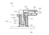
以下、本発明の実施の形態を説明する。図1ないし図4は本発明の一対のシールドコネクタの第1の実施形態を示す。これらの一対のシールドコネクタは、第1部材300に実装されることになる第1コネクタ100と、第2部材400へ接続されることになると共に上記第1コネクタ100に嵌合することになる第2コネクタ200とを備えている。この実施形態では上記第1部材300はプリント配線板であり、上記第1コネクタ100は上記第1部材300に表面実装されるが、本発明の第1部材はプリント配線板に限定解釈されることはなく、導体を備えた物品であればよい。また本発明の第1コネクタの第1部材への実装形態も表面実装に限定解釈されることはなく、例えばディップなどにより実装されてもよい。さらに、この実施形態では上記第2部材400は、内部導体を内部絶縁被覆で覆ってなる内部電線と、この内部電線を覆う外部導体と、この外部導体を覆う外部絶縁被覆とを備えたシールドケーブルであり、上記第2コネクタ200は上記第2部材400に接続される。しかし、本発明の第2部材はシールドケーブルに限定解釈されることはなく、例えば内部導体を内部絶縁被覆で覆ってなる通常の電線のような非シールドケーブルなどであってもよいし、上記シールドケーブルと上記非シールドケーブルとが混在してもよく、またFFC(フレキシブル・フラット・ケーブル)などであってもよい。さらに上記第2コネクタ200の第2部材400への接続形態はハンダ付けであるが、本発明の第2コネクタの第2部材への接続形態は、ハンダ付けに限定解釈されることはなく、例えば圧着接続、圧接接続などによってもよい。また、この実施形態の一対のシールドコネクタは複数の極を有するが、単極であってもよい。
Embodiments of the present invention will be described below. 1 to 4 show a first embodiment of a pair of shielded connectors according to the present invention. The pair of shielded connectors are connected to the
上記第1コネクタ100は、第1ハウジング110と、上記第1ハウジング110に設けられた第1シェル120と、上記第1ハウジング110に設けられた第1コンタクト130とを備えている。以下、部材又は部分に対して嵌合側又は反嵌合側というときは、その部材又は部分が第1コネクタ100に設けられているときは当該第1コネクタ100の嵌合側又は反嵌合側のことであり、その部材又は部分が第2コネクタ200に設けられているときは当該第2コネクタ200の嵌合側又は反嵌合側のことである。嵌合側とは相手側のコネクタに嵌合される側のことであり、反嵌合側とは、この嵌合側と反対側のことである。また、上記第1コネクタ100と上記第2コネクタ200とは、それぞれのコネクタの嵌合側同士を対向させて接近させることで嵌合し、さらに離間させることで離脱するが、この接近又は離脱させる方向を嵌合離脱方向ということにする。そして、上記嵌合離脱方向に直交する方向を奥行き方向とし、上記嵌合離脱方向及び上記奥行き方向に直交する方向を幅方向とする。この実施形態の場合、図2で説明すれば、この図の上下方向が嵌合離脱方向である。また、図2の左右方向が奥行き方向であり、左側が奥側、右側が手前側である。さらに、図2の紙面に垂直な方向が幅方向である。
The
上記第1ハウジング110は合成樹脂により形成されている。上記第1ハウジング110には、嵌合側の面から内方へ凹む凹部116が形成されている。すなわち、上記第1ハウジング110は、奥行き方向の奥側に配置された奥壁111と、奥行き方向の手前側に配置された手前壁112とを備えている。上記奥壁111及び上記手前壁112は、いずれもその板厚方向からみてほぼ長方形に形成された板状部材であって、いずれも板厚方向が上記奥行き方向にほぼ一致するように配置されている。板厚方向とは、その方向に沿った長さが板厚として特定されることになる方向である。上記第1ハウジング110は、さらに、幅方向に対向する二つの側壁113、114を備えている。上記側壁113、114は、いずれもその板厚方向からみてほぼ長方形に形成された板状部材であって、いずれも板厚方向が上記幅方向にほぼ一致するように配置されている。上記奥壁111、上記手前壁112、及び上記側壁113、114は、嵌合離脱方向からみてほぼ四辺形状になるように端縁同士が接続されている。そして、上記奥壁111、上記手前壁112、及び上記側壁113、114の内方に上記凹部116が形成されている。上記第1ハウジング110の反嵌合側には、板厚方向が上記嵌合離脱方向にほぼ一致する底壁115が配置され、この底壁115の周縁が上記奥壁111、上記手前壁112、及び上記側壁113、114の反嵌合側の端縁に接続されている。この実施形態によって本発明の第1ハウジングの構成が限定解釈されることはなく、第1ハウジングは、ほぼ筒形の周壁を備え、その内方に嵌合側の面から内方へ凹む凹部が形成されておればよい。また、本発明は上記した底壁を設けない実施形態を含んでいる。
The
上記第1シェル120は金属により形成されているが、他の導電性材料により形成してもよい。上記第1シェル120は、上記第1ハウジング110に当該第1ハウジング110の外面を覆うように設けられている。すなわち、上記第1シェル120は、上記奥壁111、上記手前壁112、及び上記側壁113、114の外面を覆っている。上記第1シェル120は筒形に形成されて上記第1ハウジング110に外側に嵌まっている。そして、上記第1シェル120にはバネ片が設けられ、このバネ片が上記第1ハウジング110の凹所に嵌合することで上記第1シェル120が上記第1ハウジング110に係止されている。しかし、上記第1シェルは、例えば、複数の部材に分割してもよい。また、実装形態によっては第1シェルにより底壁を覆ってもよい。さらに、上記第1シェルの上記第1ハウジングへの係止は、例えば圧入、ねじ止め、同時成形又はその他の方法によってもよい。
The
上記第1コンタクト130は、極数の数だけ幅方向に並べられている。上記第1コンタクト130は金属により形成されているが、他の導電性材料により形成してもよい。上記第1コンタクト130は、一端が接触部131として上記凹部116の内部に配置されると共に他端が外部へ接続される接続部132として上記第1ハウジング110に設けられている。上記接触部131は、上記手前壁112に沿って設けられている。上記接続部132は、上記底壁115を貫通して上記第1ハウジング110の反嵌合側へ導出されている。しかし、上記接触部は上記凹部の内部におけるどの部位に設けられていてもよいし、上記接続部の導出位置は第1コネクタの実装形態に応じて適宜定められる。
The
上記第2コネクタ200は、第2ハウジング210と、上記第2ハウジング210に設けられた第2シェル220と、上記第2ハウジング210に設けられた第2コンタクト230とを備えている。この実施形態では、上記第2部材400がほぼ奥行き方向手前側へ引き出されるので、上記第1コネクタ100及び上記第2コネクタ200の低背化、つまり上記第1コネクタ100と上記第2コネクタ200とが嵌合したときの高さを低くすることに寄与しているが、これによって本発明の上記第2コネクタにおける上記第2部材との接続構造が限定解釈されることはない。
The
上記第2ハウジング210は合成樹脂により形成されている。上記第2ハウジング210は、ハウジング本体211と、このハウジング本体211から嵌合側へ突出した凸部212とを備えている。上記ハウジング本体211は、内部に第2部材400の接続部、すなわちシールドケーブルの終端が収容される内部空間が形成されたほぼ箱形に形成されている。上記凸部212は上記凹部116の内部空間にほぼ対応する形状に形成されており、上記凹部116への挿入及び上記凹部116からの抜去が可能となるように構成されている。
The
上記第2シェル220は金属により形成されているが、他の導電性材料により形成してもよい。上記第2シェル220は、上記第2ハウジング210に上記ハウジング本体211の外面を覆うように設けられている。すなわち、上記第2シェル220は、上記ハウジング本体211の上面、側面、及び下面を覆っている。上記第2シェル220は、上記ハウジング本体211の上面及び側面を覆う上側部材と、上記ハウジング本体211の下面及び側面を覆う下側部材とに分割されており、この上側部材と下側部材とが一方に設けられたカシメ孔に他方に設けられたカシメ片をカシめることにより互いに接続されている。しかし、上記第2シェルは、例えば、分割することなく一体的な部材を折り曲げてハウジング本体に取り付けてもよい。また、上記第2シェルの上記ハウジング本体への係止は、例えば上記第1シェルのようなバネ片及び凹所による方法、圧入、ねじ止め、同時成形又はその他の方法によってもよい。
The
上記第2コンタクト230は、極数の数だけ幅方向に並べられている。上記第2コンタクト230は金属により形成されているが、他の導電性材料により形成してもよい。上記第2コンタクト230は、一端が上記第1コンタクト130の上記接触部131に接触することになる接触部231として上記凸部212に配置されると共に他端が外部へ接続される接続部232として上記第2ハウジング210に設けられている。上記接触部131は、上記凸部212の奥行き方向手前の面に沿って設けられている。上記接続部132は、上記ハウジング本体211の内部に配置されており、上記第2部材400の接続部、すなわちシールドケーブルの終端が接続されている。この実施形態では、上記第2部材400がほぼ奥行き方向手前側へ引き出されるので、上記第2コンタクト230が中途部で曲がっており、上記接触部231が嵌合離脱方向に沿って延びると共に上記接続部232がほぼ奥行き方向手前側へ延びているが、これによって本発明の上記第2コンタクトの構造が限定解釈されることはない。しかし、上記接触部は上記凸部におけるどの部位に設けられていてもよいし、上記接続部の形態及び接続部が設けられる部位は第2コネクタの第2部材との接続形態に応じて適宜定められる。
The
上記第2ハウジング210の凸部212は、凸部本体212aと、可撓性を有して上記凸部本体212aに設けられたロックレバー212bとを備えている。上記ロックレバー212bは、上記凸部本体212aの嵌合側の先端から反嵌合側へ延びている。そして、上記ロックレバー212bの反嵌合側の端部は、操作部212baとして上記第2コネクタ200の上記第1コネクタ100への嵌合時に上記第1コネクタ100の上記凹部116から外部に出るように設けられている。この実施形態の場合、上記第2ハウジング210の凸部212は、幅方向の両側にそれぞれ設けられた側部212Aと、幅方向の中央に設けられた中央部212Bとを備えている。そして、上記側部212Aは、上記凹部116の幅方向の両側の部位の形状にそれぞれ対応した形状に形成されている。また、上記中央部212Bは、上記凹部116の幅方向の中央の部位の形状に対応した形状に形成されている。そして、上記中央部212Bが奥行き方向に分割されており、これら二つの部分が嵌合側において一体的に接続されている。この上記中央部212Bの奥行き方向手前側の部分と上記両側の側部212Aとにより上記凸部本体212aが構成され、上記中央部212Bの奥行き方向奥側の部分が上記ロックレバー212bを構成している。しかし、この上記実施形態によって上記凸部における上記凸部本体と上記ロックレバーの構成が限定解釈されることはない。
The
上記ロックレバー212bにおける嵌合側の端部と反嵌合側の端部との間の部位と、上記第1ハウジング110の凹部116を構成する壁における上記第2コネクタ200の上記第1コネクタ100への嵌合時に上記ロックレバー212bの上記部位に対向する部位とにロック機構が設けられている。すなわち、上記ロックレバー212bの上記部位に、上記嵌合時に上記凹部構成壁の上記部位へ向かって突出するロック爪212bbが設けられている。上記ロック爪212bbは上記凸部本体212aから離れる方へ突出している。また、上記凹部を構成する壁の上記部位に、上記嵌合時に上記ロック爪212bbが嵌ることができるロック穴111aが形成されている。この実施形態では、上記中央部212Bにおける奥行き方向奥側の部分が上記ロックレバー212bになっているので、上記ロック穴111aは上記第1ハウジングの奥壁111に設けられている。このロック穴111aは、奥壁111を貫通している。そして、上記凸部212の上記凹部116への挿入にしたがい上記ロックレバー212bが上記凸部本体212aに接近するよう撓んでから復原することで上記ロック爪212bbが上記ロック穴111aに嵌り、上記操作部212baを上記凸部本体212aに接近するよう押して上記ロックレバー212bを撓ませると上記ロック爪212bbが上記ロック穴111aから抜けるように構成している。この実施形態では、上記ロックレバー212bを凸部212の奥行き方向奥側に設けたので上記奥壁111に上記ロック穴111aを設けたが、上記ロックレバーを上記凸部の他の部位に設けたときには、上記凹部を構成する壁のうち上記ロックレバーに対向する壁に上記ロック穴を設けることになる。また、この実施形態とは逆に、上記凹部を構成する壁の上記部位に上記ロックレバーの上記部位へ向かって突出するロック爪を設けると共に上記ロックレバーの上記部位にこのロック爪が嵌ることができるロック穴を形成してもよい。上記ロック穴111aは、奥壁111を貫通しているが、上記ロック穴は、凹部を構成する壁を貫通させずに凹ませるだけで形成してもよい。
The
上記第1コネクタ100には、上記ロック穴111aに連通する空洞部140が設けられており、上記ロックレバー212bの復原時に上記ロックレバー212bが上記奥壁111を叩いたときに生じる叩き音が上記空洞部140で共鳴するように構成している。上記空洞部140は、上記第1ハウジング110の奥壁111の外面と、上記第1シェル120との間に形成されている。しかし、上記空洞部を上記第1ハウジングの内部に形成してもよい。そのときは、上記ロック穴は凹部を構成する壁を貫通させずに凹ませるだけで形成し、このロック穴を上記凹部から遠い側で上記空洞部に連通させることになる。また、上記ロック穴が上記凹部を構成する壁のうち他の壁に設けられたときは、空洞部は他の壁の外面と、上記第1シェル120との間に形成され、又は他の壁の内部に設けられる。
The
次に、上記実施形態の一対のシールドコネクタの作用及び効果を説明する。上記第2コネクタ200を上記第1コネクタ100に嵌合する場合、上記第2コネクタ200の上記凸部212を上記第1コネクタ100の上記凹部116へ挿入すると、上記ロックレバー212bが上記凸部本体212aに接近するよう撓んでから復原することで上記ロック爪212bbが上記ロック穴111aに嵌り、上記第2コンタクト230の上記接触部231が上記第1コンタクト130の上記接触部131に接触する。また、上記第2コネクタ200を上記第1コネクタ100から離間させる場合、上記操作部212baを上記凸部本体212aに接近するよう押して上記ロックレバー212bを撓ませると上記ロック爪212bbが上記ロック穴111aから抜け、上記第2コネクタ200の上記凸部212を上記第1コネクタ100の上記凹部116から抜去することが可能となる。
Next, operations and effects of the pair of shield connectors of the above embodiment will be described. When the
そして、上記第2コネクタ200を上記第1コネクタ100に嵌合する場合、上記ロックレバー212bが上記凸部本体212aに接近するよう撓んでから復原すると、上記ロックレバー212bが上記凹部116を構成する奥壁111を叩く。その場合、上記ロックレバー212b及び上記奥壁111はいずれも合成樹脂により形成されているので、上記ロックレバー212bが上記奥壁111を擦ってから上記奥壁111を叩くまでの間に第2コネクタ200から得られる嵌合フィーリングと、上記ロックレバー212bが上記奥壁111を叩くことで発生する嵌合音とが、上記ロックレバー212b及び上記奥壁111をいずれも金属により形成した場合とは全く異質のものとなる。よって、合成樹脂製ロックレバーと合成樹脂製ハウジングとによる独特の嵌合フィーリング及び嵌合音を得ることができる。
When the
また、上記凹部116の内側において上記ロック爪212bbと上記ロック穴111aとの嵌合と解除とが行われるので、上記第1シェル120及び上記第2シェル220に上記ロック爪212bbと上記ロック穴111aとを嵌合させるための開口を設ける必要がない。そのため、上記第1シェル120及び上記第2シェル220によるシールド機能を高めることが可能となる。その場合、上記引用文献4の上記レセプタクルコネクタのように、ハウジング及びシェルの外側にもう一つのシェルを設ける必要がないのでシールドコネクタのコストの増大及び大型化を防ぐことができる。さらに、上記第2コネクタ200を上記第1コネクタ100に嵌合すると上記ロックレバー212bが上記凹部116に収まるので、上記ロックレバー212bが外力を受けて損傷するおそれがない。
In addition, since the lock claw 212bb and the
上記第1の実施形態では、上記第1コネクタ100に、上記ロック穴111aに連通する空洞部140を設けた。このようにすれば、上記第2コネクタ200を上記第1コネクタ100に嵌合する場合、上記ロックレバー212bが上記凸部本体212aに接近するよう撓んでから復原すると、上記ロックレバー212bが上記凹部116を構成する奥壁111を叩くが、この叩き音が上記空洞部140で共鳴するので、音が増幅される。そのため、両コネクタの嵌合完了の検出がより確実に行われ、半嵌合による接続不良の発生防止、コネクタの嵌合方向への強引な押し込みによるコネクタの損傷防止などが一層確実に行われる。
In the first embodiment, the
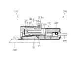
図5及び図6は、本発明の一対のシールドコネクタの第2の実施形態を示す。この実施形態には上記第1の実施形態及びその変形例の構成をそのまま引用し、第2の実施形態において上記第1の実施形態の構成と異なる構成について追加的に説明する。上記第1の実施形態の場合、上記第1コネクタ100は上記第1部材300に、上記底壁115が上記第1部材300の表面に対向するように、つまり上記第1コネクタ100及び上記第2コネクタ200の上記嵌合離脱方向が上記第1部材300の表面にほぼ直交するように実装された。これに対し、上記第2の実施形態の場合、上記第1コネクタ100は上記第1部材300に、上記手前壁112が上記第1部材300の表面に対向するように、つまり上記第1コネクタ100及び上記第2コネクタ200の上記嵌合離脱方向が上記第1部材300の表面にほぼ平行になるように実装される。そのため、上記第1の実施形態では、上記第2部材400がほぼ奥行き方向手前側へ引き出されるので、上記第2コンタクト230が中途部で曲がっていたが、上記第2の実施形態では、上記第2部材400がほぼ嵌合離脱方向へ引き出されるので、上記第2コンタクト230はほぼ真っ直ぐに形成されている。第2の実施形態におけるその他の構成、作用及び効果は、上記第1の実施形態と同様であるから説明を省略する。
5 and 6 show a second embodiment of a pair of shielded connectors according to the present invention. In this embodiment, the configurations of the first embodiment and the modifications thereof are cited as they are, and a configuration different from the configuration of the first embodiment in the second embodiment will be additionally described. In the case of the first embodiment, the
本発明の一対のシールドコネクタは、以上の実施形態の一対のシールドコネクタの特徴を組み合わせた実施形態を全て含む。 The pair of shield connectors of the present invention includes all embodiments in which the features of the pair of shield connectors of the above embodiments are combined.
100 第1コネクタ
110 第1ハウジング
111 奥壁
111a ロック穴
116 凹部
120 第1シェル
130 第1コンタクト
131 接触部
132 接続部
200 第2コネクタ
210 第2ハウジング
211 ハウジング本体
212 凸部
212a 凸部本体
212b ロックレバー
212ba 操作部
212bb ロック爪
220 第2シェル
230 第2コンタクト
231 接触部
232 接続部
DESCRIPTION OF
Claims (1)
上記第1コネクタは、合成樹脂により形成されて嵌合側の面から内方へ凹む凹部が形成された第1ハウジングと、導電性材料により形成されて上記第1ハウジングに当該第1ハウジングの外面を覆うように設けられた第1シェルと、導電性材料により形成されて上記第1ハウジングに設けられ、一端が接触部として上記凹部の内部に配置されると共に他端が外部へ接続される接続部として上記第1ハウジングに配置された第1コンタクトとを備え、
上記第2コネクタは、合成樹脂により形成されてハウジング本体と当該ハウジング本体から嵌合側へ突出して上記凹部への挿入及び上記凹部からの抜去が可能な凸部とを有する第2ハウジングと、導電性材料により形成されて上記第2ハウジングに上記ハウジング本体の外面を覆うように設けられた第2シェルと、導電性材料により形成されて上記第2ハウジングに設けられ、一端が上記第1コンタクトの上記接触部に接触することになる接触部として上記凸部に配置されると共に他端が外部へ接続される接続部として上記第2ハウジングに配置された第2コンタクトとを備え、
上記第2ハウジングの凸部は、凸部本体と、可撓性を有して上記凸部本体の嵌合側の先端から反嵌合側へ延びて、反嵌合側の端部が操作部として上記第2コネクタの上記第1コネクタへの嵌合時に上記第1コネクタの上記凹部から外部へ出るように設けられたロックレバーとを備え、
上記ロックレバーにおける嵌合側の端部と反嵌合側の端部との間の部位と、上記第1ハウジングの凹部を構成する壁における上記第2コネクタの上記第1コネクタへの嵌合時に上記ロックレバーの上記部位に対向する部位とのうち、一方の部位には他方の部位へ向かって突出するロック爪が設けられ、他方の部位には上記ロック爪が嵌ることができるロック穴が形成されており、
上記第1コネクタには、上記ロック穴に連通する空洞部が設けられており、
上記凸部の上記凹部への挿入にしたがい上記ロックレバーが上記凸部本体に接近するよう撓んでから復原することで上記ロック爪が上記ロック穴に嵌り、上記操作部を上記凸部本体に接近するよう押して上記ロックレバーを撓ませると上記ロック爪が上記ロック穴から抜けるように構成すると共に、上記ロックレバーの復原時に上記ロックレバーが上記奥壁を叩いたときに生じる叩き音が上記空洞部で共鳴するように構成した一対のシールドコネクタ。 A first connector and a second connector to be fitted to the first connector;
The first connector is formed of a synthetic resin and has a first housing formed with a recess recessed inward from the surface on the fitting side. The first connector is formed of a conductive material and is formed on the first housing with the outer surface of the first housing. A first shell provided so as to cover the surface, a connection formed by a conductive material and provided in the first housing, with one end disposed as a contact portion inside the recess and the other end connected to the outside A first contact disposed in the first housing as a part,
The second connector is formed of a synthetic resin and has a housing main body, a second housing that protrudes from the housing main body toward the fitting side, and can be inserted into the concave portion and removed from the concave portion, and conductive A second shell formed of a conductive material so as to cover the outer surface of the housing body, and a second shell formed of a conductive material and provided on the second housing. A second contact disposed on the second housing as a connection portion disposed on the convex portion as a contact portion to be in contact with the contact portion and connected to the outside at the other end;
The convex part of the second housing has a convex part main body and has flexibility and extends from the tip of the convex part main body on the mating side to the non-fitting side. A lock lever provided so as to come out from the concave portion of the first connector when the second connector is fitted to the first connector,
At the time of fitting the second connector to the first connector in the portion of the lock lever between the fitting end and the non-fitting end and the wall constituting the recess of the first housing Of the part of the lock lever facing the part, a lock claw protruding toward the other part is provided at one part, and a lock hole into which the lock claw can be fitted is formed at the other part. Has been
The first connector is provided with a cavity communicating with the lock hole,
The lock lever is bent so as to approach the convex body as the convex portion is inserted into the concave portion, and then restored so that the lock claw fits into the lock hole, and the operating portion approaches the convex body. When the lock lever is bent so as to be bent, the lock claw is pulled out from the lock hole, and when the lock lever is restored, a hitting sound generated when the lock lever hits the back wall is generated. A pair of shield connectors configured to resonate with each other.
Priority Applications (1)
| Application Number | Priority Date | Filing Date | Title |
|---|---|---|---|
| JP2009065322A JP5306003B2 (en) | 2009-03-17 | 2009-03-17 | Pair of shielded connectors |
Applications Claiming Priority (1)
| Application Number | Priority Date | Filing Date | Title |
|---|---|---|---|
| JP2009065322A JP5306003B2 (en) | 2009-03-17 | 2009-03-17 | Pair of shielded connectors |
Publications (2)
| Publication Number | Publication Date |
|---|---|
| JP2010218924A JP2010218924A (en) | 2010-09-30 |
| JP5306003B2 true JP5306003B2 (en) | 2013-10-02 |
Family
ID=42977525
Family Applications (1)
| Application Number | Title | Priority Date | Filing Date |
|---|---|---|---|
| JP2009065322A Active JP5306003B2 (en) | 2009-03-17 | 2009-03-17 | Pair of shielded connectors |
Country Status (1)
| Country | Link |
|---|---|
| JP (1) | JP5306003B2 (en) |
Family Cites Families (2)
| Publication number | Priority date | Publication date | Assignee | Title |
|---|---|---|---|---|
| JP2512523Y2 (en) * | 1991-05-17 | 1996-10-02 | 日本航空電子工業株式会社 | connector |
| JPH0648773Y2 (en) * | 1991-06-07 | 1994-12-12 | 日本航空電子工業株式会社 | Receptacle connector and plug connector for branching |
-
2009
- 2009-03-17 JP JP2009065322A patent/JP5306003B2/en active Active
Also Published As
| Publication number | Publication date |
|---|---|
| JP2010218924A (en) | 2010-09-30 |
Similar Documents
| Publication | Publication Date | Title |
|---|---|---|
| US9762009B2 (en) | Plug connector insertable in two orientations and having a metallic shield plate with arms with hook structures | |
| CN100524957C (en) | Plug connector | |
| US9525223B2 (en) | Flippable electrical connector | |
| JP3142836U (en) | Plug connector with mating protection and alignment means | |
| US7771232B2 (en) | Electrical connector having a shell with a portion retained in an insulative housing | |
| US8007317B2 (en) | Cable connector assembly with an improved shell | |
| US8070528B2 (en) | Electrical connector having improved terminals | |
| US8070517B2 (en) | Electrical connector having an improved spring member for abutting against a metal plate | |
| JP6097072B2 (en) | connector | |
| US7134900B2 (en) | Electrical connector assembly with multi-function latching member | |
| US8905781B2 (en) | Coaxial electrical connector having retaining arms and coaxial electrical connector assembly having the same | |
| US8894433B2 (en) | Electrical connector assembly with enhanced blind mating features | |
| US20080038951A1 (en) | Upright electrical connector | |
| JP2010218712A (en) | Connector | |
| JP5284150B2 (en) | A pair of connectors with locking mechanism | |
| US9583873B2 (en) | Electrical connector having detecting structure | |
| EP2827459B1 (en) | Connector | |
| JP2007180008A (en) | Connector plug | |
| US20150044899A1 (en) | Electrical connector with additional exterior shell | |
| US6808427B1 (en) | Electrical connector with anti-mismating device | |
| JP2016184505A (en) | Electric connector for board connection and electric connector device for board connection | |
| TW201334295A (en) | Connector | |
| US7726986B2 (en) | Electrical connector having metal shell equipped with a pair of outwardly protruding resilent arms offset from each other | |
| JP5306003B2 (en) | Pair of shielded connectors | |
| JP4523062B1 (en) | Low profile electrical connector |
Legal Events
| Date | Code | Title | Description |
|---|---|---|---|
| A621 | Written request for application examination |
Free format text: JAPANESE INTERMEDIATE CODE: A621 Effective date: 20120206 |
|
| A131 | Notification of reasons for refusal |
Free format text: JAPANESE INTERMEDIATE CODE: A131 Effective date: 20130305 |
|
| A521 | Request for written amendment filed |
Free format text: JAPANESE INTERMEDIATE CODE: A523 Effective date: 20130430 |
|
| TRDD | Decision of grant or rejection written | ||
| A01 | Written decision to grant a patent or to grant a registration (utility model) |
Free format text: JAPANESE INTERMEDIATE CODE: A01 Effective date: 20130611 |
|
| A61 | First payment of annual fees (during grant procedure) |
Free format text: JAPANESE INTERMEDIATE CODE: A61 Effective date: 20130625 |
|
| R150 | Certificate of patent or registration of utility model |
Free format text: JAPANESE INTERMEDIATE CODE: R150 Ref document number: 5306003 Country of ref document: JP Free format text: JAPANESE INTERMEDIATE CODE: R150 |
|
| R250 | Receipt of annual fees |
Free format text: JAPANESE INTERMEDIATE CODE: R250 |
|
| R250 | Receipt of annual fees |
Free format text: JAPANESE INTERMEDIATE CODE: R250 |
|
| R250 | Receipt of annual fees |
Free format text: JAPANESE INTERMEDIATE CODE: R250 |
|
| R250 | Receipt of annual fees |
Free format text: JAPANESE INTERMEDIATE CODE: R250 |
|
| R250 | Receipt of annual fees |
Free format text: JAPANESE INTERMEDIATE CODE: R250 |
|
| R250 | Receipt of annual fees |
Free format text: JAPANESE INTERMEDIATE CODE: R250 |
|
| R250 | Receipt of annual fees |
Free format text: JAPANESE INTERMEDIATE CODE: R250 |
|
| RD04 | Notification of resignation of power of attorney |
Free format text: JAPANESE INTERMEDIATE CODE: R3D04 |
|
| R250 | Receipt of annual fees |
Free format text: JAPANESE INTERMEDIATE CODE: R250 |
|
| R250 | Receipt of annual fees |
Free format text: JAPANESE INTERMEDIATE CODE: R250 |
|
| R250 | Receipt of annual fees |
Free format text: JAPANESE INTERMEDIATE CODE: R250 |