JP5275896B2 - Floor slabs and buildings - Google Patents
Floor slabs and buildings Download PDFInfo
- Publication number
- JP5275896B2 JP5275896B2 JP2009118841A JP2009118841A JP5275896B2 JP 5275896 B2 JP5275896 B2 JP 5275896B2 JP 2009118841 A JP2009118841 A JP 2009118841A JP 2009118841 A JP2009118841 A JP 2009118841A JP 5275896 B2 JP5275896 B2 JP 5275896B2
- Authority
- JP
- Japan
- Prior art keywords
- floor slab
- core portion
- plate
- lower plate
- upper plate
- Prior art date
- Legal status (The legal status is an assumption and is not a legal conclusion. Google has not performed a legal analysis and makes no representation as to the accuracy of the status listed.)
- Expired - Fee Related
Links
- 239000002184 metal Substances 0.000 claims abstract description 19
- 239000011381 foam concrete Substances 0.000 claims description 35
- 230000002265 prevention Effects 0.000 claims description 7
- 229920005989 resin Polymers 0.000 claims description 7
- 239000011347 resin Substances 0.000 claims description 7
- 238000000034 method Methods 0.000 description 25
- 238000012986 modification Methods 0.000 description 20
- 230000004048 modification Effects 0.000 description 20
- 239000000463 material Substances 0.000 description 18
- 238000004519 manufacturing process Methods 0.000 description 17
- 239000000853 adhesive Substances 0.000 description 16
- 238000005192 partition Methods 0.000 description 16
- 238000005304 joining Methods 0.000 description 13
- 230000001070 adhesive effect Effects 0.000 description 12
- 238000005452 bending Methods 0.000 description 12
- 239000004567 concrete Substances 0.000 description 10
- 230000000694 effects Effects 0.000 description 7
- 239000011178 precast concrete Substances 0.000 description 7
- 230000002093 peripheral effect Effects 0.000 description 6
- 229910000831 Steel Inorganic materials 0.000 description 5
- 239000011150 reinforced concrete Substances 0.000 description 5
- 230000003014 reinforcing effect Effects 0.000 description 5
- 239000010959 steel Substances 0.000 description 5
- NJPPVKZQTLUDBO-UHFFFAOYSA-N novaluron Chemical compound C1=C(Cl)C(OC(F)(F)C(OC(F)(F)F)F)=CC=C1NC(=O)NC(=O)C1=C(F)C=CC=C1F NJPPVKZQTLUDBO-UHFFFAOYSA-N 0.000 description 4
- 230000010354 integration Effects 0.000 description 3
- 239000002390 adhesive tape Substances 0.000 description 2
- 230000015572 biosynthetic process Effects 0.000 description 2
- 239000003822 epoxy resin Substances 0.000 description 2
- 238000002474 experimental method Methods 0.000 description 2
- 238000009434 installation Methods 0.000 description 2
- 239000007769 metal material Substances 0.000 description 2
- 239000000203 mixture Substances 0.000 description 2
- 239000004570 mortar (masonry) Substances 0.000 description 2
- 229920002647 polyamide Polymers 0.000 description 2
- 229920000647 polyepoxide Polymers 0.000 description 2
- 229920002050 silicone resin Polymers 0.000 description 2
- 229910000975 Carbon steel Inorganic materials 0.000 description 1
- 239000004952 Polyamide Substances 0.000 description 1
- 239000011248 coating agent Substances 0.000 description 1
- 238000000576 coating method Methods 0.000 description 1
- 230000006835 compression Effects 0.000 description 1
- 238000007906 compression Methods 0.000 description 1
- 238000013461 design Methods 0.000 description 1
- 238000010586 diagram Methods 0.000 description 1
- 238000006073 displacement reaction Methods 0.000 description 1
- 238000004049 embossing Methods 0.000 description 1
- 230000005484 gravity Effects 0.000 description 1
- 238000009413 insulation Methods 0.000 description 1
- 238000013001 point bending Methods 0.000 description 1
- 238000007789 sealing Methods 0.000 description 1
- 229910001220 stainless steel Inorganic materials 0.000 description 1
- 239000010935 stainless steel Substances 0.000 description 1
- 238000012360 testing method Methods 0.000 description 1
- 239000013585 weight reducing agent Substances 0.000 description 1
- 238000003466 welding Methods 0.000 description 1
Images


Landscapes
- Building Environments (AREA)
Abstract
Description
本発明は、サンドイッチ構造の床版、及びこの床版を有する建築物に関する。 The present invention relates to a sandwich slab and a building having the slab.
建築物に用いられる床版は、鉄筋コンクリートによって形成されることが多い。鉄筋コンクリート製の床版は、所定の面外剛性を得るために、ある程度の厚さを必要とする。よって、重量が重くなる傾向にある。このため、この床版を支持する柱や梁等の部材の構造断面を大きくしなければならない。また、鉄筋コンクリートによって形成されたプレキャスト製の床版は重量が重いので、搬送時や設置時における取り扱いが不便となる。 Floor slabs used in buildings are often formed from reinforced concrete. A reinforced concrete floor slab requires a certain thickness in order to obtain a predetermined out-of-plane rigidity. Therefore, the weight tends to increase. For this reason, the structural cross section of members such as columns and beams that support the slab must be enlarged. Moreover, since the precast floor slab formed of reinforced concrete is heavy, handling at the time of conveyance and installation becomes inconvenient.
この問題を解決するために、軽量化されたコンクリート床版が提案されている。例えば図29に示すように、特許文献1のプレキャストコンクリート床板300では、このプレキャストコンクリート床板300の上面と下面とを構成する、コンクリート床板302と金属製薄板304とが、周辺枠フレーム306に取り付けられている。また、コンクリート床板302、金属製薄板304、及び周辺枠フレーム306によって形成される密閉空間に発泡樹脂308が充填されている。すなわち、プレキャストコンクリート床板300のコア部が、コンクリート床板302と発泡樹脂308とによって構成されている。
In order to solve this problem, a lightweight concrete slab has been proposed. For example, as shown in FIG. 29, in the precast
よって、プレキャストコンクリート床板300の一部に発泡樹脂308を用いることによりプレキャストコンクリート床板300の軽量化を図り、また、金属製薄板304に膜張力を導入することによりプレキャストコンクリート床板300の面外剛性を向上させることができる。
しかし、コンクリート床板302の部分の重量は従来の鉄筋コンクリート製の床版と変わりなく、更なる軽量化が望まれる。
Accordingly, the
However, the weight of the portion of the
本発明は係る事実を考慮し、所定の面外剛性を有する軽量の床版、及びこの床版を有する建築物を提供することを課題とする。 In view of such facts, an object of the present invention is to provide a lightweight floor slab having predetermined out-of-plane rigidity and a building having the floor slab.
第1態様の発明は、金属製の下板と、前記下板の上方に配置された金属製の上板と、前記下板と前記上板との間に形成され前記下板及び前記上板と一体となるコア部と、を有し、前記下板及び前記上板の少なくとも一方は、前記コア部に対向する面積が前記コア部の下面又は上面の面積よりも小さい床版である。 The first aspect of the invention includes a metal lower plate, a metal upper plate disposed above the lower plate, and the lower plate and the upper plate formed between the lower plate and the upper plate. And at least one of the lower plate and the upper plate is a floor slab whose area facing the core portion is smaller than the area of the lower surface or the upper surface of the core portion.
第1態様の発明では、金属製の下板と、この下板の上方に配置された金属製の上板との間に、コア部が形成されている。コア部と、下板及び上板とは一体となっている。
そして、下板及び上板の少なくとも一方は、コア部に対向する面積がコア部の下面又は上面の面積よりも小さい。すなわち、下板のコア部に対向する面積がコア部の下面の面積よりも小さい、上板のコア部に対向する面積がコア部の上面の面積よりも小さい、又は下板のコア部に対向する面積がコア部の下面の面積よりも小さく且つ上板のコア部に対向する面積がコア部の上面の面積よりも小さい。
In the first aspect of the invention, the core portion is formed between the metal lower plate and the metal upper plate disposed above the lower plate. The core portion is integrated with the lower plate and the upper plate.
At least one of the lower plate and the upper plate has an area facing the core portion that is smaller than the area of the lower surface or the upper surface of the core portion. That is, the area facing the core portion of the lower plate is smaller than the area of the lower surface of the core portion, the area facing the core portion of the upper plate is smaller than the area of the upper surface of the core portion, or opposed to the core portion of the lower plate And the area facing the core part of the upper plate is smaller than the area of the upper surface of the core part.
よって、下板、コア部、及び上板が一体となる床版は、サンドイッチ構造を構成する。このサンドイッチ構造の床版に曲げ荷重が作用すると、床版の上部には圧縮力が発生し、床版の下部には引張力が発生する。そして、これらの力に対して主に上板及び下板が抵抗することにより、所定の面外剛性を得ることができる。 Therefore, the floor slab in which the lower plate, the core portion, and the upper plate are integrated constitutes a sandwich structure. When a bending load is applied to the sandwich structure floor slab, a compressive force is generated at the upper part of the floor slab, and a tensile force is generated at the lower part of the floor slab. A predetermined out-of-plane rigidity can be obtained by mainly resisting the upper plate and the lower plate against these forces.
また、サンドイッチ構造により、下板及び上板からなる断面2次モーメントは、下板と上板との単体の断面2次モーメントを単純に足し合わせた値よりも遥かに大きくなる。これによって効率よく大きな面外剛性を得ることができる。
そして、大きな面外剛性を確保することによって床振動を低減することが可能になり、これにより居住性を向上させることができる。
Further, due to the sandwich structure, the secondary moment of section composed of the lower plate and the upper plate is much larger than the value obtained by simply adding the single sectional secondary moments of the lower plate and the upper plate. Thereby, large out-of-plane rigidity can be obtained efficiently.
And it becomes possible to reduce floor vibration by ensuring large out-of-plane rigidity, and thereby, comfort can be improved.
また、金属製の上板及び下板は強度及び剛性が大きいので、上板及び下板を薄くすることが可能である。これにより、床版を軽くすることができる。
また、床版に作用する鉛直荷重に対して金属製の下板が存在するので、一般の鉄筋コンクリート系床版で問題となっているクリープ変形が発生しない。
Further, since the upper and lower plates made of metal have high strength and rigidity, the upper and lower plates can be made thin. Thereby, a floor slab can be lightened.
In addition, since a metal lower plate is present for a vertical load acting on the floor slab, creep deformation which is a problem in a general reinforced concrete floor slab does not occur.
また、形成されたコア部に下板及び上板を固定して床版を製造する場合、下板及び上板の少なくとも一方は、コア部に対向する面積がコア部の下面又は上面の面積よりも小さい大きさでよいので、固定作業の手間を低減することができ、また、下板及び上板の少なくとも一方の材料費を低減することができる。 Further, when a floor slab is manufactured by fixing the lower plate and the upper plate to the formed core portion, at least one of the lower plate and the upper plate has an area facing the core portion that is smaller than the area of the lower surface or the upper surface of the core portion. Therefore, the labor of fixing work can be reduced, and the material cost of at least one of the lower plate and the upper plate can be reduced.
また、オートクレーブ養生を施すことにより完全に硬化する材料を用いてコア部を形成し、このコア部の形成と共に(材料が硬化するときに)、下板、コア部、及び上板を一体にして床版を製造する場合、オートクレーブ養生時において、下板や上板が設けられていない部分を介して蒸気を流通させることができる。すなわち、コア部に下板及び上板が設けられた状態で、オートクレーブ養生を効果的に行うことができる。 Moreover, a core part is formed using the material which hardens | cures completely by performing an autoclave curing, A lower board, a core part, and an upper board are united with this core part formation (when material hardens | cures). In the case of producing a floor slab, steam can be circulated through a portion where no lower plate or upper plate is provided during autoclave curing. That is, autoclave curing can be effectively performed in a state where the lower plate and the upper plate are provided in the core portion.
第2態様の発明は、第1態様の床版において、前記下板及び前記上板の少なくとも一方は、前記コア部の全長に渡って帯状に配置されている。 According to a second aspect of the invention, in the floor slab of the first aspect, at least one of the lower plate and the upper plate is disposed in a strip shape over the entire length of the core portion.
第2態様の発明では、下板及び上板の少なくとも一方が、コア部の全長に渡って帯状に配置されているので、コア部の全長に渡って下板及び上板に面外剛性を負担させることができる。 In the invention of the second aspect , since at least one of the lower plate and the upper plate is disposed in a strip shape over the entire length of the core portion, the out-of-plane rigidity is imposed on the lower plate and the upper plate over the entire length of the core portion. Can be made.
第3態様の発明は、第1態様の床版において、前記下板は、前記コア部に対向する面積が前記コア部の下面の面積と等しく、前記上板は、前記コア部に対向する面積が前記コア部の上面の面積よりも小さい。 According to a third aspect of the invention, in the floor slab of the first aspect , the lower plate has an area facing the core portion equal to an area of the lower surface of the core portion, and the upper plate is an area facing the core portion. Is smaller than the area of the upper surface of the core portion.
第3態様の発明では、下板は、コア部に対向する面積がコア部の下面の面積と等しくなっているので、材料を打設してコア部を形成するための型枠として下板を兼用することができる。 In the invention of the third aspect , since the lower plate has an area facing the core portion equal to the area of the lower surface of the core portion, the lower plate is used as a mold for forming the core portion by placing material. Can also be used.
また、上板が配置されていない部分は開口部となるので、コア部を形成する材料をこの開口部から投入することができる。すなわち、打設用に材料を投入する開口部を別途設ける必要がなくなる。 Further, since the portion where the upper plate is not disposed becomes an opening, the material for forming the core portion can be introduced from this opening. That is, it is not necessary to separately provide an opening for introducing a material for placement.
第4態様の発明は、第1〜第3態様の何れか1態様の床版において、前記下板は下方に凸の形状となっている。 According to a fourth aspect of the invention, in the floor slab of any one of the first to third aspects, the lower plate has a downwardly convex shape.
第4態様の発明では、床版に鉛直荷重が作用すると、下方に凸の形状となる下板には引張力(下板の両端を斜め上方へ引き上げる力)が発生する。そして、下板の引張力によって床版全体を上方向に押し上げる効果が生じ、床版に生じる曲げモーメントが軽減される。これにより、床版内部に発生する応力が小さくなるので、コア部に必要とされるせん断強度や、上板に必要とされる座屈強度を小さくすることができる。
また、下方に凸の形状となる下板の引張剛性が床版の面外剛性に大きく寄与するので、面外剛性を効果的に向上させることができる。
In the fourth aspect of the invention, when a vertical load is applied to the floor slab, a tensile force (a force for pulling up both ends of the lower plate obliquely upward) is generated on the lower plate that is convex downward. And the effect which pushes up the whole floor slab upward by the tensile force of a lower board arises, and the bending moment which arises in a floor slab is reduced. Thereby, since the stress which generate | occur | produces inside a floor slab becomes small, the shear strength required for a core part and the buckling strength required for an upper board can be made small.
Further, since the tensile rigidity of the lower plate having a downwardly convex shape greatly contributes to the out-of-plane rigidity of the floor slab, the out-of-plane rigidity can be effectively improved.
第5態様の発明は、第1〜第4態様の何れか1態様の床版において、前記上板の下面には該上板の座屈を防ぐ座屈防止手段が設けられている。 According to a fifth aspect of the invention, in the floor slab of any one of the first to fourth aspects, buckling prevention means for preventing buckling of the upper plate is provided on the lower surface of the upper plate.
第5態様の発明では、上板の座屈を防ぐ座屈防止手段が上板の下面に設けられている。
よって、上板及びコア部からなる床版の上部に圧縮力が発生したときに、上板が圧縮座屈するのを防ぐことができる。これにより、板厚の薄い上板でも圧縮力を負担することができるため、床版としての所定の面外剛性を得ることができる。
In the fifth aspect of the invention, buckling prevention means for preventing buckling of the upper plate is provided on the lower surface of the upper plate.
Therefore, when a compressive force is generated in the upper part of the floor slab composed of the upper plate and the core portion, the upper plate can be prevented from being compressed and buckled. Thereby, since a compressive force can be borne even with an upper plate having a thin plate thickness, a predetermined out-of-plane rigidity as a floor slab can be obtained.
第6態様の発明は、第1〜第5態様の何れか1態様の床版において、前記コア部は、軽量気泡コンクリート、軽量コンクリート、又は発泡性樹脂によって形成されている。 According to a sixth aspect of the invention, in the floor slab of any one of the first to fifth aspects, the core portion is formed of lightweight cellular concrete, lightweight concrete, or foamable resin.
第6態様の発明では、コア部を、軽量気泡コンクリート、軽量コンクリート、又は発泡性樹脂によって形成することにより、コア部に必要とされるせん断剛性を確保することが可能となる。
よって、床版の軽量化を図ると共に、所定の面外剛性を得ることができる。
In the sixth aspect of the invention, the shear rigidity required for the core part can be ensured by forming the core part from lightweight cellular concrete, lightweight concrete, or foamable resin.
Therefore, the floor slab can be reduced in weight and a predetermined out-of-plane rigidity can be obtained.
第7態様の発明は、第1〜第6態様の何れか1態様の床版を有する建築物である。 The invention of the seventh aspect is a building having the floor slab of any one of the first to sixth aspects .
第7態様の発明では、所定の面外剛性を有する軽量の床版を有する建築物を構築することができる。 In the invention of the seventh aspect , it is possible to construct a building having a lightweight floor slab having a predetermined out-of-plane rigidity.
本発明は上記構成としたので、所定の面外剛性を有する軽量の床版、及びこの床版を有する建築物を提供することができる。 Since this invention set it as the said structure, the lightweight floor slab which has predetermined | prescribed out-plane rigidity, and the building which has this floor slab can be provided.
図を参照しながら、本発明の床版及び建築物を説明する。
まず、本発明の第1の実施形態について説明する。
The floor slab and building of the present invention will be described with reference to the drawings.
First, a first embodiment of the present invention will be described.
図1の斜視図に示すように、床版10は、対向して配置された2つのH型鋼12、14の上に架設され、建築物の床構造を構成する一方向スラブとして使用される。
床版10は、金属製の下板16、コア部18、及び金属製の上板20を有する。コア部18は、下板16と、下板16の上方に配置された上板20との間に、軽量気泡コンクリートUによって形成されている。図1の状態で、下板16、コア部18、及び上板20は一体となっている。下板16及び上板20には、普通鋼やステンレス鋼を用いるのが好ましい。
As shown in the perspective view of FIG. 1, the
The
また、床版10の上方から床版10の上面を見た平面図である図2(a)、床版10の下方から床版10の下面を見た平面図である図2(b)、及び図2(a)のA−A矢視図である図2(c)に示すように、下板16及び上板20は、床版10の支持スパン方向22のコア部18全長に渡り、支持スパン方向22と直交する水平方向24(以下、「幅方向24」とする)における、コア部18の下面及び上面の両端に帯状に配置されている。
FIG. 2A is a plan view of the top surface of the
すなわち、コア部18に対向する2つの下板16の面積の合計は、コア部18の下面の面積よりも小さくなっており、また、コア部18に対向する2つの上板20の面積の合計は、コア部18の上面の面積よりも小さくなっている。
That is, the total area of the two
なお、図2(c)に示すように、第1の実施形態において、下板16と上板20との間にコア部18が形成されているとは、下板16の真上、及び上板20の真下のみにコア部18が形成されているのではなく、下板16を有する下層と、上板20を有する上層との間の全域にコア部18が形成されていることを意味する。
As shown in FIG. 2C, in the first embodiment, the
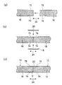
床版10は、例えば、図3(a)〜(c)に示す床版の製造方法によって製造することができる。
まず、図4の斜視図、及び図4のB−B矢視図である図3(a)に示すように、所定の距離を離して台座26を設置する。そして、台座26上に下板16を配置する(下板配置工程)。下板16は、コア部18が形成される空間Wへ軽量気泡コンクリートUを投入した際にこの位置から動かないように台座26上に保持されると共に、軽量気泡コンクリートUが完全に硬化してコア部18が形成された後に台座26から取り外せる方法を用いて台座26に仮固定をしておく。例えば、両面接着テープを用いて、台座26に下板16を仮固定してもよい。
The
First, as shown in FIG. 3A which is a perspective view of FIG. 4 and a BB arrow view of FIG. 4, the
所定の距離を離して設置された台座26の間には、板状の底型枠28が着脱可能に設置されており、底型枠28を設置した状態で、下板16の下面と、底型枠28の上面とが面一となっている。
A plate-
次に、空間Wの周囲を囲むように側型枠30、32を配置する。側型枠30は、空間Wの幅方向24端面に対向するように配置し、側型枠32は、空間Wの支持スパン方向22端面に対向するように配置する。
このように配置した状態で、側型枠30、32の下部は、台座26に着脱可能に固定される。
Next, the
With the arrangement as described above, the lower portions of the
次に、向かい合って配置された側型枠30上に、角柱状の上板仮固定部材34を架設する。上板仮固定部材34は、支持スパン方向22に等間隔に複数配置され、ボルト36によって側型枠30に固定されている。
Next, a prismatic upper plate temporary fixing
次に、上板仮固定部材34の下面に上板20を配置する(上板配置工程)。すなわち、下板16の上方にこの下板16と離して上板20を配置する。
上板20は、空間Wへ軽量気泡コンクリートUを投入した際に、この位置から動かないように上板仮固定部材34の下面に保持されると共に、軽量気泡コンクリートUが半硬化状態のコア部18となった後に上板仮固定部材34を取り外せる方法を用いて上板仮固定部材34に仮固定をしておく。例えば、両面接着テープを用いて、上板仮固定部材34に上板20を仮固定してもよい。
Next, the
The
次に、図3(b)に示すように、底型枠28、下板16、側型枠30、32、及び上板20によって囲まれた空間Wへ、軽量気泡コンクリートUを投入し、空間Wの全域に軽量気泡コンクリートUを行き渡らせる。
Next, as shown in FIG. 3 (b), lightweight lightweight concrete U is poured into a space W surrounded by the
次に、図3(c)に示すように、軽量気泡コンクリートUが半硬化状態のコア部18となった後に、上板仮固定部材34を取外し、側型枠30、32、及び底型枠28を脱型する。なお、半硬化状態とは、側型枠30、32、及び底型枠28を脱型した状態において、コア部18の形状が維持される程度に軽量気泡コンクリートUが硬化した状態を意味する。
Next, as shown in FIG.3 (c), after the lightweight cellular concrete U becomes the
次に、図3(c)の状態で、コア部18をオートクレーブ養生し、コア部18を完全に硬化させることによって床版10が完成する。このとき、下板16、コア部18、及び上板20は一体となっている。
Next, in the state of FIG.3 (c), the
すなわち、図3(b)、(c)に示すコア部形成工程では、軽量気泡コンクリートUによって下板16と上板20との間にコア部18を形成し、このコア部18の形成によって下板16、コア部18、及び上板20を一体にする。
That is, in the core portion forming step shown in FIGS. 3B and 3C, the
このような方法(図3(a)〜(c)に示した床版の製造方法)によって床版10を製造すれば、コア部18の形成(軽量気泡コンクリートUの硬化)によって、下板16、コア部18、及び上板20を一体化するので、コア部18に下板16や上板20を固定するための接着剤等を必要とせず、床版10を合理的に製造することができる。
If the
また、半硬化状態のコア部18を完全に硬化させるためのオートクレーブ養生時において、下板16や上板20が設けられていない部分を介してコア部18内に高温蒸気を流通させることができる。すなわち、下板16及び上板20がコア部18に設けられている状態で、オートクレーブ養生を効果的に行うことができる。
Further, at the time of autoclave curing for completely curing the
次に、本発明の第1の実施形態の作用及び効果について説明する。 Next, the operation and effect of the first embodiment of the present invention will be described.
図1及び図2に示すように、第1の実施形態の床版10は、下板16、コア部18、及び上板20が一体となったサンドイッチ構造を構成する。このサンドイッチ構造の床版10に曲げ荷重が作用すると、床版10の上部には圧縮力が発生し、床版10の下部には引張力が発生する。そして、これらの力に対して主に下板16及び上板20が抵抗することにより、所定の面外剛性を得ることができる。
As shown in FIGS. 1 and 2, the
また、サンドイッチ構造により、下板16及び上板20からなる断面2次モーメントは、下板16と上板20との単体の断面2次モーメントを単純に足し合わせた値よりも遥かに大きくなる。これによって、床版10は、効率よく大きな面外剛性を得ることができる。
そして、大きな面外剛性を確保することによって床振動を低減することが可能になり、これにより居住性を向上させることができる。
Further, due to the sandwich structure, the secondary moment of section composed of the
And it becomes possible to reduce floor vibration by ensuring large out-of-plane rigidity, and thereby, comfort can be improved.
また、金属製の下板16及び上板20は強度及び剛性が大きいので、下板16及び上板20を薄くすることが可能である。これにより、床版10を軽くすることができる。
また、床版10に作用する鉛直荷重に対して金属製の下板16が存在するので、一般の鉄筋コンクリート系床版で問題となっているクリープ変形が発生しない。
Further, since the metal
Moreover, since the metal
また、下板16及び上板20が、床版10の支持スパン方向22のコア部18の全長に渡って帯状に配置されているので、コア部18の全長に渡って下板16及び上板20に面外剛性を負担させることができる。
Further, since the
また、コア部18を、軽量気泡コンクリートUによって形成することにより、コア部18に通常必要とされるせん断剛性を容易に確保することが可能となる。これにより、床版10の軽量化を図ると共に、所定の面外剛性を得ることができる。
In addition, by forming the
また、図2(c)に示すように、コア部18に、下板16及び上板20が埋設されるので、コア部18上面の露出している面と上板20の上面、及びコア部18下面の露出している面と下板16の下面とを面一にすることができる。
Further, as shown in FIG. 2C, since the
以上、本発明の第1の実施形態について説明した。 The first embodiment of the present invention has been described above.
なお、第1の実施形態では、幅方向24における、コア部18の上下面の両端に、上板20及び下板16を帯状に配置した例を示したが、下板16及び上板20の少なくとも一方のコア部18に対向する面積の合計がコア部18の下面又は上面の面積よりも小さくなるように、下板16及び上板20を配置すればよい。
In the first embodiment, the example in which the
例えば、図5(a)〜(c)の平面図に示すように、さまざまなレイアウトでコア部18下面に下板16を設けてもよいし、コア部18上面に上板20を設けてもよい。図1、5(c)の床版10のように、下板16及び上板20を、幅方向24における、コア部18の下面及び上面の両端に帯状に配置すれば、コア部18が破損し易い角部分の補強効果が期待できる。
For example, as shown in the plan views of FIGS. 5A to 5C, the
また、図5(a)〜(c)の下板16及び上板20が同じ金属材料によって形成され、コア部18が同じ配合の軽量気泡コンクリートUによって形成されていれば、下板16及び上板20の総体積が同じであれば床版10の面外剛性はほぼ等しくなり、下板16及び上板20の総体積が大きいほど床版10の面外剛性は大きくなる。すなわち、設けられる下板16及び上板20の大きさ(平面積)及び厚さによって床版10の剛性を制御することができる。
Moreover, if the
また、第1の実施形態では、コア部18に対向する下板16の面積の合計を、コア部18の下面の面積よりも小さくした例を示したが、図6に示すように、コア部18に対向する下板38の面積の合計を、コア部18下面の面積と等しくなるようにしてもよい。すなわち、下板38をコア部18下面の全面に配置してもよい。
このようにすれば、軽量気泡コンクリートUを打設してコア部18を形成するための型枠として下板38を兼用することができる。
Further, in the first embodiment, the example in which the total area of the
In this way, the
また、上板20が配置されていない部分(左右に配置された上板20の間)は開口部となるので、コア部18を形成する軽量気泡コンクリートUをこの開口部から空間Wへ投入することができる。すなわち、打設用に材料(軽量気泡コンクリートU)を投入する開口部を別途設ける必要がなくなる。
Further, since the portion where the
また、第1の実施形態では、コア部18を軽量気泡コンクリートUによって形成した例を示したが、コア部18を形成する材料は、普通コンクリート(比重が2.3程度のコンクリート)よりも密度が小さい材料であり、且つサンドイッチ構造の床版として成立させることができるせん断剛性を有する材料であればよい。例えば、コア部18を形成する材料を、軽量コンクリート又は発泡性樹脂としてもよい。一般的な軽量気泡コンクリートは、1,750MPa程度の弾性係数が得られるので、コア部18を形成する材料に適した材料である。
In the first embodiment, an example in which the
また、第1の実施形態では、床版の製造方法の一例として、コア部18の形成(軽量気泡コンクリートUの硬化)によって、下板16、コア部18、及び上板20を一体にする方法について説明したが、図7(a)、(b)に示すように、オートクレーブ養生が施されて完全に硬化したコア部18に下板16及び上板20を固定することにより、床版10の製造を行ってもよい。図7(a)には、コア部18に下板16及び上板20が固定される前の状態が示されており、図7(b)には、コア部18に下板16及び上板20が固定された状態が示されている。
In the first embodiment, as an example of a method for producing a floor slab, a method in which the
この場合、床版10は、コア部18を形成するコア部形成工程と、コア部18の下面に下板16を接着剤Kによって固定する下板固定工程と、コア部18の上面に上板20を接着剤Kによって固定する上板固定工程とによって製造される。接着剤Kには、エポキシ樹脂系、シリコーン樹脂系、ポリアミド系の接着剤等を用いることができる。
In this case, the
図7(a)、(b)に示した床版の製造方法を用いれば、現場にて床版10を製造することができる。
また、下板16や上板20のサイズの選定によって、床版10の面外剛性を自由に設定することができる。
また、床版10を設置する直前に下板16及び上板20をコア部18に固定することが可能なので、設計変更等に柔軟に対応することができる。
If the floor slab manufacturing method shown in FIGS. 7A and 7B is used, the
Further, the out-of-plane rigidity of the
In addition, since the
また、下板16及び上板20の少なくとも一方は、コア部18に対向する面積がコア部18の下面又は上面の面積よりも小さい大きさでよいので、固定作業の手間を低減することができ、また、下板16及び上板20の少なくとも一方の材料費を低減することができる。
In addition, since at least one of the
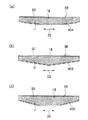
また、第1の実施形態では、下板16を平板とした例を示したが、図8(a)〜(c)の側面図に示す床版38のように、下板を下方に凸の形状となる下板40A〜40Cとしてもよい。図8(a)には、下方に湾曲した下板40Aが示され、図8(b)には、下方に尖った山形の下板40Bが示され、図8(c)には、下方に凸となる台形の下板40Cが示されている。
Further, in the first embodiment, an example in which the
図9(a)に示すように、床版42の下板44が下方に凸の形状となっている(下方に湾曲している)モデルにおいて、床版42の上面全体に鉛直荷重が作用して(鉛直方向の等分布荷重ω0が掛かって)床版42に曲げ荷重が作用した場合、図9(b)に示すように、下方に凸の形状となる下板44には下板44の両端を斜め上方へ引き上げる引張力Tが発生する。
As shown in FIG. 9A, in a model in which the
そして、下板44に発生する引張力Tによって床版42全体を上方向に押し上げる効果が生じ(押し上げ力ω1)、図9(c)の曲げモーメント図に示すように、床版42に生じた曲げモーメントが軽減される。図9(c)の横軸には、床版42の左端部からの距離が示され、図9(c)の縦軸には、床版42に等分布荷重ω0が掛かったときに床版42に生じる曲げモーメントが示されている。点線部分が、軽減された曲げモーメントとなっている。
また、下方に凸の形状となる下板44の引張剛性が床版42の面外剛性に大きく寄与するので、面外剛性を効果的に向上させることができる。
And the effect which pushes up the
Moreover, since the tensile rigidity of the
このような原理で床版38(図8(a)〜(c)を参照のこと)に生じた曲げモーメントが軽減されることにより、床版38内部に発生する応力が小さくなり、床版38の撓み量を小さくすることができる。また、コア部18に必要とされるせん断強度や、上板20に必要とされる座屈強度を小さくすることができる。例えば、コア部18を形成する材料にせん断強度の小さな材料を用いることが可能となる。
By reducing the bending moment generated in the floor slab 38 (see FIGS. 8A to 8C) based on such a principle, the stress generated in the
また、第1の実施形態では、下板及び上板の厚さを全長に渡って一様とした例を示したが、下板及び上板の全長に対して厚さを変化させてもよい。例えば、図10(a)、(b)の側面図に示すように、曲げモーメントが大きくなる、床版10の支持スパン方向22中央部付近の下板46、50、及び上板48、52の厚さを他の部分よりも大きくしてもよい。
In the first embodiment, the thickness of the lower plate and the upper plate is uniform over the entire length. However, the thickness may be changed with respect to the total length of the lower plate and the upper plate. . For example, as shown in the side views of FIGS. 10A and 10B, the
また、第1の実施形態で示した上板20の下面に、この上板20の座屈を防ぐ座屈防止手段として、薄い鋼板によって形成されたリブ54、56を設けてもよい。図11(a)の側面図に示すように、リブ54、56は、床版10の支持スパン方向22に等間隔に配置されている。また、リブ54、56は、上板20の下面に対して略直交するように設けられ、上端部が溶接等によって上板20に接合されている。
Moreover, you may provide the
図11(b)の平面図には、床版10の幅方向24全長に渡ってリブ54が設けられている例が示され、図11(c)の平面図には、上板20の真下にのみリブ56が設けられている例が示されている。
11 (b) shows an example in which
このようにすれば、上板20及びコア部18を有する床版10の上部に圧縮力が発生したときに、上板20が圧縮座屈するのを防ぐことができる。よって、板厚の薄い上板20でも圧縮力を負担することができる。
If it does in this way, when compressive force generate | occur | produces in the upper part of the
なお、座屈防止手段は、床版上部の座屈を防止することができる方法であればよく、コア部18の上面と上板20との一体化を高める方法を用いてもよい。例えば、座屈防止手段を、上板20の下面に設けてこの上板20の下面とコア部18の上面との一体化を高める突起部材(スタッド、エンボス加工等)としてもよいし、接着剤でコア部18と上板20との一体化を高めるようにしてもよい。接着剤には、エポキシ樹脂系、シリコーン樹脂系、ポリアミド系の接着剤等を用いることができる。
The buckling prevention means may be any method that can prevent buckling of the upper portion of the floor slab, and a method that enhances the integration of the upper surface of the
次に、本発明の第2の実施形態とその作用及び効果について説明する。 Next, a second embodiment of the present invention and its operation and effect will be described.
第2の実施形態の説明において、第1の実施形態と同じ構成のものは、同符号を付すると共に、適宜省略して説明する。
図12(a)、(b)の正面図には、床版58の接合方法が示されている。図12(a)には、床版58が接合される前の状態が示され、図12(b)には、床版58が接合された状態が示されている。
In the description of the second embodiment, the same components as those in the first embodiment are denoted by the same reference numerals and are appropriately omitted.
The front view of FIGS. 12A and 12B shows a method for joining the
床版58は、図2(c)で示した床版10において、コア部18の幅方向24端部に、切り欠60を形成したものである。図12(a)において、左側に配置されたコア部18の右端部には上面に切り欠60が形成され、右側に配置されたコア部18の左端部には下面に切り欠60が形成されている。これにより、コア部18の幅方向24端部において切り欠かれていない突起部62が切り欠60に挿入される。
In the
左側に配置されたコア部18の突起部62は、この突起部62の下面に設けられた下板16を有し、右側に配置されたコア部18の突起部62は、この突起部62の上面に設けられた上板20を有している。また、突起部62には鉛直方向に貫通する貫通孔64が形成されており、図12(b)に示すように、貫通孔64に貫通させたボルト66により上下に配置された突起部62同士をボルト接合する。これによって、左右に配置されたコア部18同士が接合される。
このような、切り欠60に突起部62を挿入する接合方法を用いれば、コア部18同士の接合部に生じる目違いを防止することができ、遮音性を向上させることができる。
The projecting
By using such a joining method in which the
コア部18の幅方向24端部に形成する切り欠は、図13(a)、(b)の正面図に示すような溝形状にしてもよい。図13(a)、(b)には、床版68の接合方法が示されている。図13(a)には、床版68が接合される前の状態が示され、図13(b)には、床版68が接合された状態が示されている。
The notch formed at the end in the
床版68は、図2(c)で示した床版10において、コア部18の幅方向24端部の一方に溝部70を形成し、コア部18の幅方向24端部の他方に、溝部70に挿入される凸部72を形成したものである。
In the
そして、図13(a)、(b)に示すように、左右に配置された床版68同士の接合面に接着剤(不図示)を塗布した後に、溝部70に凸部72を挿入することによって、左右に配置された床版68同士が接合される。
And as shown to Fig.13 (a), (b), after apply | coating an adhesive agent (not shown) to the joint surface of the
以上、本発明の第2の実施形態について説明した。 The second embodiment of the present invention has been described above.
なお、第2の実施形態では、図12(a)、(b)において、ボルト66により床版58同士を接合する例を示し、図13(a)、(b)において、接着剤により床版68同士を接合する例を示したが、床版58同士を接着剤によって接合してもよいし、床版68同士をボルトによって接合してもよい。
In addition, in 2nd Embodiment, the example which joins the
次に、本発明の第3の実施形態とその作用及び効果について説明する。 Next, a third embodiment of the present invention and its operation and effect will be described.
第3の実施形態の説明において、第1の実施形態と同じ構成のものは、同符号を付すると共に、適宜省略して説明する。
図14(a)〜(c)の正面図には、図7(a)、(b)で説明した方法と同様に、硬化したコア部18に下板16及び上板20を固定して製造される床版10の接合方法が示されている。図14(a)、(b)には、床版10が接合される前の状態が示され、図14(c)には、床版10が接合された状態が示されている。図14(a)〜(c)のコア部18上下面の幅方向24端部には、下板16又は上板20が配置される凹部74、76が形成されている。
In the description of the third embodiment, components having the same configurations as those of the first embodiment are denoted by the same reference numerals, and are appropriately omitted.
14A to 14C are manufactured by fixing the
床版10の接合方法は、まず、図14(a)に示すように、コア部18同士を隣り合わせて配置する(コア部配置工程)。
次に、隣り合うコア部18の一方から他方に渡って下板16及び上板20を配置し、接着剤(不図示)によってコア部18に下板16及び上板20を固定する(コア部連結工程)。これによって、左右に配置された床版10同士が接合される。なお、隣り合うコア部18の接合面(コア部18の端面)に接着剤を塗布しておいてもよい。また、下板16及び上板20の一方のみを隣り合うコア部18の一方から他方に渡って配置するようにしてもよい。
As a method for joining the
Next, the
このような接合方法を用いれば、コア部18の連結作業と同時に、下板16及び上板20をコア部18に固定することができるので、床版10の製造から設置までの間に要するトータルとしての作業手間を減らすことができる。
If such a joining method is used, since the
以上、本発明の第3の実施形態について説明した。 Heretofore, the third embodiment of the present invention has been described.
なお、第3の実施形態を応用し、図15(a)、(b)や、図16(a)〜(c)に示す方法によって床版同士を接合してもよい。 Note that the floor slabs may be joined to each other by the method shown in FIGS. 15A and 15B and FIGS. 16A to 16C by applying the third embodiment.
図15(a)には、床版10が接合される前の状態が示され、図15(b)には、床版10が接合された状態が示されている。この接合方法では、隣り合って配置されるコア部18の一方に、下板16又は上板20が予め固定されている。
FIG. 15A shows a state before the
図16(a)、(b)には、床版80が接合される前の状態が示され、図16(c)には床版80が接合された状態が示されている。この方法では、隣り合って配置されるコア部18同士の間に硬化材としてのモルタルVを充填することによって接合している。図16(a)において、下板16は接着剤(不図示)によってコア部18に固定される。
16A and 16B show a state before the
この接合方法では、図16(b)に示すように、下板16をモルタルVの打設時の底型枠として利用することができる。なお、図16(a)に示すように、コア部18同士の接合面(端面)には、コッター溝78を形成するのが好ましい。また、図16(c)に示すように、隣り合って配置されるコア部18同士が接合された状態において、下板16と上板20とは、幅方向24に対して互い違いに配置されている。
In this joining method, as shown in FIG. 16B, the
以上、本発明の第1〜第3の実施形態について説明した。 The first to third embodiments of the present invention have been described above.
なお、第1〜第3の実施形態では、下板16及び上板20を、支持スパン方向22のコア部18全長に渡って配置した例を示したが、下板16及び上板20は、支持スパン方向22のコア部18全長の一部に配置してもよい。例えば、図17(a)、(b)に示す床版82のように、下板16及び上板20を配置してもよい。
In the first to third embodiments, the example in which the
図17(a)は、床版82の上方から床版82の上面を見た平面図である。コア部18の支持スパン方向22両端に上板20が配置されており、床版82に作用する圧縮力はコア部18の上部が負担する。
FIG. 17A is a plan view of the top surface of the
図17(b)は、床版82の下方から床版82の下面を見た平面図である。コア部18の支持スパン方向22中央に下板16が配置されており、理論的に曲げモーメントが0となるコア部18の支持スパン方向22両端には下板16が配置されていない。
図17(a)、(b)のようにすれば、コア部18に設ける下板16及び上板20を減らすことができ、床版82の軽量化を図ることができる。
FIG. 17B is a plan view of the bottom surface of the
17A and 17B, the
また、第1〜第3の実施形態では、床版10、38、58、68、80を建築物の床構造を構成する一方向スラブとして使用する例を示したが、建築物の床構造を構成する二方向スラブに床版10、38、58、68、80を応用することができる。例えば、図18(a)、(b)、図19(a)〜(c)、及び図20(a)〜(c)に示す床版84、90、92としてもよい。図18(a)、(b)、図19(a)〜(c)、及び図20(a)〜(c)において、矢印86は、支持スパンX方向(以下、「支持スパンX方向86」とする)を意味し、矢印88は、支持スパンX方向86に直交する支持スパンY方向(以下、「支持スパンY方向88」とする)を意味する。
Moreover, in the 1st-3rd embodiment, although the example which uses the
図18(a)は、床版84の上方から床版84の上面を見た平面図である。コア部18の周縁部(コア部18の支持スパンX方向86及び支持スパンY方向88の両端部)に上板20が配置されており、床版84に作用する圧縮力はコア部18の中央上部が負担する。
FIG. 18A is a plan view of the top surface of the
図18(b)は、床版84の下方から床版84の下面を見た平面図である。コア部18の中央部(コア部18の支持スパンX方向86及び支持スパンY方向88の中央部)に下板16が配置されており、理論的に曲げモーメントが0となるコア部18の周縁部には下板16が配置されていない。
FIG. 18B is a plan view of the bottom surface of the
床版90の上方から床版90の上面を見た図19(a)の平面図、図19(a)のC−C矢視図である図19(b)、及び図19(a)のD−D矢視図である図19(c)に示すように、床版90では、格子状に形成された上板20及び下板16が、コア部18の上下面に設けられている。図19(b)、(c)に示すように、上板20及び下板16はコア部18に埋設されており、これによって床版90の上下面の平面性が確保されている。
FIG. 19A is a plan view of the top surface of the
床版92の上方から床版92の上面を見た図20(a)の平面図、図20(a)のE−E矢視図である図20(b)、及び図20(a)のF−F矢視図である図20(c)に示すように、床版92では、帯状に形成された上板20及び下板16が、コア部18の上下面に格子状に配置されている。床版92では、上板20及び下板16の配置ピッチの設定によって、床版92に与える面外剛性を調整することができる。
FIG. 20A is a plan view of the top surface of the
また、第1〜第3の実施形態では、床版10、38、58、68、80の端部に周辺フレームを設けていない例を示したが、床版10、38、58、68、80の端部に型鋼等の周辺フレームを設けてもよい。例えば、図21の斜視図に示すように、床版10の支持スパン方向22両端にC型鋼材94を設けるようにしてもよい。
In the first to third embodiments, an example in which the peripheral frame is not provided at the end of the
また、第1の実施形態では、図3(a)〜(c)に示す床版の製造方法によって1つの床版10を製造する一例を示したが、一度に複数の床版10を製造してもよい。
例えば、図22の斜視図に示す床版製造器96によって一度に複数の床版10を製造することができる。床版製造器96は、軽量気泡コンクリートUが流し込まれる型枠98と、この型枠98に着脱可能に配置される移動仕切板100(図24を参照のこと)とを備えている。
In the first embodiment, an example in which one
For example, a plurality of
型枠98は鋼製の箱型に形成され、対向して立設される側板102A、102Bと、この側板102A、102Bと直交して立設される側板104A、104Bと、底板106とから構成されている。
The
側板102A、102B、104A、104B、及び底板106は、ボルト(不図示)等によって相互に接合され、型枠98内に軽量気泡コンクリートUを流し込んだときにこの軽量気泡コンクリートUが接合部から漏れないように、接合部にはシール処理が施されている。
The
側板104A、104Bには、側板104A、104Bの内面と板面118A、118Bが略直交するように固定仕切板108A、108Bが固定されている。固定仕切板108A、108Bは、側板104A、104Bの短手方向114に対して等間隔に複数配置されており、この間隔が床版10の上下方向の厚みとなる。
Fixed
型枠98の内側へ向かう固定仕切板108A、108Bの先端面には、移動仕切板100の側端部に形成された突出部110が挿入される溝112が形成されている。
また、側板104A、104Bにおいて固定仕切板108A、108Bが固定されていない部分には、貫通孔116が複数形成されている。
Further, a plurality of through
床版製造器96により複数の床版10を製造する方法は、先ず、図23の斜視図に示すように、固定仕切板108A、108Bの板面118A、及び側板102Aの内面に、上板20を粘着力の弱い両面テープ等で貼り付け、固定仕切板108A、108Bの板面118B、及び側板102Bの内面に、下板16を粘着力の弱い両面テープ等で貼り付ける。
As shown in the perspective view of FIG. 23, the method of manufacturing a plurality of
また、型枠98内に軽量気泡コンクリートUを流し込んだときにこの軽量気泡コンクリートUが貫通孔116から漏れないように、全ての貫通孔116を栓120によって塞ぐ(図26(a)の平面図を参照のこと)。
Further, all the through
次に、図24の斜視図に示すように、型枠98内に軽量気泡コンクリートUを流し込んだ後に、移動仕切板100の突出部110を固定仕切板108A、108Bの溝112に挿入するようにして、固定仕切板108Aと固定仕切板108Bとの間に移動仕切板100を挿入し、型枠98内に移動仕切板100を配置する(図26(b)の平面図を参照のこと)。なお、型枠98内への移動仕切板100の配置は、型枠98内に軽量気泡コンクリートUを流し込む前に行ってもよい。
Next, as shown in the perspective view of FIG. 24, after the lightweight cellular concrete U is poured into the
次に、軽量気泡コンクリートUが半硬化状態のコア部18となった後に、移動仕切板100を引き抜き、側板102A、102Bを脱型する。なお、半硬化状態とは、移動仕切板100を引き抜き、側板102A、102Bを脱型した状態において、コア部18の形状が維持される程度に軽量気泡コンクリートUが硬化した状態を意味する。
Next, after the lightweight cellular concrete U becomes the
次に、図25の斜視図に示すように、全ての栓120を外した後にコア部18をオートクレーブ養生し、コア部18を完全に硬化させることによって複数の床版10が完成する(図26(c)の平面図を参照のこと)。
次に、側板104A、104B、及び底板106を脱型し、複数の床版10を取り出す。
Next, as shown in the perspective view of FIG. 25, after removing all the
Next, the
このように、複数の床版10を一度に製造する場合においても、半硬化状態のコア部18を完全に硬化させるためのオートクレーブ養生時において、下板16や上板20が設けられていない部分を介してコア部18内に高温蒸気(矢印122)を流通させることができる。すなわち、下板16及び上板20がコア部18に設けられている状態で、オートクレーブ養生を効果的に行うことができる。
In this way, even when a plurality of
また、第1〜第3の実施形態で示した床版10、38、58、68、80に、面外剛性を向上させるための工夫を施してもよい。例えば、支持スパン方向22に渡って、下方に凸の形状となるように鉄筋を床版内部に配置してもよいし、この鉄筋に下端部が接触するように図11(a)〜(c)で示したリブ54、56を設けてもよい。また、例えば、床版10、38、58、68、80の上板20、48、52下面に平面視にてX形状の補強板を設けてもよい。
また、第1〜第3の実施形態で示した床版10、38、58、68、80の内部に、中空部を形成して床版の更なる軽量化を図ってもよい。
Moreover, you may give the device for improving out-of-plane rigidity to the
Further, the floor slab may be further reduced in weight by forming a hollow portion inside the
以上、本発明の第1〜第3の実施形態について説明したが、本発明はこうした実施形態に何等限定されるものでなく、第1〜第3の実施形態を組み合わせて用いてもよいし、本発明の要旨を逸脱しない範囲において、種々なる態様で実施し得ることは勿論である。 The first to third embodiments of the present invention have been described above, but the present invention is not limited to such embodiments, and the first to third embodiments may be used in combination. Needless to say, the present invention can be implemented in various modes without departing from the gist of the present invention.
(実施例) (Example)
本実施例では、本発明の第1の実施形態で示した床版10に対して実施した実験結果について示す。
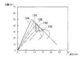
図27は、図2(a)〜(c)、及び図5(a)で示した床版10に対して実施した実験結果のグラフである。横軸には、床版10の支持スパン方向22中央の変位が示され、縦軸には、床版10に加えた荷重Pの値が示されている。
In this example, experimental results performed on the
FIG. 27 is a graph of the results of experiments performed on the
図27の値124、126、128、130、132は、支持スパン方向22の全長が3,000mmの床版10に対して行った4点曲げ試験の計測値である。図28に示す寸法位置にP/2の荷重が作用するように床版10に荷重Pを加えた。
値124は、図5(a)において、幅方向24の床版10の長さL1を600mm、幅方向24の下板16の長さL2を300mm、幅方向24の上板20の長さL3を300mm、上板20及び下板16の厚さを2.3mmとしたときの値である。最大荷重は49.8kNとなった。
The
値126は、図5(a)において、幅方向24の床版10の長さL1を600mm、幅方向24の下板16の長さL2を400mm、幅方向24の上板20の長さL3を400mm、上板20及び下板16の厚さを1.2mmとしたときの値である。最大荷重は48.3kNとなった。
The
値128は、図5(a)において、幅方向24の床版10の長さL1を600mm、幅方向24の下板16の長さL2を300mm、幅方向24の上板20の長さL3を300mm、上板20及び下板16の厚さを1.2mmとしたときの値である。最大荷重は40.0kNとなった。
The
値130は、図2(a)、(b)において、幅方向24の床版10の長さL1を600mm、幅方向24の下板16の長さL2を150mm、幅方向24の上板20の長さL3を150mm、上板20及び下板16の厚さを1.2mmとしたときの値である。最大荷重は42.6kNとなった。
2A and 2B, the
値132は、図5(a)において、幅方向24の床版10の長さL1を600mm、幅方向24の下板16の長さL2を200mm、幅方向24の上板20の長さL3を200mm、上板20及び下板16の厚さを1.2mmとしたときの値である。最大荷重は34.5kNとなった。
The
なお、値124、126、128、130、132において、下板16及び上板20は同じ金属材料によって形成され、コア部18は同じ配合の軽量気泡コンクリートUによって形成されている。
In the
図27の値124、126、128、130、132により、下板16及び上板20の総体積が大きい(値124、126、128、130、132の傾きが大きい)ほど、床版10の面外剛性が大きくなることがわかる。
According to the
図27の値128と値130とは、下板16及び上板20の総体積が等しいので、床版10の面外剛性(値128と値130との傾き)は、ほぼ等しくなっている。
よって、床版10に設けられる下板16及び上板20の大きさ(平面積)及び厚さによって面外剛性を制御することができる。
Since the total volume of the
Therefore, the out-of-plane rigidity can be controlled by the size (planar area) and thickness of the
10、38、58、68、80、82、84、90、92 床版
16、40A〜40C、46、50 下板
18 コア部
20、48、52 上板
54、56 リブ(座屈防止手段)
U 軽量気泡コンクリート
10, 38, 58, 68, 80, 82, 84, 90, 92
U Lightweight cellular concrete
Claims (6)
前記下板の上方に配置された金属製の上板と、
前記下板と前記上板との間に形成され前記下板及び前記上板と一体となるコア部と、
を有し、
前記下板及び前記上板は、前記コア部の支持スパン方向全長に渡って配置され、
前記下板は、前記コア部に対向する面積が前記コア部の下面の面積よりも小さく、前記上板は、前記コア部に対向する面積が前記コア部の上面の面積よりも小さい、
又は、前記下板は、前記コア部に対向する面積が前記コア部の下面の面積よりも小さく、前記上板は、前記コア部に対向する面積が前記コア部の上面の面積と等しい床版。 A metal base plate,
A metal upper plate disposed above the lower plate;
A core portion formed between the lower plate and the upper plate and integrated with the lower plate and the upper plate;
Have
The lower plate and the upper plate are arranged over the entire length in the support span direction of the core portion,
The lower plate has an area facing the core portion smaller than an area of the lower surface of the core portion, and the upper plate has an area facing the core portion smaller than an area of the upper surface of the core portion.
Alternatively, the lower plate has an area facing the core portion smaller than the area of the lower surface of the core portion, and the upper plate has a floor slab whose area facing the core portion is equal to the area of the upper surface of the core portion. .
前記下板の上方に配置された金属製の上板と、A metal upper plate disposed above the lower plate;
前記下板と前記上板との間に形成され前記下板及び前記上板と一体となるコア部と、A core portion formed between the lower plate and the upper plate and integrated with the lower plate and the upper plate;
を有し、Have
前記下板は、前記コア部に対向する面積が前記コア部の下面の面積と等しく、前記上板は、前記コア部に対向する面積が前記コア部の上面の面積よりも小さい床版。The lower plate is a floor slab whose area facing the core portion is equal to the area of the lower surface of the core portion, and the upper plate is smaller in area facing the core portion than the area of the upper surface of the core portion.
Priority Applications (1)
| Application Number | Priority Date | Filing Date | Title |
|---|---|---|---|
| JP2009118841A JP5275896B2 (en) | 2009-05-15 | 2009-05-15 | Floor slabs and buildings |
Applications Claiming Priority (1)
| Application Number | Priority Date | Filing Date | Title |
|---|---|---|---|
| JP2009118841A JP5275896B2 (en) | 2009-05-15 | 2009-05-15 | Floor slabs and buildings |
Publications (2)
| Publication Number | Publication Date |
|---|---|
| JP2010265691A JP2010265691A (en) | 2010-11-25 |
| JP5275896B2 true JP5275896B2 (en) | 2013-08-28 |
Family
ID=43362885
Family Applications (1)
| Application Number | Title | Priority Date | Filing Date |
|---|---|---|---|
| JP2009118841A Expired - Fee Related JP5275896B2 (en) | 2009-05-15 | 2009-05-15 | Floor slabs and buildings |
Country Status (1)
| Country | Link |
|---|---|
| JP (1) | JP5275896B2 (en) |
Families Citing this family (3)
| Publication number | Priority date | Publication date | Assignee | Title |
|---|---|---|---|---|
| KR101540849B1 (en) * | 2013-07-10 | 2015-07-30 | 현대중공업 주식회사 | Aboveground type liquid storage tank |
| KR101540848B1 (en) * | 2013-07-10 | 2015-08-06 | 현대중공업 주식회사 | Aboveground type liquid storage tank |
| KR101540850B1 (en) * | 2013-07-10 | 2015-07-30 | 현대중공업 주식회사 | Aboveground type liquid storage tank |
Family Cites Families (4)
| Publication number | Priority date | Publication date | Assignee | Title |
|---|---|---|---|---|
| JPH02111710U (en) * | 1989-02-23 | 1990-09-06 | ||
| JPH0849395A (en) * | 1994-08-09 | 1996-02-20 | Sumitomo Rubber Ind Ltd | Double floor concrete panel |
| JPH11324170A (en) * | 1998-05-08 | 1999-11-26 | Asahi Chem Ind Co Ltd | Bearing panel and joint structure of bearing panel |
| JP2004353289A (en) * | 2003-05-29 | 2004-12-16 | Sekisui House Ltd | How to fix metal skin panels to beams |
-
2009
- 2009-05-15 JP JP2009118841A patent/JP5275896B2/en not_active Expired - Fee Related
Also Published As
| Publication number | Publication date |
|---|---|
| JP2010265691A (en) | 2010-11-25 |
Similar Documents
| Publication | Publication Date | Title |
|---|---|---|
| US6230465B1 (en) | Precast concrete structural modules | |
| EP2447025B1 (en) | Method for producing concrete trestle, concrete trestle, and connecting member | |
| US20200240144A1 (en) | Thermal-insulated exterior wall boards, dedicated molds and making methods thereof | |
| CN104727441B (en) | Prestress assembled concrete beam column joint structure and construction method thereof | |
| US10227777B2 (en) | Method for producing a concrete component, prefabricated structural element of a concrete component, and concrete component | |
| JP5275896B2 (en) | Floor slabs and buildings | |
| KR20120087640A (en) | Remodelling Construction Method by Inserting External Precast Concrete Wall Panel into the Internal Area of Beam-column Frame of Building and that Precast Concrete Panel | |
| JP2012007348A (en) | Floor slab | |
| JP2009084908A (en) | Floor plate unit with void forms, and composite hollow floor plate | |
| KR101250864B1 (en) | Wall and building using the same | |
| CN116502316B (en) | Node bearing capacity regulating and controlling method of modularized hybrid structure | |
| JP4834890B2 (en) | Prestressing method for filling part between precast concrete members | |
| KR101233120B1 (en) | Foundation structure and construction method thereof | |
| JP5203849B2 (en) | Floor slab, method for manufacturing floor slab and building | |
| CN102356203A (en) | Wall element and method of manufacturing same | |
| KR101233119B1 (en) | Pannel and construction method for building using the same | |
| JP6838984B2 (en) | Temporary receiving structure of existing column axial force and seismic isolation construction method | |
| JPH1018491A (en) | Composite lightweight floor slab, its manufacturing method and construction method | |
| JP4476091B2 (en) | Precast concrete floor board and manufacturing method thereof | |
| JP4155880B2 (en) | Buried formwork | |
| JP2025082022A (en) | Wall junction structure for building | |
| JP2023112579A (en) | Column reinforcement structure and column reinforcement method | |
| AU730218B2 (en) | Pre-cast concrete walling system | |
| KR20180070097A (en) | Prestressed Hybrid Wide Flange Girder System Suitable For Resisting Negative Moments At Construction Stage | |
| KR20160073399A (en) | Machine table foundation |
Legal Events
| Date | Code | Title | Description |
|---|---|---|---|
| A621 | Written request for application examination |
Free format text: JAPANESE INTERMEDIATE CODE: A621 Effective date: 20120327 |
|
| A131 | Notification of reasons for refusal |
Free format text: JAPANESE INTERMEDIATE CODE: A131 Effective date: 20130305 |
|
| A521 | Written amendment |
Free format text: JAPANESE INTERMEDIATE CODE: A523 Effective date: 20130416 |
|
| TRDD | Decision of grant or rejection written | ||
| A01 | Written decision to grant a patent or to grant a registration (utility model) |
Free format text: JAPANESE INTERMEDIATE CODE: A01 Effective date: 20130514 |
|
| A61 | First payment of annual fees (during grant procedure) |
Free format text: JAPANESE INTERMEDIATE CODE: A61 Effective date: 20130516 |
|
| R150 | Certificate of patent or registration of utility model |
Free format text: JAPANESE INTERMEDIATE CODE: R150 Ref document number: 5275896 Country of ref document: JP Free format text: JAPANESE INTERMEDIATE CODE: R150 |
|
| LAPS | Cancellation because of no payment of annual fees |