JP5239631B2 - Vehicle seat coupling device - Google Patents
Vehicle seat coupling device Download PDFInfo
- Publication number
- JP5239631B2 JP5239631B2 JP2008216515A JP2008216515A JP5239631B2 JP 5239631 B2 JP5239631 B2 JP 5239631B2 JP 2008216515 A JP2008216515 A JP 2008216515A JP 2008216515 A JP2008216515 A JP 2008216515A JP 5239631 B2 JP5239631 B2 JP 5239631B2
- Authority
- JP
- Japan
- Prior art keywords
- guide
- coupling device
- vehicle seat
- ratchet
- state
- Prior art date
- Legal status (The legal status is an assumption and is not a legal conclusion. Google has not performed a legal analysis and makes no representation as to the accuracy of the status listed.)
- Active
Links
Images




Classifications
-
- B—PERFORMING OPERATIONS; TRANSPORTING
- B60—VEHICLES IN GENERAL
- B60N—SEATS SPECIALLY ADAPTED FOR VEHICLES; VEHICLE PASSENGER ACCOMMODATION NOT OTHERWISE PROVIDED FOR
- B60N2/00—Seats specially adapted for vehicles; Arrangement or mounting of seats in vehicles
- B60N2/02—Seats specially adapted for vehicles; Arrangement or mounting of seats in vehicles the seat or part thereof being movable, e.g. adjustable
- B60N2/22—Seats specially adapted for vehicles; Arrangement or mounting of seats in vehicles the seat or part thereof being movable, e.g. adjustable the back-rest being adjustable
- B60N2/235—Seats specially adapted for vehicles; Arrangement or mounting of seats in vehicles the seat or part thereof being movable, e.g. adjustable the back-rest being adjustable by gear-pawl type mechanisms
- B60N2/2356—Seats specially adapted for vehicles; Arrangement or mounting of seats in vehicles the seat or part thereof being movable, e.g. adjustable the back-rest being adjustable by gear-pawl type mechanisms with internal pawls
- B60N2/236—Seats specially adapted for vehicles; Arrangement or mounting of seats in vehicles the seat or part thereof being movable, e.g. adjustable the back-rest being adjustable by gear-pawl type mechanisms with internal pawls linearly movable
-
- B—PERFORMING OPERATIONS; TRANSPORTING
- B60—VEHICLES IN GENERAL
- B60N—SEATS SPECIALLY ADAPTED FOR VEHICLES; VEHICLE PASSENGER ACCOMMODATION NOT OTHERWISE PROVIDED FOR
- B60N2/00—Seats specially adapted for vehicles; Arrangement or mounting of seats in vehicles
- B60N2/68—Seat frames
- B60N2/682—Joining means
Landscapes
- Engineering & Computer Science (AREA)
- Aviation & Aerospace Engineering (AREA)
- Transportation (AREA)
- Mechanical Engineering (AREA)
- Seats For Vehicles (AREA)
- Chairs For Special Purposes, Such As Reclining Chairs (AREA)
Description
本発明は、車両用シートの連結装置に関する。詳しくは、二つの対象部材を互いに相対回転可能に連結する車両用シートの連結装置に関する。 The present invention relates to a connecting device for a vehicle seat. Specifically, the present invention relates to a vehicle seat coupling device that couples two target members such that they can rotate relative to each other.
従来、車両用シートにおいて、シートバックがリクライニング装置を介してシートクッションと連結されており、その背凭れ角度の調整操作が行えるようになっているものが知られている。ここで、下記特許文献1には、上記したリクライニング装置の構成が開示されている。この開示では、リクライニング装置は、シートバックの骨格フレーム(バックフレーム)に一体的に連結される円盤形状のラチェットと、シートクッションの骨格フレーム(クッションフレーム)に一体的に連結される円盤形状のガイドとが、互いに相対回転可能となるように板厚方向に組み付けられて構成されている。
2. Description of the Related Art Conventionally, in a vehicle seat, a seat back is connected to a seat cushion via a reclining device, and an operation for adjusting a backrest angle is known. Here, the following
上記したリクライニング装置は、ラチェットとバックフレームとの連結が、ラチェットから板厚方向に円筒状に突出して形成された円筒部が、バックフレームに板厚方向に貫通形成された嵌合孔内に嵌め込まれて、これら嵌合部分が互いに溶接されて接合されることによって行われている。
しかし、上記開示の従来技術では、ラチェット及びガイドの双方がそれらの外周部に跨って嵌め込まれた円筒状の外周リングによって板厚方向に挟持されて外れ止めされており、ラチェットの最外周部分をバックフレームに嵌合させて連結強度を高めるようにする構成をとることができない構成となっている。 However, in the prior art disclosed above, both the ratchet and the guide are clamped in the plate thickness direction by the cylindrical outer ring fitted over the outer peripheral portion thereof to prevent the ratchet and guide from coming off. It is a structure which cannot take the structure which fits a back frame and raises connection strength.
本発明は、上記した問題を解決するものとして創案されたものであって、本発明が解決しようとする課題は、車両用シートの連結装置を、連結対象となる部材に対して最外周部分で接合させられるようにして、連結強度を高めることにある。 The present invention has been devised as a solution to the above-described problems, and the problem to be solved by the present invention is to provide a vehicle seat connecting device at the outermost peripheral portion with respect to a member to be connected. The purpose of this is to increase the connection strength.
上記課題を解決するために、本発明の車両用シートの連結装置は次の手段をとる。
先ず、第1の発明は、連結対象となる二つの対象部材を互いに相対回転可能に連結する車両用シートの連結装置であって、二枚の連結部材と保持部材とを有する。二枚の連結部材は、二つの対象部材の一方側或いは他方側にそれぞれ一体的に連結されて、互いに相対回転可能に板合わせ方向に組み付けられる。保持部材は、二枚の連結部材の外周部に跨って組み付けられて、これら連結部材を板合わせ方向に組み付けた状態に保持する。保持部材の外周部には、回転半径方向に開口した開口部が形成されている。二枚の連結部材のうち少なくとも一方は、保持部材の開口部から突出する突出部を有し、突出部とその連結対象となる側の対象部材とが一体的に連結されている。
In order to solve the above-mentioned problems, the vehicle seat coupling device of the present invention takes the following means.
First, the first invention is a vehicle seat coupling device that couples two target members to be coupled to each other so as to be relatively rotatable, and includes two coupling members and a holding member. The two connecting members are integrally connected to one side or the other side of the two target members, respectively, and are assembled to each other so as to be rotatable relative to each other. The holding member is assembled across the outer peripheral portions of the two connecting members, and holds the connecting members in a state of being assembled in the plate alignment direction. An opening that opens in the rotational radius direction is formed on the outer periphery of the holding member. At least one of the two connecting members has a protruding portion that protrudes from the opening of the holding member, and the protruding portion and the target member on the side to be connected are integrally connected.
この第1の発明によれば、二枚の連結部材のうち少なくとも一方は、保持部材の開口部から回転半径方向に突出した突出部がその連結対象となる対象部材に当てられて一体的に連結される。したがって、同連結部材は、その最外周部分が対象部材と一体的に連結されることとなるため、かかる連結強度を高めることができる。 According to the first aspect of the invention, at least one of the two connecting members is integrally connected with the projecting portion protruding in the rotational radius direction from the opening of the holding member being applied to the target member to be connected. Is done. Therefore, since the outermost peripheral portion of the connecting member is integrally connected to the target member, the connection strength can be increased.
次に、第2の発明は、上述した第1の発明において、突出部は、その連結対象となる側の対象部材に対して、回転半径方向に突き当てられて溶接により接合されている。 Next, according to a second aspect, in the first aspect described above, the protrusion is abutted in the rotational radial direction and joined to the target member on the side to be connected by welding.
この第2の発明によれば、突出部と対象部材とを回転半径方向に突き当てて溶接するようにしたことにより、これらを板厚方向に突き当てて連結する構成と比べると、板厚方向の設置スペースを狭くすることができる。 According to the second aspect of the present invention, the projection and the target member are abutted and welded in the rotational radius direction, so that compared with the configuration in which these are abutted and coupled in the thickness direction, the thickness direction The installation space can be reduced.
次に、第3の発明は、上述した第2の発明において、突出部とその連結対象となる側の対象部材との溶接は、同接合部への板厚方向のレーザー溶接によって行われており、このレーザー溶接によって接合部の板厚方向の端面に形成される裏波が外部に対して露呈する。 Next, according to a third invention, in the second invention described above, the welding of the projecting portion and the target member to be connected to the projecting portion is performed by laser welding in the plate thickness direction to the joint portion. The back wave formed on the end face in the plate thickness direction of the joint is exposed to the outside by this laser welding.
この第3の発明によれば、突出部と対象部材との接合を板厚方向へのレーザー溶接によって行うようにしたことにより、アーク溶接やボルト締結等の接合物の重量が添加されてしまう構成と比べると、構成全体の重量を軽くすることができる。また、レーザー溶接の裏波(溶接痕)が接合部の板厚方向の端面に外部に露呈して形成されるようにしたことで、レーザー溶接が適正に行われたかどうかの確認を、外部から裏波を視認することによって容易に行うことができる。 According to the third aspect of the invention, the joining of the projecting portion and the target member is performed by laser welding in the plate thickness direction, so that the weight of the joined object such as arc welding or bolt fastening is added. As compared with the above, the weight of the entire configuration can be reduced. In addition, by confirming whether laser welding has been performed properly by externally exposing the back surface of the laser welding (welding marks) to the outside in the plate thickness direction end surface of the joint, This can be done easily by visually recognizing the back wave.
次に、第4の発明は、上述した第1から第3のいずれかの発明において、突出部及びその連結対象となる側の対象部材は、それらの互いに接合される接合面に形成された各噛合歯が互いに噛合した状態で接合されている。 Next, according to a fourth invention, in any one of the first to third inventions described above, the projecting portion and the target member on the side to be connected to each other are formed on their joint surfaces. The meshing teeth are joined in a state of meshing with each other.
この第4の発明によれば、突出部と対象部材との接合が互いの接合面に形成された噛合歯の噛合を伴って行われていることにより、両者の連結強度を更に高めることができる。 According to this 4th invention, joining of a protrusion part and an object member is performed with the meshing | engagement of the meshing teeth formed in the mutual joining surface, and can further raise both connection strength. .
次に、第5の発明は、上述した第4の発明において、突出部とその連結対象となる側の対象部材との接合は、それらの接合面に形成された各噛合歯が噛合した部位が溶接されて行われており、この溶接のビード幅は、各噛合歯同士が噛合する歯底間の寸法よりも広くなっている。 Next, a fifth aspect of the present invention is the above-described fourth aspect of the present invention, in which the projecting portion and the target member on the side to be connected are joined by the portions where the respective meshing teeth formed on the joint surfaces mesh with each other. The welding bead width is wider than the dimension between the roots where the meshing teeth mesh with each other.
この第5の発明によれば、溶接のビード幅が各噛合歯が噛合する歯底間の寸法よりも広くなっていることにより、噛合歯同士が噛合した部位の他、噛合歯同士が噛合していない部位にも溶接による接合強度をもたせることができるため、接合強度を一層高めることができる。 According to the fifth aspect of the invention, since the weld bead width is wider than the dimension between the roots where the meshing teeth mesh, the meshing teeth mesh with each other in addition to the portion where the meshing teeth mesh with each other. Since the joining strength by welding can be given also to the site | part which is not, joining strength can be raised further.
以下に、本発明を実施するための最良の形態の実施例について図面を用いて説明する。 Embodiments of the best mode for carrying out the present invention will be described below with reference to the drawings.
始めに、実施例1の車両用シートの連結装置の構成について、図1〜図7を用いて説明する。ここで、図2には、本実施例の車両用シート1の概略構成が示されている。この車両用シート1は、背凭れとなるシートバック2が、その左右両サイドの下部位置に配設された左右一対のリクライニング装置4,4によって、着座部となるシートクッション3と連結されている。ここで、リクライニング装置4,4が本発明の車両用シートの連結装置に相当する。
First, the configuration of the vehicle seat coupling device according to the first embodiment will be described with reference to FIGS. Here, FIG. 2 shows a schematic configuration of the
これらリクライニング装置4,4は、互いのロック解除の切換え操作を行う操作軸4c,4cが、連結ロッド4rによって互いに一体的に連結されて構成されている。これにより、各リクライニング装置4,4は、シートバック2の背凭れ角度を固定したロック状態と、この固定状態を解除してシートバック2の背凭れ角度調整を行える状態にする解除状態とに、互いの作動状態が同期して切換えられるようになっている。ここで、各リクライニング装置4,4は、常時は附勢によってロックした作動状態に保持されている。
The reclining
そして、各リクライニング装置4,4は、シートクッション3の側部位置に設けられた操作レバー5の引き上げ操作を行うことにより、それらのロック状態が一斉に解除操作される。これにより、シートバック2の背凭れ角度の固定状態が解かれるため、その背凭れ角度の調整操作が行える状態となる。そして、シートバック2の背凭れ角度を調整し、操作レバー5の解除操作をやめることにより、各リクライニング装置4,4が再び附勢によってロック状態に戻されるため、シートバック2がその調整された背凭れ角度位置に固定される。
Each reclining
ここで、シートバック2は、シートクッション3との間に掛着された図示しない附勢ばねの附勢力によって、常時は前倒しの回動方向に附勢されている。したがって、車両用シート1が着座使用されていない状態で、上述した各リクライニング装置4,4のロック状態を解除することにより、シートバック2は附勢によって前倒しされて、シートクッション3の上面部に畳み込まれることとなる。
Here, the
このとき、各リクライニング装置4,4は、通常、シートバック2が背凭れとして使用される角度領域にある時には、操作レバー5の解除操作をやめることによって、附勢によってロック状態に戻される。しかし、各リクライニング装置4,4の回転角度領域には、上記した解除操作をやめた際に附勢によってロック状態に戻されるロックゾーンの角度領域と、解除操作をやめてもロック状態には戻されないフリーゾーンの角度領域とが設定されている。
At this time, the reclining
前者のロックゾーンは、通常、シートバック2が背凭れとして使用される角度領域、具体的にはシートバック2が直立姿勢となる角度位置から後方側に倒し込まれる角度領域に設定されている。そして、後者のフリーゾーンは、シートバック2が背凭れとして使用されることのない前倒れ姿勢の角度領域、具体的にはシートバック2が直立姿勢となる角度位置から前方側に倒し込まれる角度領域に設定されている。
The former lock zone is normally set to an angular region where the
したがって、シートバック2を前倒し操作するために、各リクライニング装置4,4のロック状態を解除して、シートバック2が直立姿勢から少しでも前に傾いたら、あとは解除操作をやめてしまっても、シートバック2はシートクッション3の上面部に畳み込まれる位置まで自然と倒し込まれていく。以下、リクライニング装置4,4の構成について詳しく説明をする。なお、各リクライニング装置4,4は、互いに左右対称の構成となっているが、実質的には同じ構成となっている。したがって、以下ではこれらを代表して、図2の紙面向かって右側に示されているリクライニング装置4の構成についてのみ説明をする。
Therefore, in order to operate the seat back 2 forward, the reclining
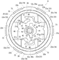
このリクライニング装置4は、図1に示されるように、略円板形状のラチェット10及びガイド20と、これらの円板面の間に挟まれて配置される上下一対のポール30,30及びスライドカム40と、このスライドカム40をスライド操作するためのヒンジカム50と、このヒンジカム50を回動附勢するための附勢ばね60と、ラチェット10及びガイド20を互いに板厚方向(軸方向)に挟み込んだ状態に保持するための保持部材70とが一つに組み付けられて構成されている。ここで、ガイド20が本発明の一方の連結部材に相当し、ラチェット10が本発明の他方の連結部材に相当する。
As shown in FIG. 1, the reclining
詳しくは、ラチェット10には、その円板部11の外周縁において、板厚方向に円筒状に突出する円筒部12が形成されている。この円筒部12は、円板部11の外周縁が板厚方向に半抜き加工されることによって押し出されて形成されている。そして、この円筒部12の内周面には、内歯の形成された内周歯面12aと、内歯のない平坦な湾曲面として形成された乗上げ面12b,12bとが円周方向に並んで形成されている。ここで、乗上げ面12b,12bは、円筒部12の軸対称となる二箇所の位置に配置されており、それぞれ、内周面が内周歯面12aよりも半径方向の内方側に突出した平坦な湾曲面とされて形成されている。
Specifically, the
上記した乗上げ面12b,12bは、図6に示されるように、いずれのポール30,30とも干渉しない円周方向の配置状態の時には、各ポール30,30がラチェット10の内周歯面12aと噛合する半径方向外方側への噛合移動を許容する。したがって、これら乗上げ面12b,12bと各ポール30,30との干渉が起こらない円周方向の回転角度領域が、各ポール30,30とラチェット10の内周歯面12aとの噛合が許容されるロックゾーンとして設定される。
As shown in FIG. 6, the above-described riding surfaces 12 b and 12 b are arranged in the circumferential direction so as not to interfere with any of the
しかし、各乗上げ面12b,12bが各ポール30,30と干渉する円周方向の配置状態となることにより、各ポール30,30がラチェット10の内周歯面12aと噛合しようとする半径方向外方側への動きは、各乗上げ面12b,12bへの乗り上げによって阻止される。したがって、これら乗上げ面12b,12bと各ポール30,30とが干渉する円周方向の回転角度領域が、各ポール30,30とラチェット10の内周歯面12aとの噛合が阻止されるフリーゾーンとして設定される。
However, since each of the climbing surfaces 12b and 12b is arranged in a circumferential direction in which it interferes with each of the
ところで、上記したラチェット10は、図4に示されるように、その円板部11の外板面が、シートバック2の骨格を成す板状のバックフレーム2fの板面と接合されることによって、シートバック2と一体的に連結されている。ここで、バックフレーム2fが本発明の対象部材に相当する。
By the way, as shown in FIG. 4, the
ここで、図1に示されるように、ラチェット10の円板部11には、その外板面から略円筒状に突出する複数のダボ13a・・やDダボ13bが板厚方向への半抜き加工によって押し出されて形成されている。これらダボ13a・・やDダボ13bは、円板部11のより外周縁に近い位置で、円周方向に等間隔に並んで配置形成されている。このうち、Dダボ13bは、その突出した円筒形状の一部が断面D字状に切り欠かれて形成されており、円筒形状に突出したダボ13a・・とは形状が区別されるようになっている。
Here, as shown in FIG. 1, the
一方、図4に示されるように、バックフレーム2fには、上述したラチェット10のダボ13a・・やDダボ13bを嵌合させることのできる正円形状のダボ孔2a・・やD字形状のDダボ孔(図示省略)がそれぞれ板厚方向に貫通して形成されている。したがって、上述したラチェット10のダボ13a・・やDダボ13bを、バックフレーム2fに貫通形成されたダボ孔2a・・やDダボ孔にそれぞれ嵌合させて、これら嵌合部を溶接して接合することにより、ラチェット10がバックフレーム2fに対して強固に一体的に連結されている。
On the other hand, as shown in FIG. 4, the
ここで、上述したラチェット10の円板部11の中心部には、リクライニング装置4のロック解除の切換え操作を行う操作軸4c(図2参照)を挿通するための貫通孔14が形成されている。そして、バックフレーム2fにも、この貫通孔14と同軸線上の位置に、同じ目的の貫通孔2cが形成されている。
Here, a through-
次に、図1に戻って、ガイド20の構成について説明する。このガイド20は、ラチェット10よりもひとまわり大きな外径をもつ略円板型形状に形成されている。そして、このガイド20の円板部21の外周縁には、ラチェット10への組み付け方向となる板厚方向に円筒状に突出する円筒部22が形成されている。この円筒部22は、円板部21の外周縁が板厚方向に半抜き加工されることによって押し出されて形成されている。
Next, returning to FIG. 1, the configuration of the
そして、この円筒部22の外周縁部には、その円周方向の六ヶ所の位置に、半径方向の外方側に突出する突出部22a・・が等間隔に並んで配置形成されている。これにより、円筒部22の外周縁部には、棚状に突出した突出部22a・・と、各突出部22a・・に対して凹んだ凹部22b・・とが、円周方向に交互に並んで配置形成されている。ここで、各突出部22a・・の外周面には、円周方向に連なって外歯(噛合歯aa・・)が形成されている。
Further, on the outer peripheral edge portion of the
ところで、上記したガイド20の円筒部22は、その内周面によって形作られる円筒形状が、ラチェット10の円筒部12よりもひとまわり大きな形状に形成されており、ラチェット10の円筒部12をその円筒内部に組み付けられるようになっている。これにより、ガイド20は、その円筒部22の内部にラチェット10の円筒部12が組み付けられることにより、互いの円筒形状を内外に嵌合させた状態として、互いに摺動し合って相対回転することのできる状態となって組み付けられるようになっている。
By the way, the
上記したガイド20は、ラチェット10と組み付けられて、更に、後述する略円筒型形状の保持部材70がこれらの外周部に跨って組み付けられることにより、互いに板合わせ方向に組み付けられた状態に保持されて外れ止めされる。そして、この組み付けにより、図3に示されるように、ガイド20は、上述した円筒部22の六ヶ所に突出して形成された各突出部22a・・を、保持部材70の六ヶ所に開口して形成された各開口部74・・から、それぞれ、半径方向の外方側に突出させた状態となって組み付けられるようになっている。
The above-described
そして、上記したガイド20は、シートクッション3の骨格を成す板状のクッションフレーム3fに対して、上記した保持部材70の各開口部74・・から突出したうちの四個の突出部22a・・を、それぞれ回転半径方向に突き合わせて溶接することにより、互いに一体的に連結されている。具体的には、図1に示されるように、クッションフレーム3fは、そのガイド20と接合される上方部分が、略U字状に上方側に開口した形状となって形成されている。
And the above-described
そして、クッションフレーム3fは、図3に示されるように、その開口部内にガイド20を板厚方向に受け入れることにより、このガイド20の外周面形状と合致して、ガイド20の最外周側に位置する各突出部22a・・の外周面と回転半径方向に当接して突き合わされるようになっている。詳しくは、ガイド20は、クッションフレーム3fの開口部内に受け入れられることにより、上記した六個の突出部22a・・のうちの四個が、クッションフレーム3fの開口部内に入り込んで、それらの外周面が同開口部の内周面と回転半径方向に当接して突き当てられた状態となる。
As shown in FIG. 3, the
ここで、上記したクッションフレーム3fの開口部の湾曲した内周面部には、上記したガイド20の四個の突出部22a・・とそれぞれ当接する面部に内歯(噛合歯3fa・・)が形成されており、その他の面部は、ガイド20の凹部22b・・に掛着された保持部材70の各保持片73・・との干渉を回避する凹部3fb・・としてそれぞれ形成されている。これにより、ガイド20は、その四個の突出部22a・・の外周面に形成された各噛合歯aa・・を、クッションフレーム3fの内周面部に形成された各噛合歯3fa・・と噛合させた状態として、クッションフレーム3fに回転止めされた状態となって組み付けられるようになっている。
Here, on the curved inner peripheral surface portion of the opening of the
そして、上記したガイド20とクッションフレーム3fとは、互いの噛合歯aa・・,3fa・・同士が噛合した面部同士が、レーザー溶接によって接合されることにより、互いに強固に一体的に連結されている。ここで、上記したレーザー溶接は、ガイド20の噛合歯aa・・とクッションフレーム3fの噛合歯aa・・,3fa・・とが突き当てられた部位に沿って、板厚方向にレーザー光が当てられて行われている。詳しくは、上記したレーザー溶接は、図5に示されるように、そのレーザー光が当てられて形成される各溶接ビードW・・のビード幅が、両噛合歯aa・・,3fa・・の歯底間の寸法よりも広くなるように行われている。
The
すなわち、上記したレーザー溶接は、各噛合歯aa・・,3fa・・が形成された形成領域全体に跨って、レーザー光が当てられて行われている。これにより、噛合歯aa・・,3fa・・同士が噛合した部位の他、噛合歯aa・・,3fa・・同士が噛合していない部位にも溶接による接合強度がもたされて、両者が高い接合強度で接合されている。ここで、クッションフレーム3fが本発明の対象部材に相当する。
That is, the laser welding described above is performed by applying a laser beam over the entire formation region where the respective meshing teeth aa..., 3fa. Thereby, in addition to the portion where the meshing teeth aa... 3fa .. mesh with each other, the site where the meshing teeth aa... 3fa. Bonded with high bonding strength. Here, the
ここで、図3に戻って、クッションフレーム3fのU字状に開口した図示左上側の端面部と、図示右上側の端面部は、シートバック2の前倒れ回転を係止させる前倒れストッパ3fc、及び、シートバック2の後倒れ回転を係止させる後倒れストッパ3fdとして、それぞれ形成されている。これら前倒れストッパ3fcや後倒れストッパ3fdは、図示は省略されているが、シートバック2の骨格を成すバックフレーム2fに固定設置されたストッパ片が、シートバック2の前倒れ回転や後ろ倒れ回転に伴って回転して当接することにより、シートバック2の動きを食い止めるようになっている。
Here, referring back to FIG. 3, the upper left end surface portion of the
ところで、図1に戻って、上述したガイド20の円板部21の中心部には、リクライニング装置4のロック解除の切換え操作を行う操作軸4c(図2参照)を挿通するための貫通孔25が形成されている。
By the way, returning to FIG. 1, a through
そして、図1に戻って、ガイド20の円板部21には、その内板面が板厚方向に「十」符号状に凹んだガイド溝23が形成されている。このガイド溝23は、円板部21が「十」符号状に板厚方向に半抜き加工されることによって押し出されて形成されている。このガイド溝23は、その図示向かって上側と下側の溝部が、後述する各ポール30,30をそれぞれスライド移動可能に内部に収め入れることのできるポール溝23a,23aとして形成されている。
Returning to FIG. 1, a
これらポール溝23a,23aは、図6に示されるように、その左右両サイドに側壁となって形成される案内壁21a,21bや案内壁21c,21dの形状により、ポール30,30をその溝形状に沿ってガイド20の半径方向の内外方(図示上下方向)にのみスライドさせられるようにガイドする。そして、ガイド溝23の横方向に延びる図示向かって右側と左側とその間の溝部は、後述するスライドカム40をスライド移動可能に内部に収め入れることのできるスライドカム溝23bとしてひとつなぎに形成されている。
As shown in FIG. 6, the
このスライドカム溝23bは、その上下両サイドに側壁となって形成される案内壁21a,21cや案内壁21b,21dの形状により、スライドカム40をその溝形状に沿ってガイド20の半径方向の内外方(図示左右方向)にのみスライドさせられるようにガイドする。次いで、図1に戻って、ガイド20の円板部21には、その外板面からピン形状に突出するばね掛部26,26が形成されている。これらばね掛部26,26は、後述する附勢ばね60(巻きばね)の外端62を掛着させるための機能部品となっており、その掛着位置を選択できるように円周方向の二箇所に形成されている。
The
次に、ポール30,30の構成について説明する。これらポール30,30は、前述したガイド20に形成された各ポール溝23a,23aの内部にスライド可能な状態に収容される駒形状に形成されている。これらポール30,30は、互いに上下対称な形状に形成されている。具体的には、各ポール30,30は、それらの外周面が、前述したラチェット10の円筒部12の内周面と合致する円弧状に湾曲した形状に形成されている。そして、この円弧状に湾曲した外周面には、上記したラチェット10の内周歯面12aと噛合可能な外歯を有した外周歯面30a,30aが形成されている。
Next, the configuration of the
したがって、各ポール30,30は、図6に示されるように、後述するスライドカム40に押圧されて半径方向外方側にスライド操作されることにより、各外周歯面30a,30aをラチェット10の内周歯面12aと噛合させる。これにより、各ポール30,30とラチェット10とは、互いの噛合力によって、円周方向に一体的な状態となる。しかし、各ポール30,30は、ガイド20との関係においては、案内壁21a,21bや案内壁21c,21dによるガイドによって半径方向の内外方にしかスライドできないようになっている。
Accordingly, as shown in FIG. 6, each of the
したがって、ラチェット10は、各ポール30,30を介してガイド20に対する相対回転が規制された状態となる。すなわち、リクライニング装置4が回転ロックされた状態となる。このリクライニング装置4の回転ロック状態は、図7に示されるように、各ポール30,30が半径方向内方側に引き込まれて、ラチェット10との噛合状態から外されることによって解除される。
Accordingly, the
ここで、各ポール30,30を半径方向の内外方にスライドさせる操作は、各ポール30,30の間に配設されたスライドカム40のスライド動作に伴って行われる。このスライドカム40は、図1に示されるように、前述したガイド20に形成されたスライドカム溝23bの内部に収容される駒形状に形成されている。このスライドカム40は、上下対称な形状に形成されており、その図示上下側の縁部に、各ポール30,30を半径方向外方側に押し出すための肩部42,42と、各ポール30,30を半径方向内方側に引き込むためのフック44,44とを有して形成されている。
Here, the operation of sliding the
ここで、前述したポール30,30は、その半径方向内方側の形状が一部肉抜きされた門型形状に形成されている。そして、各ポール30,30は、その門型の両脚をなす脚部32,32を、それぞれスライドカム40の上縁側と下縁側の面部とに当接させることにより、スライドカム40によって半径方向外方側に押圧操作されるようになっている。具体的には、図6に示されるように、各ポール30,30は、スライドカム40が図示右方側にスライド操作されている状態では、各脚部32,32をスライドカム40の各肩部42,42に乗り上げさせた状態として半径方向外方側に押し出された状態に保持される。
Here, the above-described
これにより、各ポール30,30は、常時はそれらの外周歯面30a,30aをラチェット10の内周歯面12aに噛合させた状態として保持されている。そして、各ポール30,30は、図7に示されるように、スライドカム40が図示左方側にスライド操作されることにより、その門型の内側に形成された各掛部31,31にスライドカム40の各フック44,44が引掛けられて、半径方向内方側に引き込まれる。これにより、各ポール30,30の脚部32,32が、スライドカム40の肩部42,42に乗り上げていた位置から、それらの図示右脇側の位置にある各溝部43,43の内部へと引き込まれて、各ポール30,30とラチェット10との噛合状態が解除される。
Thereby, each
これら溝部43,43は、各肩部42,42から滑らかに凹み込む形状に形成されており、スライドカム40が図6に示されるように右方側にスライドすることで、各ポール30,30の脚部32,32が各溝部43,43の形状に案内されながら各肩部42,42に乗り上げた状態となる。ここで、スライドカム40を図示左右方向にスライドさせる操作は、スライドカム40の中央部に貫通形成されたカム孔41内に組み付けられたヒンジカム50の回転動作に伴って行われる。
These
このヒンジカム50は、図1に示されるように、スライドカム40の中心部に貫通形成されたカム孔41内に回動可能に組み付けられている。このヒンジカム50は、ガイド20との間に掛着された附勢ばね60(巻きばね)の附勢力によって、常時は図1に示される時計回り方向に回動附勢されている。ここで、附勢ばね60は、図3に示されるように、予め捩り込まれた状態として、その内端61がヒンジカム50のばね掛部51に掛着されており、外端62がガイド20のばね掛部26に掛着されている。
As shown in FIG. 1, the
これにより、ヒンジカム50は、図6に示されるように、常時はその外周部に突出形成された操作突起52によって、スライドカム40をカム孔41の内周面側から押圧して図示右方側にスライドさせるようになっている。そしてこれにより、各ポール30,30は、各脚部32,32をスライドカム40の各肩部42,42に乗り上げさせた状態として、ラチェット10と噛合した状態に保持される。
Accordingly, as shown in FIG. 6, the
このヒンジカム50は、図2において前述した操作軸4cと一体的に連結されている。これにより、ヒンジカム50は、操作レバー5(図2参照)の引き上げ操作に伴って、図1に示される附勢ばね60の附勢に抗した図示反時計回りに回動操作されるようになっている。すなわち、ヒンジカム50は、上記した操作レバー5の操作によって、図6の時計回り方向に回動操作される。これにより、図7に示されるように、スライドカム40が図示左方側にスライド操作されて、各ポール30,30が、ラチェット10との噛合状態から外される。
The
次に、図1に戻って、保持部材70について説明する。この保持部材70は、薄い鋼板がリング状に打ち抜かれて更に軸方向に半抜き加工されて押し出されることにより、図示右奥の一端側に、軸方向に面を向けたフランジ状の第1座面部71と第2座面部72とを段差状に有する円筒型形状に形成されている。ここで、図4に示されるように、第1座面部71は、保持部材70の円筒内にラチェット10を組み付けた際に、このラチェット10の円筒部12の外板面に軸方向に対面するように形成されている。
Next, returning to FIG. 1, the holding
そして、第2座面部72は、保持部材70の円筒内にガイド20が組み付けられた際に、このガイド20の円筒部22の内板面に面当接するように形成されている。そして、図1に示されるように、この第2座面部72の外周縁部からは、その円周方向の六ヶ所の位置から軸方向に突出する曲板状の保持片73・・が形成されている。これら保持片73・・は、互いに円周方向に等間隔に並んで配置形成されており、これら保持片73・・の円周方向の各間には、回転半径方向に開口した開口部74・・が形成されている。
The second
上記した各保持片73・・は、これら全体によって形作られる形状が、断片的な円筒型形状となるように、互いに円周方向に離間して配置されている。これら保持片73・・は、ガイド20が保持部材70の円筒内に組み付けられることにより、このガイド20の外周縁部に形成された各凹部22b・・に軸方向に挿通されて、ガイド20の円筒部22を外周側から覆い囲った状態となる。そして、この状態から、ガイド20の各凹部22b・・から軸方向に突出した各保持片73・・の先(折曲面部73a・・)を、それぞれ半径方向の内方側に折り曲げてかしめることにより、保持部材70が、ガイド20に対して回転方向にも軸方向にも一体的に連結された状態となって固定される(図3参照)。
Each of the holding
そして、この組み付けにより、保持部材70の各保持片73・・の間に形成された開口部74・・からは、ガイド20の外周部に突出形成された各突出部22a・・が、半径方向の外方側に突出して外部に露呈した状態となる。次に、図4に戻って、上記した保持部材70に対するラチェット10やガイド20の組み付けについて更に詳しく説明する。すなわち、保持部材70の円筒内にラチェット10を挿通することにより、ラチェット10は、その円筒部12の外板面が、第1座面部71の内板面上に突出形成された各突部71a・・とそれぞれ点接触する位置で、保持部材70に対して軸方向の挿通位置が位置決めされた状態として組み付けられる。
As a result of this assembly, the projecting
そして、この組み付けにより、ラチェット10は、その円筒部12の外周縁部が、保持部材70の第1座面部71と第2座面部72とを繋ぐ円筒部分によって囲い込まれた状態として組み付けられる。そして次に、ラチェット10の円板部11上にポール30,30やスライドカム40等の組み付け部品を組み付けて、次いで保持部材70の円筒内にガイド20を挿通することにより、ガイド20は、その円筒部22の内板面が第2座面部72と面当接する位置で、保持部材70に対して軸方向の挿通位置が位置決めされた状態として組み付けられる。
As a result of this assembly, the
ここで、図1に戻って、上述した保持部材70に形成された第2座面部72は、各開口部74・・が形成された円周方向の領域部分では、その軸方向に面を向けた面形状が、半径方向外方側に羽状に広がって形成されている。これにより、第2座面部72は、図4に示されるように、上述した保持片73・・が形成された以外のところでは、その羽状に広がった面形状によって、ガイド20の円筒部22の内板面を半径方向に広く当て交って支えられるようになっている。
Here, returning to FIG. 1, the second
そして、上記した組み付け後に、保持部材70の各保持片73・・の先(折曲面部73a・・)を半径方向の内方側に折り曲げて、円筒部22の外板面にかしめることにより、保持部材70がガイド20に対して一体的に結合固定される。これにより、ラチェット10及びガイド20が、保持部材70によって軸方向に挟み込まれて外れ止めされた状態となって組み付けられる。
Then, after assembling, the tip of each holding
ここで、ラチェット10の円筒部12は、ポール30,30やスライドカム40等の組み付け部品を間に挟んで、ガイド20の円板部21と保持部材70の第1座面部71との間に軸方向に僅かな隙間を有して組み付けられるようになっている。これにより、ラチェット10のガイド20に対する回転移動が保持部材70との摺動摩擦によって阻害されることなくスムーズに行えるようになっている。
Here, the
このように、本実施例の車両用シートの連結装置(リクライニング装置4)によれば、ガイド20は、保持部材70の開口部74・・から回転半径方向に突出した四個の突出部22a・・がクッションフレーム3fに突き当てられて一体的に連結される。したがって、ガイド20は、その最外周部分がクッションフレーム3fと一体的に連結されることとなるため、かかる連結強度を高めることができる。また、ガイド20の突出部22a・・とクッションフレーム3fとを回転半径方向に突き当てて溶接するようにしたことにより、これらを板厚方向に突き当てて連結する構成と比べると、板厚方向の設置スペースを狭くすることができる。
As described above, according to the vehicle seat coupling device (the reclining device 4) of the present embodiment, the
また、ガイド20の突出部22a・・とクッションフレーム3fとの接合を板厚方向へのレーザー溶接によって行うようにしたことにより、アーク溶接やボルト締結等の接合物の重量が添加されてしまう構成と比べると、構成全体の重量を軽くすることができる。また、図4に示されるように、レーザー溶接の溶接ビードW(溶接痕)の裏波が接合部の板厚方向の端面に外部に露呈して形成されるため、レーザー溶接が適正に行われたかどうかの確認を、外部から裏波を視認することによって容易に行うことができる。
In addition, since the
また、ガイド20の突出部22a・・とクッションフレーム3fとの接合が互いの接合面に形成された噛合歯aa・・と噛合歯3fa・・との噛合を伴って行われていることにより、両者の連結強度を更に高めることができる。また、溶接ビードWのビード幅が各噛合歯aa・・,3fa・・が噛合する歯底間の寸法よりも広くなっていることにより、噛合歯aa・・,3fa・・同士が噛合した部位の他、噛合歯aa・・,3fa・・同士が噛合していない部位にも溶接による接合強度をもたせることができるため、接合強度を一層高めることができる。
Further, the protrusion 20a of the
また、このように連結強度を高められる構成としたことにより、クッションフレーム3fを、本実施例で示したように、ガイド20の全周と溶接しなくてもその一部との溶接によって十分な接合強度を得ることができるため、クッションフレーム3fの形状を小さく抑えて軽量化を図ることができる。
Further, since the coupling strength can be increased in this way, the
続いて、実施例2の車両用シートの連結装置(リクライニング装置4)の構成について、図8〜図10を用いて説明する。なお、本実施例では、実施例1で説明したリクライニング装置4と実質的な構成及び作用が同じとなっている箇所については、これらと同一の符号を付して説明を省略し、異なる箇所について詳しく説明することとする。
Then, the structure of the connection apparatus (reclining apparatus 4) of the vehicle seat of Example 2 is demonstrated using FIGS. 8-10. In addition, in a present Example, about the location where the substantially same structure and effect | action as the
本実施例のリクライニング装置4は、図8と実施例1で示した図1とを対比して分かるように、ガイド20の円筒部22の外周縁部に、三個の突出部22a・・と、これら三個の突出部22a・・よりも半径方向外方側に大きく突出した二個のひれ部22c,22cとが円周方向に並んで形成されている。ここで、ひれ部22c,22cが本発明の突出部に相当する。
As can be seen by comparing FIG. 8 with FIG. 1 shown in the first embodiment, the
これらひれ部22c,22cは、各突出部22a・・と比べて円周方向の幅も大きく形成されており、その全体としての周長も各突出部22a・・と比べて長くなっている。上記したひれ部22c,22cは、図9に示されるように、ガイド20がクッションフレーム3fの上方側に開口した開口部内に板厚方向に組み付けられることにより、同開口部の内周面部に形成された各凹部3fb,3fb内に嵌め込まれて、それらの外周面が各凹部3fb,3fbの内周面に突き合わされた状態となる。
These
そして、これらひれ部22c,22cと凹部3fb,3fbとが突き合わされた当接面部に板厚方向にレーザー光が当てられてレーザー溶接されることにより、ガイド20とクッションフレーム3fとが強固に一体的に連結されている(図10参照)。このように、ガイド20の円筒部22から半径方向外方側に大きく張り出したひれ部22c,22cをクッションフレーム3fに形成した凹部3fb,3fbに嵌め込む態様で半径方向に突き当てて溶接することにより、ガイド20をクッションフレーム3fに対してより高い連結強度を持たせて連結することができる。
The
以上、本発明の実施形態を二つの実施例を用いて説明したが、本発明は上記実施例のほか各種の形態で実施できるものである。例えば、上記実施例では、本発明の車両用シートの連結装置を、シートバック2をシートクッション3に対して背凭れ角度調整可能に連結するリクライニング装置4として適用したものを示した。しかし、この連結装置は、シートバック2を車体フロアに対して背凭れ角度調整可能に連結する用途にも適用することができる。また、連結装置を、シート本体を車体フロアに対して旋回方向に回転させられるように連結する用途にも適用することができる。また、連結装置を、着座者の下腿部を下方側から持ち上げて支持するいわゆるオットマン装置をシートクッション3や車体フロアに対して起倒回動可能に連結する用途にも適用することができる。
As mentioned above, although embodiment of this invention was described using two Examples, this invention can be implemented with various forms other than the said Example. For example, in the above embodiment, the vehicle seat connecting device of the present invention is applied as the
また、連結装置として、ラチェット10の内周歯面12aに各ポール30,30の外周歯面30a,30aを噛合ロックさせて回転留めを行うロック解除操作タイプのリクライニング装置4を例示したが、特開2008−18055公報に開示されているように、外歯車を有する外歯部材(一方側の連結部材)が内歯車を有する内歯部材(他方側の連結部材)の内周歯面上を噛合位置を変えながら回転(公転)運動し、両歯車を互いに噛合させる方向に押さえ付ける操作力によって両歯車の回転留めを行ういわゆる無段階式のリクライニング装置にも本発明の構成を適用することができる。
Further, as an example of the connecting device, the unlocking operation
また、リクライニング装置4について、二個のポール30,30を半径方向に同時に進退移動させるための操作部材としてスライドカム40を示したが、例えば特開2005−312891号公報に開示されているような、三個以上のポールを同時に進退操作させられる回転式のカムを用いた構成であってもよい。
Moreover, although the
また、ガイド20(一方の連結部材)とクッションフレーム3f(対象部材)とを連結する手段としてレーザー溶接を示したが、アーク溶接やボルト締結等の他の連結手段を用いて連結することもできる。
Further, although laser welding has been shown as a means for connecting the guide 20 (one connecting member) and the
また、ガイド20(一方の連結部材)とラチェット10(他方の連結部材)とが互いに円筒部22,12同士の嵌合によって相対回転可能に支え合うように組み付けられた構成を示したが、この回転半径方向の支持を、保持部材70によって行うように構成してもよい。こうすることにより、ラチェット10にも突出部(ひれ部)を形成してバックフレーム2fと強固に連結することができるようになる。
Moreover, although the guide 20 (one connecting member) and the ratchet 10 (the other connecting member) are assembled so as to support each other so as to be rotatable relative to each other by fitting the
また、ガイド20の円筒部22内にラチェット10の円筒部12が嵌め込まれて支えられるようにした構成を示したが、ラチェット10を更に大きく形成して複数段の円筒部を有する形状とし、このラチェット10の最外周側の円筒部内にガイド20の円筒部22を嵌め込んで支えるようにした構成であってもよい。
In addition, the configuration in which the
この場合には、例えば、保持部材70がラチェット10の最外周側の円筒部にかしめられて結合固定され、このラチェット10の円筒部から半径方向外方側に突出した突出部が、保持部材70の開口部から突出して、その最外周部分が、シートバックのバックフレームと突き合わされて接合される構成となる。
In this case, for example, the holding
1 車両用シート
2 シートバック
2f バックフレーム(対象部材)
2a ダボ孔
2c 貫通孔
3 シートクッション
3f クッションフレーム(対象部材)
3fa 噛合歯
3fb 凹部
3fc 前倒れストッパ
3fd 後倒れストッパ
4 リクライニング装置(車両用シートの連結装置)
4c 操作軸
4r 連結ロッド
5 操作レバー
10 ラチェット(他方の連結部材)
11 円板部
12 円筒部
12a 内周歯面
12b 乗上げ面
13a ダボ
13b Dダボ
14 貫通孔
20 ガイド(一方の連結部材)
21 円板部
21a〜21d 案内壁
22 円筒部
22a 突出部
aa 噛合歯
22b 凹部
22c ひれ部(突出部)
23 ガイド溝
23a ポール溝
23b スライドカム溝
25 貫通孔
26 ばね掛部
30 ポール
30a 外周歯面
31 掛部
32 脚部
40 スライドカム
41 カム孔
42 肩部
43 溝部
44 フック
50 ヒンジカム
51 ばね掛部
52 操作突起
60 附勢ばね
61 内端
62 外端
70 保持部材
71 第1座面部
71a 突部
72 第2座面部
73 保持片
73a 折曲面部
74 開口部
W 溶接ビード
DESCRIPTION OF
3fa meshing teeth 3fb recess 3fc forward tilt stopper 3fd
DESCRIPTION OF
21
23
Claims (4)
前記二つの対象部材の一方側或いは他方側にそれぞれ一体的に連結されて互いに相対回転可能に板合わせ方向に組み付けられる二枚の連結部材と、
当該二枚の連結部材の外周部に跨って組み付けられてこれら連結部材を板合わせ方向に組み付けた状態に保持する保持部材と、を有し、
該保持部材の外周部には回転半径方向に開口した開口部が形成されており、前記二枚の連結部材のうち少なくとも一方は前記保持部材の開口部から突出する突出部を有し、該突出部がその連結対象となる側の対象部材に対して回転半径方向に突き当てられて溶接により一体的に接合されて連結されていることを特徴とする車両用シートの連結装置。 A vehicle seat coupling device that couples two target members to be coupled with each other in a relatively rotatable manner,
Two connecting members that are integrally connected to one side or the other side of the two target members and assembled in the plate-matching direction so as to be relatively rotatable with each other;
A holding member that is assembled across the outer peripheral portions of the two connecting members and holds the connecting members in a state in which the connecting members are assembled in the plate-matching direction;
An opening that opens in the rotational radius direction is formed on the outer periphery of the holding member, and at least one of the two connecting members has a protruding portion that protrudes from the opening of the holding member. The vehicle seat coupling device, wherein the portion is abutted in the rotational radial direction with respect to the target member on the side to be coupled and integrally joined by welding .
前記突出部とその連結対象となる側の対象部材との溶接は同接合部への板厚方向のレーザー溶接によって行われており、このレーザー溶接によって接合部の板厚方向の端面に形成される裏波が外部に対して露呈することを特徴とする車両用シートの連結装置。 The vehicle seat coupling device according to claim 1,
Welding of the projecting portion and the target member on the side to be connected is performed by laser welding in the plate thickness direction to the joint portion, and is formed on the end surface in the plate thickness direction of the joint portion by this laser welding. coupling device for a vehicle seat back wave characterized that you exposed to the outside.
前記突出部及びその連結対象となる側の対象部材はそれらの互いに接合される接合面に形成された各噛合歯が互いに噛合した状態で接合されていることを特徴とする車両用シートの連結装置。 The vehicle seat coupling device according to claim 1 or 2,
The protrusion and the side of the target member is a coupling device of the vehicle seat, characterized that you have joined a state in which the meshing teeth formed on the bonding surface to be bonded thereof together are meshed with each other to be the consolidated .
前記突出部とその連結対象となる側の対象部材との接合はそれらの接合面に形成された各噛合歯が噛合した部位が溶接されて行われており、この溶接のビード幅が前記各噛合歯同士が噛合する歯底間の寸法よりも広くなっていることを特徴とする車両用シートの連結装置。
The vehicle seat coupling device according to claim 3 ,
The projecting portion and the target member on the side to be connected are joined by welding the portions where the meshing teeth formed on the joint surfaces mesh with each other, and the weld bead width is set to the meshing state. A vehicular seat coupling device characterized in that it is wider than the dimension between the roots where the teeth mesh with each other .
Priority Applications (4)
| Application Number | Priority Date | Filing Date | Title |
|---|---|---|---|
| JP2008216515A JP5239631B2 (en) | 2008-08-26 | 2008-08-26 | Vehicle seat coupling device |
| US12/509,535 US8162400B2 (en) | 2008-08-26 | 2009-07-27 | Connecting apparatuses for vehicular seats |
| DE102009043847.5A DE102009043847B4 (en) | 2008-08-26 | 2009-08-25 | Connecting device for a vehicle seat |
| CN2009101665637A CN101659223B (en) | 2008-08-26 | 2009-08-26 | Connecting apparatuses for vehicular seats |
Applications Claiming Priority (1)
| Application Number | Priority Date | Filing Date | Title |
|---|---|---|---|
| JP2008216515A JP5239631B2 (en) | 2008-08-26 | 2008-08-26 | Vehicle seat coupling device |
Publications (2)
| Publication Number | Publication Date |
|---|---|
| JP2010052454A JP2010052454A (en) | 2010-03-11 |
| JP5239631B2 true JP5239631B2 (en) | 2013-07-17 |
Family
ID=41606400
Family Applications (1)
| Application Number | Title | Priority Date | Filing Date |
|---|---|---|---|
| JP2008216515A Active JP5239631B2 (en) | 2008-08-26 | 2008-08-26 | Vehicle seat coupling device |
Country Status (4)
| Country | Link |
|---|---|
| US (1) | US8162400B2 (en) |
| JP (1) | JP5239631B2 (en) |
| CN (1) | CN101659223B (en) |
| DE (1) | DE102009043847B4 (en) |
Families Citing this family (16)
| Publication number | Priority date | Publication date | Assignee | Title |
|---|---|---|---|---|
| WO2009019908A1 (en) * | 2007-08-08 | 2009-02-12 | Toyota Boshoku Kabushiki Kaisha | Rotation stopper for vehicle seat |
| DE102008038581A1 (en) * | 2008-08-18 | 2010-02-25 | Keiper Gmbh & Co. Kg | Arrangement for a vehicle seat |
| US20110227386A1 (en) * | 2010-03-17 | 2011-09-22 | Fisher & Company, Incorporated | Recliner mechanism with mounting feature |
| JP5467908B2 (en) * | 2010-03-26 | 2014-04-09 | 富士機工株式会社 | Vehicle seat reclining device |
| DE102011075183A1 (en) * | 2010-08-31 | 2012-03-01 | Brose Fahrzeugteile Gmbh & Co. Kg, Coburg | Adjusting drive for an adjusting device of a motor vehicle seat |
| CN102133003B (en) * | 2011-01-30 | 2012-10-24 | 翁永联 | Stepless tilt-and-face adjusting swivel chair structure |
| JP2013070856A (en) * | 2011-09-28 | 2013-04-22 | Imasen Electric Ind Co Ltd | Reclining device |
| DE102012005963B3 (en) * | 2012-01-12 | 2013-02-28 | Keiper Gmbh & Co. Kg | Fitting for vehicle seat such as motor car seat, has latch that is provided with two latch portions which comprise gearings for cooperation with toothed ring of secondary fitting portion with which eccentric cam is movably pressurized |
| FR2989940B1 (en) * | 2012-04-25 | 2014-12-26 | Faurecia Sieges Automobile | ARTICULATION MECHANISM AND VEHICLE SEAT COMPRISING SUCH A MECHANISM, AND METHOD FOR REALIZING SUCH A MECHANISM |
| JP6081754B2 (en) * | 2012-09-18 | 2017-02-15 | シロキ工業株式会社 | Seat reclining device |
| FR2998837B1 (en) * | 2012-12-05 | 2015-02-20 | Faurecia Sieges Automobile | JOINT ASSEMBLY FOR VEHICLE SEAT |
| DE102013217742A1 (en) * | 2013-09-05 | 2015-03-19 | Brose Fahrzeugteile Gmbh & Co. Kg, Coburg | Vehicle seat assembly |
| JP6431254B2 (en) * | 2013-09-30 | 2018-11-28 | トヨタ紡織株式会社 | Recliner |
| US9902297B2 (en) | 2014-06-11 | 2018-02-27 | Fisher & Company, Incorporated | Latch mechanism with locking feature |
| JP6682300B2 (en) * | 2016-03-04 | 2020-04-15 | シロキ工業株式会社 | Seat reclining device |
| CN106585436A (en) * | 2016-12-22 | 2017-04-26 | 湖北中航精机科技有限公司 | Seat angle modulation device and seat with the seat angle adjustment device |
Family Cites Families (17)
| Publication number | Priority date | Publication date | Assignee | Title |
|---|---|---|---|---|
| FR2704810B1 (en) | 1993-05-07 | 1995-07-07 | Bfa | ARTICULATION FOR MOTOR VEHICLE SEATS. |
| FR2761308B1 (en) * | 1997-03-27 | 1999-06-25 | Faure Bertrand Equipements Sa | MOTOR VEHICLE SEAT |
| JP4736170B2 (en) | 2000-10-13 | 2011-07-27 | アイシン精機株式会社 | Reclining device |
| JP3991749B2 (en) * | 2002-04-05 | 2007-10-17 | トヨタ紡織株式会社 | Reclining device for seat |
| JP4806909B2 (en) * | 2003-08-22 | 2011-11-02 | トヨタ紡織株式会社 | Reclining device |
| DE102004018744B3 (en) * | 2004-04-17 | 2005-09-01 | Keiper Gmbh & Co. Kg | Mounting for a vehicle seat comprises a welding seam arranged in sections on different sides of a base line |
| JP2005312480A (en) * | 2004-04-26 | 2005-11-10 | Aisin Seiki Co Ltd | Rotating device and vehicle seat reclining device |
| JP4989869B2 (en) * | 2004-12-28 | 2012-08-01 | デルタ工業株式会社 | Bracket angle adjustment device |
| FR2883812B1 (en) * | 2005-04-01 | 2007-06-22 | Faurecia Sieges Automobile | ARTICULATION MECHANISM, METHOD FOR MANUFACTURING THE SAME, AND VEHICLE SEAT COMPRISING SUCH A MECHANISM |
| JP4894192B2 (en) * | 2005-08-05 | 2012-03-14 | アイシン精機株式会社 | Vehicle seat |
| US7380882B2 (en) * | 2005-08-22 | 2008-06-03 | Delta Kogyo Co., Ltd. | Recliner adjuster |
| CN101252856B (en) * | 2005-08-30 | 2012-04-04 | 丰田纺织株式会社 | seat reclining device |
| DE102005052781B3 (en) * | 2005-11-05 | 2006-12-14 | Faurecia Autositze Gmbh & Co. Kg | Tilt adjusting fitting for motor vehicle seat`s backrest, has driving dog placed between broad sides of wedge segments for torque proof connection of tappet ring with adjusting unit that is guided to ring via dog in radially movable manner |
| JP4720660B2 (en) * | 2006-07-13 | 2011-07-13 | トヨタ紡織株式会社 | Connecting device |
| JP4984914B2 (en) * | 2007-01-24 | 2012-07-25 | アイシン精機株式会社 | Vehicle seat reclining device |
| DE102007009172B4 (en) * | 2007-02-21 | 2009-05-07 | Keiper Gmbh & Co. Kg | Fitting for a vehicle seat |
| JP2008216515A (en) | 2007-03-02 | 2008-09-18 | Ricoh Co Ltd | Toner used in image forming apparatus |
-
2008
- 2008-08-26 JP JP2008216515A patent/JP5239631B2/en active Active
-
2009
- 2009-07-27 US US12/509,535 patent/US8162400B2/en not_active Expired - Fee Related
- 2009-08-25 DE DE102009043847.5A patent/DE102009043847B4/en not_active Expired - Fee Related
- 2009-08-26 CN CN2009101665637A patent/CN101659223B/en not_active Expired - Fee Related
Also Published As
| Publication number | Publication date |
|---|---|
| US20100052393A1 (en) | 2010-03-04 |
| US8162400B2 (en) | 2012-04-24 |
| DE102009043847B4 (en) | 2016-06-09 |
| JP2010052454A (en) | 2010-03-11 |
| CN101659223A (en) | 2010-03-03 |
| CN101659223B (en) | 2012-09-05 |
| DE102009043847A1 (en) | 2010-03-04 |
Similar Documents
| Publication | Publication Date | Title |
|---|---|---|
| JP5239631B2 (en) | Vehicle seat coupling device | |
| JP5167948B2 (en) | Vehicle seat coupling device | |
| JP5309665B2 (en) | Vehicle seat coupling device | |
| JP5315757B2 (en) | Vehicle seat coupling device | |
| JP5609889B2 (en) | Locking device | |
| JP2010035738A (en) | Coupling device of vehicle seat | |
| JPWO2009060641A1 (en) | Reclining device for vehicle seat | |
| JP5338201B2 (en) | Vehicle seat coupling device | |
| JP5251378B2 (en) | Vehicle seat coupling device | |
| JP5338212B2 (en) | Vehicle seat coupling device | |
| JP5256876B2 (en) | Vehicle seat coupling device | |
| JP5217632B2 (en) | Vehicle seat coupling device | |
| JP5176560B2 (en) | Vehicle seat coupling device | |
| JP5130956B2 (en) | Vehicle seat coupling device | |
| JP5278085B2 (en) | Vehicle seat coupling device | |
| JP2010252912A (en) | Connecting device of vehicle seat | |
| JP2007301077A (en) | Fitting device | |
| JP2010047071A (en) | Connection device for vehicular seat | |
| JP5223423B2 (en) | Vehicle seat coupling device | |
| JP5245660B2 (en) | Vehicle seat coupling device | |
| JP5673400B2 (en) | Rotating coupling device for vehicle seat | |
| JP2009207600A (en) | Connecting device of vehicle seat | |
| JP5481959B2 (en) | Vehicle seat coupling device | |
| JP2009165583A (en) | Coupling device of vehicle seat | |
| JP2010005243A (en) | Connecting device for vehicle seat |
Legal Events
| Date | Code | Title | Description |
|---|---|---|---|
| A621 | Written request for application examination |
Free format text: JAPANESE INTERMEDIATE CODE: A621 Effective date: 20110119 |
|
| A131 | Notification of reasons for refusal |
Free format text: JAPANESE INTERMEDIATE CODE: A131 Effective date: 20130122 |
|
| A521 | Request for written amendment filed |
Free format text: JAPANESE INTERMEDIATE CODE: A523 Effective date: 20130205 |
|
| TRDD | Decision of grant or rejection written | ||
| A01 | Written decision to grant a patent or to grant a registration (utility model) |
Free format text: JAPANESE INTERMEDIATE CODE: A01 Effective date: 20130305 |
|
| A61 | First payment of annual fees (during grant procedure) |
Free format text: JAPANESE INTERMEDIATE CODE: A61 Effective date: 20130318 |
|
| FPAY | Renewal fee payment (event date is renewal date of database) |
Free format text: PAYMENT UNTIL: 20160412 Year of fee payment: 3 |
|
| R150 | Certificate of patent or registration of utility model |
Ref document number: 5239631 Country of ref document: JP Free format text: JAPANESE INTERMEDIATE CODE: R150 |
|
| R250 | Receipt of annual fees |
Free format text: JAPANESE INTERMEDIATE CODE: R250 |
|
| R250 | Receipt of annual fees |
Free format text: JAPANESE INTERMEDIATE CODE: R250 |
|
| R250 | Receipt of annual fees |
Free format text: JAPANESE INTERMEDIATE CODE: R250 |
|
| R250 | Receipt of annual fees |
Free format text: JAPANESE INTERMEDIATE CODE: R250 |
|
| R250 | Receipt of annual fees |
Free format text: JAPANESE INTERMEDIATE CODE: R250 |
|
| R250 | Receipt of annual fees |
Free format text: JAPANESE INTERMEDIATE CODE: R250 |
|
| R250 | Receipt of annual fees |
Free format text: JAPANESE INTERMEDIATE CODE: R250 |
|
| R250 | Receipt of annual fees |
Free format text: JAPANESE INTERMEDIATE CODE: R250 |
|
| R250 | Receipt of annual fees |
Free format text: JAPANESE INTERMEDIATE CODE: R250 |
|
| R250 | Receipt of annual fees |
Free format text: JAPANESE INTERMEDIATE CODE: R250 |
|
| R250 | Receipt of annual fees |
Free format text: JAPANESE INTERMEDIATE CODE: R250 |