JP5191846B2 - Circular multi-stage coil and winding method thereof - Google Patents
Circular multi-stage coil and winding method thereof Download PDFInfo
- Publication number
- JP5191846B2 JP5191846B2 JP2008237564A JP2008237564A JP5191846B2 JP 5191846 B2 JP5191846 B2 JP 5191846B2 JP 2008237564 A JP2008237564 A JP 2008237564A JP 2008237564 A JP2008237564 A JP 2008237564A JP 5191846 B2 JP5191846 B2 JP 5191846B2
- Authority
- JP
- Japan
- Prior art keywords
- circular
- electric wire
- arc shape
- coil
- changed
- Prior art date
- Legal status (The legal status is an assumption and is not a legal conclusion. Google has not performed a legal analysis and makes no representation as to the accuracy of the status listed.)
- Active
Links
Images


Landscapes
- Coil Winding Methods And Apparatuses (AREA)
- Coils Of Transformers For General Uses (AREA)
- Manufacturing Cores, Coils, And Magnets (AREA)
Description
本発明は、平角電線をディスク巻きし、積層する円形多段コイル(直線部分が短い矩形多段コイルを含む)、及び平角電線を成形し当該円形多段コイルに巻線する際の巻線方法に関する。 The present invention relates to a circular multi-stage coil (including a rectangular multi-stage coil having a short straight line portion) for winding and laminating a flat rectangular electric wire, and a winding method for forming a flat electric wire and winding it on the circular multi-stage coil.
従来、多段コイルの製作を効率的に行うために、モータ動力を用いて、平角電線を対状の圧延ローラにより板厚方向に圧延した後、同心状に巻き回して環状コイルを形成することが行われている。対状の上記圧延ローラは、コイルの曲線部の曲率半径に合せて平角電線の板厚方向への押当て角度を可変させる技術が提案されている(特許文献1参照)。 Conventionally, in order to efficiently manufacture a multi-stage coil, after using a motor power to roll a rectangular electric wire in a plate thickness direction with a pair of rolling rollers, it is wound concentrically to form an annular coil. Has been done. For the pair of rolling rollers, a technique has been proposed in which the pressing angle in the plate thickness direction of the flat electric wire is varied in accordance with the radius of curvature of the curved portion of the coil (see Patent Document 1).
変圧器などに用いられる環状コイルに係り、特に、導体素線の断面形状を変形させてコイルのコーナー部などの曲線状部分を形成する技術として、環状コイルの曲線状部分を形成するコイル素線部分に対しては、第1のローラによりコイル素線を、その断面内で環状コイルの内周側寄りの部分よりも外周側寄りの部分の変形量を多くして圧延し長さ方向に曲げ変形させた後、さらに、第2のローラにより、上記断面変形された素線部分を長さ方向に曲げ変形させることが提案されている(特許文献2)。環状コイルのコーナー部など曲率半径が小さい、或いは圧延ローラによる板厚方向の圧延変形量が多い曲線状部分(曲線部)においても、絶縁被覆の破壊や導体占積率の低下などが生じないようにして、絶縁被覆の破壊をなくすとともに低損失化などを可能としている。 The present invention relates to an annular coil used in a transformer or the like, and in particular, as a technique for forming a curved portion such as a corner portion of a coil by deforming a cross-sectional shape of a conductor strand, a coil strand that forms a curved portion of the annular coil. For the portion, the coil wire is rolled by the first roller with the deformation amount of the portion closer to the outer peripheral side than the portion closer to the inner peripheral side of the annular coil within the cross section being rolled and bent in the length direction. After the deformation, it has been proposed to further bend and deform the wire portion having the cross-sectional deformation in the length direction by a second roller (Patent Document 2). Even in a curved part (curved part) with a small radius of curvature such as a corner part of an annular coil or a large amount of rolling deformation in the plate thickness direction by a rolling roller, the insulation coating is not broken or the conductor space factor is not lowered. Thus, it is possible to reduce the loss and the like while eliminating the breakdown of the insulating coating.
平角電線をディスク巻きし多段に積層したコイルが鳥瞰図である図5に示されている。平角電線1を巻線するには、1周巻かれる間に平角電線1の成形を電線幅分だけ変化させて外周から内周に巻いて行き、この成形動作を所定の列数繰り返し、その後、この逆の成形動作で、内周から外周に巻き付ける。これを所定の段数積上げ積層することで多段コイルが製作される。このコイルの平角電線1を積層させるためには、成形されて来る平角電線1をずれなく整列させながらディスク巻き、積層させる必要がある。
FIG. 5 is a bird's eye view showing a coil in which a flat wire is wound around a disk and laminated in multiple stages. In order to wind the flat
図6は変圧器用多段コイルの巻線装置の一例を示す全体概略図であり、(a)が平面図、(b)が正面図である。図6に示すように、巻線装置においては、電線ドラム1aに巻かれていた平角電線1は、電線ドラム1aから繰り出されて平角電線成形部2に供給される。平角電線成形部2は、平面内での位置が調整可能であるとともに、コイルの積層に合わせてねじ機構のような機構によって昇降可能に設けられている。平角電線1の供給部は、送り装置と各種の案内ローラとを備えている。平角電線1は、送り装置によって所定量送りながら成形部2に送られる。成形された平角電線3は、平角電線積層部4においてディスク巻きされながら積層されて、多段コイルが製造される。
FIG. 6 is an overall schematic diagram illustrating an example of a winding device for a multistage coil for a transformer, where (a) is a plan view and (b) is a front view. As shown in FIG. 6, in the winding device, the flat
図7は、図6に示す巻線装置の平角電線成形部2を詳細に示し、平角電線成形の原理を説明する斜視図である。図7に示すように、成形部2は、成形前において平角電線1を幅方向に挟んでその送り込みを案内する幅ガイドローラ7,7と、送り込みが案内された平角電線1を厚み方向に挟んで圧延する圧延ローラ8,8と、平角電線1を再度幅方向に挟んで成形する成形ローラ9,9,9とを備えている。図示しなしが、成形後において、平角電線1の送り出しを案内する一群のガイドローラを備えることができる。
FIG. 7 is a perspective view illustrating the flat
圧延ローラ8,8は、ディスク巻きの曲線部となる部分について圧延加工をするものであり、曲線部の曲率径方向外側ほどより強く圧延して延ばすことにより、曲線化を行う。したがって、幅ガイドローラ7,7は、幅方向の位置ガイドを正確にするものである。本例では、平角電線積層部4は円形状のコイルとして巻き取るので、直線状に送られてきた平角電線1を常に圧延ローラ8,8で圧延成形して、湾曲した電線に成形する。一群のガイドローラは、湾曲した電線を平角電線積層部4へのディスク巻き状に降下案内して積層させる。
The rolling rollers 8 and 8 perform rolling processing on the curved portion of the disk winding, and perform curving by rolling more strongly and extending toward the outer side in the radius direction of curvature of the curved portion. Therefore, the
図8及び図9は、それぞれ、このような装置で製造された矩形多段コイルと円形多段コイルの一例を示す鳥瞰図である。図8に示す矩形多段コイルおいては、コーナー部6及び直線部5の繰り返しで平角電線1を成形し、限られた辺、又は限られたコーナー部で平角電線1の成形を変化させ、ディスク巻きをし、更に積層させている。
8 and 9 are bird's-eye views showing examples of a rectangular multi-stage coil and a circular multi-stage coil manufactured by such an apparatus, respectively. In the rectangular multistage coil shown in FIG. 8, the rectangular
図10及び図11は、それぞれ矩形多段コイルの巻き方を説明する図である。図10及び図11に示すように、上記した従来の巻線方法では、図10(a),図11(a)に示す外側から内側へとコイル巻きしたディスクと、図10(b),図11(b)に示す内側から外側へとコイル巻きしたディスクとが重ねられて、図10(c),図11(c)に示す矩形多段コイルが製作されるが、上側と下側の両ディスクにおいて、変化しないコーナー部6aと直線部5aとがあり、その部分で成形された平角電線1を揃え、整列させ矩形多段コイルを完成させることができる。しかしながら、それ以外のところでは、上下で重なりがずれた、又は重なりが実質的にない部分が生じる。
10 and 11 are diagrams for explaining how to wind the rectangular multistage coil. As shown in FIGS. 10 and 11, in the above-described conventional winding method, the disk wound from the outside to the inside shown in FIGS. 10 (a) and 11 (a), and FIG. 10 (b) and FIG. A rectangular multi-stage coil shown in FIGS. 10 (c) and 11 (c) is manufactured by superimposing the coils wound from the inside to the outside shown in FIG. 11 (b). Both the upper and lower disks are produced. , There are corner portions 6a and straight portions 5a that do not change, and the rectangular
図12には、図9に示すような円形多段コイルの巻き方を説明する図である。図12に示すように、円形多段コイルの場合には、以下の製作方法が一般的である。即ち、平角電線1を図12(a)に示すように、外周から徐々にR径を小さくし、1周巻かれる間に平角電線1が先に円弧成形した平角電線1の内側になるようにする。この動作を所定の列数行い、その後、その逆の図12(b)に示すように内側から外側に向かって平角電線1を円弧成形する。この図12(a)、図12(b)の動作を繰り返し、ディスク巻きをし(図12(c))、それを積層させる。図12に示す方法は、直線部分5aが短い矩形多段コイルを製作する場合にも適用される。
FIG. 12 is a view for explaining how to wind a circular multistage coil as shown in FIG. As shown in FIG. 12, in the case of a circular multistage coil, the following manufacturing method is common. That is, as shown in FIG. 12 (a), the R wire is gradually reduced from the outer periphery so that the
しかしながら、この方法では、平角電線1の円弧成形が徐々に変化しており、段毎に平角電線1が外側から内側、又は内側から外側に変化しているため、段毎に整列させることが困難である。また、平角電線1を円弧成形している部分から積層される間に円周方向のずれ(ねじれ)が発生した場合、合わせる部分が判らなく、更に整列、積層が困難となる。このように、円形多段コイル、又は直線部分が短い矩形多段コイルの場合には、量産生産は不可能であった。
そこで、円形多段コイル(直線部分が短い矩形多段コイルを含む)及びその巻線方法において、占積率を落とすこと無く平角電線を段毎に容易に整列させ、積層させる巻線方法が求められており、この発明の目的は、占積率を落とすこと無く、平角電線を段毎に容易に整列させることを可能にする円形多段コイル及びその巻線方法を提供することである。 Therefore, there is a need for a winding method for easily aligning and stacking rectangular electric wires for each stage without reducing the space factor in a circular multistage coil (including a rectangular multistage coil with a short straight line portion) and its winding method. Therefore, an object of the present invention is to provide a circular multi-stage coil and a winding method therefor that make it possible to easily align the flat electric wires for each stage without reducing the space factor.
この発明による円形多段コイルは、平角電線を外周から内周、その後内周から外周へ線幅分だけ径方向に変化させてディスク巻きし、これを繰り返して当該ディスクを複数段積上げて成る円形多段コイルにおいて、ディスク巻きされる前記平角電線を、前記ディスクの周方向で見て、円弧形状を変化させない角度範囲と前記線幅分だけ円弧形状を変化させた角度範囲とに区分し、前記各ディスクの前記円弧形状を変化させない角度範囲同士及び前記円弧形状を変化させた角度範囲同士とを揃えて互いに積上げたことから成ることを特徴とする。
The circular multi-stage coil according to the present invention is a circular multi-stage coil formed by winding a rectangular electric wire from the outer periphery to the inner periphery and then changing the radial direction from the inner periphery to the outer periphery in the radial direction by the line width , and repeatedly stacking the disk in plural stages. in the coil, the rectangular electric wire is disk winding, viewed in the circumferential direction of the disk, is divided into an angular range that does not change the arc shape and the line angle range width of only changing the arc shape, each It is characterized in that the angle ranges in which the arc shape of the disk is not changed and the angle ranges in which the arc shape is changed are aligned and stacked on each other.
また、この発明による円形多段コイルの巻線方法は、円形多段コイル、又は直線部分が短い矩形多段コイルの巻線において、外周から内周、又は内周から外周に、1周巻く間に平角電線を電線幅分変化させて巻き付ける際、平角電線の円弧成形を変化させる部分を、1箇所又は数箇所に限定して平角電線を巻く。 In addition, the winding method of the circular multi-stage coil according to the present invention is the same as the winding of a circular multi-stage coil or a rectangular multi-stage coil with a short straight portion, and the rectangular electric wire between the outer periphery and the inner periphery, or from the inner periphery to the outer periphery. When the wire is wound by changing the width of the wire, the portion where the arc forming of the flat wire is changed is limited to one place or several places, and the flat wire is wound.
この発明による円形多段コイル及びその巻線方法によれば、この円弧成形を変化させる部分、即ち、円弧形成の曲率半径を変化させる部分を限定することにより、段毎に平角電線が外側から内側に、或いは内側から外側と異なる円弧形状している部分(範囲)と、全ての段において同一の円弧形状している部分(範囲)とが発生する。この全ての段において同一の円弧形状している部分(範囲)については、同一の曲率半径、即ち、同じ形状を有しているので、これを利用して、積層した際には容易に平角電線を揃え、整列させることが可能である。また、外側から内側に、或いは内側から外側と異なる円弧形状している部分については、従来、揃えることが困難であったが、同一の円弧形状している部分を揃えることにより、異なる円弧形状している部分も必然的に揃うようになり、容易に平角電線を積層することが可能である。この発明によるコイルの巻線方法は、巻線の状態が円形多段コイルである場合のみならず、直線部分が短い矩形多段コイルについても同様に適用可能である。以下、「円形多段コイル」というときは、「直線部分が短い矩形多段コイル」を含むものとする。 According to the circular multi-stage coil and the winding method thereof according to the present invention, by limiting the portion that changes the arc forming, that is, the portion that changes the radius of curvature of the arc formation, the rectangular electric wire is moved from the outside to the inside for each step. Alternatively, an arc-shaped portion (range) that is different from the inside to the outside and an arc-shaped portion (range) that is the same in all stages are generated. The parts (ranges) having the same arc shape in all the stages have the same radius of curvature, that is, the same shape. Can be aligned and aligned. In addition, it has been difficult to align the arc-shaped portions from the outside to the inside or from the inside to the outside. However, by aligning the same arc-shaped portions, different arc shapes are formed. Therefore, it is possible to lay flat wires easily. The coil winding method according to the present invention can be applied not only to a case where the winding state is a circular multi-stage coil, but also to a rectangular multi-stage coil having a short straight portion. Hereinafter, the term “circular multi-stage coil” includes “a rectangular multi-stage coil having a short straight line portion”.
本発明による円形多段コイル及びその巻線方法は、円形多段コイルの巻線において、平角電線を円弧状に成形したものを容易に揃え、積層することが容易となり、量産生産することが可能になる。更に、本発明による円形多段コイル及びその巻線方法では、徐々に円弧形状を変化させる場合と比較して、上下のディスク間で重なり部分が多くなり、平角電線の占積率において向上するため、材料費低減及びコイル特性向上を達成することができる。 The circular multi-stage coil and the winding method thereof according to the present invention make it easy to align and laminate flat-shaped electric wires formed in a circular arc shape in the winding of the circular multi-stage coil, thereby enabling mass production and production. . Furthermore, in the circular multistage coil and the winding method thereof according to the present invention, compared with the case where the arc shape is gradually changed, the overlapping portion between the upper and lower disks is increased, and the space factor of the rectangular electric wire is improved. Material cost reduction and coil characteristic improvement can be achieved.
以下、図面を参照して、この発明による円形多段コイル及びその巻線方法の実施例について説明する。なお、巻線装置については、図6、図9に示すものと同等のものを採用することができるので、ここでの再度の説明を省略する。 Embodiments of a circular multistage coil and a winding method thereof according to the present invention will be described below with reference to the drawings. As the winding device, one equivalent to that shown in FIGS. 6 and 9 can be adopted, and the description thereof is omitted here.
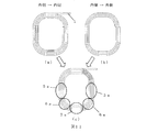
実施例として、図1(c)に示すような平角電線1の円弧形状を変化させる部分を限定した円形多段コイルについて説明する。図1(c)に示すコイルは、同一円弧部分10cと、変化させる円弧部分11cの2箇所から成るディスク状に平角電線1をディスク巻きし、積層させたコイルである。
As an embodiment, a circular multi-stage coil in which a portion where the arc shape of the flat
まず、図1(a)に示すように、平角電線1を外側から内側に順次径方向に隙間を詰めながらディスク状に成形する。即ち、平角電線1は、最外周の同一円弧形状(同一の曲率半径を有する)に限定した範囲10aで成形される。この例では、範囲10aは全体の4分の3に相当する270度の角度範囲である。次の範囲11aで平角電線1が最外周の円弧より線幅分内側になるように円弧成形する。範囲11aは、この例では残る4分の1に相当する90度の角度範囲である。範囲11aにおいては、当該限定範囲の開始点から終了点までに、平角電線1の円弧は、既に巻かれた平角電線1の内側になるように成形すれば良い。当該円弧の曲率半径は、開始点では範囲10aでの曲率半径と同じであるが、終了点では平角電線1の幅だけ短くなっている。この動作を所定列数繰り返すことで、平角電線1はディスク巻きされる。
First, as shown in FIG. 1 (a), the flat
その後、図1(b)に示すように、この逆動作で内側から外側に順次径方向に隙間を詰め、範囲10bでは同一円弧形状(同一の曲率半径を有する)であり、次の範囲11bで平角電線1が最外周の円弧より線幅分内側になるように円弧成形する。これを繰り返して平角電線1をディスク巻きしてディスク状に形成し、全ての段において,範囲10a,10bについてそれぞれ同一の円弧形状している部分を揃えながら積層することで、円形多段コイルが完成する。
Thereafter, as shown in FIG. 1 (b), the reverse operation sequentially fills the gaps in the radial direction from the inside to the outside, and the
このように、従来のように、平角電線1の円弧成形を1周巻く間に徐々に変化させ、最終的に電線幅分を変化させるのではなく、この発明では、段毎に、円弧成形を変化させる部分(範囲11a,11b)を限定することにより、平角電線が外側から内側に、又は内側から外側と異なる円弧形状に変化している部分(範囲11a,11b)と、全ての段において同一の円弧形状している部分(範囲10a,10b)とが発生し、このうち、全ての段において同一の円弧形状している部分(範囲10a,10b)は、上下のディスク間で丁度重なり、容易に平角電線1を揃え、整列させることが可能である。揃えることが従来困難であった、外側から内側へ、或いは内側から外側へと異なる円弧形状に変化している部分についても、同一の円弧形状している部分(範囲10a,10b)を揃えることにより、必然的に揃うようになり、容易に平角電線1を積層することが可能である。
As described above, instead of gradually changing the arc forming of the flat
本発明によれば、円形多段コイルの巻線において、平角電線1を円弧状に成形したものを容易に揃え、積層することが容易となり、量産生産することが可能である。更に、図12示した徐々に平角電線1の円弧形状を変化させる方法では、4列を想定した円形多段コイルであるが、コイルの一部分の列12bを4列にすると、コイルの他の部分での列12aが5列となる。しかし、本発明の巻線方法(図1(c))では、列13a、列13b共に4列となり、平角電線1の占積率が向上するため、材料費低減、コイル特性向上にもつながる。
According to the present invention, in the winding of a circular multi-stage coil, the flat
図2には、この発明による別の円形多段コイル(及びそ)の巻線方法の別の実施例が示されている。図2に示す実施例においては、範囲11aの開始点と終了点との間は直線で結ばれた範囲14a,14b,14cとなっている(図2(c))。この実施例では、コイルの全体の形状がD型となっており、その分、平角電線1の占積率が悪く、コイル特性の悪化が考えられる。しかしながら、実際の特性上、特に問題なければ、実現可能である。また、この実施例では、平角電線1が円弧、直線、円弧、直線、というように繰り返されることになり、自動連続成形には不向きである。
FIG. 2 shows another embodiment of another circular multi-stage coil (and its winding method) according to the present invention. In the embodiment shown in FIG. 2, the
図3には、この発明による別の円形多段コイル(及びそ)の巻線方法の更に別の実施例が示されている。図3に示す実施例においては、範囲11aの開始点と終了点との間は多角形の直線で結ばれた範囲15a,15b,15cとなっている(図3(c))。この実施例では、実施例2よりはコイルの全体形状が円形に近くなり、平角電線1の占積率が向上し、コイルの特性も改善され、実現可能である。しかし、実施例2と同様に、平角電線1が円弧、直線、直線、円弧、直線、直線、というように繰り返されることになり、自動連続成形には不向きである。
FIG. 3 shows still another embodiment of another circular multi-stage coil (and its winding method) according to the present invention. In the embodiment shown in FIG. 3, the
図4には、この発明による別の円形多段コイル(及びそ)の巻線方法の更に別の実施例が示されている。図4に示す実施例においては、範囲11aの開始点と終了点との間は多分割の円弧で結ばれた範囲となっている。この範囲は、外側から内側へディスク巻きをする場合には、範囲11a−1と範囲11a−2で2分割の円弧となっており、内側から外側へディスク巻きをする場合には、範囲11b−1と範囲11b−2で2分割の円弧となっている。この実施例では、コイル形状もほぼ円形となり、占積率を落とすこと無く、円形多段コイルの製作が可能である。更に、多分割された円弧同士を接線で結ぶ様な軌跡を描くことにより、より占積率の良いコイル形状になる。また、平角電線1が円弧、円弧、円弧、というように繰り返されることになり、自動連続成形が可能である。
範囲11aを2分割し、円弧を接点でつながるような軌跡とした時の計算式を以下に示す。ただし、R1,R2は分割円弧の接続前後のそれぞれの半径であり、Rは円弧R1についてのコイル中心(図の原点位置)からの図示のような基準半径であり、Aは平形電線の電線幅である。また、yはコイル中心(図の原点位置)からの半径R1,R2で定められる円弧中心までの距離である。図4(a)及び図4(b)において、それぞれ(1)〜(3)、及び(11)〜(13)が成立し、これらの式から、半径R1,R2及び距離yを、それぞれ(5)〜(7)及び(15)〜(17)に示すように、基準半径R及び電線幅Aで表すことができる。
図4(a)の場合、
45°の線上において R2=R1+y√2 ・・・(1)
90°の線上において −A+R=R2−y ・・・(2)
0°の線上において R=R1+y ・・・(3)
(1)と(2)からR2を消去すると、
−A+R=R1+y(√2−1)・・・(4)
(3)と(4)からyを消去すると、
(2−√2)R=A+(2−√2)R1
よって、 R1=R−(2+√2)×A/2 ・・・(5)
R2=R+(√2)×A/2 ・・・(6)
y=R−R1=(2+√2)×A/2・・・(7)
図4(b)の場合、
45°の線上において R2=R1+y√2 ・・・(11)
90°の線上において A+R=R1+y ・・・(12)
0°の線上において R2=R+y ・・・(13)
(1)と(3)からR2を消去すると、
y=(√2+1)(R−R1)・・・(14)
(2)と(4)からyを消去すると、
A+R=R1+(√2+1)(R−R1)
よって、 R1=R−(√2)×A/2 ・・・(15)
R2=R+(2+√2)×A/2・・・(16)
y=A+R−R1=(2+√2)×A/2・・・(17)
FIG. 4 shows still another embodiment of another circular multi-stage coil (and its winding method) according to the present invention. In the embodiment shown in FIG. 4, the start point and end point of the
The calculation formula when the
In the case of FIG.
On the 45 ° line R 2 = R 1 + y√2 (1)
On the 90 ° line -A + R = R 2 -y (2)
On the 0 ° line, R = R 1 + y (3)
If R 2 is deleted from (1) and (2),
-A + R = R 1 + y (√2-1) (4)
If y is deleted from (3) and (4),
(2-√2) R = A + (2-√2) R 1
Therefore, R 1 = R− (2 + √2) × A / 2 (5)
R 2 = R + (√2) × A / 2 (6)
y = R−R 1 = (2 + √2) × A / 2 (7)
In the case of FIG.
On the line of 45 °, R 2 = R 1 + y√2 (11)
On the 90 ° line A + R = R 1 + y (12)
On the 0 ° line R 2 = R + y (13)
If R 2 is deleted from (1) and (3),
y = (√2 + 1) (R−R 1 ) (14)
If y is deleted from (2) and (4),
A + R = R 1 + (√2 + 1) (R−R 1 )
Therefore, R 1 = R− (√2) × A / 2 (15)
R 2 = R + (2 + √2) × A / 2 (16)
y = A + R−R 1 = (2 + √2) × A / 2 (17)
範囲11aの開始点と終了点との間の円弧を徐々に変化させて結ぶ方法がある。この実施例でもコイルの全体形状はほぼ円形となり、占積率を落とすこと無く、円形多段コイルの製作が可能である。また、平角電線1が円弧であるため自動連続成形が可能である。
There is a method in which the arc between the start point and end point of the
本発明はモールド変圧器の、円形多段コイル、又は直線部分が短い矩形多段コイルの巻線において、円弧状に成形した平角電線の積層を容易することで、生産性を向上させ量産が可能となる。更に、平角電線の占積率が向上し材料費低減、コイル特性向上となる、円形多段コイル、又は、直線部分が短い矩形多段コイルの巻線方法に関する。 The present invention makes it possible to improve the productivity and mass production by facilitating the lamination of a rectangular electric wire formed into an arc shape in a winding of a circular multi-stage coil or a rectangular multi-stage coil having a short straight portion of a molded transformer. . Further, the present invention relates to a winding method of a circular multistage coil or a rectangular multistage coil having a short straight line portion, which improves the space factor of a rectangular electric wire and reduces material cost and coil characteristics.
1:平角電線 2:平角電線成形部
3:成形した平角電線 4:平角電線積層部
5:直線部 5a:直線部(平面図)
6:コーナー部 6a:コーナー部(平面図)
7:幅ガイドローラ 8:圧延ローラ
9:成形ローラ
10a:同一円弧形状部(外側→内側)
10b:同一円弧形状部(内側→外側)
10c:同一円弧形状部(外側→内側、内側→外側)
11a:円弧を変化させる部分(外側→内側)
11a−1:変化させる円弧1(外側→内側)
11a−2:変化させる円弧2(外側→内側)
11b:円弧を変化させる部分(内側→外側)
11b−1:変化させる円弧1(内側→外側)
11b−2:変化させる円弧2(内側→外側)
11c:円弧を変化させる部分(外側→内側、内側→外側)
12a:平角電線の列数 12b:平角電線の列数
13a:平角電線の列数 13b:平角電線の列数
14a:平角電線を直線で変化(外側→内側)
14b:平角電線を直線で変化(内側→外側)
14c:平角電線を直線で変化(内側→外側、外側→内側)
15a:平角電線を多角形で変化(外側→内側)
15b:平角電線を多角形で変化(内側→外側)
15c:平角電線を多角形で変化(内側→外側、外側→内側)
1: flat electric wire 2: flat electric wire forming part 3: formed flat electric wire 4: flat electric wire laminated part 5: straight part 5a: straight part (plan view)
6: Corner part 6a: Corner part (plan view)
7: Width guide roller 8: Rolling roller 9: Forming roller 10a: Same arc shape part (outer side → inner side)
10b: Same arc shape part (inside → outside)
10c: Same arc shape part (outer side → inner side, inner side → outer side)
11a: A part to change the arc (outside to inside)
11a-1:
11a-2:
11b: A part to change the arc (inside to outside)
11b-1:
11b-2:
11c: A part to change the arc (outside → inside, inside → outside)
12a: Number of rows of flat
14b: Straight wire is changed in a straight line (inside to outside)
14c: Straight wire is changed in a straight line (inside → outside, outside → inside)
15a: Change the rectangular electric wire into a polygon (outside → inside)
15b: The rectangular electric wire is changed to a polygon (inside to outside)
15c: Change the rectangular electric wire into a polygon (inside → outside, outside → inside)
Claims (10)
ディスク巻きされる前記平角電線を、前記ディスクの周方向で見て、円弧形状を変化させない角度範囲と前記線幅分だけ円弧形状を変化させた角度範囲とに区分し、
前記各ディスクの前記円弧形状を変化させない角度範囲同士及び前記円弧形状を変化させた角度範囲同士を揃えて互いに積上げたことから成ることを特徴とする円形多段コイルの巻線方法。 In a winding method of a circular multi-stage coil in which a rectangular electric wire is wound around a disk by changing the radial direction by the line width from the outer periphery to the inner periphery, and then from the inner periphery to the outer periphery, and this disk is repeatedly stacked .
It said rectangular electric wire is disk winding, viewed in the circumferential direction of the disk, divided into a range of angles varying arc shape and an angle range that does not change the arc shape only the line width of,
Winding method of a circular multi-stage coil, characterized in that consists of aligning the angular range between of varying the arc shape do not change the angle range between and the arc shape of each disc was stacked with each other.
前記平角電線の前記円弧形状を変化させた角度範囲は、曲率半径を徐々に変化させた円弧形状で成ることを特徴とする円形多段コイルの巻線方法。 In the winding method of the circular multistage coil according to claim 1,
The method of winding a circular multistage coil, wherein the angle range of the flat electric wire in which the arc shape is changed is an arc shape in which the radius of curvature is gradually changed.
前記平角電線の前記円弧形状を変化させた角度範囲は、直線形状で成ることを特徴とする円形多段コイルの巻線方法。 In the winding method of the circular multistage coil according to claim 1,
The angular range of the arc shape is changed in the rectangular electric wire is winding method of a circular multi-stage coil, characterized by comprising a linear shape.
前記平角電線の前記円弧形状を変化させた角度範囲は、径方向外側に凸となる折れ線形状で成ることを特徴とする円形多段コイルの巻線方法。 In the winding method of the circular multistage coil according to claim 1,
The arcuate shape of the angular range is changed, the winding method of a circular multi-stage coil, characterized by comprising a polygonal line shape which is convex in the radially outer side of the rectangular electric wire.
前記平角電線の前記円弧形状を変化させた角度範囲は、複数の曲率半径の円弧形状を繋げて成ることを特徴とする円形多段コイルの巻線方法。 In the winding method of the circular multistage coil according to claim 1,
The angular range of the arc shape is changed in the rectangular electric wire is winding method of a circular multi-stage coil, characterized by comprising connecting a plurality of radii of curvature of the arc shape.
ディスク巻きされる前記平角電線を、前記ディスクの周方向で見て、円弧形状を変化させない角度範囲と前記線幅分だけ円弧形状を変化させた角度範囲とに区分し、
前記各ディスクの前記円弧形状を変化させない角度範囲同士及び前記円弧形状を変化させた角度範囲同士を揃えて互いに積上げたことから成ることを特徴とする円形多段コイル。 In a circular multi-stage coil formed by winding a rectangular electric wire from the outer periphery to the inner periphery, then changing the radial direction by the line width from the inner periphery to the outer periphery, and repeating this to pile up the disk in a plurality of stages .
It said rectangular electric wire is disk winding, viewed in the circumferential direction of the disk, divided into a range of angles varying arc shape and an angle range that does not change the arc shape only the line width of,
A circular multi-stage coil comprising: an angular range in which the circular arc shape of each disk is not changed and an angular range in which the circular arc shape is changed are aligned and stacked on each other.
前記平角電線の前記円弧形状を変化させた角度範囲は、曲率半径を徐々に変化させた円弧形状で成ることを特徴とする円形多段コイル。 The circular multistage coil according to claim 6,
The circular multi-stage coil according to claim 1, wherein an angle range in which the arc shape of the flat electric wire is changed is an arc shape in which a radius of curvature is gradually changed.
前記平角電線の前記円弧形状を変化させた角度範囲は、直線形状で成ることを特徴とする円形多段コイル。 The circular multistage coil according to claim 6,
The angular range of the arc shape is changed in the rectangular electric wire is circular multi-stage coil, characterized by comprising a linear shape.
前記平角電線の前記円弧形状を変化させた角度範囲は、径方向外側に凸となる折れ線形状で成ることを特徴とする円形多段コイル。 The circular multistage coil according to claim 6,
The circular multi-stage coil is characterized in that an angle range obtained by changing the arc shape of the flat electric wire is a polygonal line shape protruding outward in the radial direction.
前記平角電線の前記円弧形状を変化させた角度範囲は、複数の曲率半径の円弧形状を繋げて成ることを特徴とする円形多段コイル。 Oite circular multistage coil according to claim 6,
An angular range in which the arc shape of the flat electric wire is changed is formed by connecting arc shapes having a plurality of curvature radii.
Priority Applications (1)
| Application Number | Priority Date | Filing Date | Title |
|---|---|---|---|
| JP2008237564A JP5191846B2 (en) | 2008-09-17 | 2008-09-17 | Circular multi-stage coil and winding method thereof |
Applications Claiming Priority (1)
| Application Number | Priority Date | Filing Date | Title |
|---|---|---|---|
| JP2008237564A JP5191846B2 (en) | 2008-09-17 | 2008-09-17 | Circular multi-stage coil and winding method thereof |
Publications (2)
| Publication Number | Publication Date |
|---|---|
| JP2010073777A JP2010073777A (en) | 2010-04-02 |
| JP5191846B2 true JP5191846B2 (en) | 2013-05-08 |
Family
ID=42205318
Family Applications (1)
| Application Number | Title | Priority Date | Filing Date |
|---|---|---|---|
| JP2008237564A Active JP5191846B2 (en) | 2008-09-17 | 2008-09-17 | Circular multi-stage coil and winding method thereof |
Country Status (1)
| Country | Link |
|---|---|
| JP (1) | JP5191846B2 (en) |
Family Cites Families (9)
| Publication number | Priority date | Publication date | Assignee | Title |
|---|---|---|---|---|
| JPS5937487A (en) * | 1982-08-26 | 1984-02-29 | 株式会社東芝 | Magnetic field coil for nuclear fusion device |
| JPH0382104A (en) * | 1989-08-25 | 1991-04-08 | Amorufuasu Denshi Device Kenkyusho:Kk | Magnetic thin film transformer |
| JPH0722255A (en) * | 1993-06-17 | 1995-01-24 | Amorphous Denshi Device Kenkyusho:Kk | Magnetic thin film transformer |
| JP3642352B2 (en) * | 1995-04-27 | 2005-04-27 | 株式会社安川電機 | Rotating transformer |
| JP3194520B2 (en) * | 1998-04-06 | 2001-07-30 | 日特エンジニアリング株式会社 | Winding device |
| JP3488868B2 (en) * | 2001-03-05 | 2004-01-19 | Tdk株式会社 | Planar coils and transformers |
| JP2004193249A (en) * | 2002-12-10 | 2004-07-08 | Sanken Electric Co Ltd | Coil device and its manufacturing method |
| JP2007012969A (en) * | 2005-07-01 | 2007-01-18 | Shinji Kudo | Laminated coil and method for manufacturing the same |
| JP4764276B2 (en) * | 2006-07-14 | 2011-08-31 | 日特エンジニアリング株式会社 | Coil winding method and apparatus |
-
2008
- 2008-09-17 JP JP2008237564A patent/JP5191846B2/en active Active
Also Published As
| Publication number | Publication date |
|---|---|
| JP2010073777A (en) | 2010-04-02 |
Similar Documents
| Publication | Publication Date | Title |
|---|---|---|
| JP5155732B2 (en) | Multi-stage coil for transformer, and winding method and apparatus for manufacturing the same | |
| US9570966B2 (en) | Method for manufacturing a coil | |
| CN103370856B (en) | Stator of rotating electric machine and winding method thereof | |
| US8373532B2 (en) | Coil | |
| HK1219354A1 (en) | Stator or rotor for electrical machines and method for manufacturing same | |
| CN101346782B (en) | Winding method and coil unit | |
| WO2012101812A1 (en) | Manufacturing method for helical core for rotating electrical machine and manufacturing device for helical core for rotating electrical machine | |
| US20140015368A1 (en) | Stator, method for manufacturing stator, and flat conductor for winding | |
| JP2013099084A (en) | Flat wire winding structure | |
| JP5683045B2 (en) | Winding forming apparatus and winding forming method | |
| US20100193506A1 (en) | Litz wire coil | |
| JP2003086438A (en) | Air-core coil and coil device, and method for manufacturing the same | |
| CN104335304B (en) | Coil winding method and transformer | |
| JP2005327834A (en) | Coil and its manufacturing method | |
| EP2555392A2 (en) | Segmented rotor and stator lamination cores | |
| JP5191846B2 (en) | Circular multi-stage coil and winding method thereof | |
| KR101587706B1 (en) | Laminated Stator Core with Split Yoke | |
| JP5860767B2 (en) | Coil manufacturing method | |
| EP4264784A1 (en) | Stator metal sheet with radial stator teeth and method for manufacturing the stator metal sheet | |
| JP2013251996A (en) | Method for manufacturing coil | |
| JP3996005B2 (en) | Multi-stage coil manufacturing equipment | |
| JP4616652B2 (en) | Coil manufacturing equipment | |
| JP4996359B2 (en) | A meandering annular winding coil forming technique using pre-formed polygonal annular winding | |
| CN109804531A (en) | Stator of rotating electrical machine and method of manufacturing the same | |
| JP2008043108A (en) | Winding method and split stator |
Legal Events
| Date | Code | Title | Description |
|---|---|---|---|
| A621 | Written request for application examination |
Free format text: JAPANESE INTERMEDIATE CODE: A621 Effective date: 20110128 |
|
| A977 | Report on retrieval |
Free format text: JAPANESE INTERMEDIATE CODE: A971007 Effective date: 20120223 |
|
| A131 | Notification of reasons for refusal |
Free format text: JAPANESE INTERMEDIATE CODE: A131 Effective date: 20120327 |
|
| A521 | Request for written amendment filed |
Free format text: JAPANESE INTERMEDIATE CODE: A523 Effective date: 20120518 |
|
| TRDD | Decision of grant or rejection written | ||
| A01 | Written decision to grant a patent or to grant a registration (utility model) |
Free format text: JAPANESE INTERMEDIATE CODE: A01 Effective date: 20130108 |
|
| A61 | First payment of annual fees (during grant procedure) |
Free format text: JAPANESE INTERMEDIATE CODE: A61 Effective date: 20130130 |
|
| R150 | Certificate of patent or registration of utility model |
Ref document number: 5191846 Country of ref document: JP Free format text: JAPANESE INTERMEDIATE CODE: R150 Free format text: JAPANESE INTERMEDIATE CODE: R150 |
|
| FPAY | Renewal fee payment (event date is renewal date of database) |
Free format text: PAYMENT UNTIL: 20160208 Year of fee payment: 3 |