JP5141304B2 - Gas concentration distribution measuring device - Google Patents
Gas concentration distribution measuring device Download PDFInfo
- Publication number
- JP5141304B2 JP5141304B2 JP2008058278A JP2008058278A JP5141304B2 JP 5141304 B2 JP5141304 B2 JP 5141304B2 JP 2008058278 A JP2008058278 A JP 2008058278A JP 2008058278 A JP2008058278 A JP 2008058278A JP 5141304 B2 JP5141304 B2 JP 5141304B2
- Authority
- JP
- Japan
- Prior art keywords
- gas
- surface acoustic
- acoustic wave
- concentration distribution
- gas concentration
- Prior art date
- Legal status (The legal status is an assumption and is not a legal conclusion. Google has not performed a legal analysis and makes no representation as to the accuracy of the status listed.)
- Expired - Fee Related
Links
Images


Classifications
-
- G—PHYSICS
- G01—MEASURING; TESTING
- G01N—INVESTIGATING OR ANALYSING MATERIALS BY DETERMINING THEIR CHEMICAL OR PHYSICAL PROPERTIES
- G01N29/00—Investigating or analysing materials by the use of ultrasonic, sonic or infrasonic waves; Visualisation of the interior of objects by transmitting ultrasonic or sonic waves through the object
- G01N29/02—Analysing fluids
- G01N29/022—Fluid sensors based on microsensors, e.g. quartz crystal-microbalance [QCM], surface acoustic wave [SAW] devices, tuning forks, cantilevers, flexural plate wave [FPW] devices
-
- G—PHYSICS
- G01—MEASURING; TESTING
- G01N—INVESTIGATING OR ANALYSING MATERIALS BY DETERMINING THEIR CHEMICAL OR PHYSICAL PROPERTIES
- G01N29/00—Investigating or analysing materials by the use of ultrasonic, sonic or infrasonic waves; Visualisation of the interior of objects by transmitting ultrasonic or sonic waves through the object
- G01N29/02—Analysing fluids
- G01N29/032—Analysing fluids by measuring attenuation of acoustic waves
-
- G—PHYSICS
- G01—MEASURING; TESTING
- G01N—INVESTIGATING OR ANALYSING MATERIALS BY DETERMINING THEIR CHEMICAL OR PHYSICAL PROPERTIES
- G01N2291/00—Indexing codes associated with group G01N29/00
- G01N2291/02—Indexing codes associated with the analysed material
- G01N2291/021—Gases
- G01N2291/0215—Mixtures of three or more gases, e.g. air
-
- G—PHYSICS
- G01—MEASURING; TESTING
- G01N—INVESTIGATING OR ANALYSING MATERIALS BY DETERMINING THEIR CHEMICAL OR PHYSICAL PROPERTIES
- G01N2291/00—Indexing codes associated with group G01N29/00
- G01N2291/04—Wave modes and trajectories
- G01N2291/042—Wave modes
- G01N2291/0423—Surface waves, e.g. Rayleigh waves, Love waves
Landscapes
- Physics & Mathematics (AREA)
- Acoustics & Sound (AREA)
- Health & Medical Sciences (AREA)
- Life Sciences & Earth Sciences (AREA)
- Chemical & Material Sciences (AREA)
- Analytical Chemistry (AREA)
- Biochemistry (AREA)
- General Health & Medical Sciences (AREA)
- General Physics & Mathematics (AREA)
- Immunology (AREA)
- Pathology (AREA)
- Investigating Or Analyzing Materials By The Use Of Ultrasonic Waves (AREA)
- Sampling And Sample Adjustment (AREA)
Description
この発明は、空間中のガスの濃度分布を計測するガス濃度分布計測装置に関係している。 The present invention relates to a gas concentration distribution measuring apparatus for measuring a gas concentration distribution in a space.
従来から、安価で携帯可能であって空間中のガスの濃度分布をより精密により早く計測可能なガス濃度分布計測装置が求められている。 Conventionally, there has been a demand for a gas concentration distribution measuring device that is inexpensive and portable and that can measure the concentration distribution of gas in a space more precisely and quickly.
現在、半導体式ガス検知器を使用して片手で持つことが可能な大きさで所定のガスの濃度を測定可能な種々のガス濃度分布計測装置が知られている。種々の従来の半導体式ガス検知器の中には、所定のガスの濃度を測定するのに比較的時間が掛かるものがあるし、短時間で所定のガスの濃度を測定することが出来るものもある。 At present, there are known various gas concentration distribution measuring apparatuses capable of measuring the concentration of a predetermined gas in a size that can be held with one hand using a semiconductor gas detector. Among various conventional semiconductor gas detectors, there are those that take a relatively long time to measure the concentration of a predetermined gas, and those that can measure the concentration of a predetermined gas in a short time. is there.
所定のガスの濃度を測定するのに比較的時間が掛かる半導体式ガス感知器を1個のみ使用しているガス濃度分布計測装置を1台のみ使用して空間中の所定のガスの濃度分布を測定するには多くの時間が掛かるし、測定の間に空間中の所定のガスの濃度分布が大きく変わる可能性が非常に大きい。 Using only one gas concentration distribution measuring device that uses only one semiconductor-type gas sensor that takes a relatively long time to measure the concentration of a predetermined gas, the concentration distribution of the predetermined gas in the space can be determined. The measurement takes a lot of time, and it is highly possible that the concentration distribution of a predetermined gas in the space will change greatly during the measurement.
所定のガスの濃度を測定するのに比較的時間が掛かる半導体式ガス検知器を1個のみ使用したガス濃度分布計測装置を複数台使用すれば、空間中の所定のガスの濃度分布を測定するのに要する時間を大きく減少させることは出来る。しかしながら、それでも測定の間に空間中の所定のガスの濃度分布が変わる可能性が大きい。また、複数台のガス濃度分布計測装置を使用するので、測定の為の準備作業が煩雑である。 If a plurality of gas concentration distribution measuring devices using only one semiconductor gas detector that takes a relatively long time to measure the concentration of a predetermined gas are used, the concentration distribution of the predetermined gas in the space is measured. The time required for this can be greatly reduced. However, there is still a high possibility that the concentration distribution of the predetermined gas in the space changes during the measurement. In addition, since a plurality of gas concentration distribution measuring devices are used, the preparation work for measurement is complicated.
そして、空間中の複数の種類のガスの濃度分布を測定するには、空間中の特定の種類のガスの濃度分布を測定するために特定の種類のガスの濃度を測定する為の半導体式ガス検知器を1個のみ使用したガス濃度分布計測装置が複数台必要となるので、濃度測定が必要となるガスの種類の数に比例して、さらに多くのガス濃度分布計測装置が必要となる。 In order to measure the concentration distribution of a plurality of types of gas in the space, a semiconductor type gas for measuring the concentration of a specific type of gas in order to measure the concentration distribution of the specific type of gas in the space. Since a plurality of gas concentration distribution measuring devices using only one detector are required, more gas concentration distribution measuring devices are required in proportion to the number of types of gases that require concentration measurement.
複数の種類のガスの濃度を測定するための複数の種類の半導体式ガス検知器を複数個使用したガス濃度分布計測装置を使用しても、空間中の複数の種類のガスの濃度分布を測定するには上述した如きガス濃度分布計測装置を複数個使用しなければならないので、測定の為の準備作業が依然として煩雑である。しかも所定のガスの濃度を測定するのに比較的時間が掛かる半導体式ガス検知器を使用していれば、測定の間に空間中の複数のガスの濃度分布が変わる可能性が大きい。 Measures the concentration distribution of multiple types of gas in space even when using a gas concentration distribution measuring device that uses multiple types of semiconductor gas detectors to measure the concentration of multiple types of gas In order to do this, a plurality of gas concentration distribution measuring devices as described above must be used, so that the preparation work for measurement is still complicated. Moreover, if a semiconductor gas detector that takes a relatively long time to measure the concentration of a predetermined gas is used, the concentration distribution of a plurality of gases in the space is likely to change during the measurement.
短時間で所定のガスの濃度を測定することが出来る半導体式ガス感知器は、所定のガスの濃度変化に従い酸化錫の電気抵抗値が変化することを利用している。しかしながらこの半導体式ガス感知器は所定のガスの濃度の低下に対しては応答に時間がかかる。また、このような半導体式ガス感知器を使用する場合には、酸化錫を高温に加熱する必要がある。従って、このような半導体式ガス感知器を可燃性のガスを含む複数種類のガスの濃度の測定には使用できない。さらにこのような半導体式ガス感知器を可燃性のガスを含まない複数種類のガスの濃度の測定に使用する場合でも、高温に加熱された酸化錫がその周囲のガスに対流を生じさせるので、複数の種類のガスの濃度分布の測定の精度に限界がある。 A semiconductor gas sensor capable of measuring the concentration of a predetermined gas in a short time utilizes the fact that the electric resistance value of tin oxide changes according to the concentration change of the predetermined gas. However, this semiconductor gas sensor takes time to respond to a decrease in the concentration of a predetermined gas. Further, when such a semiconductor gas sensor is used, it is necessary to heat the tin oxide to a high temperature. Therefore, such a semiconductor gas sensor cannot be used for measuring concentrations of a plurality of types of gases including flammable gases. Furthermore, even when such a semiconductor gas sensor is used to measure the concentration of a plurality of types of gases that do not contain flammable gases, tin oxide heated to a high temperature causes convection in the surrounding gas. There is a limit to the accuracy of measuring the concentration distribution of multiple types of gases.
この発明は上記事情の下でなされ、この発明の目的は、安価で携帯可能であって上述した従来のガス濃度分布計測装置に比べ空間中のガスの濃度分布をより精密により早く計測可能なガス濃度分布計測装置を提供することである。 The present invention has been made under the above circumstances, and an object of the present invention is to provide a gas that is cheap and portable and can measure the concentration distribution of gas in the space more precisely and quickly than the conventional gas concentration distribution measuring apparatus described above. It is to provide a concentration distribution measuring device.
上述したこの発明の目的を達成する為に、この発明に従ったガス濃度分布計測装置は:夫々が所定のガスの濃度を測定する複数のガス検知器を所定の間隔の複数の位置に支持していて、前記複数の位置から延出した通気孔が形成されているとともに、前記通気孔を介して前記複数の位置から前記所定のガスを吸引する為に前記通気孔の延出端に吸気ユニットが接続されている直線状の支持体を備えていて、複数の前記ガス検知器同士の相対位置を保持したまま移動するガス検知部と;前記ガス検知部の複数のガス検知器の位置情報を測定するガス検知器位置情報測定部と;前記ガス検知部の複数のガス検知器が測定したガス濃度の測定値と、複数のガス検知器がガス濃度の測定を終了した時点でガス検知器位置情報測定部により測定された複数のガス検知器の位置情報と、が入力され、前記ガス濃度の測定値と前記ガス検知器の位置情報とを基に、前記ガス検知部が移動した空間における前記所定のガスの濃度の分布を表示するガス濃度分布表示ユニットと;を備えており、前記ガス検知器が、球形状の一部により円環状に連続しており弾性表面波を周回させる弾性表面波周回路を少なくとも1つ含む弾性表面波素子を含む、ことを特徴としている。 In order to achieve an object of the present invention described above, the present invention gas concentration distribution measuring apparatus according to the: a plurality of gas detectors respectively to measure the concentration of a given gas is supported on a plurality of positions of a predetermined distance In addition, a ventilation hole extending from the plurality of positions is formed, and an intake unit is provided at an extension end of the ventilation hole to suck the predetermined gas from the plurality of positions through the ventilation hole. A gas detector that includes a linear support to which the gas detectors are connected and moves while maintaining the relative positions of the gas detectors; and positional information of the gas detectors of the gas detectors. A gas detector position information measuring unit to be measured; a gas concentration measurement value measured by a plurality of gas detectors of the gas detection unit, and a gas detector position when the plurality of gas detectors finish measuring the gas concentration The data measured by the information measurement unit The position information of the gas detector is input, and based on the measured value of the gas concentration and the position information of the gas detector, the distribution of the concentration of the predetermined gas in the space where the gas detector moves is calculated. A gas concentration distribution display unit for displaying , and the gas detector includes an elastic member including at least one surface acoustic wave circuit that circulates a surface acoustic wave that is continuous in an annular shape with a part of a spherical shape. It includes a surface wave element .
上述した如く構成されたことを特徴とするこの発明に従ったガス濃度分布計測装置では、夫々が所定のガスの濃度を測定する複数のガス検知器を所定の間隔の複数の位置に支持していて、前記複数の位置から延出した通気孔が形成されているとともに、前記通気孔を介して前記複数の位置から前記所定のガスを吸引する為に前記通気孔の延出端に吸気ユニットが接続されている直線状の支持体を備えているガス検知部が複数の前記ガス検知器同士の相対位置を保持したまま移動するとともに、ガス検知器位置情報測定部が、前記ガス検知部の複数のガス検知器の位置情報を測定する。 In the gas concentration distribution measuring device according to the invention which is characterized in that it is composed as described above, it supported the plurality of gas detectors respectively to measure the concentration of a predetermined gas in a plurality of positions of a predetermined distance In addition, a vent hole extending from the plurality of positions is formed, and an intake unit is provided at an extension end of the vent hole for sucking the predetermined gas from the plurality of positions through the vent hole. A gas detector having a connected linear support moves while maintaining a relative position between the plurality of gas detectors, and a gas detector position information measuring unit includes a plurality of gas detectors. The position information of the gas detector is measured.
上述した如く構成されたことを特徴とするこの発明に従ったガス濃度分布計測装置ではさらに、前記ガス検知部の複数のガス検知器が測定したガス濃度の測定値と、複数のガス検知器がガス濃度の測定を終了した時点でガス検知器位置情報測定部により測定された複数のガス検知器の位置情報と、が入力されたガス濃度分布表示ユニットが、前記ガス濃度の測定値と前記ガス検知器の位置情報とを基に、前記ガス検知部が移動した空間における前記所定のガスの濃度の分布を表示する。 In the gas concentration distribution measuring apparatus according to the present invention configured as described above, the gas concentration measurement values measured by the plurality of gas detectors of the gas detector and the gas detectors are further provided. The gas concentration distribution display unit to which the position information of the plurality of gas detectors measured by the gas detector position information measuring unit when the measurement of the gas concentration is completed is input to the measured value of the gas concentration and the gas Based on the position information of the detector, the distribution of the concentration of the predetermined gas in the space in which the gas detector moves is displayed.
従って、この発明に従ったガス濃度分布計測装置は、安価で携帯可能であって、前述した従来のガス濃度分布計測装置に比べ空間中のガスの濃度分布をより精密により早く計測可能である。 Therefore, the gas concentration distribution measuring apparatus according to the present invention is inexpensive and portable, and can measure the gas concentration distribution in the space more precisely and quickly than the conventional gas concentration distribution measuring apparatus described above.
[第1の実施の形態]
最初に、図1乃至図4を参照しながらこの発明の第1の実施の形態に従ったガス濃度分布計測装置10について説明する。
[First Embodiment]
First, a gas concentration
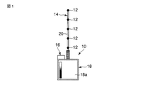
図1中に、この発明の第1の実施の形態に従ったガス濃度分布計測装置10の全体の正面が概略的に示されている。
FIG. 1 schematically shows the front of the entire gas concentration
ガス濃度分布計測装置10は:相互に異なった複数の位置における所定のガスの濃度を測定する複数のガス検知器12を含むガス検知部14と;複数のガス検知器12の位置情報を測定するガス検知器位置情報測定部16と;そして、ガス検知部14の複数のガス検知器12が測定したガス濃度の測定値と、複数のガス検知器12がガス濃度の測定を終了した時点でガス検知器位置情報測定部14により測定された複数のガス検知器12の位置情報と、が入力され、これらガス濃度の測定値とこれらガス検知器12の位置情報とを基に、少なくとも2次元空間における所定のガス濃度の分布を表示するガス濃度分布表示ユニット18と;を備えている。
The gas concentration
この実施の形態において複数のガス検知器12は、直線状の棒状の支持体20上に所定の間隔(この実施の形態では、所定の等間隔)に支持されていて、棒状の支持体20の一端部がガス濃度分布表示ユニット18の外装ハウジングの所定の位置に固定されている。
In this embodiment, the plurality of
ガス検知器位置情報測定部16もまた、ガス濃度分布表示ユニット18の外装ハウジングに固定されている。ガス濃度分布表示ユニット18は、外装ハウジングの外表面に露出した表示装置18a、この実施の形態では液晶表示装置、を含んでいる。
The gas detector position
ガス検知器位置情報測定部16は、図示しない公知の加速度センサ及び角速度センサの少なくともいずれか一方を備えており、この実施の形態では図示しない公知の加速度センサ及び角速度センサの両方を備えている。加速度センサ及び角速度センサの夫々は少なくともX軸とY軸方向の2方向に作用可能であり、好ましくはさらにZ軸方向を加えた3方向に作用可能である。
The gas detector position
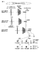
ガス検知器12は、図2中に拡大して示されている如く、球形状の一部により円環状に連続しており弾性表面波を周回させる弾性表面波周回路22aを少なくとも1つ含む弾性表面波素子22を含む。
The
このような弾性表面波素子22は公知である。弾性表面波素子22はその表面に沿い弾性表面波を励起できるとともに所定の方向に弾性表面波を伝搬可能に構成された基材22bを含んでいる。基材22bは、弾性表面波を励起させることが出来ず伝搬させることが出来ない材料で球形状の一部により円環状に連続している表面領域を含む形状(例えば、球形状又は樽形状)に形成された本体の上記表面領域に弾性表面波励起伝搬材料(例えば、圧電材料)を付着させることにより形成することが出来るし、弾性表面波を励起させることが出来るとともに球形状の一部により円環状に連続している表面領域に弾性表面波を伝搬可能な材料(例えば、水晶やランガサイト)により形成することが出来る。
Such a surface
現在では、上記表面領域の直径が3mm程度の曲面を持つ基材22bが使用可能になっている。
At present, the
水晶やランガサイトは、それらを加工して球形状の一部により円環状に連続している表面領域を含む形状(例えば、球形状又は樽形状)に形成する際に、それらの結晶面が上記表面領域に沿い延出するよう加工することにより、上記結晶面が上記表面領域に露出した線に沿い弾性表面波を非常に良好に伝搬させることが出来ることが分かっている。 When crystal or langasite is processed into a shape including a surface region that is continuous in an annular shape by a part of a spherical shape (for example, a spherical shape or a barrel shape), the crystal plane is It has been found that by processing to extend along the surface region, surface acoustic waves can be propagated very well along the line where the crystal plane is exposed in the surface region.
弾性表面波周回路22aには、弾性表面波励起要素としてこの実施の形態ではすだれ状電極22cが載置されている。すだれ状電極22cに、高周波バースト電流を負荷することにより弾性表面波周回路22aに沿い弾性表面波が励起され、弾性表面波はすだれ状電極22cの複数の枝に対し直交する方向に向かい伝搬される。すだれ状電極22cは、弾性表面波周回路22aを周回した弾性表面波を受信し、その受信強度に対応した信号電圧を発生させる弾性表面波受信要素としても機能する。
In this embodiment, an
すだれ状電極22cは、支持体20の表面に沿い、又は支持体20内を、ガス濃度分布表示ユニット18の外装ハウジングに向かい延出した図示しない電線により、上記外装ハウジングに収容されている図示されていない公知の弾性表面波素子制御部に接続される。上記図示されていない公知の弾性表面波素子制御部は、すだれ状電極22cに弾性表面波の励起の為の高周波電流をバースト状に供給する図示されていない公知の高周波電源と、すだれ状電極22cが受信した弾性表面波の強度に対応して発生した信号電圧を受け入れる図示されていない信号受信回路と、を含んでいる。
The
弾性表面波励起伝搬可能な表面に励起され伝搬される弾性表面波は、通常、所定の方向に向かい伝搬する間に伝搬する方向に対し直交する方向に徐々に拡散してしまいその強度が弱まる。 A surface acoustic wave that is excited and propagated on a surface capable of propagating with a surface acoustic wave normally diffuses gradually in a direction perpendicular to the direction of propagation while propagating in a predetermined direction, and its intensity is weakened.
しかしながら、弾性表面波を励起させ伝搬させることが出来るとともに球形状の一部により円環状に連続している表面領域に沿い上記円環状に連続している方向に向かい弾性表面波を励起させ伝搬させる際に、弾性表面波の周波数や上記表面領域において上記円環状に連続している方向に対し直交する方向の長さ等を所定の条件を満たすように設定することにより、上記表面領域を上記円環状に連続している方向に向かい伝搬する弾性表面波を上記伝搬する方向に対し直交する方向に拡散させることなく伝搬させること出来ることが既に知られている。(例えば、K. Yamanaka, S. Ishikawa, N. Nakaso, N. Takada, D.Y. Sim, T. Mihara, A.Mizukami, I. Satoh, S. Akao and Y. Tsukahara, “Ultramultiple roundtrips of surface acoustic wave on sphere realizing innovation of gas sensors”, IEEE Trans. UFFC, 53 (2006), pp. 793-801を参照)
上記表面領域を上記円環状に連続している方向に向かい伝搬する弾性表面波は、伝搬する方向に対し直交する方向に拡散しないので、その強さを維持したままで上記表面領域を上記円環状に連続している方向に向かい繰り返し理論上は無限に周回することが出来る。
However, the surface acoustic wave can be excited and propagated, and the surface acoustic wave can be excited and propagated along the annularly continuous surface region by a part of the spherical shape toward the annularly continuous direction. In this case, by setting the surface acoustic wave frequency and the length of the surface region in a direction orthogonal to the annular continuous direction so as to satisfy a predetermined condition, the surface region is formed into the circle. It is already known that a surface acoustic wave propagating in a ring-continuous direction can be propagated without diffusing in a direction orthogonal to the propagating direction. (For example, K. Yamanaka, S. Ishikawa, N. Nakaso, N. Takada, DY Sim, T. Mihara, A. Mizukami, I. Satoh, S. Akao and Y. Tsukahara, “Ultramultiple roundtrips of surface acoustic wave on sphere realizing innovation of gas sensors ”, IEEE Trans. UFFC, 53 (2006), pp. 793-801)
The surface acoustic wave propagating in the surface region in a direction continuous to the ring does not diffuse in a direction orthogonal to the direction of propagation, so that the surface region remains in the ring shape while maintaining its strength. Theoretically, it is possible to go around infinitely in the direction that continues.
とはいうものの上記表面領域を伝搬する弾性表面波は、それが伝搬する環境が変わればその速度(即ち、1回の周回に要する時間)や強度を変化させる。特に、上記表面領域にある物質が付着するとその付着量に応じた質量効果により、上記表面領域を伝搬する弾性表面波の速度や強度を大きく変化させる。 However, the surface acoustic wave propagating in the surface region changes its speed (that is, the time required for one round) and intensity if the environment in which it propagates changes. In particular, when a substance in the surface region adheres, the velocity and intensity of the surface acoustic wave propagating through the surface region are greatly changed by a mass effect corresponding to the amount of adhesion.
従って上記環境が変化する前と後で上記表面領域を伝搬する弾性表面波の速度及び/又は強度を比較することにより、上記環境の変化の程度を知ることが出来ることになる。なお、上記表面領域を伝搬している弾性表面波のピックアップは、上記弾性表面波励起要素、この実施の形態ではすだれ状電極22c、により実行可能である。
Therefore, by comparing the speed and / or intensity of the surface acoustic wave propagating through the surface region before and after the environment changes, the extent of the environment change can be known. The pickup of the surface acoustic wave propagating through the surface region can be executed by the surface acoustic wave excitation element, which is the
そして、上記表面領域(この実施の形態では、弾性表面波周回路22a)を伝搬する距離(この実施の形態では、弾性表面波周回路22aを周回する回数)が大きくなればなるほど、上記変化が拡大されて、上記変化を明瞭に、即ち精密に、測定可能になる。
Then, as the distance propagating through the surface region (in this embodiment, the surface
例えば、上記環境中の所定のガスの濃度のみが変化するのであれば、上記環境の変化とは上記所定のガスの濃度の変化であることを意味している。 For example, if only the concentration of a predetermined gas in the environment changes, the environmental change means a change in the concentration of the predetermined gas.
上記環境中の所定のガスの濃度の変化のみをより効率良く正確に測定するのであれば、上記表面領域の少なくとも一部に上記所定のガスにのみ感応するガス感応膜を設ければよい。このようなガス感応膜は、例えば所定のガスのみを吸収又は吸着する物質により構成することが出来、例えば、パラジウム−ニッケル合金は、水素ガスを非常に良く吸着することで知られている。 If only the change in the concentration of the predetermined gas in the environment is to be measured more efficiently and accurately, a gas sensitive film sensitive only to the predetermined gas may be provided on at least a part of the surface region. Such a gas sensitive film can be made of, for example, a substance that absorbs or adsorbs only a predetermined gas. For example, a palladium-nickel alloy is known to adsorb hydrogen gas very well.
なおここでいう弾性表面波とは、固体の表面や固体の表面に隣接してエネルギーを集中して伝搬する弾性波の全てを含んでいる。このような弾性波としては、例えば、レイリー波や、多少エネルギーを上記固体に漏洩しながら伝搬するセザワ波や、SH波や、また上記固体の表面に弾性表面波伝搬可能な膜が存在している場合のみ上記膜中を伝搬するラブ波や、或いは回廊波が知られている。 The surface acoustic wave referred to here includes all of the surface acoustic waves that propagate by concentrating energy adjacent to the solid surface or the solid surface. Examples of such elastic waves include Rayleigh waves, Sezawa waves that propagate while slightly leaking energy to the solid, SH waves, and films that can propagate surface acoustic waves on the surface of the solid. A Love wave or a corridor wave propagating through the film is known only when it is present.
弾性表面波素子22は、弾性表面波が伝搬する弾性表面波周回路22a以外の領域が支持体20の表面の所定の位置に例えば接着剤などの公知の支持手段により支持されている。
In the surface
詳細には、この実施の形態では、支持体20の表面の所定の位置に台座20aが固定されていて、台座20aには弾性表面波素子22の基材22bにおいて弾性表面波周回路22aを除いた領域の一部が着座された凹所20bが形成されている。凹所20bからは支持体20中をガス濃度分布表示ユニット18の外装ハウジングまで延出した通気孔20cが形成されていて、通気孔20cの延出端は上記外装ハウジングの内部に収容されている公知の吸気ユニット20dに接続されている。
Specifically, in this embodiment, a
台座20aにはさらに、凹所20bに着座された弾性表面波素子22の周囲を覆うフィルタ20eが設けられている。フィルタ20eは、気体透過性材料(例えば、多孔性物質)により構成されており、弾性表面波素子22の弾性表面波周回路22aにガスを除く異物、例えば固体物質、が接触するのを防止する。
The
このようなフィルタ20eとしては、例えば日本精線(株)により製造され商品名NAScleanとして販売されているフィルタを使用することが出来る。このフィルタは、微細なステンレス鋼短繊維(直径1μm)を層状に焼結したメタルメンブレンフィルタであり、ガスの透過性を保持しながら0.03μm以上の粒子の完全除去を行なうことが出来る。
As such a
そして、上記公知の吸気ユニット20dは、通気孔20cを介して、台座20a上でフィルタ20eにより囲まれている空間のガスをその周囲のガスと2秒以内に入れ替えることが出来る。即ち、上記公知の吸気ユニット20dは、通気孔20cと協働して、ガス交換要素を構成している。
The known
上記環境中の所定のガスの濃度の変化のみをより効率良く正確に測定するためには、前述した如く上記表面領域の少なくとも一部に上記所定のガスのみに感応するガス感応膜を設ければ良いが、その代わりに所定のガスのみを透過させるフィルタにより弾性表面波素子22を覆っても良い。例えば、特開2007−271577号公報には、水素ガスのみを過させるフィルタが開示されている。
In order to more efficiently and accurately measure only the change in the concentration of the predetermined gas in the environment, as described above, a gas-sensitive film sensitive only to the predetermined gas may be provided on at least a part of the surface region. Instead, the surface
次に、上述した如く構成されているこの発明の第1の実施の形態に従ったガス濃度分布計測装置10の代表的な使用方法を、図3及び図4を参照しながら以下に説明する。
Next, a typical method of using the gas concentration
ガス濃度分布計測装置10は、所望の空間において1種類のガスの濃度の分布のみが均一でない場合おいて1種類のガスの濃度の分布を測定することが出来る。
The gas concentration
ガス濃度分布計測装置10を、図3中の左側に示す如く、上記所望の空間におけるガス計測開始位置(初期位置)に保持し、複数のガス検知器12を使用して上記所望の空間における複数のガス検知器12が配置されている複数の位置のガスの濃度を測定する。複数のガス検知器12の夫々がガスの濃度に応じて発信する信号電圧はガス濃度分布表示ユニット18の外装ハウジングに収容されている前述した図示されていない公知の弾性表面波素子制御部の信号受信回路に送信される。
As shown on the left side in FIG. 3, the gas concentration
ガス濃度分布表示ユニット18はこれら信号電圧(即ち、ガス濃度の測定値)と、複数のガス検知器12がガス濃度の測定を終了した時点でガス検知器位置情報測定部14により測定された複数のガス検知器12の位置情報(図3中の左側に示す初期位置)と、が入力され、これらガス濃度の測定値とこれらガス検知器12の位置情報とを基に、図3中の左側に示す初期位置での2次元における所定のガス濃度の直線状の分布D1を表示装置18aに表示する。
The gas concentration
次に図3中の左側に示す初期位置からガス濃度分布計測装置10を図3中の右側に示す終了位置まで水平に直線状に移動させる。なお、室内の気体は、エアコンディショナーや扇風機等の送風器が無い場合、秒速0.2m以下でしか移動しない。従って、上記初期位置から上記終了位置までの移動距離を2mと仮定した場合、この移動距離を10秒以下(2m÷0.2m/秒=10秒)で移動させ、上記初期位置と上記終了位置の他に上記初期位置と上記終了位置の間の最低4ケ所で複数のガス検知器12の夫々がガスの濃度を測定できれば、ガス検知部10の支持体20が走査した図3中の左側に示す初期位置から図3中の右側に示す終了位置までの四角形状の水平な空間領域におけるガス濃度の概略的な分布(図3中では2点鎖線で示した縞模様)を得ることが出来る。
Next, the gas concentration
そして上記10秒の間に最低4ケ所で複数のガス検知器12の夫々がガスの濃度を測定するには、上記最低4ケ所の中の1ケ所当たり2秒以内でガスの濃度を測定することが出来れば良く、このような時間の制限内でガスの濃度を精密に測定することは複数のガス検知器12の夫々が弾性表面波素子22により構成されていることにより可能になっている。しかも図2中に図示されている如く夫々のガス検知器12の弾性表面波素子22をフィルタ20eにより覆った場合でも、公知の吸気ユニット20dが、通気孔20cを介して、台座20a上でフィルタ20eにより囲まれている空間のガスをその周囲のガスと2秒以内に入れ替えることが出来るので、上記時間の制限内で複数のガス検知器12の夫々の弾性表面波素子22はフィルタ20eの外側に隣接したガスの濃度を正確に測定することが出来る。
In order to measure the gas concentration of each of the plurality of
ガス濃度分布表示ユニット18は、上記移動中に複数のガス検知器12がガスの濃度を上記初期位置と上記終了位置の他に上記初期位置と上記終了位置の間の上述した最低4箇所で測定する度にその位置での複数のガス検知器12により測定された直線状のガスの濃度の分布を、例えば図3の左側の初期位置のガス濃度分布表示ユニット18の表示装置18a上に参照符号D1で示されている如く、また図3の右側の終了位置のガス濃度分布表示ユニット18の表示装置18a上に参照符号D6で示されている如く、表示装置18a上に表示できる。
During the movement, the gas concentration
ガス濃度分布表示ユニット18は、さらに、上記初期位置から上記終了位置に至るまでに複数の位置の夫々で複数のガス検知器12が測定した直線状のガスの濃度分布D1,…D6を基礎に、ガス検知部10の支持体20が走査した図3中の左側に示す初期位置から図3中の右側に示す終了位置までの四角形状の水平な空間領域において2点鎖線の縞模様で図示されているガス濃度の実際の概略的な分布に対応して、図3中の右側の終了位置のガス濃度分布計測装置10のガス濃度分布表示ユニット18の表示装置18aの四角形状の領域に実線の縞模様で図示されている如く表示することが出来る。
The gas concentration
なおガス濃度分布表示ユニット18は、上記初期位置を基準とした上記移動中の複数のガス検知器12の位置をガス検知器位置情報測定部16により知ることが出来る。
The gas concentration
図4には、上述した如く構成されているこの発明の第1の実施の形態に従ったガス濃度分布計測装置10の別の代表的な使用方法が、図示されている。
FIG. 4 shows another typical method of using the gas concentration
ここではガス濃度測定開始位置(図3中の左端の初期位置)に配置されたガス濃度分布計測装置10を、ガス濃度分布表示ユニット18を中心に複数のガス検知器12を支持している支持体20の先端を時計回り方向に2m離れたガス測定終了位置(図3中の右端の終了位置)まで移動させる間の最低4箇所で支持体20上の複数のガス検知器12の夫々によりガスの濃度測定を行なわせる様子が図示されている。
Here, the gas concentration
この結果として、ガス検知部14の支持体20が走査した図4中の左側に示す初期位置から図4中の右側に示す終了位置までの扇形状の水平な領域におけるガス濃度の概略的な分布(図4中では2点鎖線で示した縞模様)を得ることが出来る。
As a result, the rough distribution of the gas concentration in the fan-shaped horizontal region from the initial position shown on the left side in FIG. 4 scanned by the
そしてガス濃度分布表示ユニット18は、上記初期位置から上記終了位置に至るまでに複数の位置の夫々で複数のガス検知器12が測定した直線状のガスの濃度分布D1,…D6を基礎に、ガス検知部10の支持体20が走査した図4中の左端に示す初期位置から図4中の右端に示す終了位置までの扇形状の水平な領域において2点鎖線の縞模様で図示されているガス濃度の実際の概略的な分布に対応して、図4中の右端の終了位置のガス濃度分布計測装置10のガス濃度分布表示ユニット18の表示装置18a中の扇型の領域に実線の縞模様で図示されている如く表示することが出来る。
The gas concentration
図3及び図4中に図示されていた2つの代表的な使用法ではガス検知部14の支持体20が、初期位置から終了位置まで水平方向に四角形状又は扇形状に走査し、これら水平方向の四角形状又は扇形状の2次元領域のガスの濃度分布を測定し、その測定結果をガス濃度分布表示ユニット18の表示装置18a上に表示させていたが、ガス検知部14の支持体20を垂直方向や斜め方向にも移動させることにより垂直方向や斜め方向に向かう四角形状又は扇形状の2次元領域のガスの濃度分布を測定し、その測定結果をガス濃度分布表示ユニット18の表示装置18a上に表示させることも出来る。
In the two typical usages shown in FIGS. 3 and 4, the
[ガス検知器の第1の変形例]
前述した第1の実施の形態に従ったガス濃度分布計測装置10においては、ガス検知器12として弾性表面波素子22を1個使用している。前述した如く弾性表面波素子22は、精密にその周囲の環境の変化を測定することが出来る。しかしながら、そのことが、精密なガス濃度の計測の為の障害になる。
[First Modification of Gas Detector]
In the gas concentration
即ち、周囲の環境の温度の変化による弾性表面波素子22の基材22bの僅かな弾性的な変化や、周囲の環境の圧力の変化が弾性表面波素子22の基材22bの弾性表面波周回路22aに沿い伝搬している弾性表面波の振動に変化をもたらす。そして、これらの変化は、弾性表面波素子22の基材22bの弾性表面波周回路22aに沿い伝搬している弾性表面波が弾性表面波周回路22aを1周するのに要する時間(1周回時間)を変動させる。このことは、同じ濃度のガスを弾性表面波素子22により計測した場合でも、弾性表面波素子22の周囲の温度や圧力が異なっている場合には、僅かではあるが相互に異なっている計測結果がでることを意味している。
That is, a slight elastic change of the
従って、弾性表面波素子22を使用してより精密にガスの濃度を計測するには、前述した如くガスの濃度に対応している弾性表面波素子22における弾性表面波の所望の1周回時間から、上記計測の間における弾性表面波素子22の周囲の温度や圧力の変動の影響による1周回時間の変動量を取り除く必要がある。
Therefore, in order to measure the gas concentration more precisely by using the surface
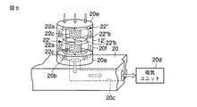
その為の第1の変形例に従ったガス検知器12´が図5中に図示されている。 A gas detector 12 'according to a first modification for this purpose is shown in FIG.
第1の変形例に従ったガス検知器12´は、支持体20の所定の位置に固定されている台座20aの凹所20bに第1の弾性表面波素子22´の樽形状の基材22´bの一側面が着座されており、さらに第1の弾性表面波素子22´の樽形状の基材22´bの他側面に第2の弾性表面波素子22´´の樽形状の基材22´´bの一側面が固定されている。第1の弾性表面波素子22´の樽形状の基材22´bと第2の弾性表面波素子22´´の樽形状の基材22´´bとは相互に同じ寸法である。そして、第1の弾性表面波素子22´と第2の弾性表面波素子22´´の一方の弾性表面波周回路22aの少なくとも一部にはすだれ状電極22cの他に所定のガスのみに感応するガス感応膜が設けられており、他方の弾性表面波周回路22aにはすだれ状電極22cの他に何も設けられていない。
The
台座20a上の第1の弾性表面波素子22´と第2の弾性表面波素子22´´とは前述したフィルタ20eを伴った覆い20fにより覆われている。覆い20fは、台座20a上の第1の弾性表面波素子22´と第2の弾性表面波素子22´´とを外力による損傷から防護している。
The first surface
このように構成されている第1の変形例に従ったガス検知器12´においては、第1の弾性表面波素子22´と第2の弾性表面波素子22´´の夫々のすだれ状電極22cに対し同時に同じ高周波信号がバースト状に負荷され、同じ強度の弾性表面波が励起され伝搬される。
In the
そして、第1の弾性表面波素子22´と第2の弾性表面波素子22´´の夫々において弾性表面波周回路22aを所定の回数周回した後の弾性表面波を夫々のすだれ状電極22cによりピックアップし、多周回した後の所定の時刻の位相や強度、あるいは所定回周回するために必要な遅延時間を比較する。そして第1の弾性表面波素子22´と第2の弾性表面波素子22´´において弾性表面波周回路22aの少なくとも一部に所定のガスのみに感応するガス感応膜が設けられている一方の弾性表面波周回路22aのすだれ状電極22cにより上述した如くピックアップされた弾性表面波の受信強度或いは上述した遅延時間から、第1の弾性表面波素子22´と第2の弾性表面波素子22´´において弾性表面波周回路22aに所定のガスのみに感応するガス感応膜が設けられていない他方の弾性表面波周回路22aのすだれ状電極22cにより上述した如くピックアップされた弾性表面波の受信強度或いは上述した遅延時間を差し引けば、それらの差異が前述した所定のガスの濃度により精密に対応した測定値となる。
Then, in each of the first surface
[ガス検知器の第2の変形例]
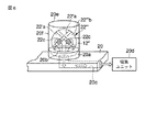
図6中に図示されている如く、第2の変形例に従ったガス検知器12´´は、支持体20の所定の位置に固定されている台座20aの凹所20bに1個の球形状の弾性表面波素子22´´´が着座されている。
[Second Modification of Gas Detector]
As shown in FIG. 6, the
この弾性表面波素子22´´´の基材22´´´bは、弾性表面波を励起可能な材料により形成されていて、その表面に球形状の一部により円環状に連続しており弾性表面波を周回させることが可能な複数の弾性表面波周回路22´aを含んでいる。このような基材は、例えばニオブ酸リチウム、タンタル酸リチウムなどが知られている。そして、複数の弾性表面波周回路22´aの1つにすだれ状電極22cの他に所定のガスのみを吸収又は吸着する物質が設けられており、別の1つの弾性表面波周回路22´aにはすだれ状電極22cの他に何も設けられていない。
The
このような、第2の変形例に従ったガス検知器12´´は、図5を参照しながら前述した第1の変形例に従ったガス検知器12´と同じ機能、即ちガスの濃度測定の結果から温度や圧力の変動による影響を排除する、を果たすことが出来る。そのことに加えて、第2の変形例に従ったガス検知器12´´は1個の球形状の弾性表面波素子22´´´しか使用しないので、2個の樽形状の弾性表面波素子22´及び22´´を必要としている図5を参照しながら前述した第1の変形例に従ったガス検知器12´よりも構成が簡素で製造や組み立てが容易となり、また外形寸法が小型になる。
Such a
なお、第2の変形例に従ったガス検知器12´´のように、複数の弾性表面波周回路22´aを含んでいる基材22´´´bを使用した弾性表面波素子22´´´を使用する場合には、複数の弾性表面波周回路22´aに相互に異なる種類のガスのみに感応するガス感応膜を設けることにより、1つの弾性表面波素子22´´´により相互に異なる種類のガスの濃度を測定することが可能になるし、さらには、そのようなガス感応膜を設けない弾性表面波周回路22´aに相互に異なる種類のガスに感応するガス感応膜を設けた複数の弾性表面波周回路22´aに対するのと同様に同時に同じ強度で同じ周波数のバースト状の高周波信号を適用し、この高周波信号によりこれらの弾性表面波周回路22´aに励起され伝搬される弾性表面を同じ周回数でピックアップし、それらを比較校正することで、前述した如く温度や圧力の変動の影響を排除して相互に異なる種類のガスの濃度を同時に精密に測定することが可能になる。
In addition, like the
図6中に図示されている第2の変形例に従ったガス検知器12´´においても、支持体20の所定の位置に固定されている台座20aの凹所20bに着座されている弾性表面波素子22´´´は、前述したフィルタ20eを伴った覆い20fにより覆われている。
Also in the
前述した第1の実施の形態及びその第1及び第2の変形例に従ったガス濃度分布計測装置10では、複数のガス検知器12,12´,又は12´´が棒状の支持体20上の互いに異なる位置に配置されていて、ガス検知器12,12´,又は12´´を覆うフィルタ12eで囲まれた空間内のガス交換に要する時間を短縮する為に支持体20において複数のガス検知器12,12´,又は12´´に対応した複数の位置が通気孔20cにより吸気ユニット20dに連通されていた。
In the gas concentration
このような構成に代わり、棒状の支持体20上の上述した互いに異なる位置から複数のガス検知器12,12´,又は12´´を除去し、代わりに、支持体20の上記互いに異なる位置からガス濃度分布表示ユニット18の外装ハウジング中に延びてきた複数の通気孔20c中で吸気ユニット20dの手前に複数のガス検知器12,12´,又は12´´を配置することも出来る。この場合には、支持体20の上記互いに異なる位置から通気孔20cを介し吸気ユニット20dにより吸引されたガスがガス濃度分布表示ユニット18の外装ハウジング中で通気孔20c内に配置されているガス検知器12,12´,又は12´´に到達するまでの時間をガス濃度分布の作成時に考慮する必要が在るが、ガス検知器12,12´,又は12´´の弾性表面波素子22,22´,22´´,又は22´´´を上記外装ハウジング中に収容されている前記弾性表面波素子制御部に近接して配置することができるので前記弾性表面波素子制御部によりさらに精密にガス検知器12,12´,又は12´´の弾性表面波素子22,22´,22´´,又は22´´´の動作を制御することが出来るし、弾性表面波素子22,22´,22´´,又は22´´´の温度管理や保守管理がより容易になる。
Instead of such a configuration, the plurality of
[第2の実施の形態]
以下に、図7を参照しながらこの発明の第2の実施の形態に従ったガス濃度分布計測装置30について説明する。
[Second Embodiment]
A gas concentration
ガス濃度分布計測装置30は:相互に異なった複数の位置において夫々の位置で2秒以内に所定のガスの濃度を測定するガス検知器32a,32b,32c,32d,そして32eを含むガス検知部34と;複数種類のガス検知器32a,32b,32c,32d,そして32eの図7の紙面に対して平行な方向(X方向,Y方向)の位置情報に加え図7の紙面に対し直交する方向(Z方向)の位置情報を測定するガス検知器位置情報測定部36と;そして、ガス検知部34の複数種類のガス検知器32a,32b,32c,32d,そして32eが測定したガス濃度の測定値と、複数種類のガス検知器32a,32b,32c,32d,そして32eがガス濃度の測定を終了した時点でガス検知器位置情報測定部36により測定されたガス検知器32a,32b,32c,32d,そして32eの位置情報と、が入力され、これらガス濃度の測定値とこれらガス検知器32a,32b,32c,32d,そして32eの位置情報とを基に、3次元における所定のガス濃度の分布を表示するガス濃度分布表示ユニット38と;を備えている。
The gas concentration
この実施の形態では、支持体40上で図7の縦方向に同一種類のガス検知器32a,32b,32c,32d,又は32eの複数が相互に等間隔で配置されて列を構成しているとともに、図7の横方向に同一種類のガス検知器32a,32b,32c,32d,又は32eにより夫々が構成されている複数の列が相互に等間隔で配列されている。
In this embodiment, a plurality of the same kind of
ガス検知器32a,32b,32c,32d,又は32eの夫々は、例えば図2中に図示されているガス検知器12と同様に図示しない弾性表面波素子により構成されている。 ガス検知部34の板状の支持体40の一部がガス濃度分布表示ユニット38の外装ハウジングの所定の位置に固定されている。ガス検知器位置情報測定部36もまた、ガス濃度分布表示ユニット38の外装ハウジングに固定されている。ガス濃度分布表示ユニット38は、外装ハウジングの外表面に露出した表示装置38a、この実施の形態では液晶表示表示装置、を含んでいる。
Each of the
ガス検知器位置情報測定部36は、図示しない公知の加速度センサ及び角速度センサの少なくともいずれか一方を備えており、この実施の形態では図示しない公知の加速度センサ及び角速度センサの両方を備えている。加速度センサ及び角速度センサの夫々は少なくともX軸とY軸方向の2方向に作用可能であり、さらにZ軸方向を加えた3方向に作用可能である。
The gas detector position
このように構成されているこの発明の第2の実施の形態に従ったガス濃度分布計測装置30は、図1乃至図4を参照しながら前述したこの発明の第1の実施の形態に従ったガス濃度分布計測装置10と同様に使用する。
The gas concentration
このように構成されているこの発明の第2の実施の形態に従ったガス濃度分布計測装置30の機能が、図1乃至図4を参照しながら前述したこの発明の第1の実施の形態に従ったガス濃度分布計測装置10の機能と異なっているのは、2次元的に配置されたガス検知器32a,32b,32c,32d,32eを垂直方向に動かすことで3次元空間におけるガス濃度分布の測定とその表示を行うことである。
The function of the gas concentration
[ガス検知部の複数のガス検知器による所定のガスの濃度の高速度測定方法]
図1乃至図4を参照しながら前述したこの発明の第1の実施の形態に従ったガス濃度分布計測装置10においては、ガス検知部14は支持体20上に支持されている複数のガス検知器12について支持体20の1つの移動位置において複数のガス検知器12のすべてが所定のガスの濃度を測定するのに要する時間は短かければ短いほど良い。
[High-speed measurement method for the concentration of a given gas using multiple gas detectors in the gas detector]
In the gas concentration
なぜならば、所定の空間において所定のガスの濃度の計測を開始する初期位置から所定のガスの濃度の計測を終了する終了位置までの間で支持体20の複数のガス検知器12のすべてが所定のガスの濃度を測定できる移動位置の数を増大させることができるし、また1つの移動位置で支持体20の複数のガス検知器12のすべてに所定のガスの濃度を繰り返し測定させることが出来るからである。そして前者の場合には、所定のガスの濃度分布を測定する為に支持体20が走査する2次元における所定のガスの濃度の分布をより細やかに測定することを可能にする。また後者の場合には、所定のガスの濃度分布を測定する為に支持体20が走査する2次元における所定のガスの濃度の測定値の精度をより高めることが出来る。また、支持体20の動きに合わせて所定のガスの濃度分布をリアルタイムに表示装置18aに表示をすることが好ましい。
This is because all of the plurality of
同じことは、図7を参照しながら前述したこの発明の第2の実施の形態に従ったガス濃度分布計測装置30についても言える。
The same can be said for the gas concentration
通常は、上述した1つの測定位置において支持体20の複数のガス検知器12は、ガス濃度分布表示ユニット18の外装ハウジングに収容されている前述した図示されていない公知の弾性表面波素子制御部により1つ1つ順番に所定のガスの濃度測定を行なわされる。これは、前述した図示されていない公知の弾性表面波素子制御部の構成を簡素にし、前述したこの発明の第1の実施の形態に従ったガス濃度分布計測装置10の製造コストを抑制する為とガス濃度分布計測装置10の外形寸法及び重量を出来る限り抑制し、またガス濃度分布計測装置10の駆動に要する電力を抑制してガス濃度分布計測装置10の為の電源の容量を小さく出来てガス濃度分布計測装置10の携帯性を向上させる為である。
Normally, the plurality of
とはいうものの、上述した1つの測定位置において支持体20の複数のガス検知器12に所定のガスの濃度を1つ1つ順番に測定させるこのような従来の所定のガスの濃度の測定方法では、ガス検知部14の支持体20上に支持されている複数のガス検知器12について支持体20の1つの移動位置において複数のガス検知器12のすべてが所定のガスの濃度を測定するのに要する時間を短縮させるには限度がある。
Nevertheless, such a conventional method for measuring the concentration of a predetermined gas in which the plurality of
次には、ガス検知部14の複数のガス検知器12による所定のガスの濃度をより高速度に測定する為の方法について図8乃至図10を参照しながら説明する。
Next, a method for measuring the concentration of a predetermined gas at a higher speed by the plurality of
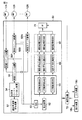
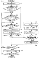
図8中に図示されている如く、ガス検知部14の前述した弾性表面波素子制御部50は、設定周波数発生装置(高周波信号発生手段)52、設定長バースト切り出し装置54、送信スイッチ装置(切替手段)56、受信スイッチ装置58A,58B,〜58N、ADコンバータ(ADC)60、検波装置62、加算装置64、平均化装置66、記憶装置68、そしてインターフェース(IF)70を備えている。弾性表面波素子制御部50は、ガス濃度分布表示ユニット18の外装ハウジングに格納されておりガス濃度分布計測装置10の全体の動作を制御する制御装置72に接続されていて、制御装置72にはガス濃度分布表示ユニット18の表示装置18a及び入力装置18bも接続されている。
As shown in FIG. 8, the surface acoustic
設定周波数発生装置52は、ガス検知部14のガス検知器12の弾性表面波素子22の特性に合わせた目的の周波数を励振する。ここでは、単一の設定周波数発生装置52が高周波信号を発生する。
The
設定長バースト切り出し装置54は、設定周波数発生装置52で励振された高周波信号を任意に定めた時間長毎に切り出すスイッチ装置である。これにより、高周波バースト信号が生成される。設定長バースト切り出し装置54は、高周波信号を切り出す時間を弾性表面波が弾性表面波周回路22aを1周する時間よりも短くなるように調整する。これにより、弾性表面波素子12A〜12Nの夫々から弾性表面波が弾性表面波周回路22aを1周する度に繰り返し出力される信号を時間分離することができる。
The set-length
送信スイッチ装置56は、設定長バースト切り出し装置54により切り出された高周波バースト信号を弾性表面波素子12A〜12Nの夫々に切り替えながら夫々のすだれ状電極22cに送信する。送信スイッチ装置56は、弾性表面波素子12A〜12Nの夫々の弾性表面波周回路22aを弾性表面波が1周する時間以上の時間をかけて高周波バースト信号の入力先を順次切り替える。補足すると、高周波バースト信号の入力先の切り替えタイミングと、弾性表面波素子12A〜12Nの夫々の基材22bの弾性表面波周回路22aの直径とは比例する。そのため、送信スイッチ装置56は、高周波バースト信号が150MHzの場合、弾性表面波素子12A〜12Nの夫々の基材22bが直径1mmの水晶球であれば1μs以上の時間をかけて入力先を切り替え、上記基材22bの直径が3.3mmであれば3.3μs以上の時間が経ってから入力先を切り替える。
The
送信スイッチ装置56は、弾性表面波素子12A〜12Nへの高周波バースト信号の入力先を切り替える時刻と弾性表面波素子12A〜12Nのいずれかのすだれ状電極22cからの出力信号が検出される時刻とが一致する場合、高周波バースト信号の入力を待機する。これにより、入力信号の影響により出力信号が検出されなくなることを回避できるので、高精度に出力信号を検出することができる。
The
受信スイッチ装置58A〜58Nは弾性表面波素子12A〜12Nの夫々に対応して設けられており、弾性表面波素子12A〜12Nの夫々の弾性表面波周回路22aに励起され周回されている弾性表面波の周回信号をすだれ状電極22cから取り出すタイミングを決定する。ここで受信スイッチ装置58A〜58Nは、100周目の出力信号を解析すべき信号として弾性表面波素子12A〜12Nの夫々の弾性表面波周回路22aからすだれ状電極22cを介して取り出す。弾性表面波素子12A〜12Nの夫々から取り出された出力信号は、ADコンバータ60に送出される。なお、上記の100周目というのは例示であり、解析すべき出力信号を弾性表面波素子12A〜12Nの夫々の弾性表面波周回路22aからすだれ状電極22cを介して取り出す時の周回数は弾性表面波素子12A〜12Nの夫々の特性や解析すべき信号から解析される内容に応じて任意に設定される。
The receiving
ADコンバータ(ADC)60は、アナログの上記出力信号をデジタル信号に変換する。なおここでADコンバータ(ADC)60に入力されるアナログ信号は、高周波信号の周波数をヘテロダイン方式によりダウンコンバートされた後のアナログ信号でも良い。 The AD converter (ADC) 60 converts the analog output signal into a digital signal. Here, the analog signal input to the AD converter (ADC) 60 may be an analog signal after the frequency of the high-frequency signal is down-converted by the heterodyne method.
弾性表面波素子12A〜12Nのすだれ状電極22cには、送信スイッチ装置56により時間差を伴い高周波バースト信号が入力される。そのため、送信スイッチ装置56が切り替え動作を行なわない間に、弾性表面波素子12A〜12Nの夫々のすだれ状電極22cから取り出された出力信号がADコンバータ60に入ってくる。この結果、弾性表面波素子12A〜12Nの夫々からの出力信号は相互に分離されているので、ADコンバータ60の使用は1つだけよい。
A high frequency burst signal is input to the
検波装置62は、ADコンバータ60でデジタル化された出力信号を演算により位相と強度のデータに変換する。
The
最初の弾性表面波素子12Aから最後の弾性表面波素子12Nまでへの高周波バースト信号の入力は、制御装置72により設定される「平均化回数」繰り返して実行される。
The input of the high frequency burst signal from the first surface
加算装置64は、弾性表面波素子12A〜12Nの夫々のすだれ状電極22cからの所定の周回数の出力信号からADコンバータ60を経て検波装置62で変換された上記「平均化回数」の位相と強度のデータを加算する。加算装置64は、弾性表面波素子12A〜12Nに対応した記憶領域64A〜64Nを有しており、記憶領域64A〜64Nの夫々は夫々において加算された上記データを一時保存する。加算装置64は、データを演算する機能も有する。
The
平均化装置66は記憶領域64A〜64Nに対応した個別平均化部66A〜66Nを備えている。個別平均化部66A〜66Nの夫々は、最初の弾性表面波素子12Aから最後の弾性表面波素子12Nまでへの高周波バースト信号の入力が、制御装置72により設定される「平均化回数」繰り返して実行された後、弾性表面波素子12A〜12Nの夫々からの上記平均化回数の出力信号を平均化する。具体的には、個別平均化部66A〜66Nの夫々は、加算装置64中の対応する記憶領域64A〜64Nの夫々に保存されている、上記平均化回数の出力信号に対応した上記平均化回数の位相と強度のデータの加算後の位相データと強度データを平均化する。
The averaging
補足すると、弾性表面波素子12A〜12Nの夫々からの1回のみの出力信号を使用して作成した上記データにはノイズの影響が含まれていることがある。従って、上記ノイズの影響を出来る限り少なくするために、弾性表面波素子12A〜12Nの夫々からの上記平均化回数の出力信号を使用して上述した如く平均化された位相データと強度データを得る。
Supplementally, the above-mentioned data created by using only one-time output signals from the surface
即ち、n個目の最後の弾性表面波素子12Nからの所定の周回数の出力信号に対応したデジタル信号の位相と強度のデータが記憶されると、上述した平均化回数に達するまで、再度、最初の弾性表面波素子12Aから最後の弾性表面波素子12Nまでの夫々の所定の周回数の出力信号に対応したデジタル信号の位相と強度のデータの測定が開始される。
That is, when the phase and intensity data of the digital signal corresponding to the output signal of the predetermined number of rounds from the n-th last surface
この間に、2回目以降の各回に行なわれる最初の弾性表面波素子12Aから最後の弾性表面波素子12Nまでの夫々の上記データの測定は、最初の弾性表面波素子12Aから最後の弾性表面波素子12Nまでの夫々において前回に励起され周回された弾性表面波の影響がなくなってから行なわれる必要がある。具体的には、直径1mmの水晶球を基材22bとして使用している弾性表面波素子12A〜12Nの夫々に入力される高周波バースト信号の周波数が150MHzの場合、前回に弾性表面波素子12A〜12Nの夫々に高周波バースト信号を入力してから次回に弾性表面波素子12A〜12Nの夫々に高周波バースト信号を入力するまでには1ms以上の時間を経過させれば十分である。
In the meantime, the measurement of the above-mentioned data from the first surface
なお、上述した如く複数の弾性表面波素子12A〜12Nの夫々に対応した複数の個別平均化部66A〜66Nを使用して複数の弾性表面波素子12A〜12Nの夫々の上記データの平均化された値を得る代わりに、複数の個別平均化部66A〜66Nを備えずに複数の弾性表面波素子12A〜12Nに対応して1つの共通の平均化部のみを使用する平均化装置を使用し、上記1つの共通の平均化部を複数の弾性表面波素子12A〜12Nの夫々に、具体的には加算装置64において複数の弾性表面波素子12A〜12Nの夫々に対応している記憶領域64A〜64Nの夫々に、順番に対応させて、複数の弾性表面波素子12A〜12Nの夫々に対応している記憶領域64A〜64Nの夫々に加算されている上記データの平均化された値を得ることも出来る。
As described above, the data of each of the plurality of surface
記憶装置68は、平均化装置66の複数の個別平均化部66A〜66Nに対応した複数の個別記憶部68A〜68Nを備えている。複数の個別記憶部68A〜68Nは対応している複数の個別平均化部66A〜66Nにおいて平均化された上記データの値を記憶する。
The
複数の個別記憶部68A〜68Nは対応している複数の個別平均化部66A〜66Nにおいて平均化された上記データの値の他に、複数の弾性表面波素子12A〜12Nの夫々に対応している付帯データを保存する領域も有している。
The plurality of individual storage units 68A to 68N correspond to the plurality of surface
ここでは、複数の弾性表面波素子12A〜12Nの複数の個別平均化部66A〜66Nに対応して複数の個別記憶部68A〜68Nが設けられているが、記憶装置68が1つの記憶部しか備えておらず、その1つの記憶部の中に複数の個別平均化部66A〜66Nにおいて平均化された上記データの値、或いは複数の弾性表面波素子12A〜12Nに対応して1つの共通の平均化部のみを使用する平均化装置を使用して前述した如く平均化された上記データの値、を相互に異なるアドレスをつけて切り分けて保存することも出来る。
Here, a plurality of individual storage units 68A to 68N are provided corresponding to the plurality of individual averaging units 66A to 66N of the plurality of surface
記憶装置68は、図示されていない外部の処理装置、例えばパーソナルコンピュータ(PC)等、に送信できるような構成としてもよい。
The
インターフェース(IF)70は、前述した各種の装置52〜68の夫々と、ガス濃度分布計測装置10の全体の動作を制御する制御装置72との間の各種のデータの中継を可能としている。具体的には、インターフェース70は、USBやEthernet(登録商標)、Bluetooth(登録商標)、IEEE-1394、PHS、WCDMA、CDMA2000、IEEE-802.xx等の有線及び無線に関係なく命令やデータが転送できるようなものである。また、インターフェース70は、このガス濃度分布計測装置10が他のガス濃度分布計測装置10と連動して動作することを可能とする。
The interface (IF) 70 enables various data to be relayed between the
制御装置72は、設定周波数発生装置52で励振される高周波信号の周波数制御や、設定長バースト切り出し装置54が上記高周波信号を切り出す時間長の調整や、送信スイッチ装置56が行なう弾性表面波素子12A〜12Nの夫々に対する切り替えの制御や、受信スイッチ58A〜58Nが行なう弾性表面波素子12A〜12Nの夫々に対する切り替えの制御等を行ない、検知部14の複数のガス検知器12A〜12Nを使用した所定のガスの濃度の測定を開始する。
The control device 72 controls the frequency of the high frequency signal excited by the set
具体的には、制御装置72は、設定周波数発生装置52が発振した高周波信号から設定長バースト切り出し装置54が切り出した所定の長さのバースト状の高周波信号を最初の弾性表面波素子12Aに入力した後に、最初の弾性表面波素子12Aからの所定の周回数の弾性表面波の出力信号を検出する前に、上記所定の長さのバースト状の高周波信号の入力先を2番目以降の弾性表面波素子12B〜12Nに順次切り替えるように送信スイッチ装置56を制御する。
Specifically, the control device 72 inputs, to the first surface
制御装置72は、最初の弾性表面波素子12Aから最後の弾性表面波素子12Nまで高周波バースト信号を入力させる回数である「平均化回数」を設定し、平均化装置66の個別平均化部66A〜66Nの演算を制御する。制御装置72はさらに、平均化装置66の個別平均化部66A〜66Nにより平均化された後の複数の弾性表面波素子12A〜12Nの夫々からの出力信号に対応したデジタル信号の位相と強度のデータに基づいて、複数の弾性表面波素子12A〜12Nの夫々の弾性表面波周回路22aに励起され所定の周回数周回した後の弾性表面波の特性(即ち、所定のガスの濃度)を測定する。
The control device 72 sets “number of times of averaging”, which is the number of times the high frequency burst signal is input from the first surface
制御装置72は、上述した測定の結果を表示装置18aに表示させたり、入力装置18bを介したデータ入力の受付及び入力数値のエラー処理等を行なう。
The control device 72 displays the above-described measurement results on the
制御装置72には、上述した測定の結果をインターフェース70を介して図示しない外部の記憶装置に保存して管理したり、上述した測定の結果を基礎に報告書を自動的に作成したり、上述した測定の結果をインターネットを介して公開したりする機能を有することもできる。
The control device 72 stores and manages the above measurement results in an external storage device (not shown) via the
制御装置72はさらに、インターフェース70を介して接続された他のガス濃度分布計測装置10の動作の制御を行なうよう構成されていることが出来る。
The control device 72 can be further configured to control the operation of another gas concentration
入力装置18bは、キーボードやマウスや専用の入力装置や表示装置18aの画面に接されたタッチ式入力装置であることが出来る。
The
次に上述した如く構成されている弾性表面波素子制御部50により制御されたガス検知部14の動作を、図9のフローチャート及び図10の信号相関図を用いて説明する。
Next, the operation of the
まず、設定周波数発生装置52により、複数の弾性表面波素子12A〜12Nの特性に合わせた目的の周波数の高周波信号が作り出される(ステップS1)。ここで、最初の弾性表面波素子12Aへの高周波信号の入力が1回目である場合、設定長バースト切り出し装置54を介して、上記高周波信号から所望の長さのバースト状の高周波信号が生成される(ステップS2−YES,ステップS3)。設定長バースト切り出し装置54は、複数の弾性表面波素子12A〜12Nの弾性表面波周回路22aを所定の周回数だけ周回後に取り出される出力信号が相互に時間差を伴い分離されるように、弾性表面波周回路22aに上記バースト状の高周波信号から励起され周回された弾性表面波が弾性表面波周回路22aを1周する周回時間よりも長さが短いバースト状の高周波信号(高周波バースト信号)を生成させる。
First, the
次に、高周波バースト信号が、送信スイッチ装置56により選択された受信スイッチ装置58Aを介して、最初の弾性表面波素子12Aのすだれ状電極22cに入力される。
Next, the high frequency burst signal is input to the
最初の弾性表面波素子12Aのすだれ状電極22cに高周波バースト信号が入力されると、送信スイッチ装置56は、上記高周波バースト信号により最初の弾性表面波素子12Aの弾性表面波周回路22aに励起され周回された弾性表面波が所定の周回後にすだれ状電極22cから取り出されるまでに、高周波バースト信号の入力先が他の弾性表面波素子12B〜12Nのすだれ状電極22cに順次切り替えられる(ステップS4)。
When a high frequency burst signal is input to the
複数の弾性表面波素子12A〜12Nのすだれ状電極22cに高周波バースト信号が入力されると、複数の弾性表面波素子12A〜12Nの弾性表面波周回路22aに弾性表面波が励起され、弾性表面波周回路22aを周回し続ける。
When a high-frequency burst signal is input to the
最初の弾性表面波素子12Aの弾性表面波周回路22aに最初に励起され周回された弾性表面波が所定の回数周回した後にすだれ状電極22c及び受信スイッチ58Aを介して取り出された後には、2番目の弾性表面波素子12Bから最後の弾性表面波素子12Nまで夫々の弾性表面波周回路22aに最初に励起され周回された弾性表面波が所定の回数周回した後にすだれ状電極22c及び対応する受信スイッチ58B〜58Nを介して順次検波され取り出される(ステップS5−Yes)。
After the surface acoustic wave first excited and circulated by the surface
ここでは、弾性表面波が弾性表面波周回路22aを100周したときにすだれ状電極22cにより受信された出力信号が測定対象とされているので、最初の弾性表面波素子12Aのすだれ状電極22cに最初に高周波バースト信号を入力してから100μs以後に、最初の弾性表面波素子12Aのすだれ状電極22cから最後の弾性表面波素子12Nのすだれ状電極22cまで上記出力信号が順次検波され取り出されることになる。
Here, since the output signal received by the
上記出力信号を受信した回数がカウントされた(ステップS6)後、上記出力信号はADコンバータ60によりデジタル化され、デジタル化された出力信号から位相データと強度データとが検波装置62により求められる(ステップS7)。そして、上述した如くカウントされた回数に応じて加算装置64の複数の記憶領域64A〜64Nのいずれかに上記データが振り分けられる(ステップS8)。
After the number of times the output signal has been received is counted (step S6), the output signal is digitized by the
上述した如くカウントされた回数が複数の弾性表面波素子12A〜12Nの個数と同じになった時には、カウントされた回数がリセットされる(ステップS9−YES,S10)。これにより、上述した如くカウントされた回数と複数の弾性表面波素子12A〜12Nのすだれ状電極22cからの上記出力信号とを対応付けることが可能となる。
As described above, when the counted number becomes the same as the number of the plurality of surface
この後、複数の弾性表面波素子12A〜12Nの夫々に対する予め設定された平均化回数分の所定の高周波バースト信号の入力が順次行われる(ステップS11−NO)。
Thereafter, predetermined high frequency burst signals are sequentially input to each of the plurality of surface
なお、複数の弾性表面波素子12A〜12Nの夫々の弾性表面波周回路22aにおいて周回する弾性表面波が発する出力信号が実質的になくなるまでには高周波バースト信号の入力の時点から1ms程度の時間を要する。従って、複数の弾性表面波素子12A〜12Nの夫々の弾性表面波周回路22aに対する2回目以降の高周波バースト信号の入力は、前回の高周波バースト信号の入力から1ms以上経過してから行われる(ステップS12)。すなわち、前回に最初の弾性表面波素子12Aに対し高周波バースト信号を入力した後、次に最初の弾性表面波素子12Aに対し高周波バースト信号を入力する場合、制御装置72が、前回に最初の弾性表面波素子12Aに対し高周波バースト信号を入力した時から1ms以上経過しているかどうかを判断し、1ms以上経っていなければ(ステップS12−NO)、1ms以上経過するまで待つ。また、制御装置72は、複数の弾性表面波素子12A〜12Nの夫々の弾性表面波周回路22aに対し高周波バースト信号を入力するタイミングがステップS5の検波タイミングと重ならないないかどうかを判断し、重なっていたら、重ならないように、高周波バースト信号を入力するタイミングをずらす(ステップS13)。その後、ステップ3に進む。
It should be noted that a time of about 1 ms from the time of input of the high-frequency burst signal until the output signal generated by the surface acoustic wave that circulates in each of the surface
上述のステップS3〜S13までの処理が平均化回数まで実行されると(ステップS11−YES)、複数の弾性表面波素子12A〜12Nの夫々からの前述したデータが加算装置64の対応する記憶領域64A〜64Nに平均化回数まで加算されていた後のデータが平均化装置66の対応する個別平均化部66A〜66Nにおいて平均化回数により平均値を算出される(ステップS14)。このように算出された前述したデータの平均値は、記憶装置68において複数の弾性表面波素子12A〜12Nの夫々に対応している個別記憶部68A〜68Nに記憶される。
When the processing from the above-described steps S3 to S13 is executed up to the number of times of averaging (step S11-YES), the above-described data from each of the plurality of surface
この後、上述のステップS3〜S14までの処理は、ガス濃度分布計測装置10が所望の空間領域の所定のガスの濃度の測定を終了するまで実行される(ステップS15)。
Thereafter, the processing from step S3 to step S14 described above is executed until the gas concentration
[ガス濃度分布計測装置の作用効果]
以上説明したように、本実施形態に係るガス濃度分布計測装置10は、高周波バースト信号を最初の弾性表面波素子12Aに入力した場合、最初の弾性表面波素子12Aにおいて所定の数まで周回した弾性表面波からの出力信号を最初に検出するまでの間に、高周波バースト信号の入力先を他の弾性表面波素子12B〜12Nに順次切り替える。そして、最初の弾性表面波素子12Aにおいて所定の数まで周回した弾性表面波からの出力信号を最初に検出した後には、2番目の弾性表面波素子12Bから最後の弾性表面波素子12Nまでの夫々において所定の数まで周回した弾性表面波からの出力信号を順次検出する。
[Effects of gas concentration distribution measuring device]
As described above, in the gas concentration
この結果として、本実施形態に係るガス濃度分布計測装置10では、単一の設定周波数発生装置52から設定長バースト切り出し装置54を介して所定の高周波バースト信号が入力される複数の弾性表面波素子12A〜12Nの全てから所定の数まで周回した弾性表面波の出力信号を検出する場合、1つの弾性表面波素子に所定の高周波バースト信号を入力し、そして上記1つの弾性表面波素子から所定の数まで周回した弾性表面波の出力信号を検出し、その後に次の1つの弾性表面波素子に所定の高周波バースト信号を入力し、そして上記次の1つの弾性表面波素子から所定の数まで周回した弾性表面波の出力信号を検出することを弾性表面波の数だけ繰り返し行なうよりも、複数の弾性表面波素子12A〜12Nの全てから所定の数まで周回した弾性表面波の出力信号を検出するまでに要する時間を少なくすることが出来る。
As a result, in the gas concentration
以下、具体例を挙げて説明する。 Hereinafter, a specific example will be described.
この具体例では、使用される複数の弾性表面波素子12A〜12Nの夫々の球形状の基材の直径は1mmであり、送信スイッチ装置56における複数の弾性表面波素子12A〜12Nに対応した複数の受信スイッチ装置58A〜58Nに対する切り替えタイミングは1μsである。そして、複数の弾性表面波素子12A〜12Nの夫々から所定の数まで周回した弾性表面波の出力信号を256回検出し、夫々の出力信号からADコンバータ60そして検波装置62を介して得られたデジタル化された出力信号の位相と強度のデータの256回分を加算装置64の中の複数の記憶領域64A〜64Nの対応するいずれか1つに加算し、さらに平均化装置66中の複数の個別平均化部66A〜66Nの対応する1つにおいて平均化する。なお次回に1つの弾性表面波素子から所定の数まで周回した弾性表面波の出力信号を検出する際には、この1つの弾性表面波素子において所定の数まで周回した弾性表面波の出力信号を前回検出した時の弾性表面波の影響を避ける為に、この1つの弾性表面波素子において所定の高周波バースト信号を前回入力してから1ms待機してから次回にこの1つの弾性表面波素子に対し所定の高周波バースト信号を入力する。
In this specific example, the diameter of each spherical base material of the plurality of surface
そして、1つの弾性表面波素子から上述した如くデータを得る為に弾性表面波の出力信号を得る時の弾性表面波の所定の周回数は100としている。 In order to obtain data from one surface acoustic wave element as described above, the predetermined number of rounds of the surface acoustic wave when obtaining the output signal of the surface acoustic wave is 100.
弾性表面波素子の直径1mmの球形状の基体22bの弾性表面波周回経路22aを弾性表面波が1周するのに要する時間は1μsである。そして、送信スイッチ装置56が所定の長さの高周波バースト信号を入力する弾性表面波素子を1μs毎に切り替えると、1つの弾性表面波素子において前回励起され周回された弾性表面波の影響が無くなる時間である1msの間に、1000個の弾性表面波素子に所定の長さの高周波バースト信号を入力することが可能となる。
The time required for the surface acoustic wave to make one round of the surface acoustic
それ故に、1個の弾性表面波素子から所定の数まで周回した弾性表面波の出力信号を検出することを256回繰り返し、この256個の出力信号の夫々から前述した如く得た位相及び強度のデータの平均値を求める場合、1個の弾性表面波素子に対し繰り返し所定の長さの高周波バースト信号を入力するのは少なくとも前述した如く1ms毎でなければならないので、1ms×256(回)=256msの時間が必要となる。 Therefore, detecting the output signal of the surface acoustic wave that has circulated from one surface acoustic wave element to a predetermined number is repeated 256 times, and the phase and intensity obtained as described above from each of the 256 output signals are repeated. When obtaining an average value of data, it is necessary to repeatedly input a high-frequency burst signal of a predetermined length to one surface acoustic wave element at least every 1 ms as described above, so 1 ms × 256 (times) = A time of 256 ms is required.
しかし、この1msの間に前述した如く1μs毎に1つの弾性表面波素子に対し所定の長さの高周波バースト信号を入力することにより他の1000個の弾性表面波素子に対し所定の長さの高周波バースト信号を入力することが出来る。 However, as described above, by inputting a high-frequency burst signal having a predetermined length to one surface acoustic wave element every 1 μs during this 1 ms, a predetermined length is applied to the other 1000 surface acoustic wave elements. High frequency burst signal can be input.
これに対し前述した従来の如く1つの弾性表面波素子から所定の数まで周回した弾性表面波の出力信号を検出することを256回繰り返し、この256個の出力信号の夫々から前述した如く得た位相及び強度のデータの平均値を求めた後に、次の弾性表面波素子に対し所定の高周波バースト信号を入力する場合には、256ms毎にしか1つの弾性表面波素子に対し所定の長さの高周波バースト信号を入力することが出来ない。 On the other hand, the detection of the surface acoustic wave output signal from a single surface acoustic wave element to a predetermined number as described above was repeated 256 times, and each of these 256 output signals was obtained as described above. When a predetermined high-frequency burst signal is input to the next surface acoustic wave element after obtaining the average value of the phase and intensity data, the predetermined length of one surface acoustic wave element has a predetermined length only every 256 ms. High frequency burst signal cannot be input.
即ち、前者の場合と後者の従来の場合とを比べると、同じ個数の弾性表面波素子を使用し全ての弾性表面波素子から前述した平均値を求めるまでに要する時間は、前者の場合の方が後者の従来の場合よりも遥かに短い時間しか必要としないことがわかる。 That is, when comparing the former case with the latter conventional case, the time required to obtain the above-mentioned average value from all the surface acoustic wave elements using the same number of surface acoustic wave elements is the same as that of the former case. It can be seen that this requires much shorter time than the latter conventional case.
10…ガス濃度分布計測装置、12,12´,12´´…ガス検知器、14…ガス検知部、16…ガス検知器位置情報測定部、18…ガス濃度分布表示ユニット、18a…表示装置、18b…入力装置、20…支持体、20a…台座、20b…凹所、20c…通気孔(ガス交換要素)、20d…吸気ユニット(ガス交換要素)、20e…フィルタ、20f…覆い、22…弾性表面波素子、22´…第1の弾性表面波素子、22´´…第2の弾性表面波素子、22´´´…弾性表面波素子、22a…弾性表面波周回路、22´a…弾性表面波周回路、22b…基材、22´b…基材、22´´b…基材、22´´´b…基材、22c…すだれ状電極、30…ガス濃度分布計測装置、32a,32b,32c,32d,32e…ガス検知器、34…ガス検知部、36…ガス検知器位置情報測定部、38…ガス濃度分布表示ユニット、38a…表示装置、40…支持体、50…弾性表面波素子制御部、52…設定周波数発生装置(高周波信号発生手段)、54…設定長バースト切り出し装置、56…送信スイッチ装置(切替手段)、58A,58B,〜58N…受信スイッチ装置、60…ADコンバータ(ADC)、62…検波装置、64…加算装置、64A,64B,〜64N…記憶部、66…平均化装置、66A,66B,〜66N…個別平均化部、68…記憶装置、68A,68B,〜68N…個別記憶部、70…インターフェース(IF)、72…制御装置。
DESCRIPTION OF
Claims (6)
前記ガス検知部の複数のガス検知器の位置情報を測定するガス検知器位置情報測定部と;
前記ガス検知部の複数のガス検知器が測定したガス濃度の測定値と、複数のガス検知器がガス濃度の測定を終了した時点でガス検知器位置情報測定部により測定された複数のガス検知器の位置情報と、が入力され、前記ガス濃度の測定値と前記ガス検知器の位置情報とを基に、前記ガス検知部が移動した空間における前記所定のガスの濃度の分布を表示するガス濃度分布表示ユニットと;
を備えており、
前記ガス検知器が、球形状の一部により円環状に連続しており弾性表面波を周回させる弾性表面波周回路を少なくとも1つ含む弾性表面波素子を含む、
ことを特徴とするガス濃度分布計測装置。 Each is supported the plurality of gas detectors for measuring the concentration of a predetermined gas in a plurality of positions of a predetermined distance, together with the vent extending from the plurality of positions are formed, the vent hole In order to suck the predetermined gas from the plurality of positions, a linear support body having an intake unit connected to an extended end of the vent hole is provided, and a relative relationship between the plurality of gas detectors is provided. A gas detector that moves while maintaining its position;
A gas detector position information measuring unit for measuring position information of a plurality of gas detectors of the gas detector;
Gas concentration measurement values measured by a plurality of gas detectors of the gas detector and a plurality of gas detectors measured by the gas detector position information measuring unit when the gas detectors finish measuring the gas concentration Gas for displaying the distribution of the concentration of the predetermined gas in the space in which the gas detection unit has moved based on the measured value of the gas concentration and the position information of the gas detector. A concentration distribution display unit;
Equipped with a,
The gas detector includes a surface acoustic wave element including at least one surface acoustic wave circuit that circulates a surface acoustic wave that is continuous in an annular shape with a part of a spherical shape.
A gas concentration distribution measuring device characterized by that.
ことを特徴とする請求項1に従っているガス濃度分布計測装置。 The gas detector position information measuring unit includes at least one of an acceleration sensor and an angular velocity sensor.
A gas concentration distribution measuring device according to claim 1.
前記通気孔と前記吸気ユニットが上記フィルタに覆われた空間に含まれるガスを上記フィルタを取り囲む外部空間のガスと入れ替えるガス交換要素を構成している、
ことを特徴とする請求項1又は2に従っているガス濃度分布計測装置。 The gas detector includes a filter that covers the surface acoustic wave element and prevents contact of foreign matter except gas with respect to the surface acoustic wave circuit of the surface acoustic wave element,
The vent hole and the intake unit constitute a gas exchange element that replaces the gas contained in the space covered by the filter with the gas in the external space surrounding the filter,
A gas concentration distribution measuring apparatus according to claim 1 or 2, characterized in that
一方の弾性表面波素子の弾性表面波周回路の少なくとも一部は前記ガスに対し感応するガス感応膜により覆われ、他方の弾性表面波素子の弾性表面波周回路は全体が前記ガスに対し露出されている、
ことを特徴とする請求項3に従っているガス濃度分布計測装置。 The gas detector includes two surface acoustic wave elements, and
At least part of the surface acoustic wave circuit of one surface acoustic wave element is covered with a gas sensitive film sensitive to the gas, and the entire surface acoustic wave circuit of the other surface acoustic wave element is exposed to the gas. Being
A gas concentration distribution measuring device according to claim 3.
一方の弾性表面波素子の弾性表面波周回路の少なくとも一部は前記ガスに対し感応するガス感応膜により覆われ、他方の弾性表面波周回路の少なくとも一部は前記ガスに対し前記一方の弾性表面波素子のガス感応膜とは異なる感応を示すガス感応膜により覆われている、
ことを特徴とする請求項3又は4に従っているガス濃度分布計測装置。 The gas detector includes two surface acoustic wave elements, and
At least a part of the surface acoustic wave circuit of one surface acoustic wave element is covered with a gas-sensitive film sensitive to the gas, and at least a part of the other surface acoustic wave circuit is elastic to the gas with respect to the gas. Covered with a gas sensitive film that shows a different sensitivity from the gas sensitive film of the surface wave device,
A gas concentration distribution measuring device according to claim 3 or 4, characterized in that.
前記ガス濃度分布表示ユニットは、ガス検知部が移動した2次元空間における所定のガス濃度の分布を表示するガス濃度分布表示ユニットである、
ことを特徴とする請求項1乃至5のいずれか1項に従っているガス濃度分布計測装置。 The gas detection unit is a gas detection unit in which a plurality of gas detectors are arranged in a line,
The gas concentration distribution display unit is a gas concentration distribution display unit that displays a predetermined gas concentration distribution in a two-dimensional space in which the gas detection unit has moved.
A gas concentration distribution measuring device according to any one of claims 1 to 5 .
Priority Applications (2)
| Application Number | Priority Date | Filing Date | Title |
|---|---|---|---|
| JP2008058278A JP5141304B2 (en) | 2008-03-07 | 2008-03-07 | Gas concentration distribution measuring device |
| US12/379,998 US8166799B2 (en) | 2008-03-07 | 2009-03-05 | Gas concentration distribution measuring apparatus |
Applications Claiming Priority (1)
| Application Number | Priority Date | Filing Date | Title |
|---|---|---|---|
| JP2008058278A JP5141304B2 (en) | 2008-03-07 | 2008-03-07 | Gas concentration distribution measuring device |
Publications (2)
| Publication Number | Publication Date |
|---|---|
| JP2009216458A JP2009216458A (en) | 2009-09-24 |
| JP5141304B2 true JP5141304B2 (en) | 2013-02-13 |
Family
ID=41061490
Family Applications (1)
| Application Number | Title | Priority Date | Filing Date |
|---|---|---|---|
| JP2008058278A Expired - Fee Related JP5141304B2 (en) | 2008-03-07 | 2008-03-07 | Gas concentration distribution measuring device |
Country Status (2)
| Country | Link |
|---|---|
| US (1) | US8166799B2 (en) |
| JP (1) | JP5141304B2 (en) |
Families Citing this family (8)
| Publication number | Priority date | Publication date | Assignee | Title |
|---|---|---|---|---|
| JP5422938B2 (en) * | 2008-08-19 | 2014-02-19 | 凸版印刷株式会社 | Fluid measuring device |
| DE102012006047B3 (en) * | 2012-03-27 | 2013-08-01 | Deutsches Zentrum Für Luft- Und Raumfahrt | Device for determining gas concentrations in investigation volume e.g. clean room used in semiconductor manufacture, has beam steering unit that steers beam from radiation source on spectrometer over beam paths between deflection units |
| CN103674759B (en) * | 2013-12-13 | 2016-08-10 | 青岛云路先进材料技术有限公司 | A kind of measuring method detecting porosity of refractory material |
| CN105761439B (en) * | 2014-12-17 | 2019-09-13 | 富泰华工业(深圳)有限公司 | Mobile terminal, system and method for detecting air pollution |
| CN104775849B (en) * | 2015-03-23 | 2016-09-21 | 山东科技大学 | Gas and coal spontaneous combustion coupling disaster monitoring system and monitoring method in coal mine stope |
| CN109813633B (en) * | 2019-01-29 | 2021-08-13 | 郑州大学 | A device for measuring viscosity-temperature coefficient of air-containing lubricating oil and its real-time measurement method |
| CN115420562B (en) * | 2022-10-08 | 2026-04-03 | 浙江新寰科环保科技股份有限公司 | A method for online carbon monitoring and the equipment used therein |
| CN117214407B (en) * | 2023-09-12 | 2026-02-10 | 三盈联合科技股份有限公司 | A combustible gas detection device for fuel dispensers |
Family Cites Families (13)
| Publication number | Priority date | Publication date | Assignee | Title |
|---|---|---|---|---|
| JPH0434439Y2 (en) * | 1989-08-31 | 1992-08-17 | ||
| WO2001045255A1 (en) * | 1999-12-17 | 2001-06-21 | Toppan Printing Co., Ltd. | Saw device |
| JP2002372544A (en) * | 2001-06-15 | 2002-12-26 | Kurita Water Ind Ltd | Gas concentration distribution measurement device and gas generation prevention device |
| DE10133567A1 (en) * | 2001-07-13 | 2003-01-30 | Inficon Gmbh | Sniffing leak detector and method for its operation |
| WO2003032487A1 (en) * | 2001-10-09 | 2003-04-17 | Toppan Printing Co., Ltd. | Surface acoustic wave element, electric signal processing device using the surface acoustic wave element, environment evaluation device using the electric signal processing device, and analyzing method using the surface acoustic wave element |
| US7112447B2 (en) * | 2002-09-27 | 2006-09-26 | Spx Corporation | Hand held gas analyzer |
| WO2004086028A1 (en) * | 2003-03-26 | 2004-10-07 | Toppan Printing Co., Ltd | Sensor head, gas sensor and sensor unit |
| JP2005030909A (en) * | 2003-07-11 | 2005-02-03 | Shimadzu Corp | Odor distribution measuring method and apparatus, and odor source identifying apparatus |
| EP2482452B1 (en) * | 2003-09-19 | 2013-11-13 | Toppan Printing Co., Ltd. | Surface acoustic wave device and environmental difference detecting apparatus using the surface acoustic wave device |
| JP2005189070A (en) * | 2003-12-25 | 2005-07-14 | Seiko Epson Corp | Piezoelectric vibrator microbalance measurement system |
| JP2006349446A (en) * | 2005-06-15 | 2006-12-28 | Auto Network Gijutsu Kenkyusho:Kk | Moving distance calculation device |
| JP2007271577A (en) | 2006-03-31 | 2007-10-18 | Ball Semiconductor Kk | Sensor head and gas sensor |
| JP4780771B2 (en) * | 2006-05-17 | 2011-09-28 | 凸版印刷株式会社 | Odor sensing system |
-
2008
- 2008-03-07 JP JP2008058278A patent/JP5141304B2/en not_active Expired - Fee Related
-
2009
- 2009-03-05 US US12/379,998 patent/US8166799B2/en not_active Expired - Fee Related
Also Published As
| Publication number | Publication date |
|---|---|
| US8166799B2 (en) | 2012-05-01 |
| US20090229344A1 (en) | 2009-09-17 |
| JP2009216458A (en) | 2009-09-24 |
Similar Documents
| Publication | Publication Date | Title |
|---|---|---|
| JP5141304B2 (en) | Gas concentration distribution measuring device | |
| JP2010048580A (en) | Device and method for measuring fluid, and apparatus for measuring space fluid distribution | |
| JP7658984B2 (en) | Odor measuring device, control device, and odor determining method | |
| KR20140121361A (en) | Improved analyte meter and method of operation | |
| JP5062258B2 (en) | Elastic wave measuring apparatus and method | |
| JP2022146407A (en) | Environmental noise detection device, measuring system and environmental noise detection method | |
| JPWO2019009376A1 (en) | Sterilization treatment device and sterilization treatment method | |
| JP2014130046A (en) | Method for measuring optical rotation, method for measuring component concentration, device for measuring optical rotation and medical equipment | |
| JP6817808B2 (en) | Biological monitoring device and urine analysis method | |
| JP4226003B2 (en) | Sensing device | |
| JP2020165826A (en) | Gas sensor and gas detection system | |
| CN112345206A (en) | Galvanometer testing device, method, equipment and computer readable storage medium | |
| US20240426726A1 (en) | Substance detection system | |
| JP2009109343A (en) | Spherical surface acoustic wave device and odor sensing system for odor sensor | |
| CN112639438B (en) | Laser sensor module indicating readiness for use | |
| TWI338138B (en) | ||
| JP2007240297A (en) | Spherical surface acoustic wave element and spherical optical element | |
| JP5470994B2 (en) | Surface acoustic wave measuring device | |
| JP2003329430A (en) | Inspection object thickness measurement method | |
| JP4441019B2 (en) | Sensor cleaning method, sensor cleaning device, measuring method and measuring device | |
| JP6904496B1 (en) | Smell detector, odor detection method and program | |
| JP4876562B2 (en) | Spherical surface acoustic wave device | |
| CN116698599B (en) | Mechanical property measuring system and method | |
| JP4399314B2 (en) | Method and apparatus for driving measurement of surface acoustic wave device | |
| JPH01112103A (en) | Shape distortion inspecting device for discoid body |
Legal Events
| Date | Code | Title | Description |
|---|---|---|---|
| A621 | Written request for application examination |
Free format text: JAPANESE INTERMEDIATE CODE: A621 Effective date: 20110224 |
|
| A521 | Written amendment |
Free format text: JAPANESE INTERMEDIATE CODE: A523 Effective date: 20120223 |
|
| A977 | Report on retrieval |
Free format text: JAPANESE INTERMEDIATE CODE: A971007 Effective date: 20120725 |
|
| A131 | Notification of reasons for refusal |
Free format text: JAPANESE INTERMEDIATE CODE: A131 Effective date: 20120807 |
|
| A521 | Written amendment |
Free format text: JAPANESE INTERMEDIATE CODE: A523 Effective date: 20120928 |
|
| TRDD | Decision of grant or rejection written | ||
| A01 | Written decision to grant a patent or to grant a registration (utility model) |
Free format text: JAPANESE INTERMEDIATE CODE: A01 Effective date: 20121023 |
|
| A01 | Written decision to grant a patent or to grant a registration (utility model) |
Free format text: JAPANESE INTERMEDIATE CODE: A01 |
|
| A61 | First payment of annual fees (during grant procedure) |
Free format text: JAPANESE INTERMEDIATE CODE: A61 Effective date: 20121105 |
|
| FPAY | Renewal fee payment (event date is renewal date of database) |
Free format text: PAYMENT UNTIL: 20151130 Year of fee payment: 3 |
|
| R150 | Certificate of patent or registration of utility model |
Free format text: JAPANESE INTERMEDIATE CODE: R150 |
|
| LAPS | Cancellation because of no payment of annual fees |