JP5069554B2 - Imaging lens - Google Patents
Imaging lens Download PDFInfo
- Publication number
- JP5069554B2 JP5069554B2 JP2007339266A JP2007339266A JP5069554B2 JP 5069554 B2 JP5069554 B2 JP 5069554B2 JP 2007339266 A JP2007339266 A JP 2007339266A JP 2007339266 A JP2007339266 A JP 2007339266A JP 5069554 B2 JP5069554 B2 JP 5069554B2
- Authority
- JP
- Japan
- Prior art keywords
- lens
- optical axis
- imaging
- object side
- imaging lens
- Prior art date
- Legal status (The legal status is an assumption and is not a legal conclusion. Google has not performed a legal analysis and makes no representation as to the accuracy of the status listed.)
- Active
Links
- 238000003384 imaging method Methods 0.000 title claims description 60
- 230000014509 gene expression Effects 0.000 claims description 38
- 230000003287 optical effect Effects 0.000 claims description 29
- 239000000463 material Substances 0.000 claims description 9
- 239000011347 resin Substances 0.000 claims description 5
- 229920005989 resin Polymers 0.000 claims description 5
- 230000004075 alteration Effects 0.000 description 31
- 238000010586 diagram Methods 0.000 description 13
- 239000011521 glass Substances 0.000 description 6
- 201000009310 astigmatism Diseases 0.000 description 5
- 230000005499 meniscus Effects 0.000 description 3
- 206010010071 Coma Diseases 0.000 description 2
- 230000000295 complement effect Effects 0.000 description 1
- 230000007423 decrease Effects 0.000 description 1
- 239000006185 dispersion Substances 0.000 description 1
- 238000001746 injection moulding Methods 0.000 description 1
- 238000004519 manufacturing process Methods 0.000 description 1
- 229910044991 metal oxide Inorganic materials 0.000 description 1
- 150000004706 metal oxides Chemical class 0.000 description 1
- 230000002093 peripheral effect Effects 0.000 description 1
- 239000004065 semiconductor Substances 0.000 description 1
- 238000004904 shortening Methods 0.000 description 1
Images


Landscapes
- Lenses (AREA)
Description
本発明は、携帯端末、PDA(Personal Digital Assistance)等の小型で薄型の電子機器に用いられる小型撮像装置に使用される撮像レンズに関するものである。 The present invention relates to an imaging lens used in a small imaging device used in a small and thin electronic device such as a portable terminal or a PDA (Personal Digital Assistance).
近年、撮像装置を備えた携帯端末の市場の拡大に伴い、この撮像装置には高画素数で小型の固体撮像素子が搭載されるようになった。 In recent years, with the expansion of the market for portable terminals equipped with an imaging device, a small solid-state imaging device having a high pixel count has been mounted on the imaging device.
このような撮像素子の小型化・高画素化に対応し、撮像レンズについても解像度と画像品位の面でより高い性能が求められ、且つその普及とともに、低コスト化も要求されている。 Corresponding to such downsizing and increase in the number of pixels of the image pickup device, the image pickup lens is also required to have higher performance in terms of resolution and image quality.
高性能化の流れに応えるため、複数枚のレンズで構成された撮像レンズが一般化しているが、2枚〜3枚構成に比べ、より高性能化が可能な4枚構成の撮像レンズも提案されている。 In order to respond to the trend of higher performance, imaging lenses composed of multiple lenses are common, but a four-lens imaging lens that offers higher performance than two to three lenses is also proposed. Has been.
物体側より順に正の屈折力を有する第1レンズ、負の屈折力を有する第2レンズ、光軸上以外に変曲点を持つ第3及び第4レンズで構成し、小型化、高性能化を目指した撮像レンズが開示されている(例えば、特許文献1参照)。 It consists of a first lens with positive refractive power, a second lens with negative refractive power, and third and fourth lenses with inflection points other than those on the optical axis. An imaging lens that aims to achieve this has been disclosed (for example, see Patent Document 1).
また、物体側より順に正の屈折力を有する第1レンズ、負の屈折力を有する第2レンズ、正の屈折力を有する第3レンズ、及びメニスカス形状の第4レンズを配置し、高性能化をめざした撮像レンズが開示されている。(例えば、特許文献2、特許文献3参照)。 In addition, a first lens having a positive refractive power, a second lens having a negative refractive power, a third lens having a positive refractive power, and a meniscus fourth lens are arranged in order from the object side to improve performance. An imaging lens aimed at achieving the above has been disclosed. (For example, refer to Patent Document 2 and Patent Document 3).
しかしながら、上記特許文献1、特許文献2、及び特許文献3記載の撮像レンズは、第1レンズに低分散のガラス材料を使うことによって、高性能化を図っているが、低コスト化の観点から見れば好ましくない。 However, the imaging lenses described in Patent Document 1, Patent Document 2, and Patent Document 3 achieve high performance by using a low-dispersion glass material for the first lens, but from the viewpoint of cost reduction. It is not preferable if it sees.
撮像レンズの低コスト化の要求には、樹脂材料を使用した射出成形による所謂プラスチックレンズで構成することが有利である。 In order to reduce the cost of the imaging lens, it is advantageous to use a so-called plastic lens by injection molding using a resin material.
本発明は、前述した事情に鑑み、小型且つ高性能で、低コスト化にも対応可能な撮像レンズを得ること目的とする。 In view of the above-described circumstances, an object of the present invention is to obtain an imaging lens that is small in size, high in performance, and can cope with cost reduction.
上記課題は、以下の構成により解決される。 The above problem is solved by the following configuration.
物体側から第1レンズ、第2レンズ、第3レンズ、第4レンズの順に配置され、正の屈折力を有する第1レンズ、負の屈折力を有する第2レンズ、光軸近傍では物体側に凸の形状で正の屈折力を有する第3レンズ、及び光軸近傍では物体側に凸形状で正の屈折力を有する第4レンズ、という構成を採り、以下の条件式(1),(2),(3),(4)を満足することを特徴とする撮像レンズ。
−1.20<f2/f1<−0.75 (1)
1.00<f3/f1<3.50 (2)
0.16<d12/f<0.25 (3)
0.03<d34/f<0.16 (4)
ただし、
d12:第1レンズと第2レンズの光軸上の空気間隔
d34:第3レンズと第4レンズの光軸上の空気間隔
f1 :第1レンズの焦点距離
f2 :第2レンズの焦点距離
f3 :第3レンズの焦点距離
f :撮像レンズ全系の焦点距離
The first lens, the second lens, the third lens, and the fourth lens are arranged in this order from the object side. The first lens having a positive refractive power, the second lens having a negative refractive power, and the object side near the optical axis. The following conditional expressions (1) and (2) are adopted: a third lens having a convex shape and a positive refractive power, and a fourth lens having a convex shape and a positive refractive power on the object side in the vicinity of the optical axis. ), (3) and (4).
−1.20 <f2 / f1 <−0.75 (1)
1.00 <f3 / f1 <3.50 (2)
0.16 <d12 / f <0.25 (3)
0.03 <d34 / f <0.16 (4)
However,
d12: Air spacing on the optical axis of the first lens and the second lens d34: Air spacing on the optical axis of the third lens and the fourth lens f1: Focal length f2 of the first lens: Focal length f3 of the second lens: Focal length f of the third lens: focal length of the entire imaging lens system
上記条件式(1)は、第1レンズと第2レンズの焦点距離比率を規定するものである。条件式(1)の下限を超える場合は、第2レンズの屈折力が弱くなり過ぎ、軸上色収差の補正が不十分となる。逆に上限を超える場合は、第2レンズの屈折力が強くなり過ぎ、球面収差や非点収差のバランスが崩れる。 Conditional expression (1) defines the focal length ratio between the first lens and the second lens. When the lower limit of conditional expression (1) is exceeded, the refractive power of the second lens becomes too weak, and the correction of longitudinal chromatic aberration is insufficient. Conversely, when the upper limit is exceeded, the refractive power of the second lens becomes too strong, and the balance of spherical aberration and astigmatism is lost.
上記条件式(2)は、第1レンズと第3レンズの焦点距離比率を規定するものである。条件式(2)の下限を超える場合は、第3レンズの屈折力が強くなり過ぎ、光学長が長くなったり、軸外収差のバランスが悪くなる。逆に上限を超える場合は、第1レンズの屈折力が強くなり過ぎ、球面収差やコマ収差の補正が困難になる。 Conditional expression (2) defines the focal length ratio between the first lens and the third lens. When the lower limit of conditional expression (2) is exceeded, the refractive power of the third lens becomes too strong, the optical length becomes long, and the off-axis aberration balance becomes poor. On the other hand, when the upper limit is exceeded, the refractive power of the first lens becomes too strong, making it difficult to correct spherical aberration and coma.
上記条件式(3)は、第1レンズと第2レンズの空気間隔を規定するものである。条件式(3)の下限を超える場合は、球面収差や非点収差のバランスが悪くなる。逆に上限を超える場合は、CRA(Chief Ray Angle)が大きくなり過ぎると共に、球面収差も補正不足になる。 Conditional expression (3) defines the air gap between the first lens and the second lens. When the lower limit of conditional expression (3) is exceeded, the balance of spherical aberration and astigmatism becomes poor. On the other hand, when the upper limit is exceeded, CRA (Chief Ray Angle) becomes too large and the spherical aberration is also insufficiently corrected.
上記条件式(4)は、第3レンズと第4レンズの空気間隔を規定するものである。条件式(4)の下限を超える場合は、この空気間隔が短くなり過ぎ、レンズ組立時にレンズが接触する可能性が出てくる。逆に上限を超える場合は、第4レンズと像面との間隔が短くなり過ぎ、受光素子(CCD:Charge Coupled Device や CMOS:Complementary Metal Oxide Semiconductor)にレンズを取り付ける作業性が悪くなる。 Conditional expression (4) defines the air gap between the third lens and the fourth lens. If the lower limit of conditional expression (4) is exceeded, this air space becomes too short, and there is a possibility that the lens will come into contact when the lens is assembled. On the other hand, when the upper limit is exceeded, the distance between the fourth lens and the image plane becomes too short, and the workability of attaching the lens to a light receiving element (CCD: Charged Coupled Device or CMOS: Complementary Metal Oxide Semiconductor) becomes worse.
前記第1レンズと前記第2レンズはメニスカス形状であり、前記第1レンズの像側面の曲率半径との物体側面の曲率半径に関し、下記(5)の条件式を満足することを特徴する撮像レンズであること。
2.80<r1r/r1f<4.80 (5)
ただし、
r1r:第1レンズの像側面の曲率半径
r1f:第1レンズの物体側面の曲率半径
The first lens and the second lens have a meniscus shape, and satisfy the following conditional expression (5) with respect to the curvature radius of the object side surface with respect to the curvature radius of the image side surface of the first lens: Be.
2.80 <r1r / r1f <4.80 (5)
However,
r1r: radius of curvature of the image side surface of the first lens r1f: radius of curvature of the object side surface of the first lens
上記条件式(5)は、第1レンズのメニスカス形状を規定するものである。条件式(5)の下限を超える場合は、光学長の短縮化には有利でるが、非点収差やコマ収差の補正が困難になる。逆に上限を超える場合は、CRA(Chief Ray Angle)が大きくなると共に、光学長も長くなる傾向である。 Conditional expression (5) defines the meniscus shape of the first lens. When the lower limit of conditional expression (5) is exceeded, it is advantageous for shortening the optical length, but it becomes difficult to correct astigmatism and coma. Conversely, when the upper limit is exceeded, CRA (Chief Ray Angle) tends to increase and the optical length tends to increase.
前記第3レンズの像側の面、及び前記第4レンズの物体側の面には、光軸上以外に変曲点を有し、その変曲点の位置に関して、下記(6)の条件式を満足することを特徴とする撮像レンズであること。
CH3r−CH4f<0 (6)
ただし、
CH3r:第3レンズの像側面における変曲点の光軸からの距離
CH4f:第4レンズの物体側面における変曲点の光軸からの距離
The image side surface of the third lens and the object side surface of the fourth lens have an inflection point other than on the optical axis, and the conditional expression (6) below regarding the position of the inflection point: An imaging lens characterized by satisfying
CH3r-CH4f <0 (6)
However,
CH3r: distance from the optical axis of the inflection point on the image side surface of the third lens CH4f: distance from the optical axis of the inflection point on the object side surface of the fourth lens
上記条件式(6)は、第3レンズの像側面における変曲点と第4レンズの物体側面における変曲点の位置関係を規定するものである。条件式(6)を満たさない場合は、非点収差や像面湾曲の補正が困難になる。逆にこの条件式(6)を満たしている場合は、CRA(Chief Ray Angle)を小さくし易く、光量の低下する像面の周辺部分での光量確保が容易となる。 Conditional expression (6) defines the positional relationship between the inflection point on the image side surface of the third lens and the inflection point on the object side surface of the fourth lens. When the conditional expression (6) is not satisfied, it is difficult to correct astigmatism and field curvature. On the contrary, when the conditional expression (6) is satisfied, CRA (Chief Ray Angle) can be easily reduced, and light quantity can be easily secured in the peripheral portion of the image surface where the light quantity decreases.
前記第1レンズ、及び前記第2レンズの屈折率とアッベ数に関し、下記(7)、(8)及び(9)の条件式を満足することを特徴する撮像レンズであること。
45<ν1<60 (7)
22<ν2<35 (8)
1.7<ν1n2/ν2n1<2.8 (9)
ただし、
ν1:第1レンズのd線におけるアッベ数
ν2:第2レンズのd線におけるアッベ数
n1:第1レンズのd線における屈折率
n2:第2レンズのd線における屈折率
An imaging lens that satisfies the following conditional expressions (7), (8), and (9) regarding the refractive index and Abbe number of the first lens and the second lens.
45 <ν1 <60 (7)
22 <ν2 <35 (8)
1.7 <ν1n2 / ν2n1 <2.8 (9)
However,
ν1: Abbe number at the d-line of the first lens ν2: Abbe number at the d-line of the second lens n1: Refractive index at the d-line of the first lens n2: Refractive index at the d-line of the second lens
上記条件式(7)は、第1レンズのアッベ数を規定するものである。条件式(7)の下限を超える場合は、軸上色収差の補正が困難になる。逆に上限を超える場合は安価な樹脂材料がなく、低コスト化が出来なくなる。 Conditional expression (7) defines the Abbe number of the first lens. When the lower limit of conditional expression (7) is exceeded, it is difficult to correct axial chromatic aberration. On the other hand, when the upper limit is exceeded, there is no inexpensive resin material, and the cost cannot be reduced.
上記条件式(8)は、第1レンズのアッベ数を規定するものである。条件式(8)の下限を超える場合は安価な樹脂材料がない。逆に上限を超える場合は、軸上色収差、倍率色収差の残存量が多くなる。 Conditional expression (8) defines the Abbe number of the first lens. When the lower limit of conditional expression (8) is exceeded, there is no inexpensive resin material. Conversely, when the upper limit is exceeded, the residual amount of axial chromatic aberration and lateral chromatic aberration increases.
上記条件式(9)は、第1レンズと第2レンズのアッベ数と屈折率の関係を規定するものである。条件式(9)の下限を超える場合は、軸上色収差と倍率色収差の補正が困難となる。逆に上限を超える場合は、第1レンズにアッベ数の大きいガラス材料を使うか、第2レンズに屈折率の高いガラス材料を使う必要があり、樹脂材料の使用に比べコスト高は避けられない。 Conditional expression (9) defines the relationship between the Abbe number and the refractive index of the first lens and the second lens. When the lower limit of conditional expression (9) is exceeded, it is difficult to correct longitudinal chromatic aberration and lateral chromatic aberration. On the contrary, if the upper limit is exceeded, it is necessary to use a glass material with a large Abbe number for the first lens or a glass material with a high refractive index for the second lens. .
前記第1レンズと前記第2レンズの光軸上の空気間隔と、前記第1レンズの光軸上の厚さに関し、下記(10)の条件式を満足することを特徴する撮像レンズであること。
0.9<d12/d1<2.0 (10)
ただし、
d1:第1レンズの光軸上の厚さ
An imaging lens that satisfies the following conditional expression (10) with respect to an air space on the optical axis of the first lens and the second lens and a thickness on the optical axis of the first lens: .
0.9 <d12 / d1 <2.0 (10)
However,
d1: Thickness on the optical axis of the first lens
上記条件式(10)は、前記第1レンズの厚みと前記第1レンズと前記第2レンズの空気間隔を規定するものである。条件式(10)の下限を超える場合は、前記条件式(3)の下限を超える場合と同様に、球面収差や非点収差のバランスが悪くなると共に光学長も長くなる。逆に上限を超える場合は、CRA(Chief Ray Angle)が大きくなり過ぎると共に、第1レンズのコバ厚が薄くなり過ぎて製作が困難になる。 The conditional expression (10) defines the thickness of the first lens and the air space between the first lens and the second lens. When the lower limit of conditional expression (10) is exceeded, the balance of spherical aberration and astigmatism becomes worse and the optical length becomes longer, as in the case where the lower limit of conditional expression (3) is exceeded. Conversely, when the upper limit is exceeded, CRA (Chief Ray Angle) becomes too large and the edge thickness of the first lens becomes too thin, making it difficult to manufacture.
撮像レンズ全系で開口絞りは、前記第1レンズの前、或いは前記第1レンズと前記第2レンズの間に、備えることを特徴とする撮像レンズであること。 An aperture stop is provided in front of the first lens or between the first lens and the second lens in the entire imaging lens system.
開口絞りを光学系の物体側に置くことにより、CRA(Chief Ray Angle)を小さく抑えることが容易となる。 By placing the aperture stop on the object side of the optical system, it becomes easy to keep CRA (Chief Ray Angle) small.
前記第1レンズ,前記第2レンズ,前記第3レンズ及び前記第4レンズは、すべてが樹脂材料により製作されている撮像レンズであること。 The first lens, the second lens, the third lens, and the fourth lens are all imaging lenses made of a resin material.
前記第1レンズ,前記第2レンズ,前記第3レンズ及び前記第4レンズは、すべて少なくとも1面は非球面である撮像レンズであること。 The first lens, the second lens, the third lens, and the fourth lens are all imaging lenses in which at least one surface is an aspherical surface.
上記各条件式を満足する場合においても、好ましくは、前記第4レンズの焦点距離と撮像素子の有効撮像エリア対角長に関して、下記(11)の条件式を満足する撮像レンズであることが望ましい。
2<f4/D<5 (11)
ただし、
f4:第4レンズの焦点距離
D:撮像素子の有効撮像エリア対角長
この条件は、後記の実施例1,2,5,6がこの範囲内にあり有効であることが証明されている。
Even when the above conditional expressions are satisfied, it is preferable that the imaging lens satisfy the following conditional expression (11) with respect to the focal length of the fourth lens and the effective imaging area diagonal length of the imaging element. .
2 <f4 / D <5 (11)
However,
f4: Focal length D of the fourth lens D: Effective imaging area diagonal length of the image sensor This condition is proved to be effective because Examples 1, 2, 5, and 6 described later are within this range.
本発明によれば、携帯端末、PDA等の小型薄型で高機能の電子機器に対応可能な、高解像度でコンパクトな撮像レンズを、安価に提供できる。 ADVANTAGE OF THE INVENTION According to this invention, the high-resolution and compact imaging lens which can respond to small and thin and highly functional electronic devices, such as a portable terminal and PDA, can be provided at low cost.
以下に、本発明の実施例を具体的な数値を示し説明する。実施例1は、物体側から第1レンズL1、開口絞りS、第2レンズL2、第3レンズL3、及び第4レンズL4、平行平面ガラスIR、像面の順の配列で構成されており、実施例2から実施例6は、物体側から開口絞りS、第1レンズL1、第2レンズL2、第3レンズL3、及び第4レンズL4、平行平面ガラスIR、像面の順の配列で構成される。 Examples of the present invention will be described below with specific numerical values. The first exemplary embodiment includes the first lens L1, the aperture stop S, the second lens L2, the third lens L3, the fourth lens L4, the plane parallel glass IR, and the image plane in this order from the object side. In the second to sixth embodiments, the aperture stop S, the first lens L1, the second lens L2, the third lens L3, the fourth lens L4, the plane parallel glass IR, and the image plane are arranged in this order from the object side. Is done.
また、各実施例における非球面の形状については、面の頂点を原点とし、光軸方向にZ軸をとり、光軸と垂直方向の高さをhとして、以下の数1で示す非球面式で表す。 As for the aspherical shape in each embodiment, the aspherical surface is expressed by the following formula 1, where the vertex of the surface is the origin, the Z-axis is taken in the optical axis direction, and the height in the direction perpendicular to the optical axis is h. Represented by
![]()
Ai:i次の非球面係数
r :曲率半径
K :円錐定数
f :撮像レンズ全系の焦点距離
F :Fナンバー
2ω:対角長での画角
d :軸上面間隔
nd:レンズ材料のd線に対する屈折率
νd:レンズ材料のアッベ数
また、以降(表のレンズデータを含む)において、10のべき乗数(例えば、4.5×10‐04)をE(例えば、4.5E−04)を用いて表し、レンズデータの面番号は、第1レンズの物体側を1面とし順に付与した。
![]()
Ai: i-th order aspherical coefficient r: radius of curvature K: conic constant f: focal length F of the entire imaging lens system F: 2 number ω: angle of view at diagonal length d: axial top surface spacing nd: d line of lens material In addition, in the following (including the lens data in the table), a power of 10 (for example, 4.5 × 10 −04 ) is changed to E (for example, 4.5E-04). The surface number of the lens data is given in order with the object side of the first lens as one surface.
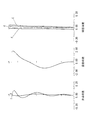
実施例1の撮像レンズについて、数値データを表1に示す。また、図1は撮像レンズの断面図、図2は諸収差図である。 Numerical data of the imaging lens of Example 1 is shown in Table 1. 1 is a sectional view of the imaging lens, and FIG. 2 is a diagram showing various aberrations.

実施例2の撮像レンズについて、数値データを表1に示す。また、図3は撮像レンズの断面図、図4は諸収差図である。 Numerical data of the imaging lens of Example 2 is shown in Table 1. 3 is a sectional view of the imaging lens, and FIG. 4 is a diagram showing various aberrations.
実施例3の撮像レンズについて、数値データを表3に示す。また、図5は撮像レンズの断面図、図6は諸収差図である。 Table 3 shows numerical data of the imaging lens of Example 3. 5 is a sectional view of the imaging lens, and FIG. 6 is a diagram showing various aberrations.
実施例4の撮像レンズについて、数値データを表4に示す。また、図7は撮像レンズの断面図、図8は諸収差図である。 Table 4 shows numerical data of the imaging lens of Example 4. FIG. 7 is a sectional view of the imaging lens, and FIG. 8 is a diagram showing various aberrations.
実施例5の撮像レンズについて、数値データを表5に示す。また、図9は撮像レンズの断面図、図10は諸収差図である。 Numerical data of the imaging lens of Example 5 is shown in Table 5. FIG. 9 is a sectional view of the imaging lens, and FIG. 10 is a diagram showing various aberrations.
実施例6の撮像レンズについて数値データを表6に示す。また、図11は撮像レンズの断面図、図12は諸収差図である。 Table 6 shows numerical data of the imaging lens of Example 6. FIG. 11 is a sectional view of the imaging lens, and FIG. 12 is a diagram showing various aberrations.
実施例1から実施例6に関し、条件式(1)から条件式(10)に対応する値を下記表7に示す。 Regarding Example 1 to Example 6, the values corresponding to Conditional Expression (1) to Conditional Expression (10) are shown in Table 7 below.
表7から明らかなように、条件式(1)から条件式(10)を、実施例1から実施例6の数値データは満足している。 As apparent from Table 7, the numerical data of the conditional expressions (1) to (10) and the numerical expressions of the first to sixth examples are satisfied.
図2、図4、図6、図8、図10、及び図12の諸収差図から明らかなように、各収差共に良好に補正できている。 As is apparent from the aberration diagrams of FIGS. 2, 4, 6, 8, 10, and 12, each aberration can be corrected satisfactorily.
S 開口絞り
L1 第1レンズ
L2 第2レンズ
L3 第3レンズ
L4 第4レンズ
IR 平行平面ガラス
S サジタル像面の収差
T タンジェンシャル像面の収差
F F線における収差
d d線における収差
C C線における収差
S Aperture stop L1 First lens L2 Second lens L3 Third lens L4 Fourth lens IR Parallel plane glass S Aberration of sagittal image plane T Aberration of tangential image plane F Aberration in F line d Aberration in C line aberration
Claims (8)
−1.20<f2/f1<−0.75 (1)
1.00<f3/f1<3.50 (2)
0.16<d12/f<0.25 (3)
0.03<d34/f<0.16 (4)
ただし、
d12:第1レンズと第2レンズの光軸上の空気間隔
d34:第3レンズと第4レンズの光軸上の空気間隔
f1 :第1レンズの焦点距離
f2 :第2レンズの焦点距離
f3 :第3レンズの焦点距離
f :撮像レンズ全系の焦点距離 In order from the object side, a first lens having a positive refractive power, a second lens having a negative refractive power, a convex shape on the object side in the vicinity of the optical axis, a positive refractive power, and light on the image side surface A third lens having an inflection point other than on the axis, and a fourth lens having an inflection point other than on the optical axis on the object side surface having a positive refractive power convex toward the object side near the optical axis And an imaging lens satisfying the following conditional expressions (1), (2), (3), and (4).
−1.20 <f2 / f1 <−0.75 (1)
1.00 <f3 / f1 <3.50 (2)
0.16 <d12 / f <0.25 (3)
0.03 <d34 / f <0.16 (4)
However,
d12: Air spacing on the optical axis of the first lens and the second lens d34: Air spacing on the optical axis of the third lens and the fourth lens f1: Focal length f2 of the first lens: Focal length f3 of the second lens: Focal length f of the third lens: focal length of the entire imaging lens system
2.80<r1r/r1f<4.80 (5)
ただし、
r1r:第1レンズの像側面の曲率半径
r1f:第1レンズの物体側面の曲率半径 The first lens and the second lens are meniscus-shaped, and satisfy the following conditional expression (5) with respect to the curvature radius of the image side surface and the curvature radius of the object side surface of the first lens. The imaging lens described.
2.80 <r1r / r1f <4.80 (5)
However,
r1r: radius of curvature of the image side surface of the first lens r1f: radius of curvature of the object side surface of the first lens
CH3r−CH4f<0 (6)
ただし、
CH3r:第3レンズの像側面における変曲点の光軸からの距離
CH4f:第4レンズの物体側面における変曲点の光軸からの距離 The image side surface of the third lens and the object side surface of the fourth lens have an inflection point other than on the optical axis, and the conditional expression (6) below regarding the position of the inflection point: The imaging lens according to claim 1, wherein:
CH3r-CH4f <0 (6)
However,
CH3r: distance from the optical axis of the inflection point on the image side surface of the third lens CH4f: distance from the optical axis of the inflection point on the object side surface of the fourth lens
45<ν1<60 (7)
22<ν2<35 (8)
1.7<ν1n2/ν2n1<2.8 (9)
ただし、
ν1:第1レンズのd線におけるアッベ数
ν2:第2レンズのd線におけるアッベ数
n1:第1レンズのd線における屈折率
n2:第2レンズのd線における屈折率 The conditional expressions (7), (8) and (9) below are satisfied with respect to the refractive index and the Abbe number of the first lens and the second lens. Imaging lens.
45 <ν1 <60 (7)
22 <ν2 <35 (8)
1.7 <ν1n2 / ν2n1 <2.8 (9)
However,
ν1: Abbe number at the d-line of the first lens ν2: Abbe number at the d-line of the second lens n1: Refractive index at the d-line of the first lens n2: Refractive index at the d-line of the second lens
0.9<d12/d1<2.0 (10)
ただし、
d1:第1レンズの光軸上の厚さ The air condition on the optical axis of the first lens and the second lens and the thickness on the optical axis of the first lens satisfy the following conditional expression (10): , 3 and 4 imaging lens.
0.9 <d12 / d1 <2.0 (10)
However,
d1: Thickness on the optical axis of the first lens
Priority Applications (1)
| Application Number | Priority Date | Filing Date | Title |
|---|---|---|---|
| JP2007339266A JP5069554B2 (en) | 2007-12-28 | 2007-12-28 | Imaging lens |
Applications Claiming Priority (1)
| Application Number | Priority Date | Filing Date | Title |
|---|---|---|---|
| JP2007339266A JP5069554B2 (en) | 2007-12-28 | 2007-12-28 | Imaging lens |
Publications (2)
| Publication Number | Publication Date |
|---|---|
| JP2009162810A JP2009162810A (en) | 2009-07-23 |
| JP5069554B2 true JP5069554B2 (en) | 2012-11-07 |
Family
ID=40965551
Family Applications (1)
| Application Number | Title | Priority Date | Filing Date |
|---|---|---|---|
| JP2007339266A Active JP5069554B2 (en) | 2007-12-28 | 2007-12-28 | Imaging lens |
Country Status (1)
| Country | Link |
|---|---|
| JP (1) | JP5069554B2 (en) |
Families Citing this family (8)
| Publication number | Priority date | Publication date | Assignee | Title |
|---|---|---|---|---|
| WO2011027690A1 (en) * | 2009-09-02 | 2011-03-10 | コニカミノルタオプト株式会社 | Single-focus optical system, image pickup device, and digital apparatus |
| JP5397538B2 (en) * | 2010-03-26 | 2014-01-22 | コニカミノルタ株式会社 | Imaging lens, imaging optical device, and digital device |
| KR101933960B1 (en) * | 2011-10-21 | 2019-04-05 | 엘지이노텍 주식회사 | Imaging lens |
| TWI471588B (en) | 2012-12-28 | 2015-02-01 | 玉晶光電股份有限公司 | Portable electronic device and optical imaging lens thereof |
| TWI546561B (en) | 2014-12-01 | 2016-08-21 | 先進光電科技股份有限公司 | Optical image capturing system |
| CN113741010A (en) * | 2017-08-08 | 2021-12-03 | 玉晶光电(厦门)有限公司 | Optical imaging lens |
| CN110596856B (en) * | 2019-08-16 | 2021-07-30 | 诚瑞光学(常州)股份有限公司 | Camera optics |
| CN110488462B (en) * | 2019-08-16 | 2021-08-20 | 诚瑞光学(常州)股份有限公司 | Camera optics |
Family Cites Families (1)
| Publication number | Priority date | Publication date | Assignee | Title |
|---|---|---|---|---|
| JP4828317B2 (en) * | 2005-09-29 | 2011-11-30 | 富士フイルム株式会社 | Imaging lens |
-
2007
- 2007-12-28 JP JP2007339266A patent/JP5069554B2/en active Active
Also Published As
| Publication number | Publication date |
|---|---|
| JP2009162810A (en) | 2009-07-23 |
Similar Documents
| Publication | Publication Date | Title |
|---|---|---|
| JP5665229B2 (en) | Imaging lens | |
| JP5975386B2 (en) | Imaging lens | |
| JP5095662B2 (en) | Imaging lens for solid-state imaging device | |
| JP5317480B2 (en) | Imaging lens | |
| JP4947423B2 (en) | Imaging lens | |
| JP5992868B2 (en) | Imaging device | |
| JP5334688B2 (en) | Imaging lens for solid-state imaging device | |
| US7532415B2 (en) | Imaging lens | |
| CN204178038U (en) | Pick-up lens | |
| JP5894847B2 (en) | Imaging lens | |
| JP6377096B2 (en) | Imaging lens | |
| JP5797007B2 (en) | Imaging lens for solid-state imaging device | |
| JP5069554B2 (en) | Imaging lens | |
| JP2014160158A (en) | Imaging lens, imaging apparatus, and portable terminal | |
| JP2013015587A (en) | Imaging lens | |
| JP2005345919A (en) | Imaging lens | |
| JP2005316010A (en) | Imaging lens | |
| WO2013018748A1 (en) | Imaging lens | |
| JP2006047858A (en) | Imaging lens | |
| JP4431487B2 (en) | Imaging lens and imaging module including the same | |
| JP2006309043A (en) | Imaging lens | |
| JP5308915B2 (en) | Imaging lens | |
| JP2013167903A (en) | Imaging lens for solid-state imaging element | |
| JP2006084720A (en) | Imaging lens | |
| JP2006220691A (en) | Imaging lens |
Legal Events
| Date | Code | Title | Description |
|---|---|---|---|
| A621 | Written request for application examination |
Free format text: JAPANESE INTERMEDIATE CODE: A621 Effective date: 20101203 |
|
| TRDD | Decision of grant or rejection written | ||
| A01 | Written decision to grant a patent or to grant a registration (utility model) |
Free format text: JAPANESE INTERMEDIATE CODE: A01 Effective date: 20120807 |
|
| A01 | Written decision to grant a patent or to grant a registration (utility model) |
Free format text: JAPANESE INTERMEDIATE CODE: A01 |
|
| A977 | Report on retrieval |
Free format text: JAPANESE INTERMEDIATE CODE: A971007 Effective date: 20120808 |
|
| A61 | First payment of annual fees (during grant procedure) |
Free format text: JAPANESE INTERMEDIATE CODE: A61 Effective date: 20120817 |
|
| FPAY | Renewal fee payment (event date is renewal date of database) |
Free format text: PAYMENT UNTIL: 20150824 Year of fee payment: 3 |
|
| R150 | Certificate of patent or registration of utility model |
Free format text: JAPANESE INTERMEDIATE CODE: R150 Ref document number: 5069554 Country of ref document: JP Free format text: JAPANESE INTERMEDIATE CODE: R150 |
|
| R250 | Receipt of annual fees |
Free format text: JAPANESE INTERMEDIATE CODE: R250 |
|
| R250 | Receipt of annual fees |
Free format text: JAPANESE INTERMEDIATE CODE: R250 |
|
| R250 | Receipt of annual fees |
Free format text: JAPANESE INTERMEDIATE CODE: R250 |
|
| S531 | Written request for registration of change of domicile |
Free format text: JAPANESE INTERMEDIATE CODE: R313531 |
|
| R350 | Written notification of registration of transfer |
Free format text: JAPANESE INTERMEDIATE CODE: R350 |
|
| R250 | Receipt of annual fees |
Free format text: JAPANESE INTERMEDIATE CODE: R250 |
|
| R250 | Receipt of annual fees |
Free format text: JAPANESE INTERMEDIATE CODE: R250 |
|
| S111 | Request for change of ownership or part of ownership |
Free format text: JAPANESE INTERMEDIATE CODE: R313113 |
|
| R371 | Transfer withdrawn |
Free format text: JAPANESE INTERMEDIATE CODE: R371 |
|
| S111 | Request for change of ownership or part of ownership |
Free format text: JAPANESE INTERMEDIATE CODE: R313113 |
|
| R350 | Written notification of registration of transfer |
Free format text: JAPANESE INTERMEDIATE CODE: R350 |
|
| R250 | Receipt of annual fees |
Free format text: JAPANESE INTERMEDIATE CODE: R250 |
|
| R250 | Receipt of annual fees |
Free format text: JAPANESE INTERMEDIATE CODE: R250 |
|
| R250 | Receipt of annual fees |
Free format text: JAPANESE INTERMEDIATE CODE: R250 |