JP5044372B2 - Magnetostrictive torque sensor shaft manufacturing method - Google Patents
Magnetostrictive torque sensor shaft manufacturing method Download PDFInfo
- Publication number
- JP5044372B2 JP5044372B2 JP2007298106A JP2007298106A JP5044372B2 JP 5044372 B2 JP5044372 B2 JP 5044372B2 JP 2007298106 A JP2007298106 A JP 2007298106A JP 2007298106 A JP2007298106 A JP 2007298106A JP 5044372 B2 JP5044372 B2 JP 5044372B2
- Authority
- JP
- Japan
- Prior art keywords
- torque sensor
- magnetostrictive film
- sensor shaft
- magnetostrictive
- hole
- Prior art date
- Legal status (The legal status is an assumption and is not a legal conclusion. Google has not performed a legal analysis and makes no representation as to the accuracy of the status listed.)
- Expired - Fee Related
Links
Images


Landscapes
- Power Steering Mechanism (AREA)
Description
本発明は、トルクセンサシャフト本体の外周面部に磁歪膜を設けると共に、その磁歪膜に軸方向に対して傾斜する磁歪膜削除パターンを設けて成る磁歪式トルクセンサシャフトの製造方法に関する。 The present invention relates to a method for manufacturing a magnetostrictive torque sensor shaft in which a magnetostrictive film is provided on an outer peripheral surface portion of a torque sensor shaft main body and a magnetostrictive film deletion pattern that is inclined with respect to the axial direction is provided on the magnetostrictive film.
従来より、トルクの検出をするトルクセンサとして、トルクセンサシャフト本体の外周面部に磁歪膜を設けて成る磁歪式トルクセンサシャフトを具え、このトルクセンサシャフトの磁歪膜を設けた部分の外周にコイルを配置した構成にて、トルクセンサシャフトに作用するトルクにより、上記磁歪膜に引張りや圧縮の応力が及び、それによる逆磁歪効果で磁歪膜の透磁率が変化することに応じ、その透磁率変化をコイルにより検出するものが供されている。 Conventionally, as a torque sensor for detecting torque, a magnetostrictive torque sensor shaft having a magnetostrictive film provided on the outer peripheral surface portion of a torque sensor shaft main body has been provided, and a coil is provided on the outer periphery of the portion of the torque sensor shaft provided with the magnetostrictive film. In the arranged configuration, the tensile force or compressive stress is applied to the magnetostrictive film due to the torque acting on the torque sensor shaft, and the permeability change of the magnetostrictive film due to the inverse magnetostrictive effect thereby changes the permeability. What is detected by a coil is provided.
そして又、このものにおいては、上記磁歪膜に、軸方向に対して傾斜する磁歪膜削除パターンを設けたものが供されており、このものでは、その磁歪膜削除パターンの傾斜に応じて、トルクセンサシャフトに作用するトルクによる引張りや圧縮の応力が磁歪膜に効果的に及ぶことから、磁歪膜の透磁率変化が大きく、トルクの検出精度が高く得られる。 In this case, the magnetostrictive film is provided with a magnetostrictive film deletion pattern that is inclined with respect to the axial direction. In this case, torque is applied in accordance with the inclination of the magnetostrictive film deletion pattern. Since the tensile or compressive stress due to the torque acting on the sensor shaft is effectively applied to the magnetostrictive film, the permeability change of the magnetostrictive film is large, and the torque detection accuracy is high.
しかして、このもののトルクセンサシャフトの製造方法としては、例えば、磁歪材であるアモルファス薄帯に、楕円形の孔をトルクセンサシャフト本体の軸方向に対し傾斜状に並べて複数個穿つことにより磁歪膜削除パターンを形成し、この磁歪膜削除パターンを形成したアモルファス薄帯をトルクセンサシャフト本体の外周面部に接着する方法がある(例えば特許文献1参照)。 Therefore, as a method of manufacturing the torque sensor shaft of this type, for example, a magnetostrictive film is formed by drilling a plurality of elliptical holes arranged in an inclined manner with respect to the axial direction of the torque sensor shaft body in an amorphous ribbon that is a magnetostrictive material. There is a method in which a deletion pattern is formed and an amorphous ribbon having the magnetostrictive film deletion pattern is adhered to the outer peripheral surface portion of the torque sensor shaft main body (for example, see Patent Document 1).
又、上記とは異なるトルクセンサシャフトの製造方法として、トルクセンサシャフト本体の外周面部に磁歪膜を磁性薄板の接着又はメッキで設け、その磁歪膜に、軸方向に対し傾斜して連続する溝をエッチングやレーザトリミングによって形成することにより磁歪膜削除パターンを設ける方法がある。(例えば特許文献2参照)。
上記従来のもののうち、前者(特許文献1による方法)では、トルクセンサシャフト本体の外周面部に接着する前の薄帯に孔をトルクセンサシャフト本体の軸方向に対し傾斜状に並べて複数個穿つ作業が困難であり、又、そのようにして磁歪膜削除パターンを形成したアモルファス薄帯をトルクセンサシャフト本体の外周面部に接着するのも困難であった。 Among the above conventional methods, in the former (method according to Patent Document 1), a plurality of holes are formed in the thin ribbon before being bonded to the outer peripheral surface portion of the torque sensor shaft main body so as to be inclined with respect to the axial direction of the torque sensor shaft main body. In addition, it has been difficult to bond the amorphous ribbon having the magnetostrictive film deletion pattern thus formed to the outer peripheral surface portion of the torque sensor shaft body.
そして一方、後者(特許文献2による方法)では、トルクセンサシャフト本体の外周面部に磁性薄板の接着又はメッキで設けた磁歪膜に、軸方向に対し傾斜して連続する溝をエッチングやレーザトリミングによって形成するのが困難で、特にエッチングでは、トルクセンサシャフト本体の外周面部にその円筒面に沿って磁歪膜を残す(連続溝を形成する)マスキングを施すのが困難であり、又、レーザトリミングでは、トルクセンサシャフト本体の外周面部に設けた磁歪膜を連続する溝で削除するのに、トルクセンサシャフト本体(ワーク)を回転させつつレーザを照射するが、そのレーザ出力の管理やトルクセンサシャフト本体の回転速度の管理が困難であった。 On the other hand, in the latter (method according to Patent Document 2), a groove that is inclined and continuous with respect to the axial direction is formed by etching or laser trimming on a magnetostrictive film provided on the outer peripheral surface of the torque sensor shaft body by adhesion or plating of a magnetic thin plate. It is difficult to form, especially in etching, it is difficult to mask the outer peripheral surface portion of the torque sensor shaft main body so as to leave a magnetostrictive film along the cylindrical surface (form a continuous groove), and in laser trimming, In order to remove the magnetostrictive film provided on the outer peripheral surface of the torque sensor shaft main body with a continuous groove, the laser is irradiated while rotating the torque sensor shaft main body (work), but the management of the laser output and the torque sensor shaft main body It was difficult to manage the rotation speed.
本発明は上述の事情に鑑みてなされたものであり、従ってその目的は、トルクセンサシャフト本体の外周面部に設ける磁歪膜に、軸方向に対して傾斜する磁歪膜削除パターンを容易に設けることのできる磁歪式トルクセンサシャフトの製造方法を提供するにある。 The present invention has been made in view of the above-described circumstances. Therefore, the object of the present invention is to easily provide a magnetostrictive film deletion pattern inclined on the axial direction on the magnetostrictive film provided on the outer peripheral surface portion of the torque sensor shaft body. Another object of the present invention is to provide a method for manufacturing a magnetostrictive torque sensor shaft.
上記目的を達成するために、本発明の磁歪式トルクセンサシャフトの製造方法においては、トルクセンサシャフト本体の外周面部に磁歪膜を設け、その後に、その磁歪膜にほゞ円形の孔を、レーザトリミングによって、軸方向に対し傾斜状に並べて複数個穿つことにより磁歪膜削除パターンを形成するようにしたことを特徴とする(請求項1の発明)。 To achieve the above object, in the method for manufacturing a magnetostrictive torque sensor shaft of the present invention, a magnetostrictive film provided on the outer peripheral surface of a torque sensor shaft body, after which the magnetostrictive film ho Isuzu circular hole, laser A plurality of magnetostrictive film deletion patterns are formed by trimming and forming a plurality of holes in an inclined manner with respect to the axial direction (invention of claim 1).
上記手段によれば、トルクセンサシャフト本体の外周面部に接着する前の薄帯に孔をトルクセンサシャフト本体の軸方向に対し傾斜状に並べて複数個穿つような作業の困難さがなく、又、そのようにして磁歪膜削除パターンを形成したアモルファス薄帯をトルクセンサシャフト本体の外周面部に接着するような作業の困難さもない。更に、孔はほゞ円形であって溝ではないから、トルクセンサシャフト本体の外周面部にその円筒面に沿って磁歪膜を残す(連続溝を形成する)マスキングを施すような作業の困難さがない上、レーザトリミングをする場合のレーザ出力の管理やトルクセンサシャフト本体の回転速度の管理も容易である。 According to the above means, there is no difficulty in the work of drilling a plurality of holes arranged in an inclined manner with respect to the axial direction of the torque sensor shaft body in the ribbon before bonding to the outer peripheral surface portion of the torque sensor shaft body, There is no difficulty in the work of adhering the amorphous ribbon having the magnetostrictive film deletion pattern to the outer peripheral surface portion of the torque sensor shaft main body. Further, since the hole is substantially circular and not a groove, it is difficult to carry out masking on the outer peripheral surface portion of the torque sensor shaft main body so as to leave a magnetostrictive film along the cylindrical surface (form a continuous groove). In addition, it is easy to manage the laser output and the rotational speed of the torque sensor shaft body when performing laser trimming.
以下、本発明の第1実施例(第1の実施形態)につき、図1ないし図6を参照して説明する。
まず、図6には、トルクセンサ1の全体構造を示しており、中央に磁歪式トルクセンサシャフト2が存している。この磁歪式トルクセンサシャフト2は、ステンレス鋼など金属にて円柱状に形成したトルクセンサシャフト本体3と、これの図中左右方向の中間部の近接した二箇所にわたってその表面に設けた磁歪膜4、及びこの磁歪膜4に軸方向に対し左右対称的に傾斜させて設けた磁歪膜削除パターン5から成っており、その詳細は後述する。
A first embodiment (first embodiment) of the present invention will be described below with reference to FIGS.
First, FIG. 6 shows the overall structure of the torque sensor 1, and the magnetostrictive
磁歪式トルクセンサシャフトの上記磁歪膜4を設けた部分の外周囲には、それぞれ検出コイル6をボビン7に巻装した状態で配設している。ボビン7には、導電材から成る2本(図で上下)の接続ピン8を挿通して固着しており、この接続ピン8のボビン7内側部分に、各検出コイル6の先端部を接続している。
A
トルクセンサシャフト本体3の磁歪膜4を設けた部分の両側には、軸受9をそれぞれ装着し、これらの両軸受9からボビン7にかけて、フレーム10を被装している。このフレーム10の図中左側部の外側には、各種電気部品11を実装した中継用基板12を装着しており、この中継用基板12に、フレーム10から突出させた前記接続ピン8の各先端部を挿通させて半田付け等により接続している。
Bearings 9 are mounted on both sides of the portion of the torque
なお、中継用基板12に実装した各種電気部品11は、検出コイル6と協働して、磁歪式トルクセンサシャフトに作用したトルクを検出するもので、磁歪式トルクセンサシャフトに作用したトルクにより及ぶ応力で磁歪膜4の透磁率が変化することに応じ、その透磁率変化を検出することで、磁歪式トルクセンサシャフトに作用したトルクを検出するようになっている。
The various
ここで、磁歪式トルクセンサシャフト2の製造方法につき詳述するに、まず、図2に示すように、前記トルクセンサシャフト本体3の中間部の近接した二箇所にわたってその表面には、例えばニッケルと鉄との合金から成る磁歪膜4をメッキ、特には湿式メッキによって帯状に設ける。その厚さ(図5にEで示す)は、例えば数〔μm〕〜数10〔μm〕である。
Here, the manufacturing method of the magnetostrictive
次いで、図3に示すように、上記磁歪膜4にほゞ円形の孔13をトルクセンサシャフト本体3の軸方向に対し左右対称の傾斜状に並べて複数個穿つことにより、同傾斜状の前記磁歪膜削除パターン5を形成する。この場合、詳細には、孔13は、磁歪膜4にレーザを照射するレーザトリミングによって穿つもので、そのレーザの照射は例えば直径が数〔μm〕のスポット照射で行う。孔13の直径は、数10〔μm〕である。又、孔13の傾斜並び(磁歪膜削除パターン5)の傾斜角度αは、この場合、最も好ましいほゞ45度である。
Next, as shown in FIG. 3, a plurality of substantially
上記レーザトリミングによる孔13の形成は、図4に矢印と併せて示す番号順に行うもので、すなわち、1つの孔13を形成した後に、隣の孔13の部分避けて形成する順序で行う。
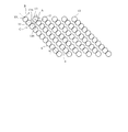
図1は、上述のようにして磁歪膜4に形成した孔13の部分を拡大して表しており、この孔13は傾斜の並び方向に重なっておらず、その並び方向に隣り合う二つの孔の中心間距離Aは、隣り合う磁歪膜削除パターン5の中心間距離Bより小さく(A<B)している。
The
FIG. 1 is an enlarged view of the portion of the
又、孔13の中心Oは、隣の磁歪膜削除パターン5の二つの孔13間の中央からの垂直二等分線C上に位置するようにしている。
図5は、孔13の深さDを示しており、この孔13の深さDは磁歪膜4の厚みEとほゞ同一(D≒E)としていて、それは又、トルクセンサシャフト本体3にかかった孔13の底部における直径fが、孔13の磁歪膜4表面部における直径Fの1/2以上(f≧F/2)となるのを好ましい値としている。
The center O of the
FIG. 5 shows the depth D of the
このように本構成のものでは、トルクセンサシャフト本体3の外周面部に磁歪膜4を設け、その後に、その磁歪膜4にほゞ円形の孔13を軸方向に対し傾斜状に並べて複数個穿つことにより磁歪膜削除パターン5を形成することで、磁歪式トルクセンサシャフト2を製造するようにしている。
As described above, in this configuration, the
この方法によれば、磁歪膜4には、それをトルクセンサシャフト本体3の外周面部に設けた後に、孔13をトルクセンサシャフト本体3の軸方向に対し傾斜状に並べて複数個穿つのであるから、従来の、トルクセンサシャフト本体の外周面部に接着する前の薄帯に孔をトルクセンサシャフト本体の軸方向に対し傾斜状に並べて複数個穿つような作業の困難さがなく、又、そのようにして磁歪膜削除パターンを形成したアモルファス薄帯をトルクセンサシャフト本体の外周面部に接着するような作業の困難さもない。
According to this method, since the
又、孔13はほゞ円形であって溝ではないから、従来の、トルクセンサシャフト本体の外周面部にその円筒面に沿って磁歪膜を残す(連続溝を形成する)マスキングを施すような作業の困難さがない上、レーザトリミングをする場合のレーザ出力の管理やトルクセンサシャフト本体の回転速度の管理も容易にできる。
かくして、本構成のものの場合、トルクセンサシャフト本体3の外周面部に設ける磁歪膜4に、軸方向に対して傾斜する磁歪膜削除パターン5を容易に設けることができる。
Further, since the
Thus, in the case of this configuration, the magnetostrictive
特に、本構成のものの場合、孔13は傾斜の並び方向に重なっていないが、その並び方向に隣り合う二つの孔の中心間距離Aは、隣り合う磁歪膜削除パターン5の中心間距離Bより小さくしている。それにより、磁歪膜削除パターン5と、残った磁歪膜4のパターンとの区別が明確となり、それだけトルクセンサシャフトにトルクが作用したときの磁歪膜4の透磁率変化を明確に出させることができて、トルクの検出精度を高めることができ、且つ、磁歪膜4のパターンを幅広く残すことができて、磁歪膜4の固着強度を高め、使用上の信頼性を向上させることができる。
In particular, in the case of this configuration, the
又、孔13の中心Oは、隣の磁歪膜削除パターン5の二つの孔13間の中央からの垂直二等分線C上に位置するようにしており、それによって、その垂直二等分線C上には、磁歪膜削除パターン5の孔13の外形上の凸形状(図1に13aで示す)が隣の磁歪膜削除パターン5の二つの孔13間の凹形状(図1に13bで示す)に合って、磁歪膜4を極力外形の凹凸の少ない形状に残すことができ、それだけ又、トルクセンサシャフトにトルクが作用したときの磁歪膜4の透磁率変化を明確に出させることができて、トルクの検出精度を高めることができる。
The center O of the
更に、孔13の深さDは磁歪膜4の厚みEとほゞ同一としており、それによって、磁歪膜削除パターン5と、残った磁歪膜4のパターンとの区別を明確にするのに、磁歪膜4を穿つのがほゞ必要最小限の加工でできる。
Further, the depth D of the
そして、孔13はレーザトリミングによって形成しており、レーザトリミングはレーザのスポット照射の直径を数〔μm〕に絞って行い得るから、孔13も数10〔μm〕の微細な直径で形成できて、磁歪膜削除パターン5を微細なパターンに形成でき、それだけトルクセンサシャフト本体3に対するパターン本数を多くできるから、磁歪膜4の透磁率変化を豊富にしてトルクの検出精度を高めることができる。しかも、レーザトリミングの熱により磁歪膜4とトルクセンサシャフト本体3とを溶接結合する作用もあって、磁歪膜4をトルクセンサシャフト本体3により強固に固着することができ、使用上の信頼性を向上させることができる。
The
加えて、この場合、孔13は、レーザトリミングにより、1つの孔13を形成した後には、隣りの孔13の部分を避けて形成するようにしており、それによって、レーザトリミングによる加工熱が分散して与えられ、均一な熱加工ができる。又、その加工時に磁歪膜4が過度に加熱されると、孔13の径に狂いが生じることがあるが、レーザトリミングによる加工熱が分散して与えられ、磁歪膜4が過度に加熱されることがないので、孔13の径に狂いが生じることもない。
In addition, in this case, after forming one
以上に対して、図7は本発明の第2実施例(第2の実施形態)を示すもので、第1実施例と同一の部分には同一の符号を付して説明を省略し、異なる部分についてのみ述べる。 In contrast to this, FIG. 7 shows a second embodiment (second embodiment) of the present invention. The same parts as those in the first embodiment are denoted by the same reference numerals, and the description thereof is omitted. Only the part is described.
このものの場合、磁歪膜削除パターン5の孔13を傾斜の並び方向に一部ずつ重ねて形成している。
このようにすることにより、磁歪膜削除パターン5と、残った磁歪膜4のパターンとの区別が一層明確となり、それだけトルクセンサシャフトにトルクが作用したときの磁歪膜4の透磁率変化を一層明確に出させることができて、トルクの検出精度を更に高めることができる。
そのほかは、第1実施例と同一であり、従って、第1実施例と同様の作用効果を得ることができる。
In this case, the
By doing so, the distinction between the magnetostrictive
Other than that, this embodiment is the same as the first embodiment, and therefore the same effects as the first embodiment can be obtained.
このほか、本発明は上記し且つ図面に示した実施例にのみ限定されるものではなく、要旨を逸脱しない範囲内で適宜変更して実施し得る。 In addition, the present invention is not limited to the embodiments described above and shown in the drawings, and can be implemented with appropriate modifications without departing from the scope of the invention.
図面中、1はトルクセンサ、2は磁歪式トルクセンサシャフト、3はトルクセンサシャフト本体、4は磁歪膜、5は磁歪膜削除パターン、13は孔、Aは二つの孔の中心間距離、Bは隣り合う磁歪膜削除パターンの中心間距離、Cは二つの孔間の中央からの垂直二等分線、Dは孔の深さ、Eは磁歪膜の厚み、Oは孔の中心を示す。 In the drawings, 1 is a torque sensor, 2 is a magnetostrictive torque sensor shaft, 3 is a torque sensor shaft body, 4 is a magnetostrictive film, 5 is a magnetostrictive film deletion pattern, 13 is a hole, A is a distance between centers of two holes, B Is the distance between the centers of adjacent magnetostrictive film deletion patterns, C is a perpendicular bisector from the center between two holes, D is the depth of the hole, E is the thickness of the magnetostrictive film, and O is the center of the hole.
Claims (6)
Priority Applications (1)
| Application Number | Priority Date | Filing Date | Title |
|---|---|---|---|
| JP2007298106A JP5044372B2 (en) | 2007-11-16 | 2007-11-16 | Magnetostrictive torque sensor shaft manufacturing method |
Applications Claiming Priority (1)
| Application Number | Priority Date | Filing Date | Title |
|---|---|---|---|
| JP2007298106A JP5044372B2 (en) | 2007-11-16 | 2007-11-16 | Magnetostrictive torque sensor shaft manufacturing method |
Publications (2)
| Publication Number | Publication Date |
|---|---|
| JP2009122042A JP2009122042A (en) | 2009-06-04 |
| JP5044372B2 true JP5044372B2 (en) | 2012-10-10 |
Family
ID=40814346
Family Applications (1)
| Application Number | Title | Priority Date | Filing Date |
|---|---|---|---|
| JP2007298106A Expired - Fee Related JP5044372B2 (en) | 2007-11-16 | 2007-11-16 | Magnetostrictive torque sensor shaft manufacturing method |
Country Status (1)
| Country | Link |
|---|---|
| JP (1) | JP5044372B2 (en) |
Cited By (1)
| Publication number | Priority date | Publication date | Assignee | Title |
|---|---|---|---|---|
| WO2024224880A1 (en) | 2023-04-25 | 2024-10-31 | 臼井国際産業株式会社 | Magnetostrictive torque sensor shaft |
Families Citing this family (7)
| Publication number | Priority date | Publication date | Assignee | Title |
|---|---|---|---|---|
| EP3458805B1 (en) | 2016-05-17 | 2020-09-23 | Kongsberg Inc. | System, method and object for high accuracy magnetic position sensing |
| WO2018109674A1 (en) | 2016-12-12 | 2018-06-21 | Kongsberg Inc. | Dual-band magnetoelastic torque sensor |
| US10983019B2 (en) | 2019-01-10 | 2021-04-20 | Ka Group Ag | Magnetoelastic type torque sensor with temperature dependent error compensation |
| MX2022002951A (en) | 2019-09-13 | 2022-05-10 | Ka Group Ag | Magnetoelastic torque sensor assembly for reducing magnetic error due to harmonics. |
| US12281951B2 (en) | 2020-02-11 | 2025-04-22 | Brp Megatech Industries Inc. | Magnetoelastic torque sensor with local measurement of ambient magnetic field |
| JP2021148556A (en) * | 2020-03-18 | 2021-09-27 | 臼井国際産業株式会社 | Shaft for magnetostrictive torque sensor and method for measuring the same |
| WO2021187477A1 (en) * | 2020-03-18 | 2021-09-23 | 臼井国際産業株式会社 | Method for forming magnetostrictive material-coated pattern of magnetostriction type torque sensor shaft, and magnetostriction type torque sensor shaft |
Family Cites Families (6)
| Publication number | Priority date | Publication date | Assignee | Title |
|---|---|---|---|---|
| JPS62159022A (en) * | 1986-01-08 | 1987-07-15 | Matsushita Electric Ind Co Ltd | torque sensor |
| JP2516772B2 (en) * | 1987-07-21 | 1996-07-24 | 三菱電機株式会社 | Method of manufacturing stress detector |
| JPH0552678A (en) * | 1991-08-26 | 1993-03-02 | Hitachi Powdered Metals Co Ltd | Magnetostriction detector for magnetostriction torque sensor and manufacture thereof |
| JP4683736B2 (en) * | 2001-01-30 | 2011-05-18 | 京セラ株式会社 | Drilling method |
| JP2004184190A (en) * | 2002-12-02 | 2004-07-02 | Yamaha Motor Co Ltd | Magnetostrictive torque sensor |
| JP2004184188A (en) * | 2002-12-02 | 2004-07-02 | Yamaha Motor Co Ltd | Magnetostrictive torque sensor |
-
2007
- 2007-11-16 JP JP2007298106A patent/JP5044372B2/en not_active Expired - Fee Related
Cited By (2)
| Publication number | Priority date | Publication date | Assignee | Title |
|---|---|---|---|---|
| WO2024224880A1 (en) | 2023-04-25 | 2024-10-31 | 臼井国際産業株式会社 | Magnetostrictive torque sensor shaft |
| EP4703697A1 (en) | 2023-04-25 | 2026-03-04 | Usui Co., Ltd. | Magnetostrictive torque sensor shaft |
Also Published As
| Publication number | Publication date |
|---|---|
| JP2009122042A (en) | 2009-06-04 |
Similar Documents
| Publication | Publication Date | Title |
|---|---|---|
| JP5044372B2 (en) | Magnetostrictive torque sensor shaft manufacturing method | |
| JP5943658B2 (en) | Terminal structure, flexure, and head suspension | |
| US20090261060A1 (en) | Production Method of Suspension Board with Circuit | |
| JP4865453B2 (en) | Wiring circuit board and manufacturing method thereof | |
| JP6656224B2 (en) | Suction roll with sensor for detecting operating parameters | |
| JP2010098098A (en) | Method of manufacturing electronic apparatus | |
| JP6872960B2 (en) | Electrical connection device | |
| JP4640802B2 (en) | Suspension board with circuit | |
| JP5528273B2 (en) | Wiring circuit board, wiring circuit board assembly sheet, and method for manufacturing the same | |
| CN105096969B (en) | Terminal pad for head gimbals and the method that forms the terminal pad | |
| US5142919A (en) | Magnetostriction type stress detector | |
| KR100946867B1 (en) | Method for Manufacturing Semiconductor Optical Device and Semiconductor Optical Device | |
| JP2007158249A (en) | Wiring circuit board and manufacturing method thereof | |
| JP4887749B2 (en) | Resistor manufacturing method | |
| JP2008277508A (en) | Flexible circuit board, motor including the same, and hard disk drive device | |
| JP2017107622A (en) | Suspension board with circuit and method for manufacturing suspension board with circuit | |
| JP2006228988A (en) | Flexible substrate | |
| JP5131320B2 (en) | Suspension substrate and manufacturing method thereof | |
| JP2002269714A (en) | HEAD SUSPENSION ASSEMBLY MANUFACTURING METHOD AND HEAD SUSPENSION ASSEMBLY | |
| JP2002050017A (en) | Magnetic head device, and method and device for manufacturing the same | |
| JP2006010588A (en) | Contact probe and manufacturing method thereof | |
| JP5789882B2 (en) | Manufacturing method of cylindrical current fuse | |
| JP5303772B2 (en) | Contact structure and contact mounting method | |
| JP4723275B2 (en) | Semiconductor device and manufacturing method of semiconductor device | |
| JP2005164247A (en) | Fatigue sensor and method for manufacturing the same, fragment of fatigue sensor and method for manufacturing the same |
Legal Events
| Date | Code | Title | Description |
|---|---|---|---|
| A621 | Written request for application examination |
Free format text: JAPANESE INTERMEDIATE CODE: A621 Effective date: 20090928 |
|
| A131 | Notification of reasons for refusal |
Free format text: JAPANESE INTERMEDIATE CODE: A131 Effective date: 20111115 |
|
| A977 | Report on retrieval |
Free format text: JAPANESE INTERMEDIATE CODE: A971007 Effective date: 20111116 |
|
| A521 | Written amendment |
Free format text: JAPANESE INTERMEDIATE CODE: A523 Effective date: 20120113 |
|
| TRDD | Decision of grant or rejection written | ||
| A01 | Written decision to grant a patent or to grant a registration (utility model) |
Free format text: JAPANESE INTERMEDIATE CODE: A01 Effective date: 20120619 |
|
| A01 | Written decision to grant a patent or to grant a registration (utility model) |
Free format text: JAPANESE INTERMEDIATE CODE: A01 |
|
| A61 | First payment of annual fees (during grant procedure) |
Free format text: JAPANESE INTERMEDIATE CODE: A61 Effective date: 20120713 |
|
| R150 | Certificate of patent or registration of utility model |
Ref document number: 5044372 Country of ref document: JP Free format text: JAPANESE INTERMEDIATE CODE: R150 Free format text: JAPANESE INTERMEDIATE CODE: R150 |
|
| FPAY | Renewal fee payment (event date is renewal date of database) |
Free format text: PAYMENT UNTIL: 20150720 Year of fee payment: 3 |
|
| S111 | Request for change of ownership or part of ownership |
Free format text: JAPANESE INTERMEDIATE CODE: R313117 Free format text: JAPANESE INTERMEDIATE CODE: R313115 |
|
| S531 | Written request for registration of change of domicile |
Free format text: JAPANESE INTERMEDIATE CODE: R313531 |
|
| S533 | Written request for registration of change of name |
Free format text: JAPANESE INTERMEDIATE CODE: R313533 |
|
| R350 | Written notification of registration of transfer |
Free format text: JAPANESE INTERMEDIATE CODE: R350 |
|
| LAPS | Cancellation because of no payment of annual fees |