JP5032533B2 - Frame transmission apparatus and frame discard number measuring method - Google Patents
Frame transmission apparatus and frame discard number measuring method Download PDFInfo
- Publication number
- JP5032533B2 JP5032533B2 JP2009138091A JP2009138091A JP5032533B2 JP 5032533 B2 JP5032533 B2 JP 5032533B2 JP 2009138091 A JP2009138091 A JP 2009138091A JP 2009138091 A JP2009138091 A JP 2009138091A JP 5032533 B2 JP5032533 B2 JP 5032533B2
- Authority
- JP
- Japan
- Prior art keywords
- frame
- transmission
- maintenance
- frames
- physical link
- Prior art date
- Legal status (The legal status is an assumption and is not a legal conclusion. Google has not performed a legal analysis and makes no representation as to the accuracy of the status listed.)
- Expired - Fee Related
Links
- 230000005540 biological transmission Effects 0.000 title claims description 241
- 238000000034 method Methods 0.000 title claims description 71
- 238000012423 maintenance Methods 0.000 claims description 112
- 230000002776 aggregation Effects 0.000 claims description 86
- 238000004220 aggregation Methods 0.000 claims description 86
- 230000008569 process Effects 0.000 claims description 59
- 238000012545 processing Methods 0.000 claims description 30
- 230000007246 mechanism Effects 0.000 claims description 17
- 238000000691 measurement method Methods 0.000 claims 1
- 230000006870 function Effects 0.000 description 34
- 238000004891 communication Methods 0.000 description 17
- 238000005259 measurement Methods 0.000 description 12
- 238000010586 diagram Methods 0.000 description 8
- 238000012360 testing method Methods 0.000 description 6
- 238000012546 transfer Methods 0.000 description 4
- 238000012544 monitoring process Methods 0.000 description 3
- 230000004044 response Effects 0.000 description 2
- 241001522296 Erithacus rubecula Species 0.000 description 1
- 238000004364 calculation method Methods 0.000 description 1
- 230000008094 contradictory effect Effects 0.000 description 1
- 230000007423 decrease Effects 0.000 description 1
- 238000001514 detection method Methods 0.000 description 1
- 238000003780 insertion Methods 0.000 description 1
- 230000037431 insertion Effects 0.000 description 1
- 238000012986 modification Methods 0.000 description 1
- 230000004048 modification Effects 0.000 description 1
- 230000002123 temporal effect Effects 0.000 description 1
- 230000007704 transition Effects 0.000 description 1
Images


Landscapes
- Data Exchanges In Wide-Area Networks (AREA)
- Maintenance And Management Of Digital Transmission (AREA)
Description
本発明は、複数のフレーム伝送装置をネットワークにより接続し、設定したフレームの送受信点間のフレーム伝送に於けるフレーム廃棄数を測定して、フレーム伝送径路の信頼性を運用中に於いても監視可能とするフレーム伝送装置及びフレーム廃棄数測定方法に関する。 The present invention connects a plurality of frame transmission apparatuses via a network, measures the number of frame discards in frame transmission between the set frame transmission / reception points, and monitors the reliability of the frame transmission path even during operation. The present invention relates to a frame transmission apparatus and a method for measuring the number of discarded frames.
ネットワークを介して複数のフレーム伝送装置を接続し、フレーム伝送装置に接続した端末間でネットワークを介してフレーム伝送を行う場合、送信する宛先アドレスと、送信元アドレスとを含むヘッダを所定長のデータに付加したフレーム構成で送受信する場合が一般的である。この場合のフレーム構成としては既に各種知られており、例えば、イーサネット(登録商標)方式のフレーム構成が一般的である。このようなフレームの伝送過程で、伝送径路の輻輳等によりフレームが廃棄される場合がある。このようにフレーム廃棄が増加すると、フレーム伝送径路の信頼性が低下することになる。そこで、フレーム伝送径路の信頼性を評価する為に、フレームの廃棄数を測定する手段が適用されている。このようなフレーム廃棄数測定手段として、例えば、イーサネット(登録商標)方式のOAM(Operations, Administration, and Maintenance)機能の一つのLM(Frame Loss Measurement)手段が知られている。 When a plurality of frame transmission devices are connected via a network and frame transmission is performed between terminals connected to the frame transmission device via a network, a header including a destination address to be transmitted and a source address is transmitted with a predetermined length of data. In general, transmission / reception is performed with a frame configuration added to. Various frame configurations in this case are already known. For example, an Ethernet (registered trademark) frame configuration is generally used. In such a frame transmission process, the frame may be discarded due to congestion in the transmission path. As frame discard increases in this way, the reliability of the frame transmission path decreases. Therefore, in order to evaluate the reliability of the frame transmission path, means for measuring the number of discarded frames is applied. As such frame discard number measuring means, for example, LM (Frame Loss Measurement) means of Ethernet (registered trademark) OAM (Operations, Administration, and Maintenance) function is known.
図13は、従来例のフレーム伝送処理の説明図であり、(A)は概略のシステム構成と送受信のシーケンスチャートとを示し、(B)は保守フレームとしてのLMM(Loss Measurement Message)フレームの伝送順の例を示し、101,102はフレーム伝送装置としてのレイヤ2スイッチ(L2SW;Layer 2 Switch)、103は中継ネットワーク、104はコアネットワーク、105はLANサイト、106は監視制御網、107は保守端末、P1〜P4はポートを示す。保守者は、保守端末107を操作して、例えば、L2SW101のポートP2とL2SW102のポートP3とに、MEP(Maintenance Entity group end Point;保守機能点)を設定する。このMEP設定により、L2SW101,102は、MEP設定(保守機能点設定)ポートP2,P3を通過するフレームのカウントを開始する。このMEP設定ポートは、通過フレームのカウント値を収集する為の保守フレームであるOAMフレームのLMM(Loss Measurement Message)フレームとLMR(Loss Measurement Reply)フレームとを送受信する終端点となる(例えば、非特許文献1参照)。
13A and 13B are explanatory diagrams of a conventional frame transmission process. FIG. 13A shows a schematic system configuration and a transmission / reception sequence chart, and FIG. 13B shows transmission of an LMM (Loss Measurement Message) frame as a maintenance frame. In this example, 101 and 102 are layer 2 switches (L2SW; Layer 2 Switch) as frame transmission apparatuses, 103 is a relay network, 104 is a core network, 105 is a LAN site, 106 is a supervisory control network, and 107 is maintenance. Terminals P1 to P4 indicate ports. The maintenance person operates the
次に、LM機能の概略シーケンス(1)〜(12)について説明する。
(1).保守者は、保守端末107から監視制御網106を介してL2SW102のポートP3にMEP−b(保守機能点)を設定し、対象のポートで受信したフレーム数(RxFCf)と、送信するフレーム数(TxFCb)とのカウントを開始するように指示する。L2SW102では、送信フレーム数及び受信フレーム数のカウントを開始すると共に、MEPが設定されたポートでLMMの受信を待機する。
(2).保守者は、保守端末107から監視制御網106を介してL2SW101のポートP2にMEP−a(保守機能点)を設定する。そして、MEP−aを起点としてMEP−bとの間でのLM試験を開始するように指示する。この時、L2SW101は、計測対象のポートで送信するフレーム数(TxFCf)と、受信するフレーム数(RxFCl)とのカウントを開始する。
(3).LMM送信側のL2SW101は、LM試験を指示されたので、LMMを送信した時点の送信カウンタ(TxFCf)の値をLMMフレームの中のカウンタ用領域に書き込んで送信する。
Next, schematic sequences (1) to (12) of the LM function will be described.
(1). The maintenance person sets MEP-b (maintenance function point) from the
(2). The maintenance person sets MEP-a (maintenance function point) from the
(3). Since the
(4).LMM受信側の装置L2SW102は、前述のLMMを受信した時に、その時点のMEP−bの受信カウンタRxFCfの値を記憶しておく。
(5).LMM受信側の装置L2SW102は、LMMに対する応答であるLMRを生成して送信する。この時、LMRのカウンタ用領域に以下の値を書き込んで送信する。
TxFCf:直前に受信したLMMの中のTxFCfの値をそのままコピーする。
RxFCf:直前のLMMを受信した時に、記憶しておいた受信カウンタRxFCfの値を設定する。
TxFCb:LMR送信時点の送信カウンタTxFCbの値を取得して設定する。
(6).LMR受信側の装置(LMMを送信した装置)は、LMR内の上記3つのカウンタ値を、計測の基準点として保持する。又LMR受信時の受信カウンタRxFClの値を取得して保持する。ここで得られた値を、TxFCfp,RxFCfp,TxFCbp,RxFClpとする(なお、小文字の“p”は、previousの略)。
(4). When receiving the aforementioned LMM, the
(5). The
TxFCf: The value of TxFCf in the LMM received immediately before is copied as it is.
RxFCf: The value of the reception counter RxFCf stored when the previous LMM is received is set.
TxFCb: The value of the transmission counter TxFCb at the time of LMR transmission is acquired and set.
(6). The apparatus on the LMR receiving side (the apparatus that transmitted the LMM) holds the above three counter values in the LMR as measurement reference points. Also, the value of the reception counter RxFCl at the time of LMR reception is acquired and held. The values obtained here are TxFCfp, RxFCfp, TxFCbp, and RxFClp (note that the lowercase “p” is an abbreviation of “previous”).
(7).(8).(9).LMM送信側の装置は指定された送信間隔の経過後(前回のLMM送信からの所定の時間間隔)に、再びLMM送信からLMR受信までのシーケンス(上記の(3)〜(6)と同様)を繰り返す。この時、新たに得られた値を、TxFCfc,RxFCfc,TxFCbc,RxFClcとする(小文字の“c”は、currentの略)。
(10).LMM送信側の装置は、LMR受信後、以下を計算して、フレームのロス数(1回目)とする。
フレームのロス数(far end)=(TxFCfc−TxFCfp)−(RxFCfc−RxFCfp)
フレームのロス数(near end)=(TxFCbc−TxFCbp)−(RxFClc−RxFClp)
この時のTxFCfc,RxFCfc,TxFCbc,RxFClcは次の測定のためのPrevious値として保持しておく。
(11).LM試験を指示する時には、LMMを送信する回数も指定されるので、その指定された送信回数分、上記の処理を繰り返す。最後に、このLM試験結果を保守者へ通知する。LMM送信側の装置は送受信フレーム数のカウントを停止する。
(12).LMM受信側の装置でも保守者の指示で、送受信フレーム数のカウントを停止し、LMM受信機能をDisableにする。
(7). (8). (9). The device on the LMM transmission side repeats the sequence from LMM transmission to LMR reception after the specified transmission interval has elapsed (a predetermined time interval from the previous LMM transmission) (same as (3) to (6) above) repeat. At this time, the newly obtained values are set to TxFCfc, RxFCfc, TxFCbc, and RxFClc (lowercase “c” is an abbreviation of current).
(10). After receiving the LMR, the device on the LMM transmission side calculates the following to determine the number of frame losses (first time).
Frame loss number (far end) = (TxFCfc−TxFCfp) − (RxFCfc−RxFCfp)
Number of frame losses (near end) = (TxFCbc−TxFCbp) − (RxFClc−RxFClp)
The TxFCfc, RxFCfc, TxFCbc, and RxFClc at this time are held as previous values for the next measurement.
(11). When the LM test is instructed, the number of times of transmitting the LMM is also designated, so that the above processing is repeated for the designated number of times of transmission. Finally, the LM test result is notified to the maintenance person. The device on the LMM transmission side stops counting the number of transmission / reception frames.
(12). The device on the LMM receiving side also stops counting the number of transmitted / received frames and instructs the LMM receiving function to be disabled in accordance with an instruction from the maintenance person.
LANのサイト間でフレームが転送されていて、図13の(B)に示すように、MEP−aからMEP−bの方向へ、1番目から6番目のようなフレームが伝送され、LMMが図示のように挿入され、1番目のLMMと2番目のLMMの間のフレームの中の何れか一つがMEP−bまで伝送されずに廃棄されたとすると、フレームのロス数(far end)の計算で、送信側のカウンタと受信側のカウンタとの差分が生じることになり、1フレーム廃棄されたことが判る。このようにして、サービス運用中のままで、ネットワーク内のある任意の中継区間に於けるフレームの廃棄数を調べることができる。 Frames are transferred between the LAN sites, and as shown in FIG. 13B, the first to sixth frames are transmitted in the direction from MEP-a to MEP-b, and the LMM is illustrated. And any one of the frames between the first LMM and the second LMM is discarded without being transmitted up to the MEP-b, the frame loss number (far end) is calculated. As a result, a difference occurs between the counter on the transmission side and the counter on the reception side, and it can be seen that one frame has been discarded. In this way, it is possible to check the number of discarded frames in an arbitrary relay section in the network while the service is being operated.
又フレーム伝送を行う伝送装置間の伝送品質を向上させる手段として、リンク集約(Link Aggregation;リンクアグリゲーション)の技術が知られている。このリンク集約は、フレーム伝送装置間にケーブル等の物理リンクを複数設置し、これらの物理リンクを束ねて1つの仮想的な論理リンクを構成する技術である。このようなリンク集約を行うことにより、高価なケーブルや通信インタフェースを用意することなく、帯域を増やした伝送径路を実現できる。又複数の物理リンクを同時に使用する為、一部の物理リンクが故障した場合でも、伝送径路が完全に切断されることを防止できる。このようなリンク集約によりフレーム伝送を行う場合、複数の物理リンクの中の選択した1物理リンクにより伝送し、受信側は、何れの物理リンクによる受信フレームも有効なフレームとして処理する。 Further, as a means for improving transmission quality between transmission apparatuses that perform frame transmission, a link aggregation (Link Aggregation) technique is known. This link aggregation is a technique in which a plurality of physical links such as cables are installed between frame transmission apparatuses, and these physical links are bundled to form one virtual logical link. By performing such link aggregation, a transmission path with an increased bandwidth can be realized without preparing expensive cables and communication interfaces. Further, since a plurality of physical links are used at the same time, it is possible to prevent the transmission path from being completely cut even if some of the physical links fail. When frame transmission is performed by such link aggregation, transmission is performed by one physical link selected from among a plurality of physical links, and the reception side processes a reception frame by any physical link as an effective frame.
その場合に、1つの“送信元と宛先のアドレスのペア”(以降、「カンバセーション」と称する)について、フレームの送信順序は途中の伝送径路に於いて変更されないことが要求されており、同一のカンバセーションに属するフレームは、以下に述べる理由により、同じ物理リンクを使用して送信する必要がある。即ち、イーサネット(登録商標)のフレーム長は64バイト〜1518バイト(VLANタグを付加した場合は1522バイト)の間で可変であるから、各種の長さのフレームが混在することになり、カンバセーションを意識せずにリンク集約のポートへそれぞれのフレームを振分けると、或るカンバセーションに属するフレーム群の順序が維持されない場合がある。具体例を、図14により説明する。なお、図14に於けるリンク上を流れるフレームの様子を示す部分では、フレームの順番を示し、且つ、フレームの間隔や位置は、送信されるタイミングを示し、右方向に位置するフレームが時間的に前に送信された状態を示す。 In such a case, it is required that the transmission order of frames is not changed in the transmission path in the middle for one “source and destination address pair” (hereinafter referred to as “conversation”). Frames belonging to a conversation must be transmitted using the same physical link for the reasons described below. That is, since the frame length of Ethernet (registered trademark) is variable between 64 bytes and 1518 bytes (1522 bytes when a VLAN tag is added), frames of various lengths are mixed, and the conversation is performed. If each frame is distributed to a link aggregation port without being aware of it, the order of frames belonging to a certain conversation may not be maintained. A specific example will be described with reference to FIG. In the portion showing the state of the frames flowing on the link in FIG. 14, the order of the frames is shown, the interval and position of the frames indicate the transmission timing, and the frame located in the right direction is temporal. Shows the previously sent state.
図14に於いて、100,110,120,121は端末、201〜203はレイヤ2スイッチL2SWを示し、P01〜P03,P11,P14,P15,P24,P25,P27,P28はそれぞれポートを示す。端末100と端末120との間と、端末101と端末121との間でフレーム伝送を行う場合に、端末100は、端末120宛てのフレームを、例えば、64バイトのフレーム長で、「ア−1」、「ア−2」、「ア−3」、「ア−4」のような順番とタイミングで送信し、端末110は、端末121宛てのフレーム「イ−1」を、例えば、1518バイトのフレーム長で、図に示すタイミングで送信し、L2SW201は、それらのフレームを、それぞれポートP01,P02により受信すると、フレームの到着順に次に転送すべきポートを求めて転送処理を行う。
In FIG. 14, reference numerals 100, 110, 120, and 121 denote terminals, 201 to 203 denote layer 2 switches L2SW, and P01 to P03, P11, P14, P15, P24, P25, P27, and P28 denote ports. When frame transmission is performed between the terminal 100 and the terminal 120, and between the terminal 101 and the terminal 121, the terminal 100 transmits a frame addressed to the terminal 120, for example, with a frame length of 64 bytes. ”,“ A-2 ”,“ A-3 ”,“ A-4 ”in order and timing, the terminal 110 transmits the frame“ I-1 ”addressed to the terminal 121 to, for example, 1518 bytes. The frame length is transmitted at the timing shown in the figure, and when the
この場合、L2SW201のポートP01,P02によるフレームの受信順に応じて、ポートP03から、「ア−1」、「イ−1」、「ア−2」、「ア−3」、「ア−4」の順番でL2SW202へ向けて送信する。L2SW201と端末100,110との間は、1Gbpsの伝送速度で接続され、一方、L2SW201とL2SW202とを接続するリンクは、10Gbpsの高速の伝送速度であるとすると、L2SW201からL2SW202へ到着するフレームの間隔は1Gbpsの場合より短くなる。前述のように、端末100からそれぞれ64バイト長のフレーム「ア−1」を送信し、次に間隔をおいて、順次フレーム「ア−2」、「ア−3」、「ア−4」を送信し、端末110からは1518バイト長のフレーム「イー1」を、フレーム「ア−1」の送信後のタイミングで送信した場合、L2SW−202は、ポートP11でフレームを受信した順に、次に転送すべきポートP14,P15を求める。次のL2SW202,203間は、二つのリンクで構成されたリンク集約を使用して出力する。例えば、ラウンドロビンによる順番で、二つのリンクへ交互に振分けたとすると、ポートP14から、「ア−1」、「ア−2」、「ア−4」の順番で送信され、ポートP15からは、「イ−1」、「ア−3」の順番で送信される。その為に、L2SW203のポートP27から端末120へのフレームは、「ア−1」、「ア−2」、「ア−4」、「ア−3」の順番となり、端末120へ転送すべきフレームの順番が「ア−3」と「ア−4」で逆転することがある。
In this case, “A-1”, “A-1”, “A-2”, “A-3”, “A-4” are transmitted from the port P03 according to the order of reception of the frames by the ports P01 and P02 of the
このような問題を回避する為に、前述のように、リンク集約へ転送する場合は、同じカンバセーションに属するフレームは同じ物理リンクを通るように振分ける。その為に、例えば、フレームの送信元MACアドレスや宛先MACアドレスの下位の1バイトのデータを基にXOR演算した結果を、リンク集約しているポート数で割って得られる剰余によって、使用するリンクを決定するような方法を適用することができる。それによって、同じカンバセーションに属するフレームは同じ物理リンクで転送される。この場合の例を、図15により示すもので、端末100,110,120,121のアドレスを、それぞれ端末を示す符号と同一の100,110,120,121とした場合について示し、前述のように、XOR演算結果を、リンク集約しているポート数、この場合2であるから、2によって除算すると、端末100,120間は“1”、端末110,121間は“0”となる。それにより端末100から端末120へのフレームを、L2SW202のポートP14から出力し、端末110から端末120へのフレームを、L2SW202のポートP15から出力するように制御することができる。従って、L2SW203のポートP27から端末120に対して、端末100からの送信順序を維持して送信することができる。
In order to avoid such a problem, as described above, when transferring to link aggregation, frames belonging to the same conversation are distributed so as to pass through the same physical link. For this purpose, for example, the link used by the remainder obtained by dividing the result of the XOR operation based on the data of the lower one byte of the transmission source MAC address and the destination MAC address of the frame by the number of link aggregated ports. Such a method can be applied. Thereby, frames belonging to the same conversation are transferred on the same physical link. An example of this case is shown in FIG. 15 and shows the case where the addresses of the terminals 100, 110, 120, and 121 are set to 100, 110, 120, and 121, which are the same as the codes indicating the terminals, respectively. Since the XOR operation result is the number of ports that are link-aggregated, which is 2 in this case, dividing by 2 gives “1” between the terminals 100 and 120 and “0” between the terminals 110 and 121. Thereby, it is possible to control to output a frame from the terminal 100 to the terminal 120 from the port P14 of the
図16は、MACフレームの一例を示すもので、宛先MACアドレス、送信元MACアドレス、識別子(VID)を含むVLAN(Virtual Local Area Network)タグ、ペイロード、FCS(Frame Check Sequence)を含む場合のフレーム構成を示し、宛先MACアドレスは、送信先の装置が有する通信インタフェースを一意に識別できる例えば6バイト構成のアドレスであり、又送信元MACアドレスは、送信元の装置が有する通信インタフェースを一意に識別できる例えば6バイト構成のアドレスである。又VLANタグは、1つのネットワークを複数の論理的なネットワークに分割して運用する場合に、個々の論理的なネットワークに割り当てられる一意な値であり、例えば、4バイト構成である。又ペイロードは、送受信するデータ本体であり、例えば、IP(Internet Protocol)パケットを所定のデータ長に分割したもので、46〜1500バイト長とする場合が一般的である。又FCSは、宛先MACアドレスからペイロードのデータまでの受信誤りを検出する為のものであり、例えば、4バイト構成である。なお、フレームのデータ構造は、ネットワークの運用形態等に応じて、種々の変形例が適用されるもので、例えば、VLANタグが省略される場合や、更に図示と異なるヘッダ情報が付加される場合もある。 FIG. 16 shows an example of a MAC frame. A frame in the case of including a destination MAC address, a source MAC address, a VLAN (Virtual Local Area Network) tag including an identifier (VID), a payload, and an FCS (Frame Check Sequence). The destination MAC address is a 6-byte address that can uniquely identify the communication interface of the transmission destination device, and the transmission source MAC address uniquely identifies the communication interface of the transmission source device. For example, it is an address of 6 bytes. The VLAN tag is a unique value assigned to each logical network when one network is divided into a plurality of logical networks for operation, and has a 4-byte configuration, for example. The payload is a data body to be transmitted / received. For example, an IP (Internet Protocol) packet is divided into a predetermined data length and is generally 46 to 1500 bytes long. The FCS is for detecting a reception error from the destination MAC address to the payload data, and has, for example, a 4-byte configuration. It should be noted that various modifications are applied to the data structure of the frame depending on the operation mode of the network. For example, when the VLAN tag is omitted or when header information different from the figure is added. There is also.
図17は、従来例のLMMの伝送説明図であり、前述の図14及び図15と同一符号は同一名称部分を示し、L2SW201のポートP03にMEP−cを設定し、L2SW204のポートP31にMEP−dを設定し、L2SW201のポートP03に設定したMEP−cを起点にLMの測定を起動したとする。この時、L2SW201がLMMを挿入する位置が、図示のように、「イ−1」のフレームの直後だったとすると、L2SW202はリンク集約への転送で、LMMも振分け対象とする。従って、LMMはポートP14の方へ振分けられたものとすると、LMMが次のL2SW203へ到着するのは、「イ−1」よりも早くなるので、このL2SW203からL2SW204へフレームを転送する時の順番は、LMMが「イ−1」の前になる。即ち、MEP−cで送信したときのフレームの順番と、MEP−dで受信したときのフレームの順番とが異なっている。その結果、LMMが到着した側での受信カウンタの値は、LMMを送信した時の送信カウンタよりも少なくなり、廃棄が発生したように見える。しかし、実際にはフレーム廃棄は発生していないので、LMの測定結果が正しく得られないということが判る。
FIG. 17 is an explanatory diagram of LMM transmission in the conventional example. The same reference numerals as those in FIGS. 14 and 15 indicate the same name, MEP-c is set in the port P03 of the
又図17と同一構成の図18のLMM伝送説明図に於いて、L2SW201からのLMMを、L2SW202はリンク集約のポートP15へ振分けたとすると、LMMが次のL2SW203へ到着するのは、フレーム「ア−4」よりも後になるので、その結果、LMMが到着した側での受信カウンタの値は、LMMを送信した時の送信カウンタよりも多くなるという矛盾した結果となる。この場合も、LMの測定結果が正しく得られないということが判る。
In the LMM transmission explanatory diagram of FIG. 18 having the same configuration as FIG. 17, if the LMM from the
そこで、端末間のフレームを中継伝送する各中継装置に於いても、中継伝送するフレームのカウント値を、端末の送受信フレームのカウント値と共にLMMの領域に書込んで転送することにより、端末間で中継伝送される中継区間毎の送受信フレーム数のカウント値を収集して、端末間の送信フレームの総数と受信フレームの総数とを用いて、フレーム廃棄数を求める手段が提案されている(例えば、特許文献1参照)。 Therefore, even in each relay device that relays frames between terminals, the count value of the frames to be relayed is written in the LMM area together with the count value of the transmission and reception frames of the terminals and transferred between the terminals. A means for collecting the count value of the number of transmission / reception frames for each relay section to be relayed and using the total number of transmission frames and the total number of reception frames between terminals to determine the number of frame discards has been proposed (for example, Patent Document 1).
端末間でフレーム伝送を行う場合、前述のように、複数の中継装置や複数の伝送径路を経由する場合が一般的であり、又異なる端末間のフレームが同一中継伝送径路を介して伝送され、且つフレーム長が異なるフレームが混在して伝送される場合や、前述の図17、図18に示すように、リンク集約伝送径路を介して伝送される場合がある。このリンク集約伝送径路を介して伝送される場合は、前述のように、同一端末間のフレームは、同一の物理リンクを介して伝送する手段を適用することにより、フレームの到着順は、送信順と同一となるようにすることが可能である。しかし、前述の図18により説明したように、フレーム数のカウント値を収集して伝送径路の品質監視を行う場合のLMMフレームと他のフレームとの受信順序が送信順序と異なることにより、フレーム到着数のカウント値が送信数と異なり、実際にはフレーム損失が発生しないにも拘わらず、フレーム損失発生として誤検出する問題がある。又前述の特許文献1に示されているように、フレームの中継区間を含めて、総ての伝送区間でそれぞれフレーム数のカウントを行い、そのカウント値を総て測定用のOAMフレームの領域に設定して収集し、集計処理を行ってフレーム廃棄数を求める手段を適用した場合は、各中継装置の処理量の増大とカウント値を収集するシステムコストの上昇を招く問題がある。
When performing frame transmission between terminals, as described above, it is common to go through a plurality of relay devices and a plurality of transmission paths, and frames between different terminals are transmitted through the same relay transmission path, In addition, there are cases where frames with different frame lengths are mixed and transmitted, and as shown in FIGS. 17 and 18, the transmission is performed via a link aggregation transmission path. When transmitted via this link aggregation transmission path, as described above, frames between the same terminals are transmitted via the same physical link, so that the arrival order of the frames is determined as the transmission order. Can be the same. However, as described with reference to FIG. 18 described above, the frame arrival is caused by the fact that the reception order of the LMM frame and other frames when the count value of the number of frames is collected and the quality of the transmission path is monitored is different from the transmission order. Unlike the number of transmissions, the count value of the number is erroneously detected as the occurrence of frame loss even though no frame loss actually occurs. Also, as shown in the above-mentioned
本発明は、前述の従来の問題点を解決することを目的とするものであり、保守機能点設定ポート間にリンク集約のフレーム伝送径路を含む場合に於いても、送受信フレーム数のカウント値を収集するOAMフレーム(LMMフレーム及びLMRフレーム)により、正確なフレーム数のカウント値を収集可能とし、フレーム伝送径路の信頼性の正確な判定を可能とするものである。 An object of the present invention is to solve the above-mentioned conventional problems, and even when a link aggregation frame transmission path is included between maintenance function point setting ports, a count value of the number of transmission / reception frames is set. By using the collected OAM frames (LMM frame and LMR frame), it is possible to collect accurate count values of the number of frames and to accurately determine the reliability of the frame transmission path.
本発明のフレーム伝送装置は、ネットワークを介してフレーム伝送を行うフレーム伝送装置であって、端末又は他のフレーム伝送装置との間を接続する為の複数のポートと、これらの複数のポートの中の保守機能点(MEP)設定ポートと他のフレーム伝送装置の保守機能点設定ポートとの間で送受信する保守フレームが通過するリンク集約の物理リンクと同一の物理リンクを通過する送受信フレームを識別し、この識別した送受信フレームをカウントするフレームカウンタ部と、このフレームカウンタ部により前記保守フレーム送出直前までの送受信フレームのカウント値を、保守フレームにより保守機能点設定ポート間で相互に通知する制御処理を行う構成とを備えたフレームスイッチ機構部と、装置内各部を制御すると共に、フレームスイッチ機構部からの保守フレームにより通知された送信フレーム数と、フレームカウンタ部による受信フレーム数とを基にフレーム廃棄数を求める制御処理を実行する設定制御部とを含む構成を有するものである。 A frame transmission apparatus according to the present invention is a frame transmission apparatus that performs frame transmission via a network, and includes a plurality of ports for connecting terminals or other frame transmission apparatuses, and a plurality of the ports. The transmission / reception frame that passes through the same physical link as the link-integrated physical link through which the maintenance frame transmitted / received between the maintenance function point (MEP) setting port and the maintenance function point setting port of another frame transmission apparatus passes is identified. A frame counter unit that counts the identified transmission / reception frame, and a control process for notifying the count value of the transmission / reception frame until immediately before the maintenance frame is transmitted by the frame counter unit between the maintenance function point setting ports by the maintenance frame. a frame switch assembly with a configuration in which controls the device each part frame A number of transmission frames notified by the maintenance frame from switch mechanism, and has a configuration including a setting control unit which executes a control process for determining the number of frames discarded based on the number of frames received by the frame counter unit.
又前記保守機能点設定ポートと他のフレーム伝送装置の保守機能点設定ポートとの間のリンク集約の複数の物理リンク対応に通過させる複数の保守フレームと同一の物理リンクを通過する送受信フレームを、保守フレームが通過する物理リンク対応にカウントするフレームカウンタ部と、保守フレームが通過する物理リンク対応のカウント値を、物理リンク対応の保守フレームに付加して送受信し、物理リンク対応にフレーム廃棄数を求める制御処理を実行する設定制御部とを含む構成を有するものである。 A transmission / reception frame that passes through the same physical link as a plurality of maintenance frames that are passed in correspondence with a plurality of physical links for link aggregation between the maintenance function point setting port and the maintenance function point setting port of another frame transmission device, A frame counter unit that counts for the physical link through which the maintenance frame passes and a count value for the physical link through which the maintenance frame passes are added to the maintenance frame for the physical link, and is sent and received. And a setting control unit that executes a desired control process.
又本発明のフレーム廃棄数測定方法は、ネットワークを介してフレーム伝送装置間でフレーム伝送を行い、このフレームの伝送過程に於けるフレーム廃棄数を測定するフレーム廃棄数測定方法であって、フレーム伝送装置の複数のポートの中の保守機能点設定ポートと他のフレーム伝送装置の複数のポートの中の保守機能点設定ポートとの間に、リンク集約の物理リンクを経由して伝送する保守フレームと同一の物理リンクを経由する送受信フレームを識別してフレームカウンタ部によりカウントし、このフレームカウンタ部によるカウント値を、保守フレームにより、保守機能点設定ポート間で通知し、その保守フレームが通過するリンク集約の物理リンク対応の受信フレーム数と、保守フレームにより通知された送信フレーム数とにより、フレーム廃棄数を求める処理過程を含むものである。 The frame discard number measuring method of the present invention is a frame discard number measuring method in which frame transmission is performed between frame transmission apparatuses via a network, and the frame discard number in the frame transmission process is measured. A maintenance frame transmitted via a link aggregation physical link between a maintenance function point setting port in a plurality of ports of the device and a maintenance function point setting port in a plurality of ports of another frame transmission device; A link that identifies the transmission / reception frames that pass through the same physical link and counts them by the frame counter unit, notifies the count value by the frame counter unit between maintenance function point setting ports using a maintenance frame, and passes the maintenance frame Depending on the number of received frames corresponding to the aggregated physical link and the number of transmitted frames notified by maintenance frames Is intended to include process for obtaining the number of frames dropped.
又フレーム伝送装置の複数のポートの中の保守機能点設定ポートと、この保守機能点設定ポート間で伝送する保守フレームを通過させるリンク集約の物理リンクとを保守端末側から設定し、設定した物理リンクを経由して伝送する送受信フレームをカウントする処理過程を含むものである。 In addition, the maintenance function point setting port among the multiple ports of the frame transmission device and the link aggregation physical link that passes maintenance frames transmitted between the maintenance function point setting ports are set from the maintenance terminal side and set physical This includes a process of counting transmission / reception frames transmitted via the link.
本発明は、ネットワークを介してフレーム伝送を行うフレーム伝送装置の保守機能点設定ポート間に、リンク集約の複数の物理リンクを経由する保守フレームと同一の物理リンクを経由して伝送されるフレームについて、物理リンク対応にカウントすることにより、正確な送受信フレーム数を求めることができるから、保守機能点設定ポート間のフレーム伝送径路の信頼性の正確な判定が可能となる。 The present invention relates to a frame transmitted between maintenance function point setting ports of a frame transmission apparatus that performs frame transmission via a network via the same physical link as a maintenance frame that passes through a plurality of link aggregation physical links. By counting for the physical link, it is possible to determine the exact number of transmission / reception frames, so that it is possible to accurately determine the reliability of the frame transmission path between the maintenance function point setting ports.
本発明のフレーム伝送装置は、図1を参照すると、ネットワークを介してフレーム伝送を行うフレーム伝送装置であって、端末又は他のフレーム伝送装置との間を接続する為の複数のポート(通信ポート群12)と、これらの複数のポートの中の保守機能点(MEP)設定ポートと他のフレーム伝送装置の保守機能点設定ポートとの間で送受信する保守フレームが通過するリンク集約の物理リンクと同一の物理リンクを通過する送受信フレームを識別してフレームカウンタ部17によりカウントさせ、このフレームカウンタ部17による送受信フレームのカウント値を、保守フレーム(OAMフレーム)により保守機能点設定ポート(MEP設定ポート)間で相互に通知する制御処理を行うフレームスイッチ機構部16と、装置内各部を制御すると共に、フレームスイッチ機構部16からの保守フレームにより通知された送信フレーム数と、フレームカウンタ部17による受信フレーム数とを基にフレーム廃棄数を求める制御処理を実行する設定制御部13とを含む構成を有するものである。
Referring to FIG. 1, a frame transmission apparatus according to the present invention is a frame transmission apparatus that performs frame transmission via a network, and includes a plurality of ports (communication ports) for connecting terminals or other frame transmission apparatuses. A group 12), and a link aggregation physical link through which a maintenance frame transmitted / received between a maintenance function point (MEP) setting port of the plurality of ports and a maintenance function point setting port of another frame transmission apparatus passes. Transmission / reception frames passing through the same physical link are identified and counted by the
本発明のフレーム廃棄数測定方法は、ネットワークを介してフレーム伝送装置間でフレーム伝送を行い、このフレームの伝送過程に於けるフレーム廃棄数を測定するフレーム廃棄数測定方法であって、フレーム伝送装置の複数のポート(通信ポート群12)の中の保守機能点設定ポート(MEP設定ポート)と他のフレーム伝送装置の複数のポートの中の保守機能点設定ポート(MEP設定ポート)との間に、リンク集約の物理リンクを経由して伝送する保守フレームと同一の物理リンクを経由する送受信フレームを識別してフレームカウンタ部17によりカウントし、このフレームカウンタ部17によるカウント値を、保守フレームにより、保守機能点設定ポート間で通知し、その保守フレームが通過するリンク集約の物理リンク対応の受信フレーム数と、保守フレームにより通知された送信フレーム数とにより、フレーム廃棄数を求める処理過程を含むものである。
The frame discard number measuring method of the present invention is a frame discard number measuring method for performing frame transmission between frame transmission apparatuses via a network and measuring the frame discard number in the frame transmission process. Between the maintenance function point setting port (MEP setting port) in the plurality of ports (communication port group 12) and the maintenance function point setting port (MEP setting port) in the plurality of ports of other frame transmission apparatuses. The transmission / reception frame transmitted through the same physical link as the maintenance frame transmitted via the link aggregation physical link is identified and counted by the
図1は、本発明の実施例1の説明図であり、フレーム伝送を行う端末間の伝送径路に位置し、ネットワークを介してそれぞれ接続されるフレーム伝送装置の一例のレイヤ2スイッチL2SWの要部を示すもので、10はバス、11は保守端末、12は通信ポート群(P1〜P8はポート)、13は設定制御部、14はテーブル格納メモリ、15は学習テーブル、16はフレームスイッチ機構部、17はカウンタ部を示す。設定制御部13は、プロセッサ(CPU)21とメモリ22と通信インタフェース部(通信IF)23とを含む構成を有し、メモリ22に格納したプログラムをプロセッサ21が実行して、L2SWの各部を制御する。又通信インタフェース部23と、保守端末11とは、例えば、図13に示す監視制御網を介して接続し、保守者が操作する保守端末11からのコマンドを受信してプロセッサ21に通知し、又このコマンドに従ったプロセッサ21の処理結果を、通信インタフェース部23を介して保守端末11に転送する。
FIG. 1 is an explanatory diagram of
又通信ポート群12は、8個のポートP1〜P8を有する場合を示し、各ポートP1〜P8にはそれぞれ物理リンクを接続することができるものであり、それらのポート数は、装置規模に応じた個数とするもので、学習機能を有する場合、少なくとも3以上のポート数とする場合が一般的である。又テーブル格納メモリ14は、例えば、フレーム廃棄数を測定する為に、保守端末11からMEP(Maintenance Entity guoup end Point;保守機能点)が設定された場合、その保守機能点設定ポート情報を格納する。その場合の設定情報には、通信ポート群12の中の保守機能点設定ポートを示すポート指定情報も含まれ、フレームスイッチ機構部16は、テーブル格納メモリ14にMEP設定ポート情報が設定されたことを認識すると、LMMフレームやLMRフレームを受信した場合に、バス10経由で設定制御部13へ通知し、設定制御部13は、保守端末11に対する応答作成や試験結果送出の処理を行う。又フレームスイッチ機構部16は、通信ポート群12又はバス10を介して入力されたフレームの受信ポート番号とフレームの送信元アドレスのMACアドレスとを対応付けて、学習テーブル15に格納するもので、随時更新する。更に、フレームスイッチ機構部16は、受信フレームの種別や、学習テーブル15の内容を参照して、フレームの転送先(通信ポート群12の中のポートP1〜P8)を決定する。又カウンタ部17は、“MEP通過した送信フレーム数”として示すMEP設定ポートからの送信フレーム数をカウントするカウンタと、“MEP通過した受信フレーム数”として示すMEP設定ポートによる受信フレーム数をカウントするカウンタとを含む構成を備えている。
The
図2は、保守フレームの説明図であり、宛先MACアドレスDAと、送信元MACアドレスSAと、VLANタグと、OAM(Operations,Administration,and Maintenance)用として設定されたタイプOAM Typeと、オペレーションコードOpecode(0x2bはLMM、0x2aはLMR)と、LMM送信側の送信カウンタの内容TxFCfと、LMM受信カウンタの内容RxFCfと、LMR送信側の送信カウンタの内容TxFCbと、リザーブ領域と、誤り検出用のFCS(Frame Check Sequence)とを含む場合を示す。 FIG. 2 is an explanatory diagram of a maintenance frame. The destination MAC address DA, the source MAC address SA, the VLAN tag, the type OAM Type set for OAM (Operations, Administration, and Maintenance), and the operation code Opecode (0x2b is LMM, 0x2a is LMR), LMM transmission side transmission counter content TxFCf, LMM reception counter content RxFCf, LMR transmission side transmission counter content TxFCb, reserve area, error detection A case including FCS (Frame Check Sequence) is shown.
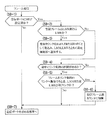
図3は、本発明の実施例1のフローチャートを示し、フレームスイッチ機構部のフレーム送信時の処理を示すフローチャートであり、フレームを受信したポートにMEP設定済みか否かを判定し(S9−1)、設定されていなければ、そのフレームを送信する宛先アドレスDAに従った送信ポートを求める処理(S9−7)へ移行する。又MEP設定済みの場合は、その受信フレームは、保守フレームのLMM又はLMRか否かを、オペレーションコードOpeCodeの“0x2b”又は“0x2a”の何れであるかによって判定し(S9−2)、LMM又はLMRの場合は、受信カウンタのカウント値をRxFCf又はRxFCbとして取込み、LMM又はLMRと共に、設定制御部13へ通知する(S9−3)。又LMMとLMRとの何れでもない場合は、伝送径路の途中にリンク集約の区間が存在するか否かを判定し(S9−5)、リンク集約の区間が存在する場合は、そのリンク集約の物理リンクへフレームを振分ける時に、LMM又はLMRと同じ物理リンクへ振分けるか否かを判定し(S9−5)、同じ物理リンクへ振分けない場合は、送信ポートを求める処理(S9−7)へ移行する。又ステップ(S9−4)に於いてリンク集約の区間がない場合、及びステップ(S9−5)に於いて同じ物理リンクへ振分ける場合、カウンタ部17によるMEPを通過した受信フレームとしてカウントアップし(S9−6)、送信ポートを求める処理(S9−7)へ移行する。
FIG. 3 shows a flowchart of the first embodiment of the present invention, which is a flowchart showing processing at the time of frame transmission by the frame switch mechanism unit, and determines whether or not MEP has been set in the port that received the frame (S9-1). If not set, the process proceeds to a process (S9-7) for obtaining a transmission port according to the destination address DA for transmitting the frame. If the MEP has already been set, whether the received frame is the LMM or LMR of the maintenance frame is determined based on whether the operation code “OpeCode” is “0x2b” or “0x2a” (S9-2). Alternatively, in the case of LMR, the count value of the reception counter is taken in as RxFCf or RxFCb and notified to the
前述のステップ(S9−5)に於けるフレームをリンク集約の物理リンクへ振分けるアルゴリズムについては示していないが、例えば、従来例に於けるMACアドレスによるアルゴリズムを適用することができる。なお、リンク集約の振分けについては、他のアルゴリズムを適用することも可能であり、本発明に於いては、リンク集約の振分け方法には依存しないので、他の振分けアルゴリズムを適用することも可能である。又前述のステップ(S9−4)による伝送途中にリンク集約の区間があるか否かの判定処理は、例えば、保守端末11から指示し、それによって、設定制御部13からテーブル格納メモリ14に設定し、フレームスイッチ機構部16は、テーブル格納メモリ14を参照して判定することも可能である。又LMM及びLMRが何れの物理リンクを経由して転送するかについて、保守者が保守端末11から予め指示しておくことも可能である。即ち、リンク集約の物理リンクに対するフレームの振分け処理は、既に知られている各種の手段を適用することが可能である。
Although the algorithm for allocating the frame to the link aggregation physical link in the above step (S9-5) is not shown, for example, the algorithm based on the MAC address in the conventional example can be applied. It should be noted that other algorithms can be applied to the link aggregation distribution, and in the present invention, other distribution algorithms can be applied because they do not depend on the link aggregation distribution method. is there. In addition, the determination process of whether or not there is a link aggregation section in the middle of transmission in the above-described step (S9-4) is instructed from the
図4は、本発明の実施例1のフローチャートであり、送信ポート決定後のフレーム送信処理のフローチャートを示し、図1のフレームスイッチ機構部16による処理に関するものであって、送信ポート決定後、その送信ポートから送信するフレームは、自装置発のLMM又はLMRかを判定し(S10−1)、自装置発のLMM又はLMRの場合は、送信カウンタのカウント値をTxFCf又はTxFCb(図2参照)として取込み、送信するフレームに書込み(S10−3)、ポートから送信する処理(S10−7)へ移行する。又ステップ(S10−1)に於いて、送信フレームは自装置発のLMM又はLMRでない場合は、送信ポートにMEP設定済みか否かを判定し(S10−2)、設定済みでない場合は、ポートから送信する処理(S10−7)へ移行する。又設定済みの場合は、フレームの伝送途中にリンク集約の区間があるか否かを判定し(S10−4)、リンク集約の区間がある場合は、フレームをリンク集約の物理リンクへ振分ける時に、そのフレームがLMM(自MEPがLMM送信側の場合)又はLMR(自MEPがLMR送信側の場合)と同じ物理リンクで伝送されるか否かを判定し(S10−5)、同じ物理リンクで伝送されない場合は、ポートから送信する処理(S10−7)へ移行する。又フレームの伝送途中にリンク集約の区間が存在しない場合、又はリンク集約の区間が存在し、且つフレームをリンク集約の物理リンクへ振分ける時に、LMM又はLMRと同じ物理リンクに振分ける場合、送信フレーム数カウンタにより加算し(S10−6)、ポートから送信する処理(S10−7)へ移行する。
4 is a flowchart of
前述のステップ(S10−4)のリンク集約の区間があるか否かの判定処理や、ステップ(S10−5)のリンク集約の物理リンクへの振分けの場合に、LMM又はLMRと同じ物理リンクか否かの判定処理は、図3のステップ(S9−4)と、ステップ(S9−5)と同様の処理で実行することができる。又フレームスイッチ機構部16(図1参照)は、送信フレームを、フレームカウンタ部17によりカウントすべきか否かを判定し、カウントアップすべき時は、前述のステップ(S9−6)及びステップ(S10−6)によりカウントアップする。保守者が保守端末11(図1参照)を操作して、LM試験の実行要求を行うと、設定制御部11のプロセッサ21によりフレームスイッチ機構部16を制御し、フレームがLMMであることを認識すると、ステップ(S10−3)に示すように、指定されたMEPに対応する送信カウンタのカウント値をLMMの中のTxFCf又はTxFCbとして設定し、ステップ(S10−7)へ移行して、MEP設定ポートから送信する。
In the above-described determination process of whether or not there is a link aggregation section in step (S10-4), and in the case of allocation to the link aggregation physical link in step (S10-5), it is the same physical link as the LMM or LMR. The determination process of whether or not can be executed by the same process as in step (S9-4) and step (S9-5) in FIG. The frame switch mechanism unit 16 (see FIG. 1) determines whether or not the transmission frame should be counted by the
フレームスイッチ機構部16(図1参照)は、前述のステップ(S9−1)及び(S9−2)により、受信ポートにMEPが設定されていて、LMRを受信した場合は、ステップ(S9−3)に従って、それに対応する受信カウンタの値を取り出す。この値が、RxFCfとなる。そして、設定制御部13へ、受信したLMRのフレームと、RxFCfをバス10経由で通知する。設定制御部13は、前回のLMR受信時に取得した情報と、今回のLMR受信で取得した情報とを基に以下の計算を行ってフレーム廃棄数を求め、このフレーム廃棄数を保守端末11へ通知する。
フレームの廃棄数(far end)=(TxFCfc−TxFCfp)−(RxFCfc−RxFCfp)
フレームの廃棄数(near end)=(TxFCbc−TxFCbp)−(RxFClc−RxFClp)
このようにして、フレームの送受信地点間に於けるフレームの廃棄数を測定することができる。
The frame switch mechanism unit 16 (see FIG. 1), when MEP is set to the reception port by the above-described steps (S9-1) and (S9-2) and the LMR is received, the step (S9-3) ) To retrieve the value of the reception counter corresponding to it. This value is RxFCf. Then, the received LMR frame and RxFCf are notified to the
Number of discarded frames (far end) = (TxFCfc−TxFCfp) − (RxFCfc−RxFCfp)
Number of discarded frames (near end) = (TxFCbc−TxFCbp) − (RxFClc−RxFClp)
In this way, it is possible to measure the number of frame discards between frame transmission / reception points.
図5は、本発明の実施例1の保守機能点設定ポート間のフレーム伝送の説明図であり、図18の従来例と同一符号は同一名称部分を示し、複数のフレーム伝送装置としてのレイヤ2スイッチ(L2SW)を介した伝送径路により、端末間でフレーム伝送し、L2SW202,L2SW203との間にリンク集約伝送径路が形成されている場合を示す。この場合、端末100からフレーム「ア−1」、「ア−2」、「ア−3」、「ア−4」を端末120宛に送信し、端末110からフレーム「イー1」を端末121宛に送信し、リンク集約伝送径路の一方の物理リンクに端末100,120間のフレームを振分け、他方の物理リンクに端末110,121間のフレームを振分け、L2SW201のポートP03にMEP−cを設定し、L2SW204のポートP31にMEP−dを設定し、ポートP03からのLMMを、リンク集約のポートP15,P25間の物理リンクに、フレーム「イ−1」と共に伝送する。従って、ポートP03から送信するフレームの中で、ポートP15,P25間のリンクに伝送するフレーム、この場合、フレーム「イー1」を送信フレームとしてカウントする。又L2SW204のポートP31に於いて受信するフレームに中で、ポートP15,P25間のリンクを介して伝送されたフレーム、この場合、フレーム「イー1」を受信フレームとしてカウントする。即ち、LMMと同一径路で伝送されるフレームを送信フレームとしてカウントし、同様にLMMと同一径路で伝送される受信フレームもカウントする。それにより、LMMと同一伝送径路のフレームの送受信数をLMMにより収集して、伝送径路の正常性を監視することができる。なお、複数のフレーム伝送装置をそれぞれ接続してフレーム伝送を行うネットワークは、既に知られている各種の構成を適用することができる。
FIG. 5 is an explanatory diagram of frame transmission between maintenance function point setting ports according to the first embodiment of the present invention. The same reference numerals as those in the conventional example of FIG. 18 denote the same name portions, and layer 2 as a plurality of frame transmission apparatuses. A case where a frame is transmitted between terminals by a transmission path via a switch (L2SW) and a link aggregation transmission path is formed between
図6は、本発明の実施例2の保守機能点設定ポート間のフレーム伝送の説明図であり、前述の図5と同一符号は同一名称部分を示し、端末100から端末120へフレーム「ア−1」、「ア−2」、「ア−3」、「ア−4」を送信し、端末110から端末121へフレーム「イ−1」を送信する場合に、L2SW202,203間にリンク集約伝送径路が形成され、L2SW201のポートP03にMEP−cを設定し、L2SW204のポートP31にMEP−dを設定し、リンク集約伝送径路の物理リンクの数に対応したLMMを形成して、MEP−c設定のL2SW201のポートP03から端末120,121への送信フレームと共に送信し、リンク集約伝送径路の各物理リンクにLMMをそれぞれ伝送し、MEP−c設定側では、物理リンク対応に送信フレーム数をカウントし、MEP−d設定側では、物理リンク対応に受信フレーム数をカウントする。この場合のリンク集約伝送径路のリンク対応の振分けは、例えば、前述のMACアドレスを基にXOR演算してリンクを求める手段を適用することができる。そして、1番目のLMMは、リンク集約の1番目の物理リンクを通るようにし、2番目のLMMは、リンク集約の2番目の物理リンクを通るようにすると、L2SW202,203間のリンク集約の1番目の物理リンクに1番目のLMMが通過し、2番目の物理リンクに2番目のLMMが通過するように制御することができる。
FIG. 6 is an explanatory diagram of frame transmission between maintenance function point setting ports according to the second embodiment of the present invention. The same reference numerals as those in FIG. 1 ”,“ A-2 ”,“ A-3 ”,“ A-4 ”are transmitted, and when the frame“ I-1 ”is transmitted from the terminal 110 to the terminal 121, the link aggregation transmission is performed between the
この場合の物理リンク対応の送信フレーム数と受信フレーム数とをそれぞれカウントするカウンタ部17(図1参照)は、例えば、図7に示すように、1〜n個の物理リンク対応の送信フレーム数をカウントする送信フレームカウンタ部17aと、受信フレーム数をカウントする受信フレームカウンタ部17bとにより構成し、フレームスイッチ機構部16(図1参照)により送受信処理するフレームがLMMか否かと、リンク集約を含む場合のフレーム通過の物理リンク識別とに従って、物理リンク対応の送信フレーム数と受信フレーム数とをそれぞれカウントすることができる。この場合、例えば、図6に於けるポートP03,P11間のLMMと他のフレームとの送信順と、ポートP26,P31間のLMMと他のフレームとの受信順序とが相違しても、物理リンク対応のLMMによって物理リンク対応にフレーム数をカウントすることができる。 In this case, the counter unit 17 (see FIG. 1) for counting the number of transmission frames corresponding to the physical link and the number of reception frames respectively (see FIG. 1), for example, the number of transmission frames corresponding to 1 to n physical links as shown in FIG. The transmission frame counter unit 17a that counts the number of received frames and the reception frame counter unit 17b that counts the number of received frames. The frame switch mechanism unit 16 (see FIG. 1) determines whether or not the frame to be transmitted / received is an LMM. The number of transmission frames and the number of reception frames corresponding to the physical link can be respectively counted according to the physical link identification of the frame passing in the case of including. In this case, for example, even if the transmission order of the LMM between the ports P03 and P11 and other frames in FIG. 6 and the reception order of the LMM between the ports P26 and P31 and the other frames differ, The number of frames corresponding to the physical link can be counted by the LMM corresponding to the link.
図8は、本発明の実施例2のフローチャートを示し、送信ポートを決定する送信フレーム決定後の送信フレームの処理に於いて、先ず、送信ポートに、MEP設定済みか否かを判定する(S15−1)。送信ポートにMEPが設定されていない場合は、送信処理に移行する。又MEPが設定されている場合、送信フレームは、設定制御部13(図1参照)からのLMMか否かを判定する(S15−2)。LMMの場合はステップ(S15−3)へ移行し、LMMでない場合は、ステップ(S15−5)へ移行する。LMMの場合の処理を行うステップ(S15−3)に於いては、LMMを転送する途中にリンク集約の区間が存在するか否かを判定する処理を行うもので、リンク集約の区間がない場合は、送信処理に移行し、又リンク集約がある場合、例えば、2個の物理リンクの場合、第1のLMMをリンク集約の1番目の物理リンクを通るフレームとして作成し、その物理リンクに対応する送信カウンタとしてTxFCf(図2参照)をLMMに書込み、又第2のLMMをリンク集約の2番目の物理リンクを通るフレームとして作成し、その物理リンクに対応する送信カウンタとして、TxFCfをLMMに書込み(S15−4)、そして、送信処理に移行する。 FIG. 8 shows a flowchart of the second embodiment of the present invention. In the processing of the transmission frame after determining the transmission frame for determining the transmission port, first, it is determined whether or not MEP has been set in the transmission port (S15). -1). If no MEP is set for the transmission port, the process proceeds to transmission processing. If MEP is set, it is determined whether the transmission frame is an LMM from the setting control unit 13 (see FIG. 1) (S15-2). If it is LMM, the process proceeds to step (S15-3). If it is not LMM, the process proceeds to step (S15-5). In the step (S15-3) for performing the process in the case of LMM, it is determined whether or not there is a link aggregation section in the middle of transferring the LMM, and there is no link aggregation section Shifts to transmission processing, and when there is link aggregation, for example, in the case of two physical links, the first LMM is created as a frame that passes through the first physical link of link aggregation and corresponds to the physical link. TxFCf (see FIG. 2) is written to the LMM as a transmission counter to be used, and a second LMM is created as a frame passing through the second physical link of the link aggregation, and TxFCf is stored in the LMM as a transmission counter corresponding to the physical link. Writing (S15-4) and the process proceeds to transmission processing.
又ステップ(S15−2)に於いて、送信フレームがLMMでない場合、途中にリンク集約の区間があるか否かを判定し(S15−5)、リンク集約がない場合、送信フレーム数カウンタに加算し(S15−8)、送信処理に移行する。又ステップ(S15−5)に於いて、リンク集約の区間ありの判定の場合、フレームをリンク集約の物理リンクへ振分ける時に、振分け先物理リンクを求め(S15−6)、その振分け先物理リンクに対応する送信フレーム数カウンタに加算し(S15−7)、送信処理へ移行する。 In step (S15-2), if the transmission frame is not an LMM, it is determined whether there is a link aggregation section in the middle (S15-5). If there is no link aggregation, it is added to the transmission frame number counter. (S15-8), and the process proceeds to transmission processing. If it is determined in step (S15-5) that there is a link aggregation section, the distribution destination physical link is obtained (S15-6) when the frame is allocated to the link aggregation physical link. (S15-7), and the process proceeds to the transmission process.
図9は、本発明の実施例2のフローチャートを示し、LMMを受信する側のフレーム伝送装置としてのL2SWに於けるフレーム受信処理として、その受信フレームはLMMか否かを判定し(S16−1)、LMMの場合は、ステップ(S16−2)に移行し、LMMでない場合は、ステップ(S16−7)に移行する。ステップ(S16−2)では、受信ポートにMEP設定済みか否かを判定し、MEPが設定されていない場合は、送信ポートを求める処理に移行する。又MEPが設定されている場合は、フレームの伝送径路にリンク集約の区間があるか否かを判定し(S16−3)、リンク集約の区間がある場合は、LMMをリンク集約の物理リンクへ振分ける振分け先の物理リンクを求め、その物理リンク対応の受信カウンタのカウント値をRxFCfとして取込む(S16−4)。又リンク集約の区間がない場合は、受信カウンタのカウント値をRxFCfとして取込む(S16−6)。そして、ステップ(S16−4)又はステップ(S16−6)の後に、取込んだRxFCfとLMMとを設定制御部13(図1参照)へ通知し(S16−5)、送信ポートを求める処理へ移行する。 FIG. 9 shows a flowchart of the second embodiment of the present invention. As a frame reception process in the L2SW as the frame transmission apparatus on the LMM receiving side, it is determined whether or not the received frame is an LMM (S16-1). In the case of LMM, the process proceeds to step (S16-2), and in the case of not LMM, the process proceeds to step (S16-7). In step (S16-2), it is determined whether or not MEP has been set for the reception port. If MEP has not been set, the process proceeds to processing for obtaining a transmission port. If MEP is set, it is determined whether or not there is a link aggregation section in the frame transmission path (S16-3). If there is a link aggregation section, the LMM is changed to a link aggregation physical link. The distribution destination physical link is obtained, and the count value of the reception counter corresponding to the physical link is taken in as RxFCf (S16-4). If there is no link aggregation section, the count value of the reception counter is fetched as RxFCf (S16-6). Then, after step (S16-4) or step (S16-6), the captured RxFCf and LMM are notified to the setting control unit 13 (see FIG. 1) (S16-5), and the process for obtaining the transmission port is performed. Transition.
又MEP設定済みか否かの判定ステップ(S16−7)に於いて、MEP設定済みでないと判定した場合、送信ポートを求める処理へ移行する。又MEP設定済みの判定の場合は、フレーム伝送径路にリンク集約の区間があるか否かを判定し(S16−8)、ない場合は、受信フレーム数カウンタに加算して(S16−11)、送信ポートを求める処理へ移行する。又リンク集約の区間がある場合は、フレームをリンク集約の物理リンクへ振分ける時の振分け先物理リンクを求め(S16−9)、その振分け先物理リンクに対応する受信フレーム数カウンタに加算して(S16−10)、送信ポートを求める処理へ移行する。従って、LMMが通過するリンク集約の物理リンクに振分けられたフレームを、その物理リンク対応にカウントすることができる。 If it is determined that the MEP has not been set in the step of determining whether or not the MEP has been set (S16-7), the process proceeds to a process for obtaining a transmission port. If it is determined that the MEP has been set, it is determined whether or not there is a link aggregation section in the frame transmission path (S16-8). If not, the frame is added to the received frame number counter (S16-11). The process proceeds to processing for obtaining a transmission port. If there is a link aggregation section, the distribution destination physical link when distributing the frame to the link aggregation physical link is obtained (S16-9), and added to the received frame number counter corresponding to the distribution destination physical link. (S16-10), the process proceeds to a process for obtaining a transmission port. Therefore, the frames allocated to the link aggregation physical link through which the LMM passes can be counted as corresponding to the physical link.
図10は、本発明の実施例3の保守機能点設定ポート間のフレーム伝送の説明図であり、前述の図5及び図6と同一符号は同一名称部分を示し、MEP−cをL2SW202のポートP11に設定した場合を示す。この場合、前述の図6に於いては、L2SW201のフレーム送信ポートに相当するポートP03にMEP−cを設定しているが、図10に示す実施例3に於いては、そのMEP−cをL2SW202の受信ポートに相当するポートP11に設定した場合を示す。このL2SW202は、L2SW201から受信したフレームに対して、矢印で示すLMM挿入位置に挿入する。なお、L2SW202,203間にリンク集約の伝送径路が形成されているから、リンク対応のLMMを生成する。それによって、ポートP15,P25間は、フレーム「イ−1」の後にLMMが転送され、ポートP14,P24間は、フレーム「ア−1」の後にLMMが転送される場合を示している。又この場合、ポートP26,P31間に於いては、ポートP26からのフレーム送信処理に対応して、フレーム「ア−1」の後にLMMが転送され、フレーム「イ−1」,「ア−4」の後にLMMが転送される場合を示している。MEP−c設定のポートP11に於いては、リンク集約の物理リンク対応のLMM間のフレーム数をカウントする。従って、MEP−cを設定したポートP11に於いて、リンク振分けに対応した送信フレームをカウントし、MEP−d設定のポートP31に於いて、リンク振分けに対応した受信フレームをカウントすることにより、ポートP11,P31間のフレームロスの有無を監視することができる。
FIG. 10 is an explanatory diagram of frame transmission between maintenance function point setting ports according to the third embodiment of the present invention. The same reference numerals as those in FIGS. 5 and 6 indicate the same name parts, and MEP-c is the port of the
図11は、本発明の実施例3のフローチャートであり、フレームの受信ポートにMEP設定済みか否かを判定し(S17−1)、設定されていない場合は、送信ポートを求める処理へ移行し、設定されている場合は、受信フレームは設定制御部13(図1参照)からのLMMか否かを判定し(S17−2)、LMMの場合はステップ(S17−3)へ移行し、LMMでない場合はステップ(S17−5)へ移行する。ステップ(S17−3)に於いては、LMMを転送する途中にリンク集約の区間があるか否かを判定し、リンク集約の区間が存在しない場合は、送信ポートを求める処理へ移行し、リンク集約の区間が存在する場合は、LMMをリンク集約の1番目の物理リンクを通るフレームとして作成し、該当物理リンクに対応する受信カウンタを取込み、TxFCfとしてLMMに書込み、又LMMをリンク集約の2番目の物理リンクを通るフレームとして作成し、該当リンクに対応する受信カウンタを取込み、TxFCfとしてLMMに書込む。なお、3番目、4番目の物理リンクが存在する場合は、それぞれの物理リンクに対応して前述の処理を行うことになり、処理終了により、送信ポートを求める処理へ移行する。又ステップ(S17−5)に於いては、途中にリンク集約の区間があるか否かを判定し、リンク集約の区間がある場合は、フレームをリンク集約の物理リンクへ振分けるときの振分け先物理リンクを求め(S17−6)、その振分け先物理リンクに対応する受信フレーム数カウンタに加算し(S17−7)、送信ポートを求める処理へ移行する。又途中にリンク集約の区間がない場合は、受信フレーム数カウンタに加算して(S17−8)、送信ポートを求める処理へ移行する。 FIG. 11 is a flowchart according to the third embodiment of the present invention. It is determined whether or not MEP has been set for the reception port of the frame (S17-1). If not, the process proceeds to processing for obtaining the transmission port. If it is set, it is determined whether or not the received frame is an LMM from the setting control unit 13 (see FIG. 1) (S17-2). If it is LMM, the process proceeds to step (S17-3). If not, the process proceeds to step (S17-5). In step (S17-3), it is determined whether or not there is a link aggregation section in the middle of transferring the LMM. If there is no link aggregation section, the process proceeds to processing for obtaining a transmission port, and the link When there is an aggregation section, an LMM is created as a frame passing through the first physical link of link aggregation, a reception counter corresponding to the physical link is taken in, written into the LMM as TxFCf, and the LMM is 2 of link aggregation The frame is created as a frame passing through the second physical link, the reception counter corresponding to the link is fetched, and written in the LMM as TxFCf. If the third and fourth physical links exist, the above-described processing is performed corresponding to each physical link, and the processing shifts to processing for obtaining a transmission port when the processing ends. In step (S17-5), it is determined whether or not there is a link aggregation section in the middle. If there is a link aggregation section, the distribution destination for distributing the frame to the link aggregation physical link is determined. The physical link is obtained (S17-6), added to the received frame number counter corresponding to the distribution destination physical link (S17-7), and the process proceeds to the process for obtaining the transmission port. If there is no link aggregation section on the way, it is added to the received frame number counter (S17-8), and the process proceeds to a process for obtaining a transmission port.
図12は、本発明の実施例3のフローチャートであり、送信ポートを決定した後のフレーム送信処理を示し、送信フレームはLMR(Loss Measurement Reply)か否かを判定し(S18−1)、LMRの場合は、ステップ(S18−2)へ移行し、又LMRでなかった場合は、ステップ(S18−7)へ移行する。LMRの場合は、送信ポートにMEP設定済みか否かを判定し(S18−2)、MEPが設定されていない場合は、ポートからフレームを送信する処理へ移行する。又MEPが設定されている場合は、そのフレームが伝送された径路にリンク集約の区間が存在したか否かを判定し(S18−3)、リンク集約の区間が存在しない場合は、送信カウンタをFxFClとして取込み(S18−6)、次のステップ(S18−5)へ移行する。又リンク集約の区間が存在する場合は、LMRフレームをリンク集約の物理リンクへ振分けるときの振分け先物理リンクを求め、その物理リンク対応の送信カウンタをRxFClとして取込み(S18−4)、取込んだRxFClとLMRとを設定制御部13(図1参照)へ通知し(S18−5)、ポートから送信する処理を行う。又送信フレームがLMRでない時のステップ(S18−7)に於いては、フレームの伝送径路にリンク集約の区間が存在したか否かを判定し、リンク集約の区間が存在しない場合は、送信フレーム数カウンタに加算し(S18−8)、ポートから送信する処理へ移行する。又リンク集約の区間が存在する場合は、リンク集約区間の複数の物理リンクの何れの物理リンクへ振分けるか、その振分け先物理リンクを求め(S18−9)、その振分け先物理リンクに対応する送信フレーム数カウンタに加算して(S18−10)、ポートから送信する処理を行う。前述の処理により、フレームを送信するポートによる保守フレームLMRを受信して、廃棄フレーム数の測定を行うことができる。 FIG. 12 is a flowchart of the third embodiment of the present invention, showing a frame transmission process after determining a transmission port. It is determined whether or not the transmission frame is LMR (Loss Measurement Reply) (S18-1). In the case of (1), the process proceeds to step (S18-2), and if it is not LMR, the process proceeds to step (S18-7). In the case of LMR, it is determined whether or not MEP has been set for the transmission port (S18-2). If MEP has not been set, the process proceeds to processing for transmitting a frame from the port. If the MEP is set, it is determined whether or not there is a link aggregation section in the path through which the frame is transmitted (S18-3). If there is no link aggregation section, the transmission counter is set. FxFC1 is taken in (S18-6), and the process proceeds to the next step (S18-5). If there is a link aggregation section, a distribution-destination physical link for allocating an LMR frame to a link aggregation physical link is obtained, and a transmission counter corresponding to the physical link is acquired as RxFC1 (S18-4). The RxFCl and LMR are notified to the setting control unit 13 (see FIG. 1) (S18-5), and the process of transmitting from the port is performed. In step S18-7 when the transmission frame is not LMR, it is determined whether or not there is a link aggregation section in the transmission path of the frame. If there is no link aggregation section, the transmission frame The number is added to the number counter (S18-8), and the process proceeds to transmission from the port. If there is a link aggregation section, which physical link of the plurality of physical links in the link aggregation section is to be allocated, or the distribution destination physical link is obtained (S18-9), and the distribution destination physical link is supported. The transmission frame number counter is added (S18-10), and processing for transmitting from the port is performed. Through the above-described processing, the maintenance frame LMR by the port that transmits the frame can be received, and the number of discarded frames can be measured.
10 バス
11 保守端末
12 通信ポート群
13 設定制御部
14 テーブル格納メモリ
15 学習テーブル
16 フレームスイッチ機構部
17 カウンタ部
21 プロセッサ(CPU)
22 メモリ
23 通信インタフェース部(通信IF)
DESCRIPTION OF SYMBOLS 10
22 Memory 23 Communication interface (communication IF)
Claims (4)
端末又は他のフレーム伝送装置との間を接続する為の複数のポートと、
該複数のポートの中の保守機能点設定ポートと他のフレーム伝送装置の保守機能点設定ポートとの間で送受信する保守フレームが通過するリンク集約の物理リンクと同一の物理リンクを通過する送受信フレームを識別し、該識別した送受信フレームをカウントするフレームカウンタ部と、該フレームカウンタ部により前記保守フレーム送出直前までの前記送受信フレームのカウント値を前記保守フレームにより前記保守機能点設定ポート間で相互に通知する制御処理を行う構成とを備えたフレームスイッチ機構部と、
装置内各部を制御すると共に、前記フレームスイッチ機構部からの前記保守フレームにより通知された送信フレーム数と前記フレームカウンタ部による受信フレーム数とを基にフレーム廃棄数を求める制御処理を実行する設定制御部と
を含む構成を有することを特徴とするフレーム伝送装置。 In a frame transmission apparatus that performs frame transmission via a network,
A plurality of ports for connecting terminals or other frame transmission devices;
A transmission / reception frame that passes through the same physical link as a link aggregation physical link through which a maintenance frame transmitted / received between the maintenance function point setting port of the plurality of ports and a maintenance function point setting port of another frame transmission apparatus passes A frame counter unit that counts the identified transmission / reception frames , and a count value of the transmission / reception frames until immediately before the maintenance frame is sent by the frame counter unit between the maintenance function point setting ports by the maintenance frame. A frame switch mechanism having a configuration for performing control processing to be notified;
Setting control for controlling each part in the apparatus and executing control processing for obtaining the number of discarded frames based on the number of transmitted frames notified by the maintenance frame from the frame switch mechanism and the number of received frames by the frame counter A frame transmission apparatus comprising:
前記フレーム伝送装置の複数のポートの中の保守機能点設定ポートと他のフレーム伝送装置の複数のポートの中の保守機能点設定ポートとの間に、リンク集約の物理リンクを経由して伝送する保守フレームと同一の物理リンクを経由する送受信フレームを識別してフレームカウンタ部によりカウントし、該フレームカウンタ部による前記保守フレーム送出直前までのカウント値を前記保守フレームにより前記保守機能点設定ポート間で通知し、前記保守フレームが通過する前記リンク集約の物理リンク対応の受信フレーム数と前記保守フレームにより通知された送信フレーム数とにより、フレーム廃棄数を求める処理過程を含む
ことを特徴とするフレーム廃棄数測定方法。 In a frame discard number measuring method of performing frame transmission between frame transmission apparatuses via a network and measuring the number of frame discards in the transmission process of the frame,
Transmission is performed via a link aggregation physical link between a maintenance function point setting port among a plurality of ports of the frame transmission apparatus and a maintenance function point setting port among a plurality of ports of another frame transmission apparatus. A transmission / reception frame that passes through the same physical link as the maintenance frame is identified and counted by the frame counter unit, and the count value immediately before the maintenance frame is sent by the frame counter unit between the maintenance function point setting ports by the maintenance frame. A frame discarding process including a process of determining the number of discarded frames based on the number of received frames corresponding to the physical link of the link aggregation through which the maintenance frame passes and the number of transmission frames notified by the maintenance frame Number measurement method.
Priority Applications (1)
| Application Number | Priority Date | Filing Date | Title |
|---|---|---|---|
| JP2009138091A JP5032533B2 (en) | 2009-06-09 | 2009-06-09 | Frame transmission apparatus and frame discard number measuring method |
Applications Claiming Priority (1)
| Application Number | Priority Date | Filing Date | Title |
|---|---|---|---|
| JP2009138091A JP5032533B2 (en) | 2009-06-09 | 2009-06-09 | Frame transmission apparatus and frame discard number measuring method |
Publications (2)
| Publication Number | Publication Date |
|---|---|
| JP2010287939A JP2010287939A (en) | 2010-12-24 |
| JP5032533B2 true JP5032533B2 (en) | 2012-09-26 |
Family
ID=43543351
Family Applications (1)
| Application Number | Title | Priority Date | Filing Date |
|---|---|---|---|
| JP2009138091A Expired - Fee Related JP5032533B2 (en) | 2009-06-09 | 2009-06-09 | Frame transmission apparatus and frame discard number measuring method |
Country Status (1)
| Country | Link |
|---|---|
| JP (1) | JP5032533B2 (en) |
Cited By (5)
| Publication number | Priority date | Publication date | Assignee | Title |
|---|---|---|---|---|
| US10751267B2 (en) | 2016-12-21 | 2020-08-25 | Conopco, Inc. | Personal care compositions comprising poorly soluble compounds |
| US11077039B2 (en) | 2016-12-21 | 2021-08-03 | Conopco, Inc. | Topical skin lightening additive and composition with amino acids and nicotinamide compounds |
| US11260005B2 (en) | 2016-12-21 | 2022-03-01 | Conopco, Inc. | Personal care compositions with glutathione precursor comprising 4-substituted resorcinols and amino acids |
| US11337908B2 (en) | 2016-12-21 | 2022-05-24 | Conopco, Inc. | Personal care compositions with cystine |
| US11540984B2 (en) | 2018-05-23 | 2023-01-03 | Conopco, Inc. | Nanoemulsions and a method for making the same |
Families Citing this family (2)
| Publication number | Priority date | Publication date | Assignee | Title |
|---|---|---|---|---|
| JP5747732B2 (en) * | 2011-08-16 | 2015-07-15 | 日本電気株式会社 | COMMUNICATION SYSTEM, COMMUNICATION CONTROL METHOD, COMMUNICATION DEVICE, COMMUNICATION DEVICE CONTROL METHOD, AND COMMUNICATION DEVICE CONTROL PROGRAM |
| US9369359B2 (en) | 2011-09-20 | 2016-06-14 | Nec Corporation | Diagnostic system |
Family Cites Families (3)
| Publication number | Priority date | Publication date | Assignee | Title |
|---|---|---|---|---|
| JP4454516B2 (en) * | 2005-02-16 | 2010-04-21 | 富士通株式会社 | Fault detection device |
| JP2008244870A (en) * | 2007-03-27 | 2008-10-09 | Sumitomo Electric Ind Ltd | COMMUNICATION SYSTEM, RELAY DEVICE USED FOR THE SAME, AND METHOD OF MEASURING FRAME LOSS |
| JP5056775B2 (en) * | 2009-03-05 | 2012-10-24 | 日立電線株式会社 | Frame loss measurement method and measurement system, and network relay device |
-
2009
- 2009-06-09 JP JP2009138091A patent/JP5032533B2/en not_active Expired - Fee Related
Cited By (9)
| Publication number | Priority date | Publication date | Assignee | Title |
|---|---|---|---|---|
| US10751267B2 (en) | 2016-12-21 | 2020-08-25 | Conopco, Inc. | Personal care compositions comprising poorly soluble compounds |
| US10980718B2 (en) | 2016-12-21 | 2021-04-20 | Conopco, Inc. | Personal care compositions comprising poorly soluble compounds |
| US11077039B2 (en) | 2016-12-21 | 2021-08-03 | Conopco, Inc. | Topical skin lightening additive and composition with amino acids and nicotinamide compounds |
| US11260005B2 (en) | 2016-12-21 | 2022-03-01 | Conopco, Inc. | Personal care compositions with glutathione precursor comprising 4-substituted resorcinols and amino acids |
| US11337908B2 (en) | 2016-12-21 | 2022-05-24 | Conopco, Inc. | Personal care compositions with cystine |
| US11596586B2 (en) | 2016-12-21 | 2023-03-07 | Conopco, Inc. | Personal care compositions with glutathione precursor comprising 4-substituted resorcinols and amino acids |
| US11666519B2 (en) | 2016-12-21 | 2023-06-06 | Conopco, Inc. | Personal care compositions with cystine |
| US11759412B2 (en) | 2016-12-21 | 2023-09-19 | Conopco, Inc. | Personal care compositions with glutathione precursor comprising 4-substituted resorcinols and amino acids |
| US11540984B2 (en) | 2018-05-23 | 2023-01-03 | Conopco, Inc. | Nanoemulsions and a method for making the same |
Also Published As
| Publication number | Publication date |
|---|---|
| JP2010287939A (en) | 2010-12-24 |
Similar Documents
| Publication | Publication Date | Title |
|---|---|---|
| JP5032533B2 (en) | Frame transmission apparatus and frame discard number measuring method | |
| US10819605B2 (en) | Method, apparatus, and system for implementing delay measurement | |
| US11621906B2 (en) | Method for test traffic generation and inspection, and associated switch input or output port and switch | |
| US8885488B2 (en) | Reachability detection in trill networks | |
| CN106612211A (en) | A rout detecting method, a controller and a network device in a VxLAN | |
| CN103416022B (en) | In-Service Throughput Testing Method and System in Distributed Router/Switch Architecture | |
| EP2760182A1 (en) | Data communication apparatus, data transmission method, and computer system | |
| JP2015057931A (en) | Network apparatus, communication system, and detection method and program for abnormal traffic | |
| CN110943879B (en) | Network performance monitoring using proactive measurement protocol and relay mechanisms | |
| EP3188413B1 (en) | Method, apparatus, and system for implementing packet loss detection | |
| CN106375158A (en) | Packet loss detection method, network device and system | |
| CN106034045A (en) | Ethernet link failure positioning method, device and system | |
| CN111756588B (en) | Communication link detection method and related device | |
| CN104604185A (en) | Connectivity checking of a bidirectional circular path in a communication network | |
| JP5938995B2 (en) | Communication device | |
| CN118075195A (en) | Data center network failure rerouting method, device, electronic device and medium | |
| JP5440200B2 (en) | Relay device and bandwidth control method | |
| CN112073270B (en) | Link fault detection method and device | |
| US8593997B2 (en) | Full duplex/half duplex mismatch detecting method and full duplex/half duplex mismatch detecting apparatus applicable with the method | |
| CN110557302B (en) | Network device packet observation data collection method | |
| KR20190001402A (en) | SDN controller and method for generating of failover group using the same and method for failover in SDN | |
| CN101262421A (en) | Relay device and relay method | |
| US20070115838A1 (en) | Method and system for loop-back and continue in packet-based network | |
| CN110572332B (en) | Network equipment message observation data acquisition task dividing method | |
| KR101144165B1 (en) | System for measuring performance of network equipment based on ethernet |
Legal Events
| Date | Code | Title | Description |
|---|---|---|---|
| A621 | Written request for application examination |
Free format text: JAPANESE INTERMEDIATE CODE: A621 Effective date: 20110310 |
|
| RD03 | Notification of appointment of power of attorney |
Free format text: JAPANESE INTERMEDIATE CODE: A7423 Effective date: 20110915 |
|
| A977 | Report on retrieval |
Free format text: JAPANESE INTERMEDIATE CODE: A971007 Effective date: 20120305 |
|
| A131 | Notification of reasons for refusal |
Free format text: JAPANESE INTERMEDIATE CODE: A131 Effective date: 20120417 |
|
| A521 | Written amendment |
Free format text: JAPANESE INTERMEDIATE CODE: A523 Effective date: 20120601 |
|
| TRDD | Decision of grant or rejection written | ||
| A01 | Written decision to grant a patent or to grant a registration (utility model) |
Free format text: JAPANESE INTERMEDIATE CODE: A01 Effective date: 20120619 |
|
| A01 | Written decision to grant a patent or to grant a registration (utility model) |
Free format text: JAPANESE INTERMEDIATE CODE: A01 |
|
| A61 | First payment of annual fees (during grant procedure) |
Free format text: JAPANESE INTERMEDIATE CODE: A61 Effective date: 20120628 |
|
| R150 | Certificate of patent or registration of utility model |
Free format text: JAPANESE INTERMEDIATE CODE: R150 |
|
| FPAY | Renewal fee payment (event date is renewal date of database) |
Free format text: PAYMENT UNTIL: 20150706 Year of fee payment: 3 |
|
| R250 | Receipt of annual fees |
Free format text: JAPANESE INTERMEDIATE CODE: R250 |
|
| LAPS | Cancellation because of no payment of annual fees |