JP4969060B2 - Automatic analyzer - Google Patents
Automatic analyzer Download PDFInfo
- Publication number
- JP4969060B2 JP4969060B2 JP2005167632A JP2005167632A JP4969060B2 JP 4969060 B2 JP4969060 B2 JP 4969060B2 JP 2005167632 A JP2005167632 A JP 2005167632A JP 2005167632 A JP2005167632 A JP 2005167632A JP 4969060 B2 JP4969060 B2 JP 4969060B2
- Authority
- JP
- Japan
- Prior art keywords
- sample
- reagent
- liquid
- automatic analyzer
- transport path
- Prior art date
- Legal status (The legal status is an assumption and is not a legal conclusion. Google has not performed a legal analysis and makes no representation as to the accuracy of the status listed.)
- Expired - Fee Related
Links
Images


Classifications
-
- G—PHYSICS
- G01—MEASURING; TESTING
- G01N—INVESTIGATING OR ANALYSING MATERIALS BY DETERMINING THEIR CHEMICAL OR PHYSICAL PROPERTIES
- G01N35/00—Automatic analysis not limited to methods or materials provided for in any single one of groups G01N1/00 - G01N33/00; Handling materials therefor
- G01N35/08—Automatic analysis not limited to methods or materials provided for in any single one of groups G01N1/00 - G01N33/00; Handling materials therefor using a stream of discrete samples flowing along a tube system, e.g. flow injection analysis
-
- B—PERFORMING OPERATIONS; TRANSPORTING
- B01—PHYSICAL OR CHEMICAL PROCESSES OR APPARATUS IN GENERAL
- B01F—MIXING, e.g. DISSOLVING, EMULSIFYING OR DISPERSING
- B01F33/00—Other mixers; Mixing plants; Combinations of mixers
- B01F33/30—Micromixers
- B01F33/302—Micromixers the materials to be mixed flowing in the form of droplets
- B01F33/3021—Micromixers the materials to be mixed flowing in the form of droplets the components to be mixed being combined in a single independent droplet, e.g. these droplets being divided by a non-miscible fluid or consisting of independent droplets
-
- B—PERFORMING OPERATIONS; TRANSPORTING
- B01—PHYSICAL OR CHEMICAL PROCESSES OR APPARATUS IN GENERAL
- B01F—MIXING, e.g. DISSOLVING, EMULSIFYING OR DISPERSING
- B01F33/00—Other mixers; Mixing plants; Combinations of mixers
- B01F33/30—Micromixers
- B01F33/3031—Micromixers using electro-hydrodynamic [EHD] or electro-kinetic [EKI] phenomena to mix or move the fluids
-
- B—PERFORMING OPERATIONS; TRANSPORTING
- B01—PHYSICAL OR CHEMICAL PROCESSES OR APPARATUS IN GENERAL
- B01L—CHEMICAL OR PHYSICAL LABORATORY APPARATUS FOR GENERAL USE
- B01L2200/00—Solutions for specific problems relating to chemical or physical laboratory apparatus
- B01L2200/02—Adapting objects or devices to another
- B01L2200/026—Fluid interfacing between devices or objects, e.g. connectors, inlet details
- B01L2200/027—Fluid interfacing between devices or objects, e.g. connectors, inlet details for microfluidic devices
-
- B—PERFORMING OPERATIONS; TRANSPORTING
- B01—PHYSICAL OR CHEMICAL PROCESSES OR APPARATUS IN GENERAL
- B01L—CHEMICAL OR PHYSICAL LABORATORY APPARATUS FOR GENERAL USE
- B01L2300/00—Additional constructional details
- B01L2300/08—Geometry, shape and general structure
- B01L2300/0803—Disc shape
-
- B—PERFORMING OPERATIONS; TRANSPORTING
- B01—PHYSICAL OR CHEMICAL PROCESSES OR APPARATUS IN GENERAL
- B01L—CHEMICAL OR PHYSICAL LABORATORY APPARATUS FOR GENERAL USE
- B01L2300/00—Additional constructional details
- B01L2300/08—Geometry, shape and general structure
- B01L2300/0809—Geometry, shape and general structure rectangular shaped
- B01L2300/0816—Cards, e.g. flat sample carriers usually with flow in two horizontal directions
-
- B—PERFORMING OPERATIONS; TRANSPORTING
- B01—PHYSICAL OR CHEMICAL PROCESSES OR APPARATUS IN GENERAL
- B01L—CHEMICAL OR PHYSICAL LABORATORY APPARATUS FOR GENERAL USE
- B01L2300/00—Additional constructional details
- B01L2300/08—Geometry, shape and general structure
- B01L2300/0861—Configuration of multiple channels and/or chambers in a single devices
- B01L2300/0864—Configuration of multiple channels and/or chambers in a single devices comprising only one inlet and multiple receiving wells, e.g. for separation, splitting
-
- B—PERFORMING OPERATIONS; TRANSPORTING
- B01—PHYSICAL OR CHEMICAL PROCESSES OR APPARATUS IN GENERAL
- B01L—CHEMICAL OR PHYSICAL LABORATORY APPARATUS FOR GENERAL USE
- B01L2300/00—Additional constructional details
- B01L2300/08—Geometry, shape and general structure
- B01L2300/0861—Configuration of multiple channels and/or chambers in a single devices
- B01L2300/0867—Multiple inlets and one sample wells, e.g. mixing, dilution
-
- B—PERFORMING OPERATIONS; TRANSPORTING
- B01—PHYSICAL OR CHEMICAL PROCESSES OR APPARATUS IN GENERAL
- B01L—CHEMICAL OR PHYSICAL LABORATORY APPARATUS FOR GENERAL USE
- B01L2300/00—Additional constructional details
- B01L2300/08—Geometry, shape and general structure
- B01L2300/089—Virtual walls for guiding liquids
-
- B—PERFORMING OPERATIONS; TRANSPORTING
- B01—PHYSICAL OR CHEMICAL PROCESSES OR APPARATUS IN GENERAL
- B01L—CHEMICAL OR PHYSICAL LABORATORY APPARATUS FOR GENERAL USE
- B01L2400/00—Moving or stopping fluids
- B01L2400/04—Moving fluids with specific forces or mechanical means
- B01L2400/0403—Moving fluids with specific forces or mechanical means specific forces
- B01L2400/0415—Moving fluids with specific forces or mechanical means specific forces electrical forces, e.g. electrokinetic
- B01L2400/0427—Electrowetting
-
- G—PHYSICS
- G01—MEASURING; TESTING
- G01N—INVESTIGATING OR ANALYSING MATERIALS BY DETERMINING THEIR CHEMICAL OR PHYSICAL PROPERTIES
- G01N35/00—Automatic analysis not limited to methods or materials provided for in any single one of groups G01N1/00 - G01N33/00; Handling materials therefor
- G01N35/10—Devices for transferring samples or any liquids to, in, or from, the analysis apparatus, e.g. suction devices, injection devices
- G01N2035/1027—General features of the devices
- G01N2035/1034—Transferring microquantities of liquid
Landscapes
- Chemical & Material Sciences (AREA)
- Chemical Kinetics & Catalysis (AREA)
- Physics & Mathematics (AREA)
- Analytical Chemistry (AREA)
- Health & Medical Sciences (AREA)
- Life Sciences & Earth Sciences (AREA)
- Fluid Mechanics (AREA)
- Biochemistry (AREA)
- General Health & Medical Sciences (AREA)
- General Physics & Mathematics (AREA)
- Immunology (AREA)
- Pathology (AREA)
- Automatic Analysis And Handling Materials Therefor (AREA)
Description
本発明は血液,尿等の生体成分の定性・定量分析を実行する自動分析装置に係り、特に小型で、より多くの試薬を搭載でき、かつ時間あたりの処理能力の高い自動分析装置に関する。 The present invention relates to an automatic analyzer that performs qualitative / quantitative analysis of biological components such as blood and urine, and more particularly to an automatic analyzer that is small in size, can be loaded with more reagents, and has a high throughput per hour.
血液等の生体試料を自動的に分析し、結果を出力する自動分析装置は、患者数の多い大病院,中小病院,医院から検査を請け負い検査を行う検査センターなどにおいて効率良く分析を行うのになくてはならない装置になっている。 Automatic analyzers that automatically analyze biological samples such as blood and output the results can be used for efficient analysis at large hospitals, small and medium hospitals, and clinics with large numbers of patients. It is an indispensable device.
そのような自動分析装置は、コンパクトでより多種類の分析ができ、かつ処理速度の高いものが望まれており、従来種々のものが提案されている。例えば特許文献1には複数の反応セルを円周上に配置し、回転可能な反応ディスクを用い、個々の反応セルに検体,試薬をプローブで分注し、混合液の吸光度の変化を光度計で検出して検体の特定成分の濃度を分析する装置が開示されている。 Such an automatic analyzer is desired to be compact and capable of more types of analysis and to have a high processing speed, and various types of automatic analyzers have been proposed. For example, in Patent Document 1, a plurality of reaction cells are arranged on the circumference, a rotatable reaction disk is used, a sample and a reagent are dispensed to each reaction cell with a probe, and a change in absorbance of the mixed solution is measured with a photometer. Discloses an apparatus for analyzing the concentration of a specific component of a specimen.
この方法では、全ての反応セルが反応ディスクの回転により光度計を通過して測光されるので、必要な光度計は1つのみであり、全てのセルに対して同一の条件でばらつきの小さい分析が可能である。また、検体,試薬の分注はどの反応セルに対しても可能なので、必要な分析が自由な順番で実施することができ、処理能力の高い分析が可能である。 In this method, all the reaction cells are measured by passing through the photometer by the rotation of the reaction disk, so only one photometer is required, and all cells are analyzed under the same conditions and with little variation. Is possible. In addition, since sample and reagent can be dispensed to any reaction cell, necessary analysis can be performed in any order, and analysis with high throughput is possible.
しかし、この方法では、反応セルに光度計の光束径以上の反応液(検体+試薬)が入っている必要があり、一定量以上の検体/試薬が必要である。また、処理速度を大きくするためには反応セルの数を多くする必要があるが、一方で反応セルには一定容積が必要であり、必然的に装置が大型化してしまうという問題があった。 However, in this method, the reaction cell needs to contain a reaction solution (specimen + reagent) that is larger than the luminous flux diameter of the photometer, and a certain amount of specimen / reagent is required. Further, in order to increase the processing speed, it is necessary to increase the number of reaction cells. On the other hand, there is a problem that the reaction cell needs a certain volume, and the apparatus is inevitably enlarged.
これに対して非特許文献1には、エレクトロウェッチングと称する電極列の配置された平板間に液滴を操作する技術を応用して、検体と試薬を反応させLEDを用いた光学系で反応液滴の吸光度を検出して4種類の項目の濃度を分析した例が紹介されている。エレクトロウェッチングによる液滴搬送技術は、小さな量の液滴を扱える、機械的に動く機構が不要なので信頼性が高いなどの利点があり、小型で高処理能力の分析装置を実現できる可能性がある。 On the other hand, Non-Patent Document 1 applies a technique for manipulating droplets between flat plates on which electrode rows called electrowetting are arranged to react a specimen and a reagent and react with an optical system using an LED. An example of detecting the absorbance of a droplet and analyzing the concentration of four types of items is introduced. Electrowetting droplet transport technology has advantages such as high reliability because it can handle a small amount of droplets and no mechanical movement mechanism is required, and there is a possibility of realizing a small and high-throughput analyzer. is there.
臨床検査のための自動分析装置では、サンプルの濃度が適切でなかった等の原因で、1回の検査で分析結果が得られなかった場合、同じサンプルを再度分析する必要がある。自動分析装置にはこのような再検査が必要な検体が入った検体容器を自動的に分析装置に戻し、同じ検査項目を実行できるものが知られている。 In an automatic analyzer for a clinical test, if an analysis result cannot be obtained in one test due to an inappropriate concentration of the sample or the like, it is necessary to analyze the same sample again. An automatic analyzer is known that can automatically return a sample container containing a sample that needs to be retested to the analyzer and execute the same test item.
しかし、非特許文献1に記載の方法では、検体容器を用いないため、再検のため検体を待機させることができない。 However, since the method described in Non-Patent Document 1 does not use a sample container, the sample cannot be put on standby for retesting.
本発明の目的は、小型,高処理能力でかつ分析に要する試料,試薬が微量ですむ分析装置であって、再検査が自動で実施可能な機能を備えた分析装置を提供することにある。 An object of the present invention is to provide an analyzer that is small in size, has a high throughput, and requires a very small amount of sample and reagent for analysis, and has a function that can automatically perform a retest.
本発明の課題解決手段は次の通りである。 The problem solving means of the present invention is as follows.
所定間隔で対向させ、間隙に液体を保持する少なくとも1対の板状部材を備えた液体搬送機構であって、前記少なくとも1対の板状部材の少なくとも一方に、液体を搬送する方向に沿って複数の電極を所定間隔で配置した液体搬送路を複数備え、かつ該液体搬送路には、少なくともサンプル液体を搬送するサンプル搬送路と、該サンプル搬送路に試薬を供給する試薬搬送路と、を備えた液体搬送機構と、前記サンプル搬送路に検体を供給する検体分配機構と、前記試薬搬送路に試薬を供給する試薬分配機構と、前記液体搬送路中での検体と試薬の反応を光学的に分析する測定機構と、を備え、更に、前記試薬分配機構が前記サンプル搬送路に試薬を供給する位置より、前記検体分配機構が前記サンプル搬送路に検体を供給する位置の側に、前記検体分配機構から供給された複数の検体を保持し、かつ保持している検体を前記サンプル搬送路に複数の位置で供給する搬送路を備えたバッファ電極列を備えた自動分析装置。 A liquid transport mechanism including at least one pair of plate-like members opposed to each other at a predetermined interval and holding a liquid in a gap, wherein the liquid is transported to at least one of the at least one pair of plate-like members along a direction of transporting the liquid. A plurality of liquid transport paths in which a plurality of electrodes are arranged at predetermined intervals are provided, and the liquid transport path includes at least a sample transport path for transporting a sample liquid and a reagent transport path for supplying a reagent to the sample transport path. A liquid transport mechanism, a sample distribution mechanism that supplies a sample to the sample transport path, a reagent distribution mechanism that supplies a reagent to the reagent transport path, and an optical reaction between the sample and the reagent in the liquid transport path. A measuring mechanism for analyzing the sample, and further, a position before the position at which the sample distribution mechanism supplies the sample to the sample conveyance path from the position at which the reagent distribution mechanism supplies the reagent to the sample conveyance path. Automatic analyzer holds a plurality of specimen supplied from the specimen dispensing mechanism, and the specimen holding with a buffer electrode array having a transport path for supplying a plurality of locations on the sample transport path.
また、以下のような構成であっても良い。 Moreover, the following structures may be sufficient.
所定間隔で対向させ、間隙に液体を保持する少なくとも1対の板状部材を備えた液体搬送機構であって、前記少なくとも1対の板状部材の少なくとも一方に、液体を搬送する方向に沿って複数の電極を所定間隔で配置した液体搬送路を複数備え、かつ該液体搬送路には、少なくとも放射状にサンプル液体を搬送するサンプル搬送路と、該サンプル搬送路を横断し、複数の前記サンプル搬送路に試薬を供給する試薬搬送路と、該サンプル搬送路を横断し、複数の前記サンプル搬送路間にサンプルを搬送可能なサンプル流路と、を備えた液体搬送機構と、前記サンプル搬送路に検体を供給する検体分配機構と、前記試薬搬送路に試薬を供給する試薬分配機構と、前記液体搬送路中での検体と試薬の反応を光学的に分析する測定機構と、を備えた自動分析装置。 A liquid transport mechanism including at least one pair of plate-like members opposed to each other at a predetermined interval and holding a liquid in a gap, wherein the liquid is transported to at least one of the at least one pair of plate-like members along a direction of transporting the liquid. A plurality of liquid transport paths in which a plurality of electrodes are arranged at a predetermined interval are provided, and the liquid transport path includes at least a sample transport path for transporting a sample liquid radially, and a plurality of the sample transports crossing the sample transport path. A liquid transport mechanism comprising: a reagent transport path for supplying a reagent to the path; a sample flow path that traverses the sample transport path and is capable of transporting a sample between the plurality of sample transport paths; and the sample transport path A self-distribution mechanism comprising: a sample distribution mechanism that supplies a sample; a reagent distribution mechanism that supplies a reagent to the reagent conveyance path; and a measurement mechanism that optically analyzes a reaction between the sample and the reagent in the liquid conveyance path. Analyzer.
上記構成を機能的な面から表現すると以下のようになる。 The above configuration is expressed from the functional aspect as follows.
複数のサンプル容器を搬送する搬送手段と、所定の体積に分離された液滴を試薬と反応させて光学的あるいは電気的性質を測定する分析機構と、サンプル容器から検体を吸引し、分析機構に供給する分注手段と、分析機構の測定結果より特定成分の濃度および再検査の要否を演算する演算手段と、分析機構内に液滴として再検査用の検体を蓄える液滴保留手段を備えた自動分析装置。 Transport means for transporting multiple sample containers, an analysis mechanism for measuring optical or electrical properties by reacting droplets separated into a predetermined volume with a reagent, and aspirating a specimen from the sample container, Dispensing means to supply, calculation means for calculating the concentration of a specific component and necessity of retesting from the measurement result of the analysis mechanism, and droplet holding means for storing a sample for retesting as a droplet in the analysis mechanism Automatic analyzer.
サンプル搬送路の構成の詳細は以下の通りである。少なくとも一方の面に複数の電極が配置され、表面が撥水性の膜で覆われた2つの面を対向させ、隙間をオイルで満たされた液滴搬送デバイス。 Details of the configuration of the sample transport path are as follows. A droplet transport device in which a plurality of electrodes are arranged on at least one surface, two surfaces whose surfaces are covered with a water-repellent film are opposed to each other, and a gap is filled with oil.
以上に示したように、本発明においては、検体の液滴を反応しないオイルに包まれた液滴を形成して待機させるので、再検査を待つ間に検体が変質することがなく、精度の高い分析が可能な自動分析装置を提供することが可能である。 As described above, in the present invention, since the droplets of the specimen are formed in a non-reactive oil-enclosed droplet and waited, the specimen is not deteriorated while waiting for a re-examination. It is possible to provide an automatic analyzer capable of high analysis.
以下、図面を用いて本発明の実施の形態を説明する。 Hereinafter, embodiments of the present invention will be described with reference to the drawings.
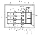
図1は本発明の第1実施例の主要部分を示す上面図であり、図2は第1実施例の構造を説明するための主要部分の断面図である。 FIG. 1 is a top view showing the main part of the first embodiment of the present invention, and FIG. 2 is a cross-sectional view of the main part for explaining the structure of the first embodiment.
分析基板10は図2に示すように第1基板60,第2基板63で構成されている。第1基板60の下面には、共通電極61が構成され、さらに撥水膜62で覆われている。第2基板63の上面には複数の制御電極64が配置され、その上を絶縁膜65,撥水膜66で覆われている。共通電極61および制御電極64は図示しない配線で制御装置12に接続している。第1基板60,共通電極61,撥水膜62,第2基板63,制御電極64,絶縁膜65,撥水膜66は全て光を透過する材料でできている。分析基板10の端面はスペーサ67で封止されており、第1基板60と第2基板63の間は0.5mm の隙間をもって隔てられている。この隙間には、水溶液と混じり合わないオイル71が満たされ、水溶性の液滴70が保持される。
The
また、第1基板60には注入ポート16,排液ポート48,光度計50が配置され、第2基板63の下には光度計50に対向して光源52が配置されている。
An
注入ポート16はサンプルポート24,希釈ポート25,第1試薬ポート31,第2試薬ポート37を代表するものであり、それらは同様の構造をしている。注入ポート16には内面が撥水膜で覆われて貫通した穴があり、プローブ15が挿入される。プローブ15は図示しない送液ポンプに接続し、先端から特定量の液を吐出する。第2基板63の注入ポート16の下の部分には液溜め85を形成する電極がある。
The
排液ポート48は分析基板10から上に突き出て、穴が貫通している。更に側面から排液チューブ47が貫入している。内部には空間がある。
The
図1に示すように分析基板10には、1列に並んだ制御電極64で構成される反応電極列56が4本配置されている。それぞれの反応電極列56には2箇所の攪拌電極列55が含まれ、攪拌電極列55には第1試薬ポート31および第2試薬ポート37から分取電極列54が接続している。また、2箇所に光度計50が配置されている。反応電極列56の一方の端は排液ポート48まで電極列で接続されている。他方の端は搬送電極列57に接続され、搬送電極列57にはサンプルポート24,希釈ポート25,排液ポート48,バッファ電極列58と電極列で接続している。サンプルポート24と希釈ポート25の間には希釈電極列59が配置されている。分析基板10の周囲はスペーサ67で封止されている。
As shown in FIG. 1, four
搬送電極列57は2本の電極列で構成され、途中で分岐して反応電極列56に接続している。バッファ電極列58は3本の電極列で構成され、終端が搬送電極列57および排液ポート48に接続している。また途中に分岐があり、そこからも搬送電極列57に接続している。
The
制御装置12は電気的に分析基板10の各電極と接続し、更に装置全体の各機構および表示装置13に接続している。
The
次に、第1実施例の動作を説明する。 Next, the operation of the first embodiment will be described.
分析される検体は、サンプルポート24からプローブ15によって注入される。液滴には、撥水膜62,66およびオイルにより排斥される力が働くが、共通電極61と制御電極64の間に電圧が印加されているときはエレクトロウェッチング力により制御電極64の上に広がる力が働く。液滴注入時は液溜め85の電極に電圧が印加されており、吐出された検体液は液滴として液溜め85の上の撥水膜62,66に挟まれたオイルの満たされた領域に入り込む。検体を吐出したプローブ15は、サンプルポート24から引き抜かれて洗浄され、別の検体の分注を行う。
The analyte to be analyzed is injected by the
液滴は、液溜め85から連なる2つの電極に電圧を印加して引き伸ばしてから、間の電極の電圧印加を削除することによって、電極1つのサイズで決定される一定量の小さな液滴に分割される。分割された液滴は、電圧を印加する電極を1つずつ移動することにより、搬送される。検体から分割された液滴は希釈電極列59に搬送される。液溜め85に残った液滴は、排液ポート48に搬送される。
The droplets are stretched by applying a voltage to the two electrodes connected from the
希釈液は希釈ポート25から挿入され、これも分取電極列54により一定量の液滴に分割されて希釈電極列59に搬送される。
The dilution liquid is inserted from the
希釈電極列59では検体液滴と希釈液を混合し、環状の電極列上で回転させることで攪拌して均一な希釈検体の液滴を形成する。図1の場合は混合攪拌を2段階実施し、異なる濃度を希釈検体を作製できる。希釈検体の液滴は更に小さな液滴に分割される。希釈検体の分割された液滴は、その検体で必要な項目数だけ、搬送電極列57を経由して選ばれた反応電極列56に搬送されると同時に、定められた数の液滴がバッファ電極列58に搬送される。
In the diluted
分析する項目に対応する試薬が、第1試薬ポート31および第2試薬ポート37から注入される。第1試薬ポート31から注入された試薬液滴は、液溜め85で蓄えられたあと、分取電極列54で一定量の液滴に分割される。分割された試薬液滴は、搬送電極列57から搬送されてきた希釈検体の液滴と混合し、攪拌電極列55の電極上で回転して攪拌される。攪拌された混合液は、一定時間ごとに1電極ずつ反応電極列56上を移動する。光度計50の位置に達したとき、光源52から照射された光が液滴を透過した量を光度計
50で検出し、結果を制御装置12に送信する。
A reagent corresponding to the item to be analyzed is injected from the
第2試薬ポート37から注入された試薬液滴も、分取電極列54で一定量の液滴に分割された後、反応電極列56上を搬送されてくる混合液の液滴に結合し、攪拌電極列55で攪拌される。第2試薬と混合した混合液滴も、反応電極列56上を1電極ずつ移動し、光度計50の位置に達したときに光学的検出を行い、結果は制御装置12に送られる。混合液滴は、排液ポート48に搬送される。
The reagent droplets injected from the
排液ポート48に到達した液滴は、オイル71との比重の違いにより浮き上がり、廃液73として排液チューブ47に吸引されて排出される。
The liquid droplets that have reached the
バッファ電極列58に搬送された希釈検体の液滴は、一定時間間隔ごとに1電極分ずつ移動させられる。2電極分の間隔を空けて、次の液滴が搬送される。
The diluted specimen droplets transported to the
制御装置12は光度計50からの信号を受け取り、特定成分の濃度を演算して表示装置13に送信すると同時に、演算結果から再検査が必要かどうかを判定する。再検査が必要なのは、例えば得られた濃度が好適な分析が可能な範囲を超えた場合などで、その場合は検体の希釈率を高くしての再検査が必要である。
The
再検査が必要と判断された場合、バッファ電極列58を搬送されている希釈検体液滴が、搬送電極列57を経由して反応電極列56に搬送され、再度分析が実施される。
When it is determined that reexamination is necessary, the diluted specimen droplets transported through the
再検査が必要ないと判断された検体の希釈液滴はバッファ電極列58を通過後排液ポート48に搬送されて排出される。
The diluted liquid droplet of the specimen that is determined not to be retested passes through the
本実施例の場合は、再検査の可能性のある検体を、反応しないオイルに包まれた液滴を形成して待機させるので、待機中の検体は周囲空気から隔離されており、空気中の酸素,二酸化炭素などとの反応や蒸発による変質を受けることがなく、精度の高い再検査を実施することが可能である。 In the case of the present embodiment, a specimen that may be retested is made to wait by forming a droplet wrapped in non-reacting oil, so that the waiting specimen is isolated from the surrounding air, It is possible to carry out re-examination with high accuracy without being affected by reaction with oxygen, carbon dioxide, etc., or alteration due to evaporation.
また、本実施例の場合は、分析基板内に再検査用の検体を待機させる領域を持つため、分析基板に分注した後の検体を待機し、再検査時に帰還させる機構が不要であり、装置の小形化と低コスト化が実現可能である。 In addition, in the case of the present embodiment, since there is a region for waiting for a sample for retesting in the analysis substrate, a mechanism for waiting for the sample after being dispensed to the analysis substrate and returning it at the time of retesting is unnecessary. It is possible to reduce the size and cost of the apparatus.
また、本実施例の場合は、検体を希釈した液滴を再検用に待機させるため、再検で必要とする検体の量が少なくてすみ、検体必要量の小さい分析装置が実現可能である。 Further, in the case of the present embodiment, since the sample-diluted liquid droplet is put on standby for re-examination, the amount of sample required for re-examination can be reduced, and an analyzer with a small amount of sample required can be realized.
また、本実施例の場合は、バッファ電極列58が複数列並んでいるため、狭いスペースで多くの液滴を待機させることができ、装置の小形化が可能である。
In the case of the present embodiment, since a plurality of
また、本実施例の場合は、バッファ電極列58の途中にも液滴を取り出す電極列が設けてあるので、再検査の必要が確定した検体が他の待機液滴よりも後ろにある場合でも、先に再検査を実施することができ、結果を早く出力できる分析装置を実現できる。
In the case of the present embodiment, an electrode array for taking out droplets is also provided in the middle of the
また、本実施例の場合、濃度の異なる希釈検体を作製できるので、最初の分析と濃度の異なる希釈検体を再検査用に待機させておくことが可能で、好適な濃度の希釈検体で再検査ができるので、高い精度の分析が可能である。 In the case of the present embodiment, since a diluted sample having a different concentration can be prepared, a diluted sample having a different concentration from the initial analysis can be kept on standby for retesting, and a retested with a diluted sample having a suitable concentration is possible. Therefore, high-precision analysis is possible.
また、本実施例の場合、それぞれの検体に対して複数の項目の濃度分析が可能であるが、再検査用の待機液滴の数は分析項目数より少なくすることが可能であり、バッファ電極列58の必要容量を少なくして小型の装置を提供することができる。
In the case of the present embodiment, concentration analysis of a plurality of items can be performed for each specimen, but the number of standby droplets for retesting can be smaller than the number of analysis items, and the buffer electrode The required capacity of the
図3は本発明の第2実施例のバッファ電極列の部分を示す上面図である。第1実施例との主な違いは、液溜め85がサンプルポート24とは別の場所に設置されており、バッファ電極列の中にも液溜め85′が含まれる点である。
FIG. 3 is a top view showing a portion of the buffer electrode array of the second embodiment of the present invention. The main difference from the first embodiment is that the
この場合は、サンプルポート24から注入された検体液滴は搬送電極列57に接続する液溜め85と、バッファ電極列58内の選ばれた液溜め85の両方に搬送される。搬送電極列57に接続する液溜め85からは一定量ずつ液滴が分割されて搬送電極列57に搬送され、分析が行われる。バッファ電極列58内の液溜め85に搬送された検体は、その検体の再検査の要否が確定するまで待機し、再検査が必要な場合は液滴を分割して搬送電極列57に搬送して再検査を実施する。残された検体液滴は排液ポート48に搬送されて排出される。
In this case, the specimen droplet injected from the
本実施例の場合は、バッファ電極列58の中に複数分の待機領域が用意されているので、複数の検体を待機させておくことができる。
In the case of the present embodiment, since a plurality of standby areas are prepared in the
また、本実施例の場合は、待機中は液溜め85に留めておくので、継続的に移動する必要がなく、単純な制御で行え、信頼性が高い。
In the case of the present embodiment, since it is kept in the
また、本実施例の場合は、検体を分析基板10に注入したときに再検査用の液滴まで分割することがないので、液滴の分割に要する時間を短縮することができ、高い処理能力の分析装置が実現できる。
Further, in the case of the present embodiment, when the specimen is injected into the
図4から図7は本発明の第3実施例の説明図である。図4は全体の概略を示す斜視図、図5は分析基板の概略構成を示す上面図、図6は分析流路の要部を示す上面図、図7はサンプルポートの要部を示す断面図である。 4 to 7 are explanatory views of a third embodiment of the present invention. 4 is a perspective view showing the outline of the whole, FIG. 5 is a top view showing a schematic configuration of the analysis substrate, FIG. 6 is a top view showing the main part of the analysis flow path, and FIG. 7 is a cross-sectional view showing the main part of the sample port. It is.
リング状の分析基板10の周囲に試薬ディスク41,第1試薬プローブ30,第2試薬プローブ35,サンプルディスク20,サンプルプローブ22,制御装置12,表示装置13が配置されている。分析基板10の内側には移動機構51に支持された光度計50が配置されている。試薬ディスク41には複数の試薬容器40が搭載されている。サンプルディスク20には複数のサンプル容器21が搭載されている。第1試薬プローブ30,第2試薬プローブ35,サンプルプローブ22はそれぞれ独立して上下動,回転が可能である。それぞれのプローブは図示しないシリンジポンプに接続されている。プローブの移動経路に第1試薬ポート31,第2試薬ポート37,サンプルポート24、および洗浄ポート26が配置されている。サンプルポート24に近接して希釈ポート25が設置されている。また、分析基板10には4つの排液ポート48が設けられ、それらには排液チューブ47が接続されている。
A reagent disk 41, a
光度計50は、広い波長範囲の光を放射する光源と、回折格子と、複数の波長の光を検出する検出器が内蔵されている。
The
分析基板10の構造を図5で説明する。半径方向にのびた複数の分析流路80が円周状に多数並んでいる。分析流路80に交差して、周方向に排液流路81,第2試薬流路82,サンプル流路83,第1試薬流路84が並んでいる。第1試薬流路84の外側には、サンプルポート24,希釈ポート25,第1試薬ポート31,第2試薬ポート37,複数の排液ポート48が配置されている。
The structure of the
図6により、分析基板10の電極配置を説明する。図で、実線の四角い枠は、それぞれ制御電極64を示す。分析流路80は半径方向に並んだa1からa23まで23個の電極で構成されている。本実施例の場合、個々の電極は一辺が約2.8mm の正方形である。電極a1,a3,a5,a12は、隣の分析流路との間に中継電極88が配置され、周方向に搬送流路である第1試薬流路84,サンプル流路83,第2試薬流路82,排液流路
81を形成している。また電極a18,a19,a20の部分は測光領域である。
The electrode arrangement of the
図7により、希釈ポートの構造を説明する。サンプルポート24に近接して設置されている希釈ポート25は、サンプルポート24と同様に分析基板10から上に突き出ており、希釈液プローブ23が挿入される。希釈液プローブ23は図示しない希釈液ポンプに接続されており、量を制御して希釈液を吐出することができる。
The structure of the dilution port will be described with reference to FIG. The
つぎに本実施例の動作を説明する。 Next, the operation of this embodiment will be described.
試薬ディスク41には、個々の分析項目に対応して第1試薬と第2試薬の2種類の試薬が試薬容器40に入れられて搭載される。
Two types of reagents, a first reagent and a second reagent, are placed in the
ある項目の試薬の分析基板10への分注は次のように行われる。その項目の第1試薬が入った試薬容器40が第1試薬プローブ30の吸引位置に来るように41を回転し、第1試薬プローブ30で第1試薬を80マイクロリットル吸引する。第1試薬プローブ30は上昇,回転して、第1試薬ポート31に挿入される。挿入後、試薬を8マイクロリットルずつ10回に分けて吐出する。試薬吐出と連動して制御電極64に順次電圧が印加され、吐出された試薬は液滴となって第1試薬流路84まで搬送され、第1試薬流路84上を周回する。
Dispensing a certain item of reagent to the
第2試薬に対しても第1試薬の場合と同様の動作で、第2試薬プローブ35で試薬容器40から第2試薬を40マイクロリットル吸引し、第2試薬ポート37から4マイクロリットルずつ10回に分けて吐出し、液滴として第2試薬流路82に移動し、第2試薬流路82上を周回する。
The second reagent is aspirated by 40 microliters of the second reagent from the
第1試薬プローブ30および第2試薬プローブ35はそれぞれ試薬吐出後、洗浄ポート26に移動し、洗浄水でプローブ内面,外面を洗浄される。
After the reagent is discharged, the
分析する予定の項目の第1試薬および第2試薬について引き続き分注が行われ、それぞれの試薬が液滴として第1試薬流路84および第2試薬流路82上を周回する。
Dispensing is continuously performed for the first reagent and the second reagent of the item to be analyzed, and each reagent circulates on the
サンプルディスク20にはキャリブレーションおよび精度管理用の濃度既知の検体,被分析検体がサンプル容器21に入れられて搭載される。
A
検体の分析基板10への分注は次のように行われる。目的の検体が入ったサンプル容器21がサンプルプローブ22の吸引位置に来るようにサンプルディスク20が回転し、サンプルプローブ22がサンプル容器21から検体を吸引する。吸引量はその検体で分析する全項目のテストおよび再検査に必要な量以上である。サンプルプローブ22は上昇,回転し、サンプルポート24に挿入される。挿入後、吸引した検体を吐出する。このとき希釈ポート25から希釈液を吐出し、検体液75は希釈液76の中に吐出されるようにする。吐出する希釈液と検体液の量は、行われる分析の種類によって調整される。吐出は、その検体で分析が行われる回数と、再検査用の分が行われ、希釈液と検体液が混合した液滴は、第2試薬流路82に搬送され、第2試薬流路82上を周回する。サンプルプローブ
22は、分注後洗浄ポート26に移動し、洗浄水でプローブ内面,外面を洗浄される。
The dispensing of the sample to the
ある検体のある項目の分析は次のように行われる。 An analysis of an item of a sample is performed as follows.
制御装置12により、ある検体のある項目の分析を実施する分析流路80が選ばれる。選ばれた分析流路80に周回している希釈検体,試薬の液滴が移動し、まず希釈検体液滴はa10に、第1試薬液滴はa7,a8に保持される。次にa10から印加電極を順次移動することで検体液滴をa20まで搬送する。続いて、a7,a8の印加電極を順次移動することで第1試薬液滴をa18,a19まで搬送する。ここで、検体と第1試薬の液滴は合体し、第1反応液となって3つの電極a18,a19,a20上に保持される。次にa16からa23の間で電圧を印加している位置を往復移動することで、液滴は往復運動し、第1反応液の液滴中の検体と第1試薬は攪拌されて均一になる。その後印加電極は
a18,a19,a20に固定されて、第1反応時間の5分間液滴は保持される。
The
光度計50は移動機構51により30秒で1回転の速度で旋回する。分析流路80上を通過するとき、a18,a19,a20上の液滴に光を照射し、選ばれた波長の透過光量を測定し、制御装置12に送信する。制御装置12では吸光度を演算する。第1反応時間間、周期的に測定が行われる。
The
第1反応時間の間に、第2試薬が準備される。第2試薬流路82上を周回している試薬液滴が、選ばれた分析流路80の電極a14まで搬送される。
A second reagent is prepared during the first reaction time. The reagent droplets circulating around the
第1反応時間経過後、第2試薬の液滴は、印加電極をa14から順次移動してa18に搬送される。ここで第2試薬は第1反応液と合体し、第2反応液となる。次にa16からa23の間で電圧を印加している位置を往復移動することで、液滴は往復運動し、第2反応液は攪拌されて均一になる。その後印加電極はa18,a19,a20,a21に固定されて、第2反応時間の5分間液滴は保持される。第2反応時間の間も光度計による周期的な測定が行われる。 After the first reaction time has elapsed, the droplets of the second reagent are transported to a18 by sequentially moving the application electrode from a14. Here, the second reagent is combined with the first reaction solution to become the second reaction solution. Next, by reciprocating the position where a voltage is applied between a16 and a23, the droplet reciprocates, and the second reaction liquid is stirred and becomes uniform. Thereafter, the application electrode is fixed to a18, a19, a20, a21, and the droplet is held for 5 minutes in the second reaction time. Periodic measurement with a photometer is also performed during the second reaction time.
第2反応時間の後、第2反応液の液滴は排液流路81を通る経路を通り、排液ポート
48まで搬送される。第2反応液の液滴70は撥水膜62,69との表面力により、排液ポート48の内部に入り込み、オイル71との比重の違いで浮き上がる。浮き上がった廃液73は排液チューブ47に吸引されて排出される。
After the second reaction time, the droplet of the second reaction liquid passes through the path through the
分析は、複数の分析流路80で並列して進められる。また、第2反応時間の間に、次の分析のための検体と第1試薬の液滴が電極a10およびa7,a8に待機し、分析が終了して第2反応液を排出した後すぐに次の分析が開始する。
The analysis proceeds in parallel in the plurality of
制御装置12では、分析項目毎にキャリブレーション用の検体の分析で得られた吸光度の変化と濃度との関係を導出し、キャリブレーションデータとして格納するまた、定期的に精度管理用の検体の分析を実施し、その結果が所定の範囲に入らない場合は異常のアラームを表示装置13に送信する。被分析検体に対しては、キャリブレーションデータを用いて分析項目の濃度を演算し、表示装置13に送信して表示する。濃度の演算結果が所定の範囲から外れている場合は、再検査が実行される。再検査は、サンプル流路83を周回している希釈検体の液滴で実行される。再検査が行われる希釈検体は、最初の分析の場合と異なった希釈率のものが選ばれることもある。
The
サンプル流路83を周回している希釈検体液滴で、その検体の再検査の必要がないと確定したものは、排液ポート48に搬送されて、排出される。
Diluted specimen droplets circulating around the
本実施例の場合も、再検査の可能性のある検体を、反応しないオイルに包まれた液滴を形成して待機させるので、待機中の検体は周囲空気から隔離されており、空気中の酸素,二酸化炭素などとの反応や蒸発による変質を受けることがなく、精度の高い再検査を実施することが可能である。 In the case of the present embodiment as well, specimens that may be retested are made to stand by forming droplets wrapped in non-reacting oil, so that the waiting specimen is isolated from the surrounding air, It is possible to carry out re-examination with high accuracy without being affected by reaction with oxygen, carbon dioxide, etc., or alteration due to evaporation.
また、本実施例の場合は、検体液滴の搬送流路が検体液滴の待機領域を兼ねているので、待機領域を特別に設ける必要がなく、装置の小形化が実現できる。 In the case of the present embodiment, since the specimen droplet transport channel also serves as a specimen droplet standby area, it is not necessary to provide a special standby area, and the apparatus can be miniaturized.
また、本実施例の場合、待機液滴が円周上のサンプル流路83を周回しているので、再検査が必要と確定したとき、近くの空いている分析流路80ですぐに分析を開始することができ、分析の結果を早く出力することができる。
Further, in the case of the present embodiment, since the standby droplets circulate around the
10…分析基板、12…制御装置、13…表示装置、15…プローブ、16…注入ポート、24…サンプルポート、25…希釈ポート、31…第1試薬ポート、37…第2試薬ポート、47…排液チューブ、48…排液ポート、50…光度計、52…光源、54…分取電極列、55…攪拌電極列、56…反応電極列、57…搬送電極列、58…バッファ電極列、59…希釈電極列、60…第1基板、61…共通電極、62,66,68…撥水膜、63…第2基板、64…制御電極、65…絶縁膜、67…スペーサ、70…液滴、71…オイル、73…廃液、75…検体液、76…希釈液、80…分析流路、81…排液流路、82…第2試薬流路、83…サンプル流路、84…第1試薬流路、85…液溜め、88…中継電極。
DESCRIPTION OF
Claims (7)
前記少なくとも1対の板状部材の少なくとも一方に、液体を搬送する方向に沿って複数の電極を所定間隔で配置した液体搬送路を複数備え、
かつ該液体搬送路には、少なくともサンプル液体を搬送するサンプル搬送路と、該サンプル搬送路に試薬を供給する試薬搬送路と、を備えた液体搬送機構と、
前記サンプル搬送路に検体を供給する検体分配機構と、
前記試薬搬送路に試薬を供給する試薬分配機構と、
前記液体搬送路中での検体と試薬の反応を光学的に分析する測定機構と、
を備え、
更に、前記試薬分配機構が前記サンプル搬送路に試薬を供給する位置より、前記検体分配機構が前記サンプル搬送路に検体を供給する位置の側に、前記検体分配機構から供給された複数の検体を保持し、かつ保持している検体を前記サンプル搬送路に複数の位置で供給する搬送路を備えたバッファ電極列を備えたことを特徴とする自動分析装置。 A liquid transport mechanism comprising at least one pair of plate-like members facing each other at a predetermined interval and holding a liquid in a gap,
At least one of the at least one pair of plate-like members includes a plurality of liquid transport paths in which a plurality of electrodes are arranged at predetermined intervals along the direction of transporting the liquid,
The liquid transport path includes at least a sample transport path for transporting a sample liquid, and a reagent transport path for supplying a reagent to the sample transport path,
A sample distribution mechanism for supplying a sample to the sample transport path;
A reagent distribution mechanism for supplying a reagent to the reagent transport path;
A measurement mechanism for optically analyzing the reaction between the specimen and the reagent in the liquid conveyance path;
With
Further, a plurality of samples supplied from the sample distribution mechanism are arranged closer to a position where the sample distribution mechanism supplies a sample to the sample conveyance path than a position where the reagent distribution mechanism supplies a reagent to the sample conveyance path. An automatic analyzer comprising a buffer electrode array having a transport path for holding and supplying the held specimen to the sample transport path at a plurality of positions.
前記サンプル搬送路は異なる検体を並行して搬送できるよう複数設けられ、前記バッファ電極列は、複数の該サンプル搬送路間で連結されていることを特徴とする自動分析装置。 The automatic analyzer according to claim 1, wherein
2. The automatic analyzer according to claim 1, wherein a plurality of the sample transport paths are provided so that different specimens can be transported in parallel, and the buffer electrode array is connected between the plurality of sample transport paths.
前記バッファ電極列は並行して複数設けられ、更に複数のバッファ電極列を接続する少なくとも1列の電極列を備えたことを特徴とする自動分析装置。 The automatic analyzer according to claim 2,
2. An automatic analyzer comprising a plurality of the buffer electrode rows provided in parallel, and further comprising at least one electrode row for connecting the plurality of buffer electrode rows.
前記バッファ電極列には複数回分の分析が実行可能な検体を蓄えることが可能なサンプル溜めが接続されていることを特徴とする自動分析装置。 The automatic analyzer according to claim 2 or 3,
A sample reservoir capable of storing a sample that can be analyzed a plurality of times is connected to the buffer electrode array.
前記測定機構での分析結果に基づき、再検査の要否を判断する判断手段と、
該判断手段が特定検体の特定分析項目での再検査が必要と判断した場合は、前記バッファ電極列に保持された前記特定検体と同一の検体が前記サンプル搬送路に搬送されるようにバッファ電極列を制御する制御手段とを備えたことを特徴とする自動分析装置。 In the automatic analyzer in any one of Claims 1-4,
A determination means for determining the necessity of re-examination based on the analysis result in the measurement mechanism;
When the determination means determines that reexamination of a specific sample with a specific analysis item is necessary, the buffer electrode is arranged so that the same sample as the specific sample held in the buffer electrode row is transported to the sample transport path An automatic analyzer comprising control means for controlling the columns .
前記検体分配機構の近傍に検体の希釈液を供給する希釈液供給機構を備え、
該検体分配機構がサンプル搬送路に検体を供給する際に、該希釈液供給機構が該サンプル搬送路に希釈液を供給することにより、希釈した検体をサンプル搬送路内で生成し、希釈された検体を前記バッファ電極列に保持するよう制御する制御手段を備えたことを特徴とする自動分析装置。 The automatic analyzer according to claim 5,
Provided with a diluent supply mechanism for supplying a sample diluent in the vicinity of the sample distribution mechanism,
When the specimen distribution mechanism supplies the specimen to the sample transport path, the diluted liquid supply mechanism supplies the diluent to the sample transport path, thereby generating a diluted specimen in the sample transport path and diluting it. An automatic analyzer comprising control means for controlling to hold a sample in the buffer electrode array .
前記サンプル搬送路は放射状に形成され、かつ前記試薬搬送路は、該サンプル搬送路を横断して、複数の該サンプル搬送路に試薬を供給可能に形成されていることを特徴とする自動分析装置。 In the automatic analyzer in any one of Claims 1-6,
The autoanalyzer is characterized in that the sample transport paths are formed radially, and the reagent transport paths are formed so as to be able to supply reagents to the plurality of sample transport paths across the sample transport paths. .
Priority Applications (2)
| Application Number | Priority Date | Filing Date | Title |
|---|---|---|---|
| JP2005167632A JP4969060B2 (en) | 2005-06-08 | 2005-06-08 | Automatic analyzer |
| PCT/JP2006/311278 WO2006132211A1 (en) | 2005-06-08 | 2006-06-06 | Automatic analyzing instrument |
Applications Claiming Priority (1)
| Application Number | Priority Date | Filing Date | Title |
|---|---|---|---|
| JP2005167632A JP4969060B2 (en) | 2005-06-08 | 2005-06-08 | Automatic analyzer |
Publications (2)
| Publication Number | Publication Date |
|---|---|
| JP2006343163A JP2006343163A (en) | 2006-12-21 |
| JP4969060B2 true JP4969060B2 (en) | 2012-07-04 |
Family
ID=37498412
Family Applications (1)
| Application Number | Title | Priority Date | Filing Date |
|---|---|---|---|
| JP2005167632A Expired - Fee Related JP4969060B2 (en) | 2005-06-08 | 2005-06-08 | Automatic analyzer |
Country Status (2)
| Country | Link |
|---|---|
| JP (1) | JP4969060B2 (en) |
| WO (1) | WO2006132211A1 (en) |
Families Citing this family (24)
| Publication number | Priority date | Publication date | Assignee | Title |
|---|---|---|---|---|
| EP1859330B1 (en) | 2005-01-28 | 2012-07-04 | Duke University | Apparatuses and methods for manipulating droplets on a printed circuit board |
| US20140193807A1 (en) | 2006-04-18 | 2014-07-10 | Advanced Liquid Logic, Inc. | Bead manipulation techniques |
| US9476856B2 (en) | 2006-04-13 | 2016-10-25 | Advanced Liquid Logic, Inc. | Droplet-based affinity assays |
| US7439014B2 (en) | 2006-04-18 | 2008-10-21 | Advanced Liquid Logic, Inc. | Droplet-based surface modification and washing |
| US7727723B2 (en) | 2006-04-18 | 2010-06-01 | Advanced Liquid Logic, Inc. | Droplet-based pyrosequencing |
| US7901947B2 (en) | 2006-04-18 | 2011-03-08 | Advanced Liquid Logic, Inc. | Droplet-based particle sorting |
| US8637324B2 (en) | 2006-04-18 | 2014-01-28 | Advanced Liquid Logic, Inc. | Bead incubation and washing on a droplet actuator |
| US8809068B2 (en) | 2006-04-18 | 2014-08-19 | Advanced Liquid Logic, Inc. | Manipulation of beads in droplets and methods for manipulating droplets |
| US10078078B2 (en) | 2006-04-18 | 2018-09-18 | Advanced Liquid Logic, Inc. | Bead incubation and washing on a droplet actuator |
| EP2573562A3 (en) | 2007-02-09 | 2013-10-30 | Advanced Liquid Logic, Inc. | Droplet actuator devices and methods employing magnetic beads |
| JP2010524002A (en) * | 2007-04-10 | 2010-07-15 | アドヴァンスト リキッド ロジック インコーポレイテッド | Droplet dispensing apparatus and method |
| CA2709928A1 (en) | 2007-12-23 | 2009-07-09 | Advanced Liquid Logic, Inc. | Droplet actuator configurations and methods of conducting droplet operations |
| US8852952B2 (en) | 2008-05-03 | 2014-10-07 | Advanced Liquid Logic, Inc. | Method of loading a droplet actuator |
| US8926065B2 (en) | 2009-08-14 | 2015-01-06 | Advanced Liquid Logic, Inc. | Droplet actuator devices and methods |
| JP5610258B2 (en) * | 2009-09-09 | 2014-10-22 | 国立大学法人 筑波大学 | Liquid feeding device |
| WO2011057197A2 (en) | 2009-11-06 | 2011-05-12 | Advanced Liquid Logic, Inc. | Integrated droplet actuator for gel electrophoresis and molecular analysis |
| EP2516669B1 (en) | 2009-12-21 | 2016-10-12 | Advanced Liquid Logic, Inc. | Enzyme assays on a droplet actuator |
| WO2012154745A2 (en) | 2011-05-09 | 2012-11-15 | Advanced Liquid Logic, Inc. | Microfluidic feedback using impedance detection |
| WO2013009927A2 (en) | 2011-07-11 | 2013-01-17 | Advanced Liquid Logic, Inc. | Droplet actuators and techniques for droplet-based assays |
| WO2013078216A1 (en) | 2011-11-21 | 2013-05-30 | Advanced Liquid Logic Inc | Glucose-6-phosphate dehydrogenase assays |
| EP2867645B1 (en) | 2012-06-27 | 2019-06-05 | Advanced Liquid Logic, Inc. | Techniques and droplet actuator designs for reducing bubble formation |
| US9863913B2 (en) | 2012-10-15 | 2018-01-09 | Advanced Liquid Logic, Inc. | Digital microfluidics cartridge and system for operating a flow cell |
| CN113842962B (en) * | 2021-10-19 | 2023-02-17 | 安图实验仪器(郑州)有限公司 | Concentration uniformization microfluidic chip and concentration uniformization method based on electrowetting |
| CN118501132A (en) * | 2024-06-06 | 2024-08-16 | 江苏绿叶环保科技仪器有限公司 | Rapid detection analyzer and detection method for high concentration ammonia nitrogen in wastewater |
Family Cites Families (6)
| Publication number | Priority date | Publication date | Assignee | Title |
|---|---|---|---|---|
| JP2590678B2 (en) * | 1992-11-30 | 1997-03-12 | 株式会社島津製作所 | Biochemical automatic analyzer |
| JP3229915B2 (en) * | 1995-01-19 | 2001-11-19 | 日本電子株式会社 | Biochemical automatic analyzer |
| JP3558898B2 (en) * | 1998-11-05 | 2004-08-25 | 株式会社日立製作所 | Automatic analyzer and automatic analysis method |
| US6565727B1 (en) * | 1999-01-25 | 2003-05-20 | Nanolytics, Inc. | Actuators for microfluidics without moving parts |
| JP2002090375A (en) * | 2000-09-12 | 2002-03-27 | A & T:Kk | Clinical test system and control method for clinical test system |
| US6911132B2 (en) * | 2002-09-24 | 2005-06-28 | Duke University | Apparatus for manipulating droplets by electrowetting-based techniques |
-
2005
- 2005-06-08 JP JP2005167632A patent/JP4969060B2/en not_active Expired - Fee Related
-
2006
- 2006-06-06 WO PCT/JP2006/311278 patent/WO2006132211A1/en not_active Ceased
Also Published As
| Publication number | Publication date |
|---|---|
| WO2006132211A1 (en) | 2006-12-14 |
| JP2006343163A (en) | 2006-12-21 |
Similar Documents
| Publication | Publication Date | Title |
|---|---|---|
| JP4969060B2 (en) | Automatic analyzer | |
| JP4185904B2 (en) | Liquid transfer substrate, analysis system, and analysis method | |
| JP4890699B2 (en) | Analytical apparatus and method for measuring sample quality | |
| US4325910A (en) | Automated multiple-purpose chemical-analysis apparatus | |
| JP6576833B2 (en) | Automatic analyzer | |
| JP3984748B2 (en) | Chemical analyzer and chemical analysis system | |
| JP4111179B2 (en) | Chemical analyzer and chemical analysis system | |
| JP2010133870A (en) | Automatic analyzer and precision management method of automatic analyzer | |
| US11125738B2 (en) | Blood sample analysis systems and methods | |
| US11169169B2 (en) | Method of washing an aspiration probe of an in-vitro diagnostic system, in-vitro diagnostic method, and in-vitro diagnostic system | |
| JP6814171B2 (en) | Automatic analyzer | |
| JP5271929B2 (en) | Automatic analyzer | |
| JP2012026728A (en) | Analyzer | |
| US20060292038A1 (en) | Automated sample analyzer and cuvette | |
| JP4969061B2 (en) | Automatic analyzer | |
| JPS6327661B2 (en) | ||
| JP3268400B2 (en) | Mixed reactor | |
| JP2000235037A (en) | Sample analyzer | |
| CN110730910A (en) | Automatic analyzer | |
| JPS62217163A (en) | Automatic analyzing instrument | |
| JP2007322394A (en) | Dispensing device and automated analyzer | |
| JP2007316012A (en) | Autoanalyzer and specimen-dispensing method therefor | |
| JP5192316B2 (en) | Automatic analyzer | |
| US20250076330A1 (en) | Measuring chip, automatic analyzing apparatus, reaction cuvette, and automatic analyzing system | |
| JP6049671B2 (en) | Automatic analyzer and its dispensing probe |
Legal Events
| Date | Code | Title | Description |
|---|---|---|---|
| A621 | Written request for application examination |
Free format text: JAPANESE INTERMEDIATE CODE: A621 Effective date: 20071121 |
|
| A521 | Request for written amendment filed |
Free format text: JAPANESE INTERMEDIATE CODE: A523 Effective date: 20071121 |
|
| A131 | Notification of reasons for refusal |
Free format text: JAPANESE INTERMEDIATE CODE: A131 Effective date: 20101207 |
|
| A521 | Request for written amendment filed |
Free format text: JAPANESE INTERMEDIATE CODE: A523 Effective date: 20110124 |
|
| TRDD | Decision of grant or rejection written | ||
| A01 | Written decision to grant a patent or to grant a registration (utility model) |
Free format text: JAPANESE INTERMEDIATE CODE: A01 Effective date: 20120306 |
|
| A01 | Written decision to grant a patent or to grant a registration (utility model) |
Free format text: JAPANESE INTERMEDIATE CODE: A01 |
|
| A61 | First payment of annual fees (during grant procedure) |
Free format text: JAPANESE INTERMEDIATE CODE: A61 Effective date: 20120403 |
|
| FPAY | Renewal fee payment (event date is renewal date of database) |
Free format text: PAYMENT UNTIL: 20150413 Year of fee payment: 3 |
|
| R150 | Certificate of patent or registration of utility model |
Ref document number: 4969060 Country of ref document: JP Free format text: JAPANESE INTERMEDIATE CODE: R150 Free format text: JAPANESE INTERMEDIATE CODE: R150 |
|
| S531 | Written request for registration of change of domicile |
Free format text: JAPANESE INTERMEDIATE CODE: R313531 |
|
| S533 | Written request for registration of change of name |
Free format text: JAPANESE INTERMEDIATE CODE: R313533 |
|
| R350 | Written notification of registration of transfer |
Free format text: JAPANESE INTERMEDIATE CODE: R350 |
|
| LAPS | Cancellation because of no payment of annual fees |