JP4945571B2 - Bearing built into the boom - Google Patents
Bearing built into the boom Download PDFInfo
- Publication number
- JP4945571B2 JP4945571B2 JP2008542276A JP2008542276A JP4945571B2 JP 4945571 B2 JP4945571 B2 JP 4945571B2 JP 2008542276 A JP2008542276 A JP 2008542276A JP 2008542276 A JP2008542276 A JP 2008542276A JP 4945571 B2 JP4945571 B2 JP 4945571B2
- Authority
- JP
- Japan
- Prior art keywords
- bearing
- arm
- sliding
- boom
- box
- Prior art date
- Legal status (The legal status is an assumption and is not a legal conclusion. Google has not performed a legal analysis and makes no representation as to the accuracy of the status listed.)
- Active
Links
- 239000000463 material Substances 0.000 claims description 8
- 238000000034 method Methods 0.000 claims description 6
- 229910000897 Babbitt (metal) Inorganic materials 0.000 claims description 2
- 238000005553 drilling Methods 0.000 description 11
- 239000011435 rock Substances 0.000 description 7
- 229910000906 Bronze Inorganic materials 0.000 description 2
- 239000010974 bronze Substances 0.000 description 2
- 239000000969 carrier Substances 0.000 description 2
- KUNSUQLRTQLHQQ-UHFFFAOYSA-N copper tin Chemical compound [Cu].[Sn] KUNSUQLRTQLHQQ-UHFFFAOYSA-N 0.000 description 2
- 229910000831 Steel Inorganic materials 0.000 description 1
- 238000009412 basement excavation Methods 0.000 description 1
- 238000005452 bending Methods 0.000 description 1
- 230000007423 decrease Effects 0.000 description 1
- 230000001419 dependent effect Effects 0.000 description 1
- 230000000694 effects Effects 0.000 description 1
- 239000002184 metal Substances 0.000 description 1
- 238000003672 processing method Methods 0.000 description 1
- 239000010959 steel Substances 0.000 description 1
Images



Classifications
-
- B—PERFORMING OPERATIONS; TRANSPORTING
- B66—HOISTING; LIFTING; HAULING
- B66C—CRANES; LOAD-ENGAGING ELEMENTS OR DEVICES FOR CRANES, CAPSTANS, WINCHES, OR TACKLES
- B66C23/00—Cranes comprising essentially a beam, boom, or triangular structure acting as a cantilever and mounted for translatory of swinging movements in vertical or horizontal planes or a combination of such movements, e.g. jib-cranes, derricks, tower cranes
- B66C23/62—Constructional features or details
- B66C23/64—Jibs
- B66C23/70—Jibs constructed of sections adapted to be assembled to form jibs or various lengths
- B66C23/701—Jibs constructed of sections adapted to be assembled to form jibs or various lengths telescopic
- B66C23/707—Jibs constructed of sections adapted to be assembled to form jibs or various lengths telescopic guiding devices for telescopic jibs
-
- E—FIXED CONSTRUCTIONS
- E21—EARTH OR ROCK DRILLING; MINING
- E21B—EARTH OR ROCK DRILLING; OBTAINING OIL, GAS, WATER, SOLUBLE OR MELTABLE MATERIALS OR A SLURRY OF MINERALS FROM WELLS
- E21B7/00—Special methods or apparatus for drilling
- E21B7/02—Drilling rigs characterised by means for land transport with their own drive, e.g. skid mounting or wheel mounting
-
- B—PERFORMING OPERATIONS; TRANSPORTING
- B66—HOISTING; LIFTING; HAULING
- B66C—CRANES; LOAD-ENGAGING ELEMENTS OR DEVICES FOR CRANES, CAPSTANS, WINCHES, OR TACKLES
- B66C23/00—Cranes comprising essentially a beam, boom, or triangular structure acting as a cantilever and mounted for translatory of swinging movements in vertical or horizontal planes or a combination of such movements, e.g. jib-cranes, derricks, tower cranes
- B66C23/62—Constructional features or details
- B66C23/64—Jibs
- B66C23/70—Jibs constructed of sections adapted to be assembled to form jibs or various lengths
- B66C23/701—Jibs constructed of sections adapted to be assembled to form jibs or various lengths telescopic
-
- F—MECHANICAL ENGINEERING; LIGHTING; HEATING; WEAPONS; BLASTING
- F16—ENGINEERING ELEMENTS AND UNITS; GENERAL MEASURES FOR PRODUCING AND MAINTAINING EFFECTIVE FUNCTIONING OF MACHINES OR INSTALLATIONS; THERMAL INSULATION IN GENERAL
- F16C—SHAFTS; FLEXIBLE SHAFTS; ELEMENTS OR CRANKSHAFT MECHANISMS; ROTARY BODIES OTHER THAN GEARING ELEMENTS; BEARINGS
- F16C25/00—Bearings for exclusively rotary movement adjustable for wear or play
- F16C25/02—Sliding-contact bearings
-
- F—MECHANICAL ENGINEERING; LIGHTING; HEATING; WEAPONS; BLASTING
- F16—ENGINEERING ELEMENTS AND UNITS; GENERAL MEASURES FOR PRODUCING AND MAINTAINING EFFECTIVE FUNCTIONING OF MACHINES OR INSTALLATIONS; THERMAL INSULATION IN GENERAL
- F16C—SHAFTS; FLEXIBLE SHAFTS; ELEMENTS OR CRANKSHAFT MECHANISMS; ROTARY BODIES OTHER THAN GEARING ELEMENTS; BEARINGS
- F16C29/00—Bearings for parts moving only linearly
- F16C29/02—Sliding-contact bearings
-
- F—MECHANICAL ENGINEERING; LIGHTING; HEATING; WEAPONS; BLASTING
- F16—ENGINEERING ELEMENTS AND UNITS; GENERAL MEASURES FOR PRODUCING AND MAINTAINING EFFECTIVE FUNCTIONING OF MACHINES OR INSTALLATIONS; THERMAL INSULATION IN GENERAL
- F16C—SHAFTS; FLEXIBLE SHAFTS; ELEMENTS OR CRANKSHAFT MECHANISMS; ROTARY BODIES OTHER THAN GEARING ELEMENTS; BEARINGS
- F16C29/00—Bearings for parts moving only linearly
- F16C29/12—Arrangements for adjusting play
Landscapes
- Engineering & Computer Science (AREA)
- General Engineering & Computer Science (AREA)
- Mechanical Engineering (AREA)
- Mining & Mineral Resources (AREA)
- Life Sciences & Earth Sciences (AREA)
- Geology (AREA)
- Geochemistry & Mineralogy (AREA)
- General Life Sciences & Earth Sciences (AREA)
- Physics & Mathematics (AREA)
- Fluid Mechanics (AREA)
- Environmental & Geological Engineering (AREA)
- Jib Cranes (AREA)
- Bearings For Parts Moving Linearly (AREA)
- Earth Drilling (AREA)
- Sliding-Contact Bearings (AREA)
- Forklifts And Lifting Vehicles (AREA)
Description
本発明は、入れ子式に伸長可能なブームに組込まれた軸受に関する。特に、本明細書に記載するブームは、削岩機器を支持する削岩機に関連したブームに関するものである。 The present invention relates to a bearing incorporated in a telescopic boom. In particular, the boom described herein relates to a boom associated with a rock drill that supports rock drilling equipment.
上記形式のブームは、例えば掘削機器の装着される上記のブームを備えたキャリアから成り得る掘削機に関連して用いられる。キャリアにはこのような複数のブームが設けられる。この形式の掘削機は公知であり、ここでは説明しない。かかるブームに設けられる穿孔装置の使用し易さや範囲を高めるために、ブームは通常入れ子式手段によって伸長でき、本明細書では入れ子式に伸長可能なと記載する。このことは、ブームが互いに軸方向に変位できる二つ以上のアームを備えていることを意味している。 Booms of the above type are used in connection with excavators that can consist of a carrier with the above boom, for example, to which excavation equipment is mounted. The carrier is provided with such a plurality of booms. This type of excavator is known and will not be described here. In order to increase the ease of use and the range of the drilling device provided in such a boom, the boom can be normally extended by a telescopic means, and is described herein as being telescopically extendable. This means that the boom includes two or more arms that can be displaced axially with respect to each other.
先行技術によれば、このような入れ子式のブームは、通常、直径の異なる二本の管から成る筒状アームで構成されている。直径の小さい内側アームを構成する内側管は、直径の大きな外側アームを構成する外側管内で変位できる。このような筒状アームは相互に嵌合するようにされている。その結果、これらアームは寸法上の誤差を小さく設計され、互いにしっかりと支持されている。しかし、この構成は精密で高価な処理方法を必要としている。 According to the prior art, such a telescoping boom is usually composed of a cylindrical arm consisting of two tubes with different diameters. The inner tube constituting the smaller diameter inner arm can be displaced within the outer tube constituting the larger diameter outer arm. Such cylindrical arms are adapted to be fitted to each other. As a result, the arms are designed with small dimensional errors and are firmly supported on each other. However, this configuration requires a precise and expensive processing method.
最近では、このような入れ子式ブームに関連して標準の冷間圧延管、好ましくは標準形式の方形管を用いるのが望ましくなってきている。外側管の内側寸法(管の横断面における高さ及び幅)は、許容誤差を比較的小さくして、内側管を受けて収納するように構成され、内側管の外径(それの横断面の高さ及び幅)は外側管に適合される。 Recently, it has become desirable to use standard cold rolled tubes, preferably standard type square tubes, in connection with such telescoping booms. The inner dimensions of the outer tube (height and width in the cross section of the tube) are configured to receive and house the inner tube with relatively small tolerances, and the outer diameter of the inner tube (of its cross section). The height and width are adapted to the outer tube.
上記の入れ子式構造の方形管を用いた場合には、それらの方形管は明らかに、従来用いられてきた折り返し筒状管と同じ小さな許容誤差で構成することができない。方形管の平坦な側部の表面は多少一様ではなく、そのためブームにおけるアームを形成する二本の管の間にはほぼ±1mmの誤差がある。 Obviously, when the above-described nested type rectangular tubes are used, the rectangular tubes cannot be constructed with the same small tolerance as the conventional folded tubular tubes. The flat side surface of the square tube is somewhat uneven, so there is an error of approximately ± 1 mm between the two tubes forming the arms in the boom.
内側アームを適正に摩擦なしで外側アーム内を変位させるために、二本の管が互いに摺動する際に、これら二本の管において相互に接触する平坦な面の間に摺動軸受が用いられる。外側の軸受セットは通常外側アームの端部近くに配置され、一方、内側の軸受セットは外側アームにおける同一端部から所望の距離離れて位置決めされる。 To properly displace the inner arm within the outer arm without friction, a sliding bearing is used between the flat surfaces of the two tubes that touch each other when they slide together. It is done. The outer bearing set is usually located near the end of the outer arm, while the inner bearing set is positioned a desired distance away from the same end in the outer arm.
従って、掘削装置で作業する際には、内側アームを長く伸ばしてブームのアームを操作すると、摺動軸受に大きな力が働き、二つのアームの間に曲げ応力を受けることは全く普通である。摺動軸受における磨耗は非常に高く、それで比較的短期間で摩滅してしまう。この場合には、摺動軸受は調整するか完全に交換しなければならない。 Therefore, when working on the excavator, if the inner arm is extended and the boom arm is operated, a large force is applied to the sliding bearing, and it is quite normal to receive a bending stress between the two arms. The wear on sliding bearings is very high and thus wears out in a relatively short period of time. In this case, the sliding bearing must be adjusted or completely replaced.
上記で述べた形式のブームでは、ブームは、ある形式の制御装置を用いて特定の穿孔(掘削)位置に適用されなければならないドリルを備えた送り装置(フィーダー)を支持しているので、できるだけ遊びを少なくすることは重要である。遊びはドリルの位置決めの精度に影響を及ぼす。 In the type of boom described above, the boom supports a feeder with a drill that must be applied to a specific drilling (drilling) position using some type of control device, so that it is as much as possible. It is important to reduce play. Play affects the accuracy of drill positioning.
先行技術によれば、軸受における遊びを減らす課題に対していろいろな解決手段が提案されている。一つの解決手段では、例えば車両クレーンに共通するシム(間隔調整板)を軸受に付け加えている。別の解決手段では、ネジによって摺動軸受を調整するようにしている。この後者の解決手段では、外側アームと内側アームとの間の対応した平坦な面に設けられる摺動軸受は、外側アームの材料に固定され、そしてその材料に対してねじ込んだり緩めたりできるるネジに接続され、この構成では、摺動軸受は、内側アームにおける表面に向かって又はその表面から離れて動かされる。ネジの中心軸線はブームの長手軸線に垂直であるので、かかるネジには大きな負荷がかかり、このことは、ネジ及びその固定部の両方が大きな力を吸収するように構成されなければならない。調整用ネジの位置に付加的なパネルを固定して外側アームの材料を補強することが必要であり、このことは外側アームの材料を溶接しなければならないことを意味している。 According to the prior art, various solutions have been proposed for the problem of reducing play in the bearing. In one solution, for example, a shim (spacing adjustment plate) common to a vehicle crane is added to the bearing. Another solution is to adjust the sliding bearing by means of screws. In this latter solution, a sliding bearing provided on a corresponding flat surface between the outer arm and the inner arm is fixed to the material of the outer arm and can be screwed into or loosened from that material. In this configuration, the sliding bearing is moved toward or away from the surface on the inner arm. Since the central axis of the screw is perpendicular to the boom's longitudinal axis, such a screw is heavily loaded, which must be configured so that both the screw and its anchorage absorb large forces. It is necessary to reinforce the material of the outer arm by fixing an additional panel at the position of the adjustment screw, which means that the material of the outer arm must be welded.
本発明の一つの目的は、先行技術の欠点を解決することにある。 One object of the present invention is to overcome the disadvantages of the prior art.
本発明の一つの特徴によれば、入れ子式に伸長可能なブームに組込まれた軸受であって、ブームのキャリアに接続した後端部及び前端部を備えた外側アームと、前記前端部に設けられ、外側アーム内を軸方向に変位できる内側アームとを有し、外側アーム及び内側アームが方形管から成り、内側アームの平坦面が外側アームの対応した平坦面に沿ってのび、またブームが四つの長手方向側部を備えている軸受において、共に方形管構造を形成する四つの壁を備えたケーシングとして構成した軸受ボックスを有し、軸受ボックスが多数の摺動軸受を備え、そして外側アームと内側アームとの間で外側アームの前端部内に挿置され、摺動軸受が、軸受ボックスの壁に設けられ、そして外側アーム及び内側アームの互いに沿ってのびる対応した平坦面に対して適用され、軸受ボックスの少なくとも一つの壁に関して、少なくとも一つの摺動軸受の厚さを調整し従って少なくとも一つの摺動軸受に対して適用した外側アームと内側アームとの表面間の遊びを調整する軸線方向に装着した調整装置が設けられていることを特徴とする軸受装置が提供される。 According to one aspect of the present invention, there is provided a bearing incorporated in a telescopically extendable boom, an outer arm having a rear end portion and a front end portion connected to a boom carrier, and provided at the front end portion. An inner arm that is axially displaceable within the outer arm, the outer arm and the inner arm comprising a square tube, the flat surface of the inner arm extending along the corresponding flat surface of the outer arm, and the boom A bearing with four longitudinal sides, having a bearing box configured as a casing with four walls together forming a rectangular tube structure, the bearing box comprising a number of sliding bearings, and an outer arm Between the inner arm and the inner arm in the front end of the outer arm, a sliding bearing is provided on the wall of the bearing box and the corresponding flat of the outer arm and the inner arm extends along each other The play between the surfaces of the outer arm and the inner arm applied to the at least one sliding bearing is adjusted with respect to at least one wall of the bearing box There is provided a bearing device characterized in that an adjusting device mounted in the axial direction for adjusting is provided.
本発明の別の特徴によれば、入れ子式に伸長可能なブームに組込まれ、ブームのキャリアに接続した後端部及び前端部を備えた外側アームと、前記前端部に設けられ、外側アーム内を軸方向に変位できる内側アームとを有し、外側アーム及び内側アームが方形管から成り、内側アームの平坦面が外側アームの対応した平坦面に沿ってのびている摺動軸受に関連した軸受遊びの調整方法において、一緒になって方形管構造を形成する四つの壁を備えたケーシングとして軸受ボックスを構成し、軸受ボックスを外側アームの前端部内に挿置し、軸受ボックスの壁に摺動軸受を設けて、外側アーム及び内側アームの互いに沿ってのびる対応した平坦面に対して適用し、軸受ボックスの少なくとも一つの壁に関して、軸線方向に装着した調整装置を設け、少なくとも一つの摺動軸受の厚さを調整するように調整装置を調整することで、少なくとも一つの摺動軸受と少なくとも一つの摺動軸受に対して適用した外側アーム及び内側アームの表面と間の軸受遊びを調整することを特徴とする軸受遊びの調整方法が提供される。 According to another feature of the present invention, an outer arm that is incorporated in a telescopic boom and is connected to the boom carrier and has a rear end and a front end, and is provided at the front end, Bearing play associated with a sliding bearing having an inner arm capable of axially displacing the outer arm and the outer arm and the inner arm comprising a rectangular tube, the flat surface of the inner arm extending along the corresponding flat surface of the outer arm In this adjustment method, the bearing box is configured as a casing having four walls that together form a rectangular tube structure, the bearing box is inserted into the front end of the outer arm, and the sliding bearing is placed on the wall of the bearing box. Applied to the corresponding flat surfaces of the outer and inner arms extending along each other, and an adjustment device mounted in the axial direction is provided for at least one wall of the bearing box. Adjusting the adjusting device to adjust the thickness of the at least one sliding bearing, so that the outer arm applied to the at least one sliding bearing and the surface of the inner arm between the at least one sliding bearing and the surface of the inner arm A method for adjusting a bearing play is provided, characterized in that the bearing play is adjusted.
本発明の付加的な実施形態は従属請求項において提供される。 Additional embodiments of the invention are provided in the dependent claims.
入れ子式のアームすなわち外側アームと内側アームとの間の軸受における遊びは、楔で適用されるシム(間隙調整板)によって調整される。これらの楔はネジによって制御され、ネジの中心軸線は入れ子式ブームの可動アームの動く方向に平行である。楔は大きな表面をもち、そしてブームに垂直なネジによる従来の解決手段に比べて低い面圧で力を伝達できる。 The play in the bearing between the telescoping arms, ie the outer arm and the inner arm, is adjusted by a shim (gap adjusting plate) applied with a wedge. These wedges are controlled by screws, the central axis of which is parallel to the direction of movement of the telescoping boom movable arm. The wedge has a large surface and can transmit force with a low surface pressure compared to conventional solutions with screws perpendicular to the boom.
摺動軸受は軸受プレートから成り、これらの軸受プレートは、少なくとも可動アームと対面する側において、軟金属、例えば青銅で構成される。好ましい実施形態によれば、少なくとも前方の摺動軸受において、外側アームの平坦な表面に向かって外方に対向する軸受プレートの表面の長手方向縁部は、二つのアーム間のピボット(回動)運動を吸収するように面取りされる。 Sliding bearings consist of bearing plates, which are made of soft metal, for example bronze, at least on the side facing the movable arm. According to a preferred embodiment, at least in the forward sliding bearing, the longitudinal edge of the surface of the bearing plate facing outwardly towards the flat surface of the outer arm is pivoted between the two arms. Chamfered to absorb movement.
本発明の解決手段による利点は、
− 調整可能な摺動軸受における遊びが種々の許容結果についてそれぞれの摺動軸受について個々に調整できる野で入れ子式の輪郭(外形)についての処理が比較的安価であること、
− 軸受を再調整できるので、軸受の交換の間隔が比較的長いこと、
− 相互に関連して動く外側アーム及び内側アームの表面間に設けた軸受ボックスにシムを配置しているので、ブーム本体を処理する必要がないこと
にある。
The advantages of the solution of the present invention are:
-The process for nested contours (outline) is relatively inexpensive, with the play in adjustable sliding bearings being adjustable individually for each sliding bearing for various permissible results;
-The bearings can be readjusted so that the interval between bearing changes is relatively long;
The shim is arranged in a bearing box provided between the surfaces of the outer arm and the inner arm which move relative to each other, so that it is not necessary to treat the boom body.
以下添付図面を参照して本発明の幾つかの実施形態について説明する。 Several embodiments of the present invention will be described below with reference to the accompanying drawings.
図1には、本発明の一つの特徴による軸受の応用分野を示している。本発明による形式のブーム1はブームのキャリア2にフレキシブルに接続される。作動シリンダ3は、ブーム1を操作するためにキャリア2とブームの両方にフレキシブルに接続される。ブーム1の端部には、ブーム1で操作される削岩器具4の一例が示されている。削岩器具は公知形式のものであり、ここではさらに詳しくは説明しない。
FIG. 1 shows the field of application of a bearing according to one aspect of the invention. A
削岩器具を操作して削岩(穿孔)する際には、ブーム1は伸ばして削岩器具を位置決めする必要がある。このため、ブーム1は入れ子式に伸長でき、そして外側アーム5と内側アーム6とを備えている。外側アーム5は図示例では、内側アーム6を包囲する方形管から成っている。従って、内側アーム6は外側アーム5に対してその内側を摺動するように構成される。図1において、内側アーム6は外側アーム5内に殆ど完全に引き込まれて示されている。外側アーム5及び内側アーム6は本発明による実施形態では方形の標準(規格)の巻締管から成り、これらの巻締管は図3に示すように四つの平坦な側面5a〜5d、6a〜6dを備えている。
When drilling (drilling) by operating the rock drilling tool, the
内側アーム6は、内側アームの平坦な側面6a〜6dと外側アームの平坦な側面5a〜5dとの間に配置した軸受ボックス10によって、外側アームのここでは前端部と呼ばれる一端部に支持されている。軸受ボックス10は、方形管構造を形成する四つの壁10a〜10dを備えたケーシングとして構成されている。軸受ボックスは、軸受ボックス10に組み込まれた前方の軸受セット11に関連した多数の摺動軸受11a〜11d及び後方の軸受セット12に関連した多数の摺動軸受12a〜12dに対する支持体として機能し、それで軸受セット11、12は、ブーム1の前方横断面及び後方横断面に関連して位置決めされる。摺動軸受は、互いに沿ってのびる外側アームの平坦な面と内側アームの平坦な面との間で軸受ボックスの壁10a〜10dに設けられる。好ましい実施形態では、それぞれの軸受セット11、12は、ブーム1の外側アーム及び内側アームの頂面(5b、6b)及び側面(5a、6a及び5c、6c)当たり少なくとも二つの摺動軸受を備え、一方、ブーム1の外側アーム及び内側アームの底面(5d、6d)に関連したそれぞれの軸受セット11、12に関して単一摺動軸受が設けられている。軸受セット11、12間の間隔は、内側アーム6の許容伸長によって決められる。ここで限界(制限)は、内側アームと外側アームとの間の隙間及び許容軸受圧力によって設定される。
The inner arm 6 is supported at one end of the outer arm, referred to herein as the front end, by a
軸受ボックス10は外側アーム5の前端部から挿置するように構成され、その後内側アーム6が軸受ボックス10内に挿置される。軸受ボックスは摺動軸受を支持するように構成され、そして一実施形態では、横断面が方形の管状枠体の形態を成している。枠体には、摺動軸受が相互に動く外側アーム及び内側アームの表面に対して押圧でき従ってこれら表面間の接触圧を吸収できるように摺動軸受が位置決めされる少なくとも位置において、それぞれの側壁10a〜10dに開口が設けられる。記載した例では、枠体の開口において、前方の軸受セット11には少なくとも一つの底部摺動軸受11dが設けられ、また後方の軸受セット12には少なくとも一つの底部摺動軸受12dが設けられている。これら二つの底部摺動軸受11d、12dは、内側アーム6及び外側アーム5の底面6d、5d間の軸受を構成している。
The
内側アーム6の底部が外側アーム5の底面5dの内面に当接するので、底部摺動軸受11d、12dとアームとの間には当然遊びがなく、すなわち遊びは無視できる。従って、これらの底部摺動軸受に対する遊びを調整する手段は必要ない。これらの底部摺動軸受11d、12dは、それらが磨耗した際には簡単に交換される。
Since the bottom of the inner arm 6 contacts the inner surface of the
記載した例によれば、他の摺動軸受は、軸受ボックス10の頂壁10b及び二つの側壁10a、10cに各々、前方及び後方の軸受セット11、12に対してそれぞれ一壁当たり一対の摺動軸受が設けられるように、構成される。摺動軸受のそれぞれの領域に適用したこれらの壁における開口は、上記開口に摺動軸受を受けるように構成される。従って、摺動軸受11a〜11d、12a〜12dは正しい位置に案内され、そしてアーム5、6が相互に動く際にこの位置に保持する。
According to the described example, the other sliding bearings have a pair of slides per wall with respect to the front and rear bearing sets 11, 12 respectively on the
頂壁10b及び側壁10a、10cにおける摺動軸受について、摺動軸受の表面とブーム1のそれぞれの壁との間に許容可能な遊びを保持するために、それらの摺動軸受は調整可能であるように構成され、従って調整可能な摺動軸受11a〜11c、12a〜12cと呼ばれる。これらの調整可能な摺動軸受11a〜11c、12a〜12cは、互いに接触する二つの軸受プレート13、14として構成され、図3参照、外側軸受プレート13は外側アーム5の平坦な側面の一つの内側に接触するように構成され、一方、内側軸受プレート14は内側アーム6の相応した平坦な側面の外側に接触するように構成される。外側軸受プレート13は外側アーム5に対して一定の位置を占め、そして耐久性のある材料、例えば鋼又は当業者に知られた別の公知の同等の材料で構成され得る。しかし、内側アーム6は、ブーム1の入れ子式の動きに応じて内側軸受プレート14に対して摺動する。内側軸受プレート14は軸受金属、例えば青銅で構成される。なお、軸受プレートの符号13、14は、すべての調整可能な摺動軸受11a〜11c、12a〜12cに対して簡潔にするために用いられている。
For the sliding bearings on the
各かかる摺動軸受における調整可能な摺動軸受11a〜11c、12a〜12cは、外側軸受プレート13及び内側軸受プレート14に互いに対面する表面(図5a、図5b)が一様な構成の楔型段部をもって構成されているので、調整可能である。これらの楔型段部は、軸受プレート13、14が相互に十分に押圧される際に相互に十分に係合し、すなわち内側軸受プレート14におけるそれぞれの楔型段部は十分に(完全に)受けられ、そして外側軸受プレート13における段部の空間を占める。これは、段部がそれぞれの軸受プレート13、14において対称構造であるので、可能である。軸受プレートの一方が軸方向に動くと、段部は互いにはずれ、このことは、外側軸受プレート13及び内側軸受プレート14が相互に離れるように強制されるので、摺動プレートの厚さが増すことを意味している。
The
調整可能な摺動軸受11a〜11c、12a〜12cは上記したように構成されるので、従って、それぞれの摺動軸受の軸受プレート13、14を相互に変位させることによって、軸受ボックス10内の摺動軸受の遊びを調整及び再調整することができる。
Since the
前方の軸受セット11における摺動軸受の調整可能性は、軸受ボックスの前端部に設けられる第1の調整用ネジ15の形態の調整装置によってもたらされる。調整用ネジ15は軸受ボックス10における端部フランジ16に着座される。そしてそれぞれの調整用ネジ15は、摺動軸受の外側軸受プレート13に軸方向にねじ込まれる。調整用ネジ15を軸方向にねじ込むことによって、外側軸受プレート13は軸受ボックスの端部に向って引かれ、これにより、内側軸受プレート14及び外側軸受プレート13は、内側軸受プレート14が摺動軸受の内側軸受プレートに対する軸受ボックス10の開口における適切な位置に固定されるので、相互に横方向に引かれる。摺動軸受の厚さは増大し、摺動軸受と接触する外側アーム5及び内側アーム6の面と摺動軸受の表面との間の遊びは減少する。前方の軸受セット11におけるそれぞれの調整可能な摺動軸受11a、11b、11cは記載した例に従って調整される。用語第1の調整用ネジは、外側軸受プレート13に固定されたネジ付きロッドから成る等価の装置を包含しなければならず、フランジ16におけるナットはロッドを軸方向に動かす。さらに、この用語は、軸受プレート13に固定した別のロッドも包含しなければならず、その場合には別の形式の緊締装置はロッドを軸方向に動かす。
The adjustability of the sliding bearing in the front bearing set 11 is provided by an adjusting device in the form of a first adjusting
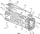
後方の軸受セット12において、調整可能な摺動軸受12a、12b、12cの調整可能性は、後方摺動軸受の調整装置として機能するキャリア17a、17b、17cに一体に設けられたそれぞれの摺動軸受における外側軸受プレート13によってもたらされる。図2にこの構造の一例を示し、キャリア17bは、後方の調整可能な摺動軸受12bから組合さった対の一体の外側軸受プレート13と共に軸受ボックス10の頂壁10bに示されている。内側軸受プレート14は頂壁10bにおける開口18にはめ込まれる。この結果として、内側軸受プレート14は、頂壁10bの平面において軸受ボックス10に対して適切な位置に固定される。この標準の位置では、キャリア17bは頂壁10bに接触し、それで外側軸受プレート13の楔型段部は内側軸受プレート14の受け楔型段部と係合する。一つの実施形態によれば、キャリア17bの前端部には、ネジ付きブッシュ19が設けられている。後方の摺動軸受12bに対する別の調整用ネジ20は端部フランジ16と組合さって着座され、そして軸方向に設けられている。調整用ネジ20はキャリア17bにおけるブッシュ19にねじ込まれる。調整用ネジ20を締付けることによって、キャリア17bは、軸受ボックス10の端部に向かって引張られ、それにより摺動軸受12bにおける軸受プレート13、14は、中間の楔型段部により互いに横方向に離れて引かれ、それにより後方の摺動軸受12bは厚さが増す。このようにして、後方の摺動軸受12bに関する遊びは調整用ネジ20で調整され得る。同様に、軸受ボックスの側部のキャリアは、軸受ボックス10の壁10a、10cにおける後方の摺動軸受12a、12cを調整するように構成されている。図面において、キャリア17a〜17cと一体の外側軸受プレート13は長方形の孔を備えている。これには構造上の効果はないが、外側アーム5と内側アーム6との間の隙間が狭いためになされるだけであり、それにより、図示例では、軸受プレートの楔型端部構造によって、内側軸受プレート14の厚さが最大となる領域において外側軸受プレート13における材料に対する隙間が殆どなくなる。図5a参照。用語別の調整用ネジは、キャリア17bに固定したネジ付きロッドから成る相応した装置を包含しなければならず、その場合にはナットがフランジ16と共にキャリアを軸方向に動かす。この用語はまた軸受プレート13に固定した別のロッドも包含しなければならず、その場合には別の形式の緊締装置がロッドを軸方向に動かす。
In the rear bearing set 12, the
ここで記載したように、全ての調整可能な摺動軸受11a〜11c、12a〜12cの遊びは軸受ボックス10の端部から調整できる。摺動軸受は、摺動軸受の一つの軸受プレートを軸方向に変位させることで調整される。調整用ネジはブーム1の外側アーム5の前方から操作でき、このことは、ブーム1の本体において干渉や処理操作が必要でないことを意味している。それぞれの摺動軸受11a〜11c、12a〜12cにおける軸受プレート13、14は相対的に大きな接触面積で互いに接触するので、摺動軸受は、ブームの外側アーム及び内側アームを介して横方向に伝達される大きな力を吸収できる。これにより、力が調整用ネジで吸収される先行技術の一つの欠点が解消される。
As described herein, the play of all adjustable sliding
摺動軸受を横断面長方形に作ることは共通であり、このことは、摺動軸受が長手方向縁部を備えることを意味している。長手方向縁部は、特に、ホルダーに固定されない摺動軸受の摺動面、例えば外側アーム5の平坦な面に対向する摺動軸受11a〜11c、12a〜12cの面に関連して生じる。摺動軸受を介して大きな力を伝達する必要がある場合には、外側アームに対して回動運動する内側アーム、すなわちブーム1の長手軸線の周りで小さな回転運動を行う内側アーム6に対して縁部が接触する危険があるので、これらの縁部を設けることは適切でないかもしれない。このような縁部接触は摺動軸受を早く磨耗させ得る。
It is common to make the sliding bearing in a rectangular cross section, which means that the sliding bearing comprises a longitudinal edge. The longitudinal edges occur in particular in relation to the sliding surfaces of the sliding bearings not fixed to the holder, for example the surfaces of the sliding
本発明の別の特徴によれば、別の実施形態が提供され、縁部接触は、図6に示すように、摺動軸受の長手方向縁部を面取りすることによって避けられる。この実施形態による面取りは、この場合、ブーム1における外側アーム5に対面する外側軸受プレート13の側面の長手方向縁部において行われる。そして面取りは、摺動軸受の磨耗面が平面でありしかも摺動面の裏側の長手方向縁部が面取りされるように行われる。これは当然逆に行ってもよく、すなわち摺動軸受は平面状の裏面をもち、相応して面取りされかつ摺動軸受に対して動かないアームに固定されるホルダーに接触するようにしてもよい。
According to another feature of the present invention, another embodiment is provided, and edge contact is avoided by chamfering the longitudinal edge of the sliding bearing, as shown in FIG. The chamfering according to this embodiment takes place in this case at the longitudinal edge of the side of the
この実施形態の利点は、摺動軸受と当接する平坦な面との間の圧力分布が一層一様となることにある。別の例は、一つの軸受座の処理表面とブームに関連した摺動軸受の当接する平坦な面の表面とが必ずしも十分に平行である必要がないので、ブームにおけるアームに比較的安価な輪郭(外形)を使用できることにある。 The advantage of this embodiment is that the pressure distribution between the sliding bearing and the flat surface abutting is more uniform. Another example is a relatively inexpensive profile for the arms in the boom, because the processing surface of one bearing seat and the surface of the abutting flat surface of the sliding bearing associated with the boom do not necessarily have to be sufficiently parallel. (Outer shape) can be used.
図6には、上記した摺動軸受11a〜11c、12a〜12c(図面には一つの摺動軸受12bについてのみ示している)の長手方向縁部の面取りの例を示しており、内側アーム6はブーム1に平行である軸線のまわりで回動した状態で示されている。明確にするために、この回動は誇張して示されている。図面には、摺動軸受の長手方向縁部との軸外側アーム5の接触は、摺動軸受の二つの側面間に形成された長手方向縁部において行われることが示されており、当該側面間の角度は90°より非常に大きい鈍角である。内側アーム6は図面にはその頂面6bの形態でのみ示されており、外側アーム5はその頂面5bでのみ示されている。
FIG. 6 shows an example of chamfering of the longitudinal edges of the sliding
Claims (10)
共に方形管構造を形成する四つの壁(10a〜10d)を備えたケーシングとして構成した軸受ボックス(10)を有し、
軸受ボックス(10)が多数の摺動軸受(11a〜11d、12a〜12d)を備え、そして外側アーム(5)と内側アーム(6)との間で外側アーム(5)の前端部内に挿置され、
摺動軸受(11a〜11d、12a〜12d)が、軸受ボックス(10)の壁(10a〜10d)に設けられ、そして外側アーム(5)及び内側アーム(6)の互いに沿ってのびる対応した平坦面に対して適用され、
軸受ボックス(10)の少なくとも一つの壁(10a〜10c)に関して、少なくとも一つの摺動軸受(11a〜11c、12a〜12c)の厚さを調整し従って少なくとも一つの摺動軸受に対して適用した外側アーム(5)と内側アーム(6)との表面間の遊びを調整する軸線方向に装着した調整装置(15、20、17a〜17c)が設けられていること
を特徴とする軸受。An outer arm (5) having a rear end and a front end connected to a carrier (2) of the boom (1), the bearing being incorporated in a telescopic boom (1), and the front end And an inner arm (6) that can be displaced in the axial direction in the outer arm (5). The outer arm (5) and the inner arm (6) are formed of a rectangular tube, and the inner arm (6) is flat. In a bearing whose surface extends along a corresponding flat surface of the outer arm (5) and in which the boom (1) has four longitudinal sides,
A bearing box (10) configured as a casing with four walls (10a to 10d) that together form a rectangular tube structure;
The bearing box (10) comprises a number of sliding bearings (11a-11d, 12a-12d) and is inserted in the front end of the outer arm (5) between the outer arm (5) and the inner arm (6). And
Sliding bearings (11a-11d, 12a-12d) are provided on the walls (10a-10d) of the bearing box (10) and correspondingly flat along the outer arm (5) and the inner arm (6). Applied to the face,
With respect to at least one wall (10a-10c) of the bearing box (10), the thickness of at least one sliding bearing (11a-11c, 12a-12c) is adjusted and thus applied to at least one sliding bearing A bearing comprising an adjusting device (15, 20, 17a to 17c) mounted in an axial direction for adjusting play between surfaces of the outer arm (5) and the inner arm (6).
一緒になって方形管構造を形成する四つの壁(10a〜10d)を備えたケーシングとして軸受ボックス(10)を構成し、
軸受ボックス(10)を外側アーム(5)の前端部内に挿置し、
軸受ボックス(10)の壁(10a〜10d)に摺動軸受(11a〜11d、12a〜12d)を設けて、外側アーム(5)及び内側アーム(6)の互いに沿ってのびる対応した平坦面に対して適用し、
軸受ボックス(10)の少なくとも一つの壁(10a〜10c)に関して、軸線方向に装着した調整装置(15、20、17a〜17c)を設け、
少なくとも一つの摺動軸受(11a〜11c、12a〜12c)の厚さを調整するように調整装置を調整することで、少なくとも一つの摺動軸受(11a〜11c、12a〜12c)と少なくとも一つの摺動軸受に対して適用した外側アーム(5)及び内側アーム(6)の表面と間の軸受遊びを調整すること
を特徴とする軸受遊びの調整方法。An outer arm (5) having a rear end and a front end connected to the carrier (2) of the boom (1), which is incorporated in a telescopic extendable boom (1), and provided at the front end An inner arm (6) that can be displaced axially in the arm (5), the outer arm (5) and the inner arm (6) are formed of a rectangular tube, and the flat surface of the inner arm (6) is the outer arm ( 5) In the adjustment method of the bearing play related to the sliding bearings (11a to 11d, 12a to 12d) extending along the corresponding flat surface,
The bearing box (10) is configured as a casing with four walls (10a to 10d) that together form a rectangular tube structure;
Insert the bearing box (10) into the front end of the outer arm (5),
Sliding bearings (11a to 11d, 12a to 12d) are provided on the walls (10a to 10d) of the bearing box (10) so that the outer arm (5) and the inner arm (6) have corresponding flat surfaces extending along each other. Apply to
With respect to at least one wall (10a to 10c) of the bearing box (10), an adjusting device (15, 20, 17a to 17c) mounted in the axial direction is provided,
By adjusting the adjusting device to adjust the thickness of at least one sliding bearing (11a-11c, 12a-12c), at least one sliding bearing (11a-11c, 12a-12c) and at least one sliding bearing (11a-11c, 12a-12c) A method of adjusting a bearing play, comprising adjusting a bearing play between the outer arm (5) and the inner arm (6) applied to the sliding bearing.
それぞれの摺動軸受における外側軸受プレート(13)と内側軸受プレート(14)との接触面が、互いに係合する段部を備えた相応した楔型段状輪郭をもつように構成され、
一方の形式の軸受プレートが軸受ボックス(10)における座で支持され、
他方の形式の軸受プレートが調整装置と接触し、
調整装置を操作する際に、二つの形式の軸受プレートが互いに軸線方向に変位され、それにより軸受プレートの段状輪郭によって摺動軸受の厚さを変化させ、その結果軸受遊びを変更すること
を特徴とする請求項9記載の軸受遊びの調整方法。The sliding bearings (11a to 11c, 12a to 12c) consist of an outer bearing plate (13), and the outer bearing plate (13) contacts the inner bearing plate (14),
The contact surfaces of the outer bearing plate (13) and the inner bearing plate (14) in each sliding bearing are configured to have a corresponding wedge-shaped stepped profile with steps that engage with each other,
One type of bearing plate is supported by a seat in the bearing box (10),
The other type of bearing plate contacts the adjusting device,
When operating the adjusting device, the two types of bearing plates are displaced axially relative to each other, thereby changing the thickness of the sliding bearing by the stepped profile of the bearing plate and consequently changing the bearing play. 10. The method for adjusting a bearing play according to claim 9, wherein the bearing play is adjusted.
Applications Claiming Priority (3)
| Application Number | Priority Date | Filing Date | Title |
|---|---|---|---|
| SE0502591A SE529341C2 (en) | 2005-11-25 | 2005-11-25 | Storage at the boom for carrying rock drilling equipment |
| SE0502591-1 | 2005-11-25 | ||
| PCT/SE2006/001318 WO2007061358A1 (en) | 2005-11-25 | 2006-11-21 | A bearing in connection with a boom |
Publications (2)
| Publication Number | Publication Date |
|---|---|
| JP2009517568A JP2009517568A (en) | 2009-04-30 |
| JP4945571B2 true JP4945571B2 (en) | 2012-06-06 |
Family
ID=38067478
Family Applications (1)
| Application Number | Title | Priority Date | Filing Date |
|---|---|---|---|
| JP2008542276A Active JP4945571B2 (en) | 2005-11-25 | 2006-11-21 | Bearing built into the boom |
Country Status (8)
| Country | Link |
|---|---|
| EP (1) | EP1951985B1 (en) |
| JP (1) | JP4945571B2 (en) |
| CN (1) | CN101313125B (en) |
| AU (1) | AU2006317734B2 (en) |
| CA (1) | CA2628933C (en) |
| NO (1) | NO338617B1 (en) |
| SE (1) | SE529341C2 (en) |
| WO (1) | WO2007061358A1 (en) |
Families Citing this family (3)
| Publication number | Priority date | Publication date | Assignee | Title |
|---|---|---|---|---|
| DE202010003706U1 (en) * | 2010-03-16 | 2011-09-02 | Dewert Antriebs- Und Systemtechnik Gmbh | Device with at least two relatively movable parts |
| GB2609668B (en) | 2021-08-13 | 2023-09-27 | Caterpillar Inc | Wear pad, telescopic boom assembly and work machine |
| CN116733388A (en) * | 2023-06-12 | 2023-09-12 | 安百拓(南京)建筑矿山设备有限公司 | Engineering machine and adjusting device thereof |
Family Cites Families (5)
| Publication number | Priority date | Publication date | Assignee | Title |
|---|---|---|---|---|
| SE303115B (en) * | 1967-05-24 | 1968-08-19 | Atlas Copco Ab | |
| JPS5872251A (en) * | 1981-10-27 | 1983-04-30 | Mitsubishi Electric Corp | Data processing system |
| FR2535416A1 (en) * | 1982-11-02 | 1984-05-04 | Gouache Ind | Device for guiding and stopping an elongated member which can be moved longitudinally in another elongated member |
| JP3748342B2 (en) * | 1999-10-01 | 2006-02-22 | Tcm株式会社 | Sliding device |
| JP2001295315A (en) * | 2000-04-13 | 2001-10-26 | Hitachi Constr Mach Co Ltd | Bucket |
-
2005
- 2005-11-25 SE SE0502591A patent/SE529341C2/en not_active IP Right Cessation
-
2006
- 2006-11-21 WO PCT/SE2006/001318 patent/WO2007061358A1/en not_active Ceased
- 2006-11-21 CA CA2628933A patent/CA2628933C/en active Active
- 2006-11-21 AU AU2006317734A patent/AU2006317734B2/en active Active
- 2006-11-21 CN CN200680044034.4A patent/CN101313125B/en active Active
- 2006-11-21 EP EP06824463.1A patent/EP1951985B1/en active Active
- 2006-11-21 JP JP2008542276A patent/JP4945571B2/en active Active
-
2008
- 2008-06-12 NO NO20082621A patent/NO338617B1/en unknown
Also Published As
| Publication number | Publication date |
|---|---|
| AU2006317734B2 (en) | 2011-09-08 |
| EP1951985A1 (en) | 2008-08-06 |
| SE529341C2 (en) | 2007-07-10 |
| EP1951985A4 (en) | 2013-01-02 |
| CN101313125B (en) | 2012-11-07 |
| EP1951985B1 (en) | 2014-05-21 |
| JP2009517568A (en) | 2009-04-30 |
| WO2007061358A1 (en) | 2007-05-31 |
| AU2006317734A1 (en) | 2007-05-31 |
| CA2628933A1 (en) | 2007-05-31 |
| CA2628933C (en) | 2014-08-12 |
| CN101313125A (en) | 2008-11-26 |
| NO20082621L (en) | 2008-08-25 |
| NO338617B1 (en) | 2016-09-12 |
| WO2007061358A8 (en) | 2008-07-17 |
| SE0502591L (en) | 2007-05-26 |
Similar Documents
| Publication | Publication Date | Title |
|---|---|---|
| US4906161A (en) | Tiltable bucket assembly | |
| CN101850785B (en) | Steering apparatus | |
| JP2730667B2 (en) | Powerful machine table with quick adjustment | |
| EP1612120A1 (en) | Steering device for motor vehicle | |
| JP4945571B2 (en) | Bearing built into the boom | |
| KR101700203B1 (en) | Roll arrangement | |
| EP4475642B1 (en) | Slide rail assembly | |
| JP4369304B2 (en) | Billet cutting device | |
| US4672831A (en) | Bending press | |
| EP1596006B1 (en) | Extendable paving screed | |
| JPH05505772A (en) | Spherical drilling tool | |
| JP2008265928A (en) | Jib slide pad mounting structure | |
| EP1118722B1 (en) | Work vehicle stabilizing leg. | |
| EP1163144B1 (en) | Tilting device | |
| JP2010535630A (en) | Rolling device with adjusting device | |
| JP4430823B2 (en) | Support roll or intermediate roll used in a rolling mill for rolling flat rolled material | |
| CN212823622U (en) | Inner support device and inner support tool | |
| JP2004034038A (en) | Bending roll | |
| EP4160293A1 (en) | Conical ball cone bearing | |
| KR20010104344A (en) | Quick-coupling assembly | |
| US7497142B2 (en) | Apparatus for the relative adjustment of two parts | |
| JPH10101293A (en) | Slide pad device of boom | |
| JP2826039B2 (en) | Cutting tools | |
| JPH11130377A (en) | Telescopic boom supporting structure for crane | |
| JPH11130378A (en) | Telescopic boom supporting structure for crane |
Legal Events
| Date | Code | Title | Description |
|---|---|---|---|
| A621 | Written request for application examination |
Free format text: JAPANESE INTERMEDIATE CODE: A621 Effective date: 20091023 |
|
| A977 | Report on retrieval |
Free format text: JAPANESE INTERMEDIATE CODE: A971007 Effective date: 20110511 |
|
| A131 | Notification of reasons for refusal |
Free format text: JAPANESE INTERMEDIATE CODE: A131 Effective date: 20110518 |
|
| A521 | Request for written amendment filed |
Free format text: JAPANESE INTERMEDIATE CODE: A523 Effective date: 20110817 |
|
| TRDD | Decision of grant or rejection written | ||
| A01 | Written decision to grant a patent or to grant a registration (utility model) |
Free format text: JAPANESE INTERMEDIATE CODE: A01 Effective date: 20120208 |
|
| A01 | Written decision to grant a patent or to grant a registration (utility model) |
Free format text: JAPANESE INTERMEDIATE CODE: A01 |
|
| A61 | First payment of annual fees (during grant procedure) |
Free format text: JAPANESE INTERMEDIATE CODE: A61 Effective date: 20120305 |
|
| R150 | Certificate of patent or registration of utility model |
Free format text: JAPANESE INTERMEDIATE CODE: R150 Ref document number: 4945571 Country of ref document: JP Free format text: JAPANESE INTERMEDIATE CODE: R150 |
|
| FPAY | Renewal fee payment (event date is renewal date of database) |
Free format text: PAYMENT UNTIL: 20150309 Year of fee payment: 3 |
|
| R250 | Receipt of annual fees |
Free format text: JAPANESE INTERMEDIATE CODE: R250 |
|
| R250 | Receipt of annual fees |
Free format text: JAPANESE INTERMEDIATE CODE: R250 |
|
| R250 | Receipt of annual fees |
Free format text: JAPANESE INTERMEDIATE CODE: R250 |
|
| R250 | Receipt of annual fees |
Free format text: JAPANESE INTERMEDIATE CODE: R250 |
|
| S533 | Written request for registration of change of name |
Free format text: JAPANESE INTERMEDIATE CODE: R313533 |
|
| R350 | Written notification of registration of transfer |
Free format text: JAPANESE INTERMEDIATE CODE: R350 |
|
| R250 | Receipt of annual fees |
Free format text: JAPANESE INTERMEDIATE CODE: R250 |
|
| R250 | Receipt of annual fees |
Free format text: JAPANESE INTERMEDIATE CODE: R250 |
|
| R250 | Receipt of annual fees |
Free format text: JAPANESE INTERMEDIATE CODE: R250 |
|
| R250 | Receipt of annual fees |
Free format text: JAPANESE INTERMEDIATE CODE: R250 |
|
| R250 | Receipt of annual fees |
Free format text: JAPANESE INTERMEDIATE CODE: R250 |
|
| R250 | Receipt of annual fees |
Free format text: JAPANESE INTERMEDIATE CODE: R250 |
|
| R250 | Receipt of annual fees |
Free format text: JAPANESE INTERMEDIATE CODE: R250 |