JP4853059B2 - Car side structure - Google Patents
Car side structure Download PDFInfo
- Publication number
- JP4853059B2 JP4853059B2 JP2006064784A JP2006064784A JP4853059B2 JP 4853059 B2 JP4853059 B2 JP 4853059B2 JP 2006064784 A JP2006064784 A JP 2006064784A JP 2006064784 A JP2006064784 A JP 2006064784A JP 4853059 B2 JP4853059 B2 JP 4853059B2
- Authority
- JP
- Japan
- Prior art keywords
- door
- airbag
- occupant
- seat
- vehicle
- Prior art date
- Legal status (The legal status is an assumption and is not a legal conclusion. Google has not performed a legal analysis and makes no representation as to the accuracy of the status listed.)
- Expired - Fee Related
Links
Images


Landscapes
- Air Bags (AREA)
Description
本発明は、サイドドアにエアバッグ装置を配置して、側面衝突時の乗員への影響を緩和する自動車の側部構造に関する。 The present invention relates to a side structure of an automobile in which an air bag device is arranged on a side door to alleviate the influence on a passenger at the time of a side collision.
従来の構造として、特許文献1には、サイドドア内部にエアバッグ装置を配置し、エアバッグがドアトリムのアームレスト部上方に展開する構造が記載されている。また、特許文献2には、エアバッグ装置をサイドドア内部であってドアトリムの車外側に配置し、エアバッグを車室内側に展開させる構造が記載されている。
上記従来の構造は、エアバッグを乗員の側部、または上方に向けて展開させることで、側面衝突時に車外側に傾動する乗員の上半身を支えるものであり、乗員の下半身である腰部の保護を目的としたものではない。 The conventional structure supports the upper body of the occupant that tilts to the outside of the vehicle during a side collision by deploying the airbag toward the occupant's side or upward, and protects the lower back, which is the lower body of the occupant. It is not intended.
さらに、従来の構造として、図6(a)に示すように、サイドドア101内部における乗員の腰部近傍に衝撃吸収パッド102を配設した構造がある。しかし、この構造では、衝撃吸収パッド102がアームレスト部103下方に配置されるため、その配置スペース分だけドアポケット104の容積を縮小せざるを得ないという不都合がある。
Furthermore , as a conventional structure, as shown in FIG. 6A, there is a structure in which an
本発明は、上述の課題に鑑みてなされ、その目的は、側面衝突時にエアバッグを乗員の腰部に向けて展開させ、側面衝突時にサイドドアが車室内側へ変位することによる乗員への影響を緩和する自動車の側部構造を提供することである。 The present invention has been made in view of the above-mentioned problems, and its purpose is to develop an airbag toward the occupant's waist during a side collision, and to influence the occupant due to the side door being displaced toward the vehicle interior during a side collision. It is to provide a side structure of the automobile to be mitigated.
この発明の自動車の側部構造は、車室内側に膨出するアームレスト部が形成されたドアトリムを有するサイドドアと、車体側面視で前記サイドドアと重複する位置に配置された座席とを備え、前記サイドドア内部にエアバッグ装置が配置された自動車の側部構造であって、前記エアバッグ装置を前記ドアトリムにおける前記アームレスト部を形成する膨出空間に収容すると共に、エアバッグが前記アームレスト部下方の前記ドアトリムと前記座席との間に向けて展開するように配設され、前記アームレスト部の下方にはドアポケットが形成され、前記エアバッグは、アームレスト部の下部とドアポケットの上部との間を埋めるように、かつ、乗員の腰部に向けて展開するように構成されたものである。 The side part structure of the automobile of the present invention includes a side door having a door trim formed with an armrest portion that bulges toward the vehicle interior side, and a seat disposed at a position overlapping the side door in a side view of the vehicle body, A side part structure of an automobile in which an airbag device is disposed inside the side door, wherein the airbag device is housed in an inflated space forming the armrest portion in the door trim, and an airbag is located below the armrest portion. The door trim is disposed between the door trim and the seat, a door pocket is formed below the armrest portion, and the airbag is disposed between the lower portion of the armrest portion and the upper portion of the door pocket. It is comprised so that it may expand | deploy toward a passenger | crew's waist | hip | lumbar part.
上記構成によれば、側面衝突時にエアバッグを乗員の腰部に向けて展開させることで、側面衝突時にサイドドアが車室内側へ変位することによる乗員への影響を緩和することができる。 According to the above configuration, by deploying the airbag toward the occupant's waist during a side collision, the influence on the occupant due to the side door being displaced toward the passenger compartment during the side collision can be mitigated.
この発明の一実施態様においては、前記エアバッグ装置は、車体側面視で前記エアバッグが前記アームレスト部下方に設けられたドアポケットと重複する位置に展開するように配設されているものである。
従来の構造では、アームレスト部は車内側に膨出している分、乗員に早期に当接し付勢することになるが、収納性を良くするために設けられるドアポケットは中空のため、乗員の腰部を早期に付勢することができない。これに対して、この実施形態よれば、ドアポケット付近にエアバッグが展開するため、ドアポケットの存在にかかわらず乗員への衝突エネルギーを早期に緩和することができる。
According to another embodiment of the present invention, the airbag apparatus is that the air bag when the body is viewed from the side is arranged so as to be deployed at a position that overlaps with the door pocket provided below the armrest .
In the conventional structure, the armrest part bulges toward the inside of the car, so it quickly abuts and urges the occupant, but the door pocket provided for better storage is hollow, so the lumbar part of the occupant Cannot be energized early. In contrast, according to this embodiment, since the air bag in the vicinity of the door pocket is deployed, Ru can be relaxed collision energy to the occupant regardless of the presence of the door pocket early.
本発明によれば、側面衝突時にエアバッグを乗員の腰部に向けて展開させ、側面衝突時にサイドドアが車室内側へ変位することによる乗員への影響を緩和することができる効果がある。 According to the present invention, to expand toward the air bag to the occupant's waist during a side collision, the side door during a side collision the effect that can and Turkey to mitigate the effects of the occupant by being displaced toward the vehicle interior side .
本発明の一実施形態を、以下図面に基づいて詳細に説明する。 This onset bright one real 施形 condition, will be described in detail with reference to the accompanying drawings.
なお、以下に説明する実施の形態は、本発明の実現手段としての一例であり、本発明は、その趣旨を逸脱しない範囲で下記実施形態を修正、または変形したものに適用可能である。 Incidentally, the embodiments described below are examples as implementation means of the present invention, the present invention may modify the following embodiments within a scope not departing from the spirit, or Ru applicable der in a modification .
[第1の実施形態]
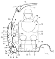
図1は、本発明に係る第1の実施形態の自動車の側部構造としてフロントサイドドア内部および車室内を透視して示す車幅方向から見た側面図である。図2は、第1の実施形態の自動車の側部構造としてフロントサイドドア内部および車室内を車体前方から見た断面図である。図3は、本実施形態のフロントサイドドアを車室内側から見た側面図である。図4は、図3のA−A断面図である。
[First Embodiment]
Figure 1 is a side view from the first front side door interior Oyo vehicle width direction indicated by fluoroscopy beauty passenger compartment as automobile side structure of the embodiment of the present invention. Figure 2 is a cross-sectional view of the front side door interior and passenger compartment from the front of the vehicle body as a vehicle side structure of the first embodiment. FIG. 3 is a side view of the front side door of the present embodiment as viewed from the vehicle interior side. 4 is a cross-sectional view taken along line AA in FIG.
図1乃至図4に示すように、車体側部には、センタピラー3を挟んで車体前方側および後方側のそれぞれに、車室内外を連通するようにフロント開口部1Fおよびリヤ開口部1Rが形成されている。
As shown in FIGS. 1 to 4, the vehicle body side portion, each of the vehicle body front side and the rear side across the sensor Tapi Ra 3, the front opening 1F so as to communicate the vehicle interior outside and A
フロント開口部1Fは、前縁部がフロントピラー2、後縁部がセンタピラー3、上縁部がルーフサイドレール4、下縁部がサイドシル5で画定されている。また、リヤ開口部1Rは、前縁部がセンタピラー3、後縁部がリヤピラー(不図示)、上縁部がルーフサイドレール4、下縁部がサイドシル5で画定されている。なお、センタピラーがない車体構造もある。
The front opening. 1F, leading edge front pillar 2, a rear edge sensor Tapi color 3, the upper edge is roof side rail 4, the lower edge is defined by the
フロント開口部1Fの前縁部には、略水平に回動して当該フロント開口部1Fを開閉するように、ヒンジを介してフロントサイドドア6の前端部が結合されている。 The front edge of the front opening 1F, to open and close the front opening 1F rotates approximately horizontally, the front end of the front rhino de door 6 is coupled via a hinge.
サイドシル5は、車室内の床面を構成するフロアパネル7の車幅方向の側縁部に沿って車体前後方向に延びている。
The
また、サイドシル5の表面は、乗降時の乗員の靴底による擦れ等から保護するカバー部材5dおよびスカッフプレート8で覆われている。カバー部材5dおよびスカッフプレート8は、クリップ等によりサイドシル5の表面に取り付けられている。
The surface of the
また、ルーフサイドレール4は車室内の天井部分を構成するルーフパネル9の側縁部に沿って車体前後方向に延びている。また、センタピラー3にはシートベルト10およびベルト巻取り機構(不図示)が配設される。
Further, the roof side rail 4 extends in the longitudinal direction of the vehicle body along the side edge portion of the roof panel 9 constituting the ceiling portion in the vehicle interior. Further, the sensor Tapi Ra 3
ルーフサイドレール4は、鋼材からなるアウタパネルおよびインナパネルの各側縁のフランジ部を接合して所望の強度を確保した閉断面部材を構成している。 Roof side rail 4, by joining the flange portion of each side edge of the outer panel and an inner panel made of steel constitutes a closed-section member secured to desired strength.
サイドシル5は、鋼材からなるサイドシルアウタパネル5a、サイドシルインナパネル5bおよび両パネル間に配設される補強鋼板5cの上下のフランジ部を接合して所望の強度を確保した閉断面部材を構成している。
フロアパネル7の車室内側表面には、遮音効果のある布製のフロアマット11が敷き詰められている。また、ルーフパネル9の車室内側表面は防音効果のある樹脂製のトップシーリング12で覆われている。
The vehicle interior side surface of the
また、フロアパネル7上には、フロントサイドドア6の閉成状態で該フロントサイドドア6の車室内側面(ドアトリム)に近接し、車幅方向から見て(車体側面視で)フロントサイドドア6と重複する位置にフロントシート13が配置されている。
Also, on the
フロントシート13は、フロアパネル7から突出して形成されたシートマウント14に取り付けられるシートレール15と、スライドレバー16aによりシートレール15にスライド可能に保持されて乗員Hが着座するシートクッション16と、リクライニングレバー17aによりシートクッション16後端部に車体前後方向に傾動(リクライニング)可能に軸支された背もたれ部17と、背もたれ部17の上端部に配設されるヘッドレスト18と、を有する。
本実施形態の車体側部構造は、フロアパネル7の車幅方向の中央部Lを中心として略対称に構成されており、互いに隣接して運転席および助手席となるフロントシート13が配設される。
The vehicle body side portion structure of this embodiment is constructed substantially symmetrically about a central portion L in the vehicle width direction of the
車室内のフロントシート13前方には、計器類やスイッチ類が配置されるインストルメントパネル19やステアリングハンドル20、足元にはペダル類21が配設されている。
In front of the
また、図4に示すように、フロントサイドドア6内部におけるドアインナパネル32とドアトリム33の間にはエアバッグ装置22が配設されている。エアバッグ装置22は、折り畳んで格納されるエアバッグ23と、エアバッグ23を展開させる起爆剤としてのインフレータ24とを備える。
As shown in FIG. 4, an
なお、エアバッグ装置は、運転席前方のステアリングホイール中央部や、助手席前方のコンソールボックス内にも配設されている。 The airbag device is also disposed in the center of the steering wheel in front of the driver's seat and in the console box in front of the passenger seat.
<ドアの内部構造>
フロントサイドドア6は、車幅方向に沿って、最も外側に位置するドアアウタパネル31と、ドアアウタパネル31より車室内側に位置するドアインナパネル32と、ドアインナパネル32の車室内側を覆うドアトリム33と、で構成される。
<Door internal structure>
The front side door 6 includes a door
ドアアウタパネル31およびドアインナパネル32は鋼板からなり、両パネル31,32の間に空間を形成するように互いの側縁部および下縁部が溶接等で接合され、上縁部にはドアガラス25が昇降可能にスリット状の開口部が形成されている。
The door
ドアアウタパネル31の車室内側表面には、図2に示すように、鉛直方向の略中央付近で車体前後方向に延びる補強鋼材34が溶接等で接合され、さらに、この補強鋼材34の下方には車体前後方向に延びるインパクトバー35が溶接等で接合されている。インパクトバー35は補強鋼材34と共に、側面衝突時等においてフロントサイドドア6に印加される衝撃を受容する機能を有する。
The vehicle interior side surface of the door
ドアアウタパネル31には、車外からフロントサイドドア6の開閉操作を行うドアアウタハンドル36が配設されている。
The door
ドアインナパネル32は、その上端部32aおよび下端部32bが所定の強度を有する鋼材で構成され、これら上端部32aおよび下端部32bを外枠部として樹脂製のパネル部材32cをボルト等で連結した、所謂ドアモジュールとして構成されている。なお、ドアインナパネル32を全て鋼材で構成してもよいが、ドアインナパネル32をドアモジュールとして構成すると、ドアトリム33との間に配設される部品のレイアウトに応じてパネル部材32cの形状のみを決定し成形できるという利点がある。
Door
ドアトリム33は樹脂製であり、車室内の内装材の一部を構成している。ドアアウタパネル31とドアインナパネル32との間の空間にはドアガラス25やドアガラス25を昇降させるウインドレギュレータ26等が配設される。
The
ドアトリム33の車室内側表面には、車内からフロントサイドドア6の開閉操作を行うドアインナハンドル27やドアロック(不図示)、アームレスト部33aが設けられている。
A door
アームレスト部33aは、車室内側に膨出するようにドアトリム33の鉛直方向の略中央付近で車体前後方向に延びている。さらに、ドアトリム33のアームレスト部33aの後下方には車室内側に膨出して収納用の空間部を形成するドアポケット33bが形成されている。さらに、ドアポケット33の前方にはドアトリムにスピーカを取り付けるための円形のスピーカグリル33cが配設されている。
The
エアバッグ装置22は、図4に示すように、ドアトリム33におけるアームレスト部33aを形成する膨出空間に収容されブラケット22aを介して取り付けられており、側面衝突時のように車体に所定の加速度が加わった時にインフレータ24が作動し、エアバッグ23がアームレスト部33a下方であってドアトリム33とフロントシート13のシートクッション部16との間に向けて展開する。換言すると、エアバッグ装置22は、車幅方向から見てエアバッグ23がアームレスト部33a下方に設けられたドアポケット33bと重複する位置に展開するように配設されている。
As shown in FIG. 4 , the
さらに、アームレスト部33aには、エアバッグ23展開時に該エアバッグ23が展開しやすいように途中で破断し開口するドア部33dが形成されている。なお、ドア部33dは、アームレスト部33aにおけるエアバッグ23が展開する部位に溝状の切り込みを入れる等して部分的に肉厚を小さく脆弱に形成してもよい。
In addition, the
上記実施形態によれば、側面衝突時にエアバッグ23が乗員Hの腰部に向けて展開し車室内側に付勢するので、衝突時の衝撃でフロントサイドドア6が車室内側へ変位することによる乗員Hへの影響を緩和することができる。
According to the above-described embodiment, the
また、ドアポケット33b付近にエアバッグ23が展開するため、ドアポケット33bの存在にかかわらず乗員Hへの衝撃を早期に緩和することができる。
In addition, since the
また、図6(b)に示すように、ドアポケット33bの容積を縮小することもなくなる。
Further, as shown in FIG. 6B, the volume of the
[参考例]
図5は、参考例のフロントサイドドア内部の断面図であり、エアバッグ43の未展開時(a)およびエアバッグ展開時(b)の状態をそれぞれ示している。なお、以下では、第1の実施形態と同一の要素には同一の符号を付してその詳しい説明を省略する。
[ Reference example ]
Figure 5 is a cross-sectional view of the interior front side door of Reference Example, respectively show a state when non-deployed airbag 43 (a) and when the air bag deployment (b). In the following, the same elements as those in the first embodiment are denoted by the same reference numerals, and detailed description thereof is omitted.
この参考例は、エアバッグ装置42を、サイドドア6内部のドアインナパネル32に取り付け、エアバッグ43がドアトリム33とドアインナパネル32との間の空間で展開することで、ドアトリム33が車室内側に変位するように構成したものである。さらに詳しくは、エアバッグ装置42は、エアバッグ43の展開によりアームレスト部33a後下方のドアポケット33b付近のドアトリム33を車室内側に変位させるように配設されている。44はインフレータである。
In this reference example , the
この参考例によれば、エアバッグ43の展開によりドアトリム33を介して乗員の腰部を早期に車室内側に付勢するので、側面衝突時にサイドドア6が車室内側へ変位することによる乗員への影響を緩和することができる。特に、エアバッグ43が乗員に直接当接するのではなく、ドアトリム33を介して乗員を付勢するため、エアバッグ展開時の摩擦等による挙動変化の影響にかかわらず、乗員の腰部の付勢を確実に行うことができる。さらに、ドアポケット33bを衝撃に対する緩衝材としても利用できる。
According to this reference example , because the
なお、本実施形態では運転席や助手席のフロントサイドドア内部にエアバッグ装置を配置した構成について説明したが、後部座席のリヤサイドドアにエアバッグ装置を配置した場合でも適用可能である。 In the present embodiment, the configuration in which the airbag device is arranged inside the front side door of the driver's seat or the passenger's seat has been described. However, the present invention can be applied even when the airbag device is arranged in the rear side door of the rear seat.
6 フロントサイドドア(サイドドア)
13 フロントシート(座席)
22 エアバッグ装置
23 エアバッグ
33 ドアトリム
33a アームレスト部
33b ドアポケット
6 Front side door (side door)
13 front seat (seat)
22 airbag device
23
33a Armrest part
33b Door pocket
Claims (2)
車体側面視で前記サイドドアと重複する位置に配置された座席とを備え、
前記サイドドア内部にエアバッグ装置が配置された自動車の側部構造であって、
前記エアバッグ装置を前記ドアトリムにおける前記アームレスト部を形成する膨出空間に収容すると共に、
エアバッグが前記アームレスト部下方の前記ドアトリムと前記座席との間に向けて展開するように配設され、
前記アームレスト部の下方にはドアポケットが形成され、
前記エアバッグは、アームレスト部の下部とドアポケットの上部との間を埋めるように、かつ、乗員の腰部に向けて展開するように構成された
ことを特徴とする自動車の側部構造。 A side door having a door trim formed with an armrest portion that bulges toward the vehicle interior;
A seat arranged at a position overlapping with the side door in a side view of the vehicle body,
A side part structure of an automobile in which an airbag device is arranged inside the side door,
While accommodating the airbag device in the bulging space forming the armrest portion in the door trim,
An airbag is disposed so as to deploy between the door trim and the seat below the armrest portion ;
A door pocket is formed below the armrest portion,
The side portion of an automobile, wherein the airbag is configured to be embedded between a lower portion of an armrest portion and an upper portion of a door pocket and to be deployed toward an occupant's waist. Construction.
Priority Applications (1)
| Application Number | Priority Date | Filing Date | Title |
|---|---|---|---|
| JP2006064784A JP4853059B2 (en) | 2006-03-09 | 2006-03-09 | Car side structure |
Applications Claiming Priority (1)
| Application Number | Priority Date | Filing Date | Title |
|---|---|---|---|
| JP2006064784A JP4853059B2 (en) | 2006-03-09 | 2006-03-09 | Car side structure |
Publications (2)
| Publication Number | Publication Date |
|---|---|
| JP2007237983A JP2007237983A (en) | 2007-09-20 |
| JP4853059B2 true JP4853059B2 (en) | 2012-01-11 |
Family
ID=38583927
Family Applications (1)
| Application Number | Title | Priority Date | Filing Date |
|---|---|---|---|
| JP2006064784A Expired - Fee Related JP4853059B2 (en) | 2006-03-09 | 2006-03-09 | Car side structure |
Country Status (1)
| Country | Link |
|---|---|
| JP (1) | JP4853059B2 (en) |
Families Citing this family (5)
| Publication number | Priority date | Publication date | Assignee | Title |
|---|---|---|---|---|
| KR100945075B1 (en) | 2008-05-19 | 2010-03-05 | 한일이화주식회사 | Car door armrest with air bag. |
| JP2010195124A (en) * | 2009-02-24 | 2010-09-09 | Mazda Motor Corp | Occupant protection device for vehicle |
| JP5381200B2 (en) * | 2009-03-18 | 2014-01-08 | マツダ株式会社 | Vehicle occupant protection device |
| JP2015047876A (en) * | 2013-08-29 | 2015-03-16 | 三菱自動車工業株式会社 | Automobile front door structure |
| CN113232607B (en) * | 2021-05-28 | 2023-01-31 | 一汽奔腾轿车有限公司 | Multi-functional automobile door protective plate handrail tilting mechanism |
Family Cites Families (5)
| Publication number | Priority date | Publication date | Assignee | Title |
|---|---|---|---|---|
| JP2895577B2 (en) * | 1990-06-13 | 1999-05-24 | マツダ株式会社 | Energy absorption device on the side of the vehicle |
| JP2921996B2 (en) * | 1991-01-31 | 1999-07-19 | マツダ株式会社 | Energy absorption structure on the side of the vehicle |
| JPH1128998A (en) * | 1997-05-16 | 1999-02-02 | Tokai Rika Co Ltd | Occupant protecting device for vehicle |
| JP2007015467A (en) * | 2005-07-05 | 2007-01-25 | Toyoda Gosei Co Ltd | Occupant crash protection device |
| JP2007022269A (en) * | 2005-07-14 | 2007-02-01 | Toyoda Gosei Co Ltd | Protective bag |
-
2006
- 2006-03-09 JP JP2006064784A patent/JP4853059B2/en not_active Expired - Fee Related
Also Published As
| Publication number | Publication date |
|---|---|
| JP2007237983A (en) | 2007-09-20 |
Similar Documents
| Publication | Publication Date | Title |
|---|---|---|
| JP3595998B2 (en) | Vehicle side airbag device | |
| CN105073510B (en) | Built-in side air bag it is vehicle seat used | |
| JP6156279B2 (en) | Rear seat airbag device for vehicle | |
| JPH08175311A (en) | Inflatable type restraint device in car | |
| WO2012053082A1 (en) | Side airbag device for rear seat | |
| JP3595997B2 (en) | Side airbag device for pillarless vehicles | |
| JP3951848B2 (en) | Rear occupant protection device in vehicle | |
| JP2011051513A (en) | Airbag arrangement structure for vehicle | |
| US6152482A (en) | Vehicle inflatable restraint system trim with trim deploying module | |
| JP2966023B2 (en) | Energy absorption structure on the side of the vehicle | |
| JP4946664B2 (en) | Airbag device | |
| JP2010115960A (en) | Airbag device between vehicle seats | |
| JP2005519799A (en) | Crew restraint system placed in the rear passenger compartment of a car | |
| JP4518468B2 (en) | Automobile with body structure and side collision protection device | |
| JP3988566B2 (en) | Air bag device for rear impact | |
| JP4853059B2 (en) | Car side structure | |
| JP2577405Y2 (en) | Automotive airbag equipment | |
| JP2000025552A (en) | Shock protective device | |
| JPH09188215A (en) | Side collision protection system for automobiles | |
| JP4725372B2 (en) | Car side structure | |
| JP5217210B2 (en) | Vehicle harness arrangement structure | |
| JP4811169B2 (en) | Body structure | |
| JP7246614B2 (en) | vehicle interior structure | |
| JP3712081B2 (en) | Vehicle airbag device | |
| JP2010188767A (en) | Occupant protection device, and vehicle |
Legal Events
| Date | Code | Title | Description |
|---|---|---|---|
| A621 | Written request for application examination |
Free format text: JAPANESE INTERMEDIATE CODE: A621 Effective date: 20081226 |
|
| RD03 | Notification of appointment of power of attorney |
Free format text: JAPANESE INTERMEDIATE CODE: A7423 Effective date: 20101001 |
|
| RD04 | Notification of resignation of power of attorney |
Free format text: JAPANESE INTERMEDIATE CODE: A7424 Effective date: 20101101 |
|
| A131 | Notification of reasons for refusal |
Free format text: JAPANESE INTERMEDIATE CODE: A131 Effective date: 20101214 |
|
| A977 | Report on retrieval |
Free format text: JAPANESE INTERMEDIATE CODE: A971007 Effective date: 20101216 |
|
| A521 | Written amendment |
Free format text: JAPANESE INTERMEDIATE CODE: A523 Effective date: 20110210 |
|
| TRDD | Decision of grant or rejection written | ||
| A01 | Written decision to grant a patent or to grant a registration (utility model) |
Free format text: JAPANESE INTERMEDIATE CODE: A01 Effective date: 20110927 |
|
| A01 | Written decision to grant a patent or to grant a registration (utility model) |
Free format text: JAPANESE INTERMEDIATE CODE: A01 |
|
| A61 | First payment of annual fees (during grant procedure) |
Free format text: JAPANESE INTERMEDIATE CODE: A61 Effective date: 20111010 |
|
| FPAY | Renewal fee payment (event date is renewal date of database) |
Free format text: PAYMENT UNTIL: 20141104 Year of fee payment: 3 |
|
| R150 | Certificate of patent or registration of utility model |
Ref document number: 4853059 Country of ref document: JP Free format text: JAPANESE INTERMEDIATE CODE: R150 Free format text: JAPANESE INTERMEDIATE CODE: R150 |
|
| LAPS | Cancellation because of no payment of annual fees |