JP4846646B2 - Contactless power supply - Google Patents
Contactless power supply Download PDFInfo
- Publication number
- JP4846646B2 JP4846646B2 JP2007099586A JP2007099586A JP4846646B2 JP 4846646 B2 JP4846646 B2 JP 4846646B2 JP 2007099586 A JP2007099586 A JP 2007099586A JP 2007099586 A JP2007099586 A JP 2007099586A JP 4846646 B2 JP4846646 B2 JP 4846646B2
- Authority
- JP
- Japan
- Prior art keywords
- circuit
- power
- receiving coil
- power receiving
- resonance
- Prior art date
- Legal status (The legal status is an assumption and is not a legal conclusion. Google has not performed a legal analysis and makes no representation as to the accuracy of the status listed.)
- Expired - Fee Related
Links
Images


Classifications
-
- Y—GENERAL TAGGING OF NEW TECHNOLOGICAL DEVELOPMENTS; GENERAL TAGGING OF CROSS-SECTIONAL TECHNOLOGIES SPANNING OVER SEVERAL SECTIONS OF THE IPC; TECHNICAL SUBJECTS COVERED BY FORMER USPC CROSS-REFERENCE ART COLLECTIONS [XRACs] AND DIGESTS
- Y02—TECHNOLOGIES OR APPLICATIONS FOR MITIGATION OR ADAPTATION AGAINST CLIMATE CHANGE
- Y02T—CLIMATE CHANGE MITIGATION TECHNOLOGIES RELATED TO TRANSPORTATION
- Y02T10/00—Road transport of goods or passengers
- Y02T10/60—Other road transportation technologies with climate change mitigation effect
- Y02T10/72—Electric energy management in electromobility
Landscapes
- Current-Collector Devices For Electrically Propelled Vehicles (AREA)
Description
本発明は、非接触給電装置に関し、特に、給電装置の能力内で負荷を平準化し、受電部分の小型化や地上給電設備容量の低減、あるいは給電区間長の増大を図るようにした非接触給電装置に関するものである。 The present invention relates to a non-contact power feeding device, and in particular, a non-contact power feeding in which the load is leveled within the capability of the power feeding device, the power receiving part is downsized, the ground power supply equipment capacity is reduced, or the power feeding section length is increased. It relates to the device.
非接触給電装置の受電回路の出力は、負荷電力が増大するに従い電圧が低下する特性を有する。
これは、1次給電線と2次側の受電コイルの間の漏洩磁束による磁気結合の効率低下により、2次側受電コイルのインピーダンスが発生するからである。
受電コイルと給電線の位置関係、コイルの温度、製作寸法の誤差などの要因により、複数の受電回路を結合して出力電力を増大させる場合、受電コイルの電源インピーダンスの小さい受電コイルに負荷が集中するため、受電コイル間に負荷に供給する電力のアンバランスが生じる。
負荷が集中した回路では、発熱の増大やフューズ溶断、故障率の増加などの弊害が生じるため、負荷を平準化する方が好ましい。
The output of the power receiving circuit of the non-contact power feeding device has a characteristic that the voltage decreases as the load power increases.
This is because the impedance of the secondary power receiving coil is generated due to a decrease in the efficiency of magnetic coupling due to the leakage magnetic flux between the primary power supply line and the secondary power receiving coil.
When the output power is increased by combining multiple power receiving circuits due to factors such as the positional relationship between the power receiving coil and the power supply line, coil temperature, and manufacturing dimension errors, the load is concentrated on the power receiving coil with a small power supply impedance. Therefore, an imbalance of power supplied to the load occurs between the power receiving coils.
In a circuit in which the load is concentrated, adverse effects such as an increase in heat generation, fuse blowing, and an increase in failure rate occur. Therefore, it is preferable to level the load.
また、受電コイルと負荷を直列に接続し、受電コイルと負荷の間に共振コンデンサを接続する直列共振回路にコンデンサ入力型の整流回路を接続した場合、平滑コンデンサの静電容量が大きいと2次コイルに誘起する電圧のピーク近傍でしか負荷電流が共振回路に流れない。
この電流の周波数は励磁電流の周波数の3倍、5倍、7倍、更に高次の高調波電流成分を持つが、この高調波電流は、直列共振回路の共振周波数以外の周波数ではインピーダンスが高くなる帯域通過フィルタとして作用するため、受電コイルの能力を有効に利用できず、並列共振型の受電回路に対して取り出し得る出力電力が小さくなる欠点がある。
In addition, when a capacitor input type rectifier circuit is connected to a series resonant circuit in which a power receiving coil and a load are connected in series and a resonant capacitor is connected between the power receiving coil and the load, if the capacitance of the smoothing capacitor is large, the secondary The load current flows through the resonance circuit only near the peak of the voltage induced in the coil.
The frequency of this current is three times, five times, seven times the frequency of the excitation current, and higher harmonic current components, but this harmonic current has high impedance at frequencies other than the resonance frequency of the series resonance circuit. Therefore, there is a drawback that the power of the power receiving coil cannot be used effectively, and the output power that can be extracted from the parallel resonance type power receiving circuit is reduced.
本発明は、上記従来の非接触給電装置が有する問題点に鑑み、各受電コイルの状態が異なっていても負荷を平準化することができる非接触給電装置を提供することを第1の目的とし、また、高調波電流をバイパスさせることにより効率よく負荷に電力を供給することを第2の目的とする。 The present invention has as its first object to provide a non-contact power feeding device capable of leveling a load even if the state of each power receiving coil is different in view of the problems of the conventional non-contact power feeding device. A second object is to efficiently supply power to the load by bypassing the harmonic current.
上記目的を達成するため、本発明の非接触給電装置は、複数の受電コイルを有するとともに、受電コイル毎に共振回路、整流回路及び電圧安定化回路を有し、各電圧安定化回路の出力を結合するようにした非接触給電装置において、電圧安定化回路に、一定の出力電流以上で電圧が出力電流に比例して下がる垂下特性を持たせるとともに、各受電コイルの共振回路に、整流回路と並列に高調波バイパスコンデンサを接続したことを特徴とする。 In order to achieve the above object, a non-contact power feeding device of the present invention has a plurality of power receiving coils, a resonance circuit, a rectifier circuit, and a voltage stabilizing circuit for each power receiving coil, and outputs each voltage stabilizing circuit. in the non-contact power feeding apparatus that bind, to a voltage stabilizing circuit, Rutotomoni, the resonant circuit of each receiving coil to have a drooping characteristic which decreases in proportion to the constant output current or voltage in the output current, the rectifier circuit And a harmonic bypass capacitor connected in parallel .
本発明の非接触給電装置によれば、複数の受電コイルを有するとともに、受電コイル毎に共振回路、整流回路及び電圧安定化回路を有し、各電圧安定化回路の出力を結合するようにした非接触給電装置において、電圧安定化回路に、一定の出力電流以上で電圧が出力電流に比例して下がる垂下特性を持たせることから、各受電コイルから受電する電力を平準化することができ、これにより、一部の回路への負荷の集中を防止し、発熱の増大やフューズ溶断、故障率の増加等の弊害を防止することができる。 According to the non-contact power feeding device of the present invention, the power receiving coil has a plurality of power receiving coils, and each power receiving coil has a resonance circuit, a rectifier circuit, and a voltage stabilizing circuit, and combines outputs of the voltage stabilizing circuits. In the non-contact power supply device, the voltage stabilizing circuit has a drooping characteristic in which the voltage drops in proportion to the output current at a certain output current or more, so that the power received from each receiving coil can be leveled. As a result, it is possible to prevent the concentration of the load on a part of the circuits and to prevent adverse effects such as an increase in heat generation, a fuse blown, and an increase in failure rate.
特に、各受電コイルの共振回路に、整流回路と並列に高調波バイパスコンデンサを接続することにより、整流回路に流れる高調波電流に対して共振回路に流れる基本波電流を増加し、給電電力を安定させることができる。 In particular , by connecting a harmonic bypass capacitor in parallel to the rectifier circuit to the resonance circuit of each power receiving coil, the fundamental current flowing in the resonance circuit is increased relative to the harmonic current flowing in the rectifier circuit, thereby stabilizing the feed power Can be made.
以下、本発明の非接触給電装置の実施の形態を、図面に基づいて説明する。 Hereinafter, embodiments of the non-contact power feeding device of the present invention will be described with reference to the drawings.
図1に、非接触給電装置の受電コイルの構造を示す。
給電線3を給電線支持材4で支持し、移動体側の受電コイルに電力を伝達する。
受電コイルは、フェライトコア1にコイルの2次巻線2を巻き、フェライトコア1に誘起する磁束を電流に変換する。この構造は公知である。
FIG. 1 shows the structure of the power receiving coil of the non-contact power feeding device.
The
The power receiving coil winds the
図2に、本実施例の共振回路の概略構成を示す。
給電線3は、高周波電源5により励磁し、受電コイル6で磁束を電流に変換する。
受電コイル6と直列に接続した共振コンデンサ7は、受電コイル6の2次側から見たインダクタンスと共振コンデンサ7の静電容量で、高周波電源の周波数に直列共振するよう共振コンデンサを設定する。
この共振した起電力を、整流ダイオード9の全波整流回路で整流し、平滑コンデンサ10により脈動の少ない直流電圧に平滑する。
FIG. 2 shows a schematic configuration of the resonance circuit of the present embodiment.
The
The resonance capacitor 7 connected in series with the power receiving coil 6 sets the resonance capacitor so as to resonate in series with the frequency of the high frequency power supply by the inductance viewed from the secondary side of the power receiving coil 6 and the capacitance of the resonance capacitor 7.
The resonated electromotive force is rectified by a full-wave rectifier circuit of a
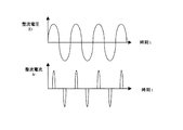
この回路に負荷を接続すると、図3に示すように、整流回路に印加する整流電圧(換言すると共振回路の出力電圧)Erは正弦波になるが、整流回路の電流Irは整流電圧の最大値近傍だけで急峻な電流が流れ、これは平滑コンデンサ10の容量が大きいほど顕著になる。
整流電流に含まれる周波数に着目すると、高周波電源の周波数と同じ基本波成分以外に、基本波の3倍、5倍、7倍といった奇数次高調波成分が多く含まれる。
一方、共振回路は、共振周波数よりも高い高次高調波に対してはインピーダンスが高くなり、高調波電流を阻止するように作用する。
When a load is connected to this circuit, as shown in FIG. 3, the rectified voltage (in other words, the output voltage of the resonant circuit) Er applied to the rectifier circuit becomes a sine wave, but the current Ir of the rectifier circuit is the maximum value of the rectified voltage. A steep current flows only in the vicinity, and this becomes more prominent as the capacity of the
Focusing on the frequency included in the rectified current, in addition to the fundamental wave component that is the same as the frequency of the high-frequency power supply, there are many odd-order harmonic components such as three times, five times, and seven times the fundamental wave.
On the other hand, the resonance circuit has a high impedance with respect to higher harmonics higher than the resonance frequency, and acts to block harmonic current.
そこで、整流回路と並列に高調波バイパスコンデンサ8を接続する。
高調波バイパスコンデンサ8では、受電コイル6の1次から2次への電力伝達の支配要因になる基本波成分は受電コイル6、共振回路を通り整流回路から負荷へ流れ、高調波成分は、高調波バイパスコンデンサ8を通り整流回路から負荷へ流れる経路を形成する。
高調波バイパスコンデンサ8の容量は、共振コンデンサの10〜20%程度の容量を選定する。これにより、平滑コンデンサの容量が大きい場合の受電効率を向上する。
Therefore, a
In the
As the capacity of the
高調波バイパスコンデンサ8は、直列共振回路に対しては共振周波数の変化の影響は軽微で、かつ、静電容量は固定のため容易に共振周波数の変化は補正が可能である。
高調波バイパスコンデンサ8は、高調波バイパスコンデンサがない場合には、整流回路から見た電源インピーダンスが鋭い共振特性により共振周波数近傍のみで低いインピーダンスを示すが、高調波バイパスコンデンサ8を付加することで、共振周波数よりも高い周波数に対しても整流回路から見た電源インピーダンスを下げるように作用し、高次高調波電流は高調波バイパスコンデンサ8から整流回路に流れる。
高次高調波電流を流れやすくすることで、高周波電源の出力である基本波電流も流れやすくなり、効率よく電力を2次側に伝達する。
The
When there is no harmonic bypass capacitor, the
By facilitating the flow of high-order harmonic current, the fundamental wave current that is the output of the high-frequency power source can also flow easily, and power is efficiently transmitted to the secondary side.
一方、大規模な非接触給電装置では複数の受電コイルを使用し、大きな電力を移動体で取り出す。この構成を図4に示す。
高周波電源に接続した給電線で、受電コイル11、12、13、14を励磁する。それぞれの受電コイルには、図2で説明した共振・整流回路15、16、17、18を接続し、整流回路の出力には電圧安定化回路19、20、21、22を接続する。
それぞれの電圧安定化回路の出力は、結合ダイオード23、24、25、26で結合する。
On the other hand, in a large-scale non-contact power feeding device, a plurality of power receiving coils are used, and a large amount of electric power is taken out by a moving body. This configuration is shown in FIG.
The power receiving
The outputs of the respective voltage stabilization circuits are coupled by
それぞれの受電コイルを含めた共振回路の出力電圧と出力電流の関係は、励磁電流が一定の条件でも、図5に示すように必ずしも全ての出力は一致しない。
すなわち、受電コイルのフェライトコアの透磁率、給電線と受電コイルの位置関係、温度、2次コイル巻線のインダクタンスの誤差、共振コンデンサの容量誤差などの複数の要因により違った値となる。
整流回路から見た電源のインピーダンスは、図5で示す電圧・電流の勾配の逆数になる。
As shown in FIG. 5, the relationship between the output voltage and the output current of the resonance circuit including each power receiving coil does not necessarily match all the outputs even when the excitation current is constant.
That is, the value varies depending on a plurality of factors such as the magnetic permeability of the ferrite core of the power receiving coil, the positional relationship between the power supply line and the power receiving coil, the temperature, the inductance error of the secondary coil winding, and the capacitance error of the resonance capacitor.
The impedance of the power supply viewed from the rectifier circuit is the reciprocal of the voltage / current gradient shown in FIG.
電圧安定化回路は、一般的なスイッチング電源と異なり、一定の出力電流以上では電圧が出力電流に比例して下がる垂下特性を持たせる。
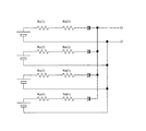
この電圧安定化回路は、等価的に図7に示すような回路となる。
各受電コイルの系統毎に、電源の内部抵抗Rc1、Rc2、Rc3、Rc4は異なった固有の値を持つ。電圧安定化回路は、負荷電流が少ない時は定電圧電源として作用するため出力インピーダンスRd1〜Rd4はゼロとなる。一定電流以上ではRd1〜Rd4は電流に比例して電圧が下がるため、一定の抵抗を持つ。
Unlike a general switching power supply, the voltage stabilization circuit has a drooping characteristic in which the voltage drops in proportion to the output current above a certain output current.
This voltage stabilization circuit is equivalent to a circuit as shown in FIG.
The internal resistances Rc1, Rc2, Rc3, and Rc4 of the power supply have different unique values for each power receiving coil system. Since the voltage stabilizing circuit acts as a constant voltage power source when the load current is small, the output impedances Rd1 to Rd4 are zero. Above a certain current, Rd1 to Rd4 have a certain resistance because the voltage drops in proportion to the current.
例えば、各受電コイルの系統で10kWの電力が供給できる給電装置で、かつ系統毎の内部抵抗RcがRc=1.5〜2.0Ω程度ある場合は、垂下特性として0.2〜0.5Ωを持たせる。
電源と負荷の間でこの2つが直列接続となり、電源インピーダンスのばらつきを小さくあるいは同一の値にすることができる。
For example, when the power supply device can supply 10 kW of power in each power receiving coil system and the internal resistance Rc for each system is about Rc = 1.5 to 2.0Ω, the drooping characteristic is 0.2 to 0.5Ω. To have.
These two are connected in series between the power source and the load, and variations in the power source impedance can be reduced or set to the same value.
給電容量の比較的小さい数kW程度のシステムでは、Rcの値が数Ωから10Ωと大きいため効果が少ないが、10kW以上のシステムでは、本実施例の構成により効率の良いかつ負荷のバランスの取れた給電装置となる。 In a system with a relatively small power supply capacity of about several kW, the Rc value is large, from several Ω to 10 Ω, so the effect is small. However, in a system of 10 kW or more, the configuration of this embodiment is efficient and the load can be balanced. Power supply device.
なお、本実施例では共振を直列共振で説明したが、並列共振の回路においては高調波バイパスコンデンサ8は無意味であるが、電圧安定化回路の垂下特性によりそれぞれの受電コイルの平準化は行える。
また、本実施例は4つの受電コイルの並列接続で説明したが、これに限定するものではなく、2つ以上の並列接続に適用できる。
In the present embodiment, the resonance is described as series resonance, but the
Moreover, although the present Example demonstrated by the parallel connection of four receiving coils, it is not limited to this, It can apply to two or more parallel connections.
以上、本発明の非接触給電装置について、その実施例に基づいて説明したが、本発明は上記実施例に記載した構成に限定されるものではなく、その趣旨を逸脱しない範囲において適宜その構成を変更することができる。 As mentioned above, although the non-contact electric power feeder of this invention was demonstrated based on the Example, this invention is not limited to the structure described in the said Example, The structure is suitably changed in the range which does not deviate from the meaning. Can be changed.
本発明の非接触給電装置は、複数の受電コイルから受電する電力を平準化することにより、一部の回路への負荷の集中を防止するという特性を有していることから、例えば、半導体工場等のクリーンルーム内で発塵を最小限に抑制するような搬送装置に好適に用いることができる。 The non-contact power feeding device of the present invention has a characteristic of preventing concentration of loads on some circuits by leveling power received from a plurality of power receiving coils. For example, it can be suitably used in a transport device that minimizes dust generation in a clean room.
1 フェライトコア
2 2次巻線
3 給電線
4 給電線支持材
5 高周波電源
6 受電コイル
7 共振コンデンサ
8 高調波バイパスコンデンサ
9 整流ダイオード
10 平滑コンデンサ
11〜14 受電コイル
15〜18 共振・整流回路
19〜22 電圧安定化回路
23〜26 結合ダイオード
DESCRIPTION OF
Claims (1)
Priority Applications (1)
| Application Number | Priority Date | Filing Date | Title |
|---|---|---|---|
| JP2007099586A JP4846646B2 (en) | 2007-04-05 | 2007-04-05 | Contactless power supply |
Applications Claiming Priority (1)
| Application Number | Priority Date | Filing Date | Title |
|---|---|---|---|
| JP2007099586A JP4846646B2 (en) | 2007-04-05 | 2007-04-05 | Contactless power supply |
Publications (2)
| Publication Number | Publication Date |
|---|---|
| JP2008259335A JP2008259335A (en) | 2008-10-23 |
| JP4846646B2 true JP4846646B2 (en) | 2011-12-28 |
Family
ID=39982356
Family Applications (1)
| Application Number | Title | Priority Date | Filing Date |
|---|---|---|---|
| JP2007099586A Expired - Fee Related JP4846646B2 (en) | 2007-04-05 | 2007-04-05 | Contactless power supply |
Country Status (1)
| Country | Link |
|---|---|
| JP (1) | JP4846646B2 (en) |
Cited By (1)
| Publication number | Priority date | Publication date | Assignee | Title |
|---|---|---|---|---|
| EP4148699A4 (en) * | 2020-05-07 | 2024-05-22 | Murata Machinery, Ltd. | Wireless sensor |
Families Citing this family (4)
| Publication number | Priority date | Publication date | Assignee | Title |
|---|---|---|---|---|
| JP6384780B2 (en) * | 2014-06-13 | 2018-09-05 | パナソニックIpマネジメント株式会社 | Contactless power supply system |
| JP5966038B1 (en) * | 2015-03-17 | 2016-08-10 | 株式会社ダイヘン | Contactless power supply system |
| WO2020142201A1 (en) | 2019-01-02 | 2020-07-09 | Ge Hybrid Technologies, Llc | Wireless power transmission using multiple transmitters and receivers |
| EP4059114B1 (en) * | 2019-11-12 | 2025-10-01 | GE Hybrid Technologies, LLC | Wireless power transfer with load sharing receivers |
Family Cites Families (5)
| Publication number | Priority date | Publication date | Assignee | Title |
|---|---|---|---|---|
| JPS61262821A (en) * | 1985-05-15 | 1986-11-20 | Origin Electric Co Ltd | System for controlling power source output |
| JP3522456B2 (en) * | 1996-07-29 | 2004-04-26 | 日立機電工業株式会社 | Non-contact power supply |
| JP3071697B2 (en) * | 1996-11-28 | 2000-07-31 | 甲府日本電気株式会社 | Output current correction method |
| JP3356135B2 (en) * | 1999-10-08 | 2002-12-09 | 三菱電機株式会社 | Mobile contactless power supply |
| JP2002354712A (en) * | 2001-05-22 | 2002-12-06 | Shinko Electric Co Ltd | Non-contact power supply |
-
2007
- 2007-04-05 JP JP2007099586A patent/JP4846646B2/en not_active Expired - Fee Related
Cited By (1)
| Publication number | Priority date | Publication date | Assignee | Title |
|---|---|---|---|---|
| EP4148699A4 (en) * | 2020-05-07 | 2024-05-22 | Murata Machinery, Ltd. | Wireless sensor |
Also Published As
| Publication number | Publication date |
|---|---|
| JP2008259335A (en) | 2008-10-23 |
Similar Documents
| Publication | Publication Date | Title |
|---|---|---|
| JP6371364B2 (en) | Non-contact power supply device | |
| CN101427454B (en) | Single phase power supply for inductively coupled power transfer systems | |
| CN103703663B (en) | A kind of device for reducing resonant-mode power supply | |
| CN103270562B (en) | The apparatus and method of the unidirectional magnetic flux in compensator transformer iron core | |
| CN103181050B (en) | Induced power transmits pick-up circuit | |
| JP4846646B2 (en) | Contactless power supply | |
| CN210074889U (en) | Wireless power transmission system with high anti-offset characteristic | |
| CN103733488A (en) | An inductively coupled power transfer receiver | |
| JP7087887B2 (en) | Switching power supply | |
| Tian et al. | Analysis of multi-coil omnidirectional energy harvester | |
| CN113162167B (en) | Wireless charging system with constant-current and constant-voltage automatic switching function | |
| CN109196767A (en) | power control circuit | |
| CN106208414B (en) | The inductive electric energy transmission system of more primary coils of the automatic resonance compensation of energy | |
| CN207124490U (en) | Power supply device and power transmission system | |
| CN104416266B (en) | Method for minimized harmonic load of welding power supply and welding power supply for executing method | |
| CN111245075A (en) | Wireless charging circuit and parameter selection method for realizing constant-power wireless charging | |
| RU2328051C2 (en) | Transformer | |
| CN101346870B (en) | A circuit that transmits amplified resonant power to a load | |
| CN109104883B (en) | Resonant power transmission | |
| JP2008289240A (en) | Active filter device and power conversion equipment | |
| CN108320892B (en) | A transformer and switching power supply | |
| WO2016208402A1 (en) | Power transmitting device, power receiving device, and power transmission system | |
| JP2020018060A (en) | Power receiving device and wireless power supply system | |
| CN102244469A (en) | Switching power supply capable of suppressing current harmonic waves | |
| Manjunatha et al. | Magnetic Coupling Resonant Wireless Power Transmission |
Legal Events
| Date | Code | Title | Description |
|---|---|---|---|
| A621 | Written request for application examination |
Free format text: JAPANESE INTERMEDIATE CODE: A621 Effective date: 20090730 |
|
| A977 | Report on retrieval |
Free format text: JAPANESE INTERMEDIATE CODE: A971007 Effective date: 20101126 |
|
| A131 | Notification of reasons for refusal |
Free format text: JAPANESE INTERMEDIATE CODE: A131 Effective date: 20110106 |
|
| TRDD | Decision of grant or rejection written | ||
| A01 | Written decision to grant a patent or to grant a registration (utility model) |
Free format text: JAPANESE INTERMEDIATE CODE: A01 Effective date: 20111005 |
|
| A01 | Written decision to grant a patent or to grant a registration (utility model) |
Free format text: JAPANESE INTERMEDIATE CODE: A01 |
|
| A61 | First payment of annual fees (during grant procedure) |
Free format text: JAPANESE INTERMEDIATE CODE: A61 Effective date: 20111012 |
|
| FPAY | Renewal fee payment (event date is renewal date of database) |
Free format text: PAYMENT UNTIL: 20141021 Year of fee payment: 3 |
|
| R150 | Certificate of patent or registration of utility model |
Free format text: JAPANESE INTERMEDIATE CODE: R150 |
|
| S111 | Request for change of ownership or part of ownership |
Free format text: JAPANESE INTERMEDIATE CODE: R313111 |
|
| R350 | Written notification of registration of transfer |
Free format text: JAPANESE INTERMEDIATE CODE: R350 |
|
| LAPS | Cancellation because of no payment of annual fees |