JP4843482B2 - Information processing apparatus and program - Google Patents
Information processing apparatus and program Download PDFInfo
- Publication number
- JP4843482B2 JP4843482B2 JP2006353033A JP2006353033A JP4843482B2 JP 4843482 B2 JP4843482 B2 JP 4843482B2 JP 2006353033 A JP2006353033 A JP 2006353033A JP 2006353033 A JP2006353033 A JP 2006353033A JP 4843482 B2 JP4843482 B2 JP 4843482B2
- Authority
- JP
- Japan
- Prior art keywords
- unit
- processing load
- input
- motion
- search
- Prior art date
- Legal status (The legal status is an assumption and is not a legal conclusion. Google has not performed a legal analysis and makes no representation as to the accuracy of the status listed.)
- Expired - Fee Related
Links
Images


Classifications
-
- H—ELECTRICITY
- H04—ELECTRIC COMMUNICATION TECHNIQUE
- H04N—PICTORIAL COMMUNICATION, e.g. TELEVISION
- H04N19/00—Methods or arrangements for coding, decoding, compressing or decompressing digital video signals
- H04N19/50—Methods or arrangements for coding, decoding, compressing or decompressing digital video signals using predictive coding
- H04N19/503—Methods or arrangements for coding, decoding, compressing or decompressing digital video signals using predictive coding involving temporal prediction
- H04N19/51—Motion estimation or motion compensation
- H04N19/57—Motion estimation characterised by a search window with variable size or shape
-
- H—ELECTRICITY
- H04—ELECTRIC COMMUNICATION TECHNIQUE
- H04N—PICTORIAL COMMUNICATION, e.g. TELEVISION
- H04N19/00—Methods or arrangements for coding, decoding, compressing or decompressing digital video signals
- H04N19/10—Methods or arrangements for coding, decoding, compressing or decompressing digital video signals using adaptive coding
- H04N19/134—Methods or arrangements for coding, decoding, compressing or decompressing digital video signals using adaptive coding characterised by the element, parameter or criterion affecting or controlling the adaptive coding
- H04N19/156—Availability of hardware or computational resources, e.g. encoding based on power-saving criteria
-
- H—ELECTRICITY
- H04—ELECTRIC COMMUNICATION TECHNIQUE
- H04N—PICTORIAL COMMUNICATION, e.g. TELEVISION
- H04N19/00—Methods or arrangements for coding, decoding, compressing or decompressing digital video signals
- H04N19/60—Methods or arrangements for coding, decoding, compressing or decompressing digital video signals using transform coding
- H04N19/61—Methods or arrangements for coding, decoding, compressing or decompressing digital video signals using transform coding in combination with predictive coding
Landscapes
- Engineering & Computer Science (AREA)
- Multimedia (AREA)
- Signal Processing (AREA)
- Computing Systems (AREA)
- Theoretical Computer Science (AREA)
- Compression Or Coding Systems Of Tv Signals (AREA)
Description
この発明は、例えばパーソナルコンピュータなどの情報処理装置に適用して好適な動画像の符号化技術に関する。 The present invention relates to a moving image encoding technique suitable for application to an information processing apparatus such as a personal computer.
近年、動画像をソフトウェアによって符号化するソフトウェアエンコーダを搭載するパーソナルコンピュータが普及し始めている。また、最近では、次世代の動画像圧縮符号化技術として、H.264/AVC(Advanced Video Coding)規格が注目されている。このH.264/AVC規格は、MPEG2やMPEG4のような従来の圧縮符号化技術よりも高能率の圧縮符号化技術である。このため、H.264/AVC規格に対応するエンコード処理においては、MPEG2やMPEG4のような従来の圧縮符号化技術よりも多くの処理量が必要とされる。このようなことから、これまでも、動画像のエンコード処理量を低減するための提案が種々なされている(例えば特許文献1等参照)。
H.264/AVC規格に対応するエンコード処理の中でも、動き検出処理は、複数参照フレームの選択が可能となったことで、最適な動きベクトルを検出するためのブロックマッチング回数が、従来の圧縮符号化技術よりも、フレーム数に比例して増大する。従って、(他のソフトウェアが並行して動作する可能性のある)パーソナルコンピュータ上で動作するソフトウェアエンコーダにおいては、例えばプロセッサの負荷などに応じて動き検出処理を適応的に省略する仕組みが強く望まれている。 H. Among the encoding processes corresponding to the H.264 / AVC standard, since the motion detection process can select a plurality of reference frames, the number of times of block matching for detecting an optimal motion vector can be reduced. Rather than in proportion to the number of frames. Therefore, in a software encoder that operates on a personal computer (where other software may operate in parallel), a mechanism that adaptively omits motion detection processing in accordance with, for example, the load on the processor is strongly desired. ing.
この発明は、このような事情を考慮してなされたものであり、動画像の符号化処理をスムーズに実行することを可能とした情報処理装置およびプログラムを提供することを目的とする。 The present invention has been made in view of such circumstances, and an object of the present invention is to provide an information processing apparatus and a program capable of smoothly executing a moving image encoding process.
実施形態によれば、動画像信号を符号化する情報処理装置は、処理負荷を検出する処理負荷検出部と、入力動画像信号が入力される入力部と、前記入力動画像信号をなす入力画像を分割したブロックに対して、一辺が前記ブロックの一辺と平行する矩形の領域と、対角線が前記ブロックの一辺と平行する正方形の領域との重複部分からなる探索範囲を設定し、矩形領域探索によってフレーム間での動き検出を行い、前記処理負荷検出部で検出した処理負荷が高くなるほど前記正方形の領域を小さくする動き検出部と、前記動き検出部の検出結果に基づき、予測信号を生成する動き補償予測部と、前記予測信号と前記入力画像信号との残差により得られる予測残差信号を直交変換して周波数成分へ変換する変換部と、前記変換部で変換された周波数成分を符号化し、符号化ストリームを出力する出力部とを備える。 According to the embodiment, an information processing apparatus for encoding a moving image signal, a processing load detector for detecting the processing load, and an input unit which input video signals are input, the input image constituting the said input video signal on the divided blocks, and set a rectangular area whose one side is parallel to one side of the block, the search range diagonal consisting overlap a region of the square parallel to one side of the block, by a rectangular area search There line motion detection between frames, based on the processing load and the motion detector detected processing load detecting unit is smaller the area of the square increases, the motion detector of the detection result, to generate a prediction signal a motion compensation prediction unit, a conversion unit converting the frequency components the orthogonal transform the prediction residual signal obtained by the residual between the prediction signal and the input image signal, the converted frequency by the converter unit The number component encoding, Ru and an output unit for outputting an encoded stream.
この発明によれば、動画像の符号化処理をスムーズに実行することを可能とする。 According to the present invention, it is possible to smoothly execute a moving image encoding process.
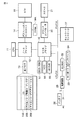
以下、図面を参照して、この発明の一実施形態を説明する。図1には、本実施形態に係る情報処理装置の構成例が示されている。この情報処理装置は、例えばバッテリ駆動可能なノートブック型パーソナルコンピュータ等として実現されている。 Hereinafter, an embodiment of the present invention will be described with reference to the drawings. FIG. 1 shows a configuration example of the information processing apparatus according to the present embodiment. This information processing apparatus is realized as, for example, a notebook personal computer that can be driven by a battery.
図1に示すように、このコンピュータは、CPU11、ノースブリッジ12、主メモリ13、グラフィックスコントローラ14、VRAM14A、LCD15、サウスブリッジ16、BIOS−ROM17、HDD18、HD DVD19、サウンドコントローラ20、スピーカ21、エンベデッドコントローラ/キーボードコントローラIC(EC/KBC)22、キーボード23、タッチパッド24、電源回路25,バッテリ26およびネットワークコントローラ27等を備えている。
As shown in FIG. 1, this computer includes a
CPU11は、本コンピュータ内の各部の動作を制御するプロセッサである。CPU11は、HDD18から主メモリ13にロードされるオペレーティングシステム(OS)100や、このOS100の制御下で動作する、ユーティリティを含む各種アプリケーションプログラムを実行する。この各種アプリケーションプログラムの中には、ビデオエンコーダ制御ユーティリティ200およびビデオエンコーダアプリケーション300が含まれている。
The
ビデオエンコーダアプリケーション300は、動画像を符号化するためのソフトウェアである。このビデオエンコーダアプリケーション300は、H.264/AVC規格に対応するソフトウェアエンコーダである。そして、ビデオエンコーダ制御ユーティリティ200は、ビデオエンコーダアプリケーション300によるビデオの処理負荷のほか、ビデオ以外のオーディオ、レンダリング等の処理負荷を考慮した、動画像の符号化に係る処理全体の負荷を検出し、この検出結果に基づき、ビデオエンコーダアプリケーション300によって実行されるエンコード処理の内容を制御する。より具体的には、動き検出処理を段階的に簡略化させる。
The
図2は、このビデオエンコーダ制御ユーティリティ200とビデオエンコーダアプリケーション300との関連を示す図である。
FIG. 2 is a diagram showing the relationship between the video
図2に示すように、ビデオエンコーダ制御ユーティリティ200は、ビデオエンコーダアプリケーション300からビデオエンコード処理負荷の情報を取得すると共に、このビデオエンコード処理負荷以外のオーティオ処理負荷およびレンダリング処理負荷等を収集して、動画像の符号化に係る処理全体の負荷を検出する。つまり、ビデオエンコーダ制御ユーティリティ200は、動画像の符号化に関わる処理負荷検出部として動作する。
As shown in FIG. 2, the video
ビデオエンコーダ制御ユーティリティ200は、検出した動画像の符号化に係る処理全体の負荷に応じた負荷情報を作成し、この負荷情報をビデオエンコーダアプリケーション300に供給する。そして、ビデオエンコーダアプリケーション300は、このビデオエンコーダ制御ユーティリティ200からの負荷情報に基づき、動き検出処理の段階的な簡略化を実施する。
The video
なお、CPU11は、BIOS−ROM17に格納されたBIOSも実行する。BIOSは、ハードウェア制御のためのプログラムである。
Note that the
ノースブリッジ12は、CPU11のローカルバスとサウスブリッジ16との間を接続するブリッジデバイスである。ノースブリッジ12は、バスを介してグラフィックスコントローラ14との通信を実行する機能を有しており、また、主メモリ13をアクセス制御するメモリコントローラも内蔵されている。グラフィックスコントローラ14は、本コンピュータのディスプレイモニタとして使用されるLCD15を制御する表示コントローラである。グラフィックスコントローラ14は、VRAM14Aに書き込まれた画像データからLCD15に送出すべき表示信号を生成する。
The
サウスブリッジ16は、PCIバスおよびLPCバス上の各種デバイスを制御するコントローラである。また、このサウスブリッジ16には、BIOS−ROM17、HDD18、HD DVD19およびサウンドコントローラ20が直接的に接続され、これらを制御する機能も有している。サウンドコントローラ20は、スピーカ21を制御する音源コントローラである。
The
EC/KBC22は、電力管理のためのエンベデッドコントローラと、キーボード23およびタッチパッド24を制御するためのキーボードコントローラとが集積された1チップマイクロコンピュータである。EC/KBC22は、電源回路25と協働して、バッテリ26または外部AC電源からの電力を各部に供給制御する。そして、ネットワークコントローラ27は、例えばインターネットなどの外部ネットワークとの通信を実行する通信装置である。
The EC / KBC 22 is a one-chip microcomputer in which an embedded controller for power management and a keyboard controller for controlling the
次に、図3を参照して、このようなハードウェア構成の本コンピュータ上で動作するビデオエンコーダアプリケーション300によって実現されるソフトウェアエンコーダの機能構成を説明する。図中、実線はデータの流れを、また、点線は制御信号の流れをそれぞれ示している。
Next, the functional configuration of the software encoder realized by the
ビデオエンコーダアプリケーション300によるエンコード処理は、H.264/AVC規格に対応しており、図示のように、ビデオエンコーダアプリケーション300は、符号化制御部301、変換・スケーリング部302、エントロピー符号化部303、スケーリング・逆変換部304、イントラ予測部305、デブロッキングフィルタ306、フレームバッファ307、動き検出部308、動き補償部309、可算器310,311、入力部312等を含んでなる。
The encoding process by the
ビデオエンコーダアプリケーション300は、符号化制御部301によって全体的な制御を司り、入力部312から入力される各画面(ピクチャ)の符号化を、たとえば16×16画素のマクロブロック単位で実行する。そして、マクロブロックごとに、フレーム内符号化モード(イントラ符号化モード)および動き補償フレーム間予測符号化モード(インター符号化モード)のいずれか一方を選択する。
The
イントラ符号化モードにおいては、イントラ予測部305が、符号化対象画面(ピクチャ)から予測信号s1を生成し、変換・スケーリング部302が、その予測信号を直交変換および量子化し、エントロピー符号化部303が、エントロピー符号化を行うことによって符号化する。
In the intra coding mode, the
一方、インター予測符号化モードにおいては、まず、動き検出部308が、フレームバッファ307に格納された既に符号化された画面(ピクチャ)からの動きを推定し、続いて、動き補償部309が、符号化対象画面に対応する動き補償フレーム間予測信号s2を定められた形状単位で生成する。そして、符号化対象画面(ピクチャ)から動き補償フレーム間予測信号s2を引いた予測誤差信号s3を、変換・スケーリング部302が、直交変換および量子化し、エントロピー符号化部303が、エントロピー符号化を行うことによって符号化する。
On the other hand, in the inter prediction encoding mode, first, the
また、スケーリング・逆変換部304は、直交変換および量子化された画像(ピクチャ)の量子化係数を逆量子化および逆直交変換するものであり、デブロッキングフィルタ306は、ブロックノイズを低減するためのデブロッキングフィルタ処理を行うものである。
The scaling /
このような機能構成を有するビデオエンコーダアプリケーション300に対してビデオエンコーダ制御ユーティリティ200から供給される負荷情報は、符号化制御部301によって受信される。H.264/AVC規格に対応するエンコード処理では、動き検出処理が、複数参照フレームの選択が可能となったことで、最適な動きベクトルを検出するためのブロックマッチング回数が、従来の圧縮符号化技術よりも、フレーム数に比例して増大する。そこで、このビデオエンコーダアプリケーション300では、ビデオエンコーダ制御ユーティリティ200で検出された負荷情報に応じて、符号化制御部301からの制御信号に基づき、動き検出処理を段階的に簡略化する仕組みを動き検出部308に設ける。以下、この仕組みについて詳述する。
Load information supplied from the video
ここでは、H.264/AVC規格の符号化モード選択方法として、符号化歪と符号量とが最適な組み合わせを選択するRate-Distortion最適法(以下、RDOとも称する)を用い、また、動き検出のアルゴリズムとして、フルペルサーチや階層サーチなどの矩形領域探索を用いることを想定する。 Here, H. As a coding mode selection method of the H.264 / AVC standard, a rate-distortion optimal method (hereinafter also referred to as RDO) that selects an optimal combination of coding distortion and code amount is used. Assume that a rectangular area search such as a pel search or a hierarchical search is used.
動き検出処理(以下、MEとも称する)におけるRDOでは、(3)式に示すコスト関数を用いて、出力のコストJが最小となる動きベクトルmを最適なものとして選択する。 In the RDO in the motion detection process (hereinafter also referred to as ME), the motion vector m that minimizes the output cost J is selected as the optimum using the cost function shown in the equation (3).
J=SAD(m)+λM×R(m)…(3)式
SAD(m):予測誤差信号の絶対値和
λM:ラグランジュ乗数
R(m):差分ベクトルの符号量と参照インデックスの符号量の和
あるパーティションに対して、ME処理済みの参照フレームに対する結果で得られた動きベクトルにおけるSAD,符号量,コストをもとに、それ以外の参照フレームに対するMEの実行およびパラメータ(探索中心および探索範囲など)を決定する。図4は、本ビデオエンコーダアプリケーション300の動き検出部308が実行する動き検出処理の動作手順を示すフローチャートである。
J = SAD (m) + λ M × R (m) (3)
SAD (m): sum of absolute values of prediction error signal
λ M : Lagrange multiplier
R (m): Sum of code amount of difference vector and code amount of reference index For a certain partition, based on SAD, code amount, and cost in the motion vector obtained as a result of the reference frame after ME processing, The ME execution and parameters (search center, search range, etc.) for other reference frames are determined. FIG. 4 is a flowchart showing an operation procedure of motion detection processing executed by the
まず、動き検出部308は、フレームバッファ307に格納された符号化済みのフレームの中から、最初にMEを実行する参照フレームを選択する(ステップA1)。時間的に近い参照フレームから選択しても良いし、近傍ブロックで参照されたフレームの状況から選択しても良い。
First, the
次に、探索中心を選択する(ステップA2)。ゼロ点ベクトル、予測ベクトル、MV0を時間軸に対して比例配分した、いわゆるテレスコピックサーチで用いるベクトル(ただし、SAD0が大きすぎない場合)の各位置でSADを算出し、これらの内で最小SADのものを探索中心とする。 Next, the search center is selected (step A2). The SAD is calculated at each position of a vector used in so-called telescopic search (provided that SAD0 is not too large) in which the zero point vector, the prediction vector, and MV0 are proportionally distributed with respect to the time axis, and the minimum SAD of these is calculated. Focus on things.
この探索中心でのSAD,符号量,コストをそれぞれSAD0,R0,J0とした際、SAD0が十分に小さい場合は(ステップA3のYES)、現パーティションに対するMEをその時点で終了する(ステップA4,A7のYES)。一方、そうでなければ(ステップA3のNo)、前記(3)式で得られるコストを考慮した探索範囲を設定する(ステップA5)。そして、この探索範囲の設定機構が、動き検出処理を段階的に簡略化するために設けられた仕組みである。 When SAD, code amount, and cost at the search center are SAD0, R0, and J0, respectively, if SAD0 is sufficiently small (YES in step A3), the ME for the current partition is terminated at that time (step A4, step A4). A7 YES). On the other hand, if not (No in step A3), a search range is set in consideration of the cost obtained by the equation (3) (step A5). The search range setting mechanism is a mechanism provided to simplify the motion detection process step by step.
より具体的に説明すると、探索範囲探索中心位置におけるSAD,差分ベクトルおよび参照インデックスの符号量をそれぞれSAD1,R1とし、これから実行するMEにより求められるベクトルにおけるSAD,差分ベクトルおよび参照インデックスの符号量,コストをそれぞれSAD2,R2,J2とすると、このコストJ2がJ0より小さくなるベクトルを探索すれば十分である。ここで、
SAD2=SAD1−ΔESAD…(4)式
ΔESAD:探索で減少するSADの期待値
とする。
More specifically, the code amounts of the SAD, the difference vector, and the reference index at the search range search center position are respectively SAD1, R1, and the code amount of the SAD, the difference vector, and the reference index in the vector obtained from the ME to be executed from now on, If the costs are SAD2, R2, and J2, respectively, it is sufficient to search for a vector in which the cost J2 is smaller than J0. here,
SAD2 = SAD1-ΔE SAD (4)
ΔE SAD : The expected value of SAD that decreases in the search.
探索で減少するSADの期待値(ΔESAD)は、経験的な値でも良いし、過去にMEを行ったときに得られた結果から決めても良い。例えば、図4に示す、符号化対象マクロブロックに隣接するマクロブロックの動き検出における探索中心のSADと最終SADとの差ΔSADの平均値などとしても良い。 The expected value (ΔE SAD ) of SAD that decreases by the search may be an empirical value or may be determined from the results obtained when performing ME in the past. For example, the average value of the difference ΔSAD between the search center SAD and the final SAD in the motion detection of the macroblock adjacent to the encoding target macroblock shown in FIG. 4 may be used.
ここで、探索範囲の条件であるJ2<J0と、前記(3)式および前記(4)式を用いると、
まず、前記(3)式、
J0(過去のME結果のコスト)=SAD0+λM×R0
J1(探索中心のコスト) =SAD1+λM×R1
J2 =SAD2+λM×R2
からJ2<J0を満たすのは、
SAD2+λM×R2<SAD0+λM×R0
=R2<R0−(SAD2−SAD0)/λM
となる。
Here, using J2 <J0 as the search range condition, and the above equations (3) and (4),
First, the equation (3),
J0 (cost of past ME result) = SAD0 + λ M × R0
J1 (cost of search center) = SAD1 + λ M × R1
J2 = SAD2 + λ M × R2
Satisfying J2 <J0 from
SAD2 + λ M × R2 <SAD0 + λ M × R0
= R2 <R0- (SAD2-SAD0) / λ M
It becomes.
このSAD2に前記(4)式の右辺をおくと、
R2<R0−(SAD1−ΔESAD−SAD0)/λM
が導き出せる。
When the right side of the equation (4) is placed in this SAD2,
R2 <R0− (SAD1−ΔE SAD −SAD0) / λ M
Can be derived.
そこで、本ビデオエンコーダアプリケーション300の動き検出部308は、
R2(m)<R0−(SAD1−α×ΔESAD−SAD0)/λM…(5)式
を満たすベクトルmすべてを探索を行う領域(正方形の領域)とする。前記(5)式に示すように、ΔESADの部分にαを設けることにより、負荷レベルに応じて、探索範囲を可変とすることを実現している。αは、0以上1以下の範囲内に含まれるいずれかの定数であり、図6に示すように、負荷レベルが高いほど小さい値となる。
Therefore, the
R2 and (m) <R0- (SAD1- α × ΔE SAD -SAD0) / λ M ... (5) region for searching all vectors m satisfying Equation (square region). As shown in the equation (5), by providing α in the ΔESAD portion, the search range can be made variable according to the load level. α is any constant included in the range of 0 or more and 1 or less, and becomes smaller as the load level is higher as shown in FIG.
即ち、まず、ビデオエンコーダ制御ユーティリティ200が、動画像の符号化に係る処理全体の負荷を検出し(ステップB1)、ビデオエンコーダアプリケーション300の符号化制御部301が、このビデオエンコーダ制御ユーティリティ200からの負荷情報から負荷レベルを判定する(ステップB2)。そして、この判定結果を制御信号として受けたビデオエンコーダアプリケーション300の動き検出部308は、当該負荷レベルに応じた値をαとして設定する(ステップB3〜B6)。図7乃至図11に、本ビデオエンコーダアプリケーション300の動き検出部308によって設定される探索範囲の概念図を示す。
That is, first, the video
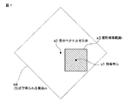
図7および図8には、矩形探索範囲の中心(x1)と差分ベクトルがゼロとなる点(x2)(前記(5)式で得られる集合の中心)とがずれている場合の探索範囲の例が示されている。矩形探索範囲r(x3)(矩形の領域)は、エンコーダパラメータ等で設定される値であり、本ビデオエンコーダアプリケーション300の操作者によって予め与えられる。矩形探索範囲r(x3)は、対象ブロックの辺と平行する辺を有する矩形として設定される。図7は、矩形探索範囲r(x3)すべてが前記(5)式で得られる集合m(x4)(正方形の領域)に含まれる場合、図8は、矩形探索範囲rの一部が前記(5)式で得られる集合m(x4)に含まれる場合、をそれぞれ示している。図示のように、対象ブロックの辺と平行する辺を有する矩形の矩形探索範囲r(x3)と、対象ブロックの一辺と対角線が平行する正方形の前記(5)式で得られる集合m(x4)との重複部分(斜線部分)が、探索範囲として設定される。
7 and 8, the search range when the center (x1) of the rectangular search range and the point (x2) where the difference vector becomes zero (the center of the set obtained by the above equation (5)) is shifted. An example is shown. The rectangular search range r (x3) (rectangular region) is a value set by an encoder parameter or the like, and is given in advance by the operator of the
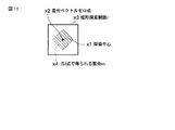
また、図9乃至図11には、矩形探索範囲の中心(x1)と差分ベクトルがゼロとなる点(x2)(前記(5)式で得られる集合の中心)とが一致する場合の探索範囲の例が示されている。図9は、矩形探索範囲r(x3)すべてが前記(5)式で得られる集合m(x4)に含まれる場合、図10および図11は、矩形探索範囲rの一部が前記(5)式で得られる集合m(x4)に含まれる場合、をそれぞれ示している。図示のように、前述と同様、対象ブロックの辺と平行する辺を有する矩形の矩形探索範囲r(x3)と、同ブロックの一辺と対角線が平行する正方形の前記(5)式で得られる集合m(x4)との重複部分(斜線部分)が探索範囲として設定される。 9 to 11 show the search range when the center (x1) of the rectangular search range coincides with the point (x2) where the difference vector becomes zero (the center of the set obtained by the equation (5)). An example of is shown. FIG. 9 shows a case where all of the rectangular search range r (x3) is included in the set m (x4) obtained by the equation (5), and FIGS. 10 and 11 show that a part of the rectangular search range r is the above (5). In the case of being included in the set m (x4) obtained by the equation, each is shown. As shown in the figure, as described above, a rectangular search range r (x3) having a side parallel to the side of the target block, and a set obtained by the above formula (5) having a square parallel to one side of the block. An overlapping portion (shaded portion) with m (x4) is set as a search range.
この探索範囲を設定すると、選択された参照フレームに対するMEを実行する(ステップA6)。そして、この時に得られたベクトルに対するSAD,符号量,コストをそれぞれSAD0,R0,J0とした際、SAD0が十分に小さい場合は(ステップA7のYes)、現パーティションに対するMEをその時点で終了する。 When this search range is set, ME for the selected reference frame is executed (step A6). When SAD, code amount, and cost for the vector obtained at this time are SAD0, R0, and J0, respectively, if SAD0 is sufficiently small (Yes in step A7), the ME for the current partition is terminated at that time. .
もし、そうでなければ(ステップA7のNo)、次にMEを実行する参照フレームを選択し(ステッップA8)、前述のステップA2〜A6に対応するステップA10〜A15の処理を、そのSAD,符号量,コストをそれぞれSAD0,R0,J0とした際、SAD0が十分に小さいベクトルが選択されるまで繰り返す。なお、次にMEを実行する参照フレームが無くなった場合は(ステップA9のNo)、現パーティションに対するMEをその時点で終了し、また、ステップA10での探索中心の選択は、さらに、それまで最適とされるベクトルに対するSAD0より値が小さいものを対象とする。 If not (No in Step A7), a reference frame for executing the next ME is selected (Step A8), and the processing in Steps A10 to A15 corresponding to the above Steps A2 to A6 is performed using the SAD, code When the quantity and cost are SAD0, R0, and J0, respectively, the process is repeated until a vector having a sufficiently small SAD0 is selected. If there is no reference frame for executing the next ME (No in step A9), the ME for the current partition is terminated at that time, and the selection of the search center in step A10 is further optimal until then. A vector whose value is smaller than SAD0 for a vector to be taken as a target is considered.
このように、本コンピュータによれば、動画像の符号化時における動き検出処理を段階的に簡略化させることが可能となる。 As described above, according to the present computer, it is possible to simplify the motion detection process at the time of encoding a moving image step by step.
ところで、以上では、動き検出のアルゴリズムとして、フルペルサーチや階層サーチなどの矩形領域探索を用いることを想定した。もし、動き検出のアルゴリズムとして、ダイヤモンドサーチやヘキサゴンサーチなどの簡略化探索を用いる場合には、探索範囲ではなく探索移動距離の上限を設定することで同様の制御か可能である。つまり、前記(3)式で得られるコストを考慮した探索移動距離を設定する。 In the above, it is assumed that a rectangular area search such as a full-pel search or a hierarchical search is used as a motion detection algorithm. If a simplified search such as diamond search or hexagon search is used as the motion detection algorithm, the same control can be performed by setting the upper limit of the search movement distance instead of the search range. That is, the search movement distance is set in consideration of the cost obtained by the equation (3).
この場合、前記(5)式を満たすベクトルmで探索中心からの距離が最大となるものを探索移動距離とする。前述と同様、負荷レベルに応じて、αの値を設定することで、探索移動距離を可変とすることを実現する。 In this case, the vector m satisfying the above equation (5) having the maximum distance from the search center is set as the search movement distance. As described above, the search movement distance can be made variable by setting the value of α according to the load level.
また、ビデオエンコーダ制御ユーティリティ200は、動画像の符号化に関わる処理負荷検出部として動作するものとして説明したが、例えばCPU11の負荷や、バッテリ26の残量などを検出するものとして変更することは容易である。即ち、動画像の符号化時における動き検出処理を段階的に簡略化させる基準を、CPU11の負荷やバッテリ26の残量に変更することは本手法の範疇である。
Further, the video
つまり、本発明は上記実施形態そのままに限定されるものではなく、実施段階ではその要旨を逸脱しない範囲で構成要素を変形して具体化できる。また、上記実施形態に開示されている複数の構成要素の適宜な組み合わせにより、種々の発明を形成できる。例えば、実施形態に示される全構成要素から幾つかの構成要素を削除してもよい。さらに、異なる実施形態にわたる構成要素を適宜組み合わせてもよい。 That is, the present invention is not limited to the above-described embodiment as it is, and can be embodied by modifying the constituent elements without departing from the scope of the invention in the implementation stage. In addition, various inventions can be formed by appropriately combining a plurality of components disclosed in the embodiment. For example, some components may be deleted from all the components shown in the embodiment. Furthermore, constituent elements over different embodiments may be appropriately combined.
11…CPU、12…ノースブリッジ、13…主メモリ、14…グラフィックスコントローラ、14A…VRAM、15…LCD、16…サウスブリッジ、17…BIOS−ROM、18…HDD、19…HD DVD、20…サウンドコントローラ、21…スピーカ、22…エンベデッドコントローラ/キーボードコントローラIC(EC/KBC)、23…キーボード、24…タッチパッド、25…電源回路、26…バッテリ、27…ネットワークコントローラ、100…オペレーティングシステム(OS)、200…ビデオエンコーダ制御ユーティリティ、300…ビデオエンコーダアプリケーション、301…符号化制御部、302…変換・スケーリング部、303…エントロピー符号化部、304…スケーリング・逆変換部、305…イントラ予測部、306…デブロッキングフィルタ、307…フレームバッファ、308…動き検出部、309…動き補償部、310,311…可算器、312…入力部。 11 ... CPU, 12 ... North Bridge, 13 ... Main Memory, 14 ... Graphics Controller, 14A ... VRAM, 15 ... LCD, 16 ... South Bridge, 17 ... BIOS-ROM, 18 ... HDD, 19 ... HD DVD, 20 ... Sound controller, 21 ... Speaker, 22 ... Embedded controller / keyboard controller IC (EC / KBC), 23 ... Keyboard, 24 ... Touchpad, 25 ... Power supply circuit, 26 ... Battery, 27 ... Network controller, 100 ... Operating system (OS) , 200 ... Video encoder control utility, 300 ... Video encoder application, 301 ... Coding control unit, 302 ... Transform / scaling unit, 303 ... Entropy coding unit, 304 ... Scaling / inverse transform unit, 30 ... intra prediction unit, 306 ... deblocking filter, 307 ... frame buffer, 308 ... motion detection portion, 309 ... motion compensation unit, 310, 311 ... countable unit, 312 ... input section.
Claims (8)
処理負荷を検出する処理負荷検出部と、
入力動画像信号が入力される入力部と、
前記入力動画像信号をなす入力画像を分割したブロックに対して、一辺が前記ブロックの一辺と平行する矩形の領域と、対角線が前記ブロックの一辺と平行する正方形の領域との重複部分からなる探索範囲を設定し、矩形領域探索によってフレーム間での動き検出を行い、前記処理負荷検出部で検出した処理負荷が高くなるほど前記正方形の領域を小さくする動き検出部と、
前記動き検出部の検出結果に基づき、予測信号を生成する動き補償予測部と、
前記予測信号と前記入力画像信号との残差により得られる予測残差信号を直交変換して周波数成分へ変換する変換部と、
前記変換部で変換された周波数成分を符号化し、符号化ストリームを出力する出力部と
を備える情報処理装置。 An information processing apparatus for encoding a moving image signal,
A processing load detector for detecting the processing load;
An input unit to which an input moving image signal is input;
For a block obtained by dividing the input image forming the input moving image signal, a search including an overlapping portion of a rectangular area whose one side is parallel to one side of the block and a square area whose diagonal line is parallel to one side of the block set the range, and a motion detector which have line motion detection between frames, to reduce the area of the square as detected processing load is higher in the processing load detecting unit by a rectangular area search,
A motion compensated prediction unit that generates a prediction signal based on the detection result of the motion detection unit;
A transform unit that orthogonally transforms a prediction residual signal obtained by a residual between the prediction signal and the input image signal to convert it into a frequency component ;
The encoding the converted frequency component by the conversion unit, information Ru and an output unit for outputting an encoded stream paper processing apparatus.
R2(m)<R0−(SAD1−α×ΔESAD−SAD0)/λM…(1)式
を満たす動きベクトルmすべてを前記正方形の領域とするものであって、前記処理負荷検出部で検出した処理負荷に応じて前記(1)式中の定数であるαを0以上1以下の範囲内に含まれるいずれかの値とすることにより、動き検出を行う領域を設定する請求項1記載の情報処理装置。 The movement detection section decreases the absolute value sum of the differences image image of the reference image and the original image SAD, the Lagrangian multiplier of lambda M, the sum of the code amount and the code amount of the reference index of the difference vector R, the search When the expected value of SAD is ΔE SAD , SAD and R in the motion vector that is optimal at that time are SAD0 and R0, SAD at the search center position is SAD1, and R in the motion vector to be detected is R2 ,
R2 (m) <R0− (SAD1−α × ΔE SAD −SAD0) / λ M (1) All motion vectors m satisfying the equation (1) are set as the square area, and detected by the processing load detection unit. with one of the values included in response to said the processing load of the α is a constant (1) where in the range of 0 to 1 inclusive, 請 Motomeko 1 to set the area for motion detection The information processing apparatus described.
前記動き検出部は、前記処理負荷検出部が検出したプロセッサの処理負荷に基づき、探索範囲を設定する請求項1記載の情報処理装置。 The processing load detection unit has means for detecting a load on the processor,
The movement detection unit, the processing load detecting unit based on the processing load of the processor has detected that the information processing apparatus 請 Motomeko 1, wherein to set the search range.
前記動き検出部は、前記処理負荷検出部が検出したバッテリの残量に基づき、動き検出を行う領域を設定する請求項1記載の情報処理装置。 The processing load detection unit detects a remaining battery level,
The movement detection unit, the processing load detecting unit based on the remaining capacity of the battery detected is, the information processing apparatus 請 Motomeko 1, wherein to set the area for motion detection.
処理負荷を検出する処理負荷検出部と、
入力動画像信号が入力される入力部と、
前記入力動画像信号をなす入力画像を分割したブロックに対して、前記処理負荷検出部で検出した処理負荷が高くなるほど小さく探索移動距離の上限を設定し、簡略化探索によってフレーム間での動き検出を行う動き検出部と、
前記動き検出部の検出結果に基づき、予測信号を生成する動き補償予測部と、
前記予測信号と前記入力画像信号との残差により得られる予測残差信号を直交変換して周波数成分へ変換する変換部と、
前記変換部で変換された周波数成分を符号化し、符号化ストリームを出力する出力部と
を備える情報処理装置。 An information processing apparatus for encoding a moving image signal,
A processing load detector for detecting the processing load;
An input unit to which an input moving image signal is input;
For the block obtained by dividing the input image forming the input moving image signal, the upper limit of the search movement distance is set as the processing load detected by the processing load detection unit increases , and motion detection between frames is performed by simplified search. A motion detector for performing
A motion compensated prediction unit that generates a prediction signal based on the detection result of the motion detection unit;
A transform unit that orthogonally transforms a prediction residual signal obtained by a residual between the prediction signal and the input image signal to convert it into a frequency component;
An output unit that encodes the frequency component converted by the conversion unit and outputs an encoded stream;
An information processing apparatus comprising:
R2(m)<R0−(SAD1−α×ΔESAD−SAD0)/λM…(2)式
を満たす動きベクトルmで探索中心からの距離が最大となるものを探索移動距離とするものであって、前記処理負荷検出部で検出した処理負荷に応じて前記(2)式中の定数であるαを0以上1以下の範囲内に含まれるいずれかの値とすることにより、探索移動距離の上限を設定する請求項5記載の情報処理装置。 The movement detection section decreases the absolute value sum of the differences image image of the reference image and the original image SAD, the Lagrangian multiplier of lambda M, the sum of the code amount and the code amount of the reference index of the difference vector R, the search When the expected value of SAD is ΔE SAD , SAD and R in the motion vector that is optimal at that time are SAD0 and R0, SAD at the search center position is SAD1, and R in the motion vector to be detected is R2 ,
R2 (m) <R0- be those distance from the search center motion vector m that satisfies (SAD1-α × ΔE SAD -SAD0 ) / λ M ... (2) formula is searched travel what the maximum Then, according to the processing load detected by the processing load detecting unit, α, which is a constant in the formula (2), is set to any value within the range of 0 or more and 1 or less. the information processing apparatus 請 Motomeko 5, wherein to set the upper limit.
処理負荷を検出する処理負荷検出部、
入力動画像信号が入力される入力部、
前記入力動画像信号をなす入力画像を分割したブロックに対して、一辺が前記ブロックの一辺と平行する矩形の領域と、対角線が前記ブロックの一辺と平行する正方形の領域との重複部分からなる探索範囲を設定し、矩形領域探索によってフレーム間での動き検出を行い、前記処理負荷検出部で検出した処理負荷が高くなるほど前記正方形の領域を小さくする動き検出部、
前記動き検出部の検出結果に基づき、予測信号を生成する動き補償予測部、
前記予測信号と前記入力画像信号との残差により得られる予測残差信号を直交変換して周波数成分へ変換する変換部、
前記変換部で変換された周波数成分を符号化し、符号化ストリームを出力する出力部
として機能させるためのプログラム。 A computer that encodes a video signal;
A processing load detector for detecting the processing load,
An input unit to which an input moving image signal is input;
For a block obtained by dividing the input image forming the input moving image signal, a search including an overlapping portion of a rectangular area whose one side is parallel to one side of the block and a square area whose diagonal line is parallel to one side of the block set the range, have rows motion detection between frames by a rectangular area search, the processing motion detection unit load detection detected processing load unit becomes smaller the area of the square higher,
A motion compensation prediction unit that generates a prediction signal based on a detection result of the motion detection unit;
A transform unit that orthogonally transforms a prediction residual signal obtained by a residual between the prediction signal and the input image signal into a frequency component ;
A program for encoding a frequency component converted by the conversion unit and causing it to function as an output unit that outputs an encoded stream.
処理負荷を検出する処理負荷検出部、
入力動画像信号が入力される入力部、
前記入力動画像信号をなす入力画像を分割したブロックに対して、前記処理負荷検出部で検出した処理負荷が高くなるほど小さく探索移動距離の上限を設定し、簡略化探索によってフレーム間での動き検出を行う動き検出部、
前記動き検出部の検出結果に基づき、予測信号を生成する動き補償予測部、
前記予測信号と前記入力画像信号との残差により得られる予測残差信号を直交変換して周波数成分へ変換する変換部、
前記変換部で変換された周波数成分を符号化し、符号化ストリームを出力する出力部
として機能させるためのプログラム。 A computer that encodes a video signal;
A processing load detector for detecting the processing load,
An input unit to which an input moving image signal is input;
For the block obtained by dividing the input image forming the input moving image signal, the upper limit of the search movement distance is set as the processing load detected by the processing load detection unit increases , and motion detection between frames is performed by simplified search. A motion detector,
A motion compensation prediction unit that generates a prediction signal based on a detection result of the motion detection unit;
A transform unit that orthogonally transforms a prediction residual signal obtained by a residual between the prediction signal and the input image signal into a frequency component;
An output unit that encodes the frequency component converted by the conversion unit and outputs an encoded stream
Program to function as .
Priority Applications (2)
| Application Number | Priority Date | Filing Date | Title |
|---|---|---|---|
| JP2006353033A JP4843482B2 (en) | 2006-12-27 | 2006-12-27 | Information processing apparatus and program |
| US11/940,767 US8130839B2 (en) | 2006-12-27 | 2007-11-15 | Information processing apparatus with video encoding process control based on detected load |
Applications Claiming Priority (1)
| Application Number | Priority Date | Filing Date | Title |
|---|---|---|---|
| JP2006353033A JP4843482B2 (en) | 2006-12-27 | 2006-12-27 | Information processing apparatus and program |
Publications (2)
| Publication Number | Publication Date |
|---|---|
| JP2008167048A JP2008167048A (en) | 2008-07-17 |
| JP4843482B2 true JP4843482B2 (en) | 2011-12-21 |
Family
ID=39583956
Family Applications (1)
| Application Number | Title | Priority Date | Filing Date |
|---|---|---|---|
| JP2006353033A Expired - Fee Related JP4843482B2 (en) | 2006-12-27 | 2006-12-27 | Information processing apparatus and program |
Country Status (2)
| Country | Link |
|---|---|
| US (1) | US8130839B2 (en) |
| JP (1) | JP4843482B2 (en) |
Families Citing this family (26)
| Publication number | Priority date | Publication date | Assignee | Title |
|---|---|---|---|---|
| US20100074336A1 (en) * | 2008-09-25 | 2010-03-25 | Mina Goor | Fractional motion estimation engine |
| JP5686499B2 (en) * | 2009-01-22 | 2015-03-18 | 株式会社Nttドコモ | Image predictive encoding apparatus, method and program, image predictive decoding apparatus, method and program, and encoding / decoding system and method |
| US8379728B2 (en) * | 2009-04-17 | 2013-02-19 | Texas Instruments Incorporated | Adaptive real-time video prediction mode method and computer-readable medium and processor for storage and execution thereof |
| US8705623B2 (en) * | 2009-10-02 | 2014-04-22 | Texas Instruments Incorporated | Line-based compression for digital image data |
| US9538128B2 (en) * | 2011-02-28 | 2017-01-03 | Cisco Technology, Inc. | System and method for managing video processing in a network environment |
| US9501915B1 (en) | 2014-07-07 | 2016-11-22 | Google Inc. | Systems and methods for analyzing a video stream |
| US9213903B1 (en) | 2014-07-07 | 2015-12-15 | Google Inc. | Method and system for cluster-based video monitoring and event categorization |
| US10140827B2 (en) | 2014-07-07 | 2018-11-27 | Google Llc | Method and system for processing motion event notifications |
| US9082018B1 (en) | 2014-09-30 | 2015-07-14 | Google Inc. | Method and system for retroactively changing a display characteristic of event indicators on an event timeline |
| USD782495S1 (en) | 2014-10-07 | 2017-03-28 | Google Inc. | Display screen or portion thereof with graphical user interface |
| US9361011B1 (en) | 2015-06-14 | 2016-06-07 | Google Inc. | Methods and systems for presenting multiple live video feeds in a user interface |
| WO2017120551A1 (en) * | 2016-01-08 | 2017-07-13 | Rehabilitation Institute Of Chicago | Convex relaxion regression systems and related methods |
| US10506237B1 (en) | 2016-05-27 | 2019-12-10 | Google Llc | Methods and devices for dynamic adaptation of encoding bitrate for video streaming |
| US10957171B2 (en) | 2016-07-11 | 2021-03-23 | Google Llc | Methods and systems for providing event alerts |
| US10192415B2 (en) | 2016-07-11 | 2019-01-29 | Google Llc | Methods and systems for providing intelligent alerts for events |
| US10380429B2 (en) | 2016-07-11 | 2019-08-13 | Google Llc | Methods and systems for person detection in a video feed |
| CN106851298B (en) * | 2017-03-22 | 2020-04-03 | 腾讯科技(深圳)有限公司 | High-efficiency video coding method and device |
| WO2018195440A1 (en) * | 2017-04-21 | 2018-10-25 | Zenimax Media Inc. | Systems and methods for rendering & pre-encoded load estimation based encoder hinting |
| US10313679B2 (en) | 2017-04-21 | 2019-06-04 | ZeniMaz Media Inc. | Systems and methods for encoder-guided adaptive-quality rendering |
| CN108810531B (en) * | 2017-05-03 | 2019-11-19 | 腾讯科技(深圳)有限公司 | Video coding processing method, device and electronic equipment |
| US11783010B2 (en) | 2017-05-30 | 2023-10-10 | Google Llc | Systems and methods of person recognition in video streams |
| US10410086B2 (en) | 2017-05-30 | 2019-09-10 | Google Llc | Systems and methods of person recognition in video streams |
| US10664688B2 (en) | 2017-09-20 | 2020-05-26 | Google Llc | Systems and methods of detecting and responding to a visitor to a smart home environment |
| US11134227B2 (en) | 2017-09-20 | 2021-09-28 | Google Llc | Systems and methods of presenting appropriate actions for responding to a visitor to a smart home environment |
| CN117640961A (en) * | 2018-03-19 | 2024-03-01 | 英迪股份有限公司 | Image decoding method, image encoding method and recording medium for storing bit stream |
| US11893795B2 (en) | 2019-12-09 | 2024-02-06 | Google Llc | Interacting with visitors of a connected home environment |
Family Cites Families (10)
| Publication number | Priority date | Publication date | Assignee | Title |
|---|---|---|---|---|
| JP3283159B2 (en) * | 1995-07-07 | 2002-05-20 | 日本電信電話株式会社 | Image coding method by software |
| JP3968161B2 (en) * | 1996-12-26 | 2007-08-29 | ユナイテッド・モジュール・コーポレーション | Motion vector detection device and recording medium |
| JP2001346216A (en) | 2000-06-06 | 2001-12-14 | Toshiba Corp | Moving image compression method and information processing apparatus |
| JP2002010261A (en) | 2000-06-16 | 2002-01-11 | Nec Corp | Image coding transform apparatus |
| JP4151374B2 (en) | 2002-03-29 | 2008-09-17 | セイコーエプソン株式会社 | Moving picture coding apparatus and moving picture coding method |
| US7400680B2 (en) * | 2003-09-30 | 2008-07-15 | Intel Corporation | Rectangular-shape motion search |
| US7362809B2 (en) * | 2003-12-10 | 2008-04-22 | Lsi Logic Corporation | Computational reduction in motion estimation based on lower bound of cost function |
| JP2005223631A (en) * | 2004-02-05 | 2005-08-18 | Sony Corp | Data processing apparatus and method, encoding apparatus, and decoding apparatus |
| TWI256259B (en) * | 2005-03-21 | 2006-06-01 | Pixart Imaging Inc | Improved diamond search and dynamic estimation method |
| JP4446288B2 (en) * | 2005-03-25 | 2010-04-07 | カシオ計算機株式会社 | Movie recording apparatus and movie recording processing program |
-
2006
- 2006-12-27 JP JP2006353033A patent/JP4843482B2/en not_active Expired - Fee Related
-
2007
- 2007-11-15 US US11/940,767 patent/US8130839B2/en not_active Expired - Fee Related
Also Published As
| Publication number | Publication date |
|---|---|
| JP2008167048A (en) | 2008-07-17 |
| US8130839B2 (en) | 2012-03-06 |
| US20080159397A1 (en) | 2008-07-03 |
Similar Documents
| Publication | Publication Date | Title |
|---|---|---|
| JP4843482B2 (en) | Information processing apparatus and program | |
| JP4635016B2 (en) | Information processing apparatus and inter prediction mode determination method | |
| RU2621008C2 (en) | Image coding and decoding method and device with intraframe prediction | |
| RU2600536C2 (en) | Improved coding with intra-frame prediction using planar representations | |
| CN107318026B (en) | Video encoder and video encoding method | |
| JP2009055542A (en) | Moving picture coding apparatus and moving picture coding method | |
| JP4501631B2 (en) | Image coding apparatus and method, computer program for image coding apparatus, and portable terminal | |
| JP4519933B2 (en) | Moving picture coding apparatus and moving picture coding method | |
| KR20100000011A (en) | Intra prediction method and apparatus and image encoding/decoding method and apparatus using same | |
| KR101396754B1 (en) | Method and apparatus for compressing video using template matching and motion prediction | |
| JP2010016454A (en) | Image encoding apparatus and method, image decoding apparatus and method, and program | |
| CN102113326A (en) | Overlapped block disparity estimation and compensation architecture | |
| KR20170045013A (en) | Apparatus and method for encoding data | |
| JP4922101B2 (en) | Information processing apparatus and inter prediction mode determination method | |
| JP2013115583A (en) | Moving image encoder, control method of the same, and program | |
| JP2020113923A (en) | Moving picture coding program and moving picture coding device | |
| JP5174062B2 (en) | Intra prediction apparatus, encoder, decoder, and program | |
| WO2014006959A1 (en) | Video prediction encoding device, video prediction encoding method, video prediction encoding program, video prediction decoding device, video prediction decoding method, and video prediction decoding program | |
| JP2008263549A (en) | Moving picture coding apparatus and moving picture coding method | |
| CN105338365A (en) | Video coding method and video coding apparatus | |
| JP2007110409A (en) | Image processing apparatus and program for causing computer to execute image processing method | |
| JP2007259247A (en) | Encoding device, decoding device, data processing system | |
| JP6101067B2 (en) | Image processing apparatus and image processing program | |
| JP2006324888A (en) | Dynamic-image coding equipment | |
| JP5637010B2 (en) | Motion vector detection apparatus, motion vector detection method, and motion vector detection program |
Legal Events
| Date | Code | Title | Description |
|---|---|---|---|
| A621 | Written request for application examination |
Free format text: JAPANESE INTERMEDIATE CODE: A621 Effective date: 20090909 |
|
| A977 | Report on retrieval |
Free format text: JAPANESE INTERMEDIATE CODE: A971007 Effective date: 20101124 |
|
| A131 | Notification of reasons for refusal |
Free format text: JAPANESE INTERMEDIATE CODE: A131 Effective date: 20101130 |
|
| A521 | Request for written amendment filed |
Free format text: JAPANESE INTERMEDIATE CODE: A523 Effective date: 20110119 |
|
| TRDD | Decision of grant or rejection written | ||
| A01 | Written decision to grant a patent or to grant a registration (utility model) |
Free format text: JAPANESE INTERMEDIATE CODE: A01 Effective date: 20110913 |
|
| A01 | Written decision to grant a patent or to grant a registration (utility model) |
Free format text: JAPANESE INTERMEDIATE CODE: A01 |
|
| A61 | First payment of annual fees (during grant procedure) |
Free format text: JAPANESE INTERMEDIATE CODE: A61 Effective date: 20111007 |
|
| FPAY | Renewal fee payment (event date is renewal date of database) |
Free format text: PAYMENT UNTIL: 20141014 Year of fee payment: 3 |
|
| LAPS | Cancellation because of no payment of annual fees |