JP4807689B2 - Lubrication-type wave gear device - Google Patents
Lubrication-type wave gear device Download PDFInfo
- Publication number
- JP4807689B2 JP4807689B2 JP2001154330A JP2001154330A JP4807689B2 JP 4807689 B2 JP4807689 B2 JP 4807689B2 JP 2001154330 A JP2001154330 A JP 2001154330A JP 2001154330 A JP2001154330 A JP 2001154330A JP 4807689 B2 JP4807689 B2 JP 4807689B2
- Authority
- JP
- Japan
- Prior art keywords
- wave
- peripheral surface
- gear
- film formed
- dlc
- Prior art date
- Legal status (The legal status is an assumption and is not a legal conclusion. Google has not performed a legal analysis and makes no representation as to the accuracy of the status listed.)
- Expired - Lifetime
Links
Images



Classifications
-
- F—MECHANICAL ENGINEERING; LIGHTING; HEATING; WEAPONS; BLASTING
- F16—ENGINEERING ELEMENTS AND UNITS; GENERAL MEASURES FOR PRODUCING AND MAINTAINING EFFECTIVE FUNCTIONING OF MACHINES OR INSTALLATIONS; THERMAL INSULATION IN GENERAL
- F16H—GEARING
- F16H57/00—General details of gearing
- F16H57/04—Features relating to lubrication or cooling or heating
- F16H57/041—Coatings or solid lubricants, e.g. anti-seize layers or pastes
-
- F—MECHANICAL ENGINEERING; LIGHTING; HEATING; WEAPONS; BLASTING
- F16—ENGINEERING ELEMENTS AND UNITS; GENERAL MEASURES FOR PRODUCING AND MAINTAINING EFFECTIVE FUNCTIONING OF MACHINES OR INSTALLATIONS; THERMAL INSULATION IN GENERAL
- F16C—SHAFTS; FLEXIBLE SHAFTS; ELEMENTS OR CRANKSHAFT MECHANISMS; ROTARY BODIES OTHER THAN GEARING ELEMENTS; BEARINGS
- F16C33/00—Parts of bearings; Special methods for making bearings or parts thereof
- F16C33/30—Parts of ball or roller bearings
-
- F—MECHANICAL ENGINEERING; LIGHTING; HEATING; WEAPONS; BLASTING
- F16—ENGINEERING ELEMENTS AND UNITS; GENERAL MEASURES FOR PRODUCING AND MAINTAINING EFFECTIVE FUNCTIONING OF MACHINES OR INSTALLATIONS; THERMAL INSULATION IN GENERAL
- F16H—GEARING
- F16H49/00—Other gearings
- F16H49/001—Wave gearings, e.g. harmonic drive transmissions
-
- Y—GENERAL TAGGING OF NEW TECHNOLOGICAL DEVELOPMENTS; GENERAL TAGGING OF CROSS-SECTIONAL TECHNOLOGIES SPANNING OVER SEVERAL SECTIONS OF THE IPC; TECHNICAL SUBJECTS COVERED BY FORMER USPC CROSS-REFERENCE ART COLLECTIONS [XRACs] AND DIGESTS
- Y10—TECHNICAL SUBJECTS COVERED BY FORMER USPC
- Y10T—TECHNICAL SUBJECTS COVERED BY FORMER US CLASSIFICATION
- Y10T74/00—Machine element or mechanism
- Y10T74/19—Gearing
Landscapes
- Engineering & Computer Science (AREA)
- General Engineering & Computer Science (AREA)
- Mechanical Engineering (AREA)
- Retarders (AREA)
- Gears, Cams (AREA)
Description
【0001】
【発明の属する技術分野】
本発明は、無潤滑型の波動歯車装置に関するものである。
【0002】
【従来の技術】
典型的な波動歯車装置は、円環状をした剛性の内歯歯車と、この内側に配置されている円環状をした可撓性の外歯歯車と、この外歯歯車の内側に嵌め込まれた波動発生器から構成されている。波動発生器は、楕円形輪郭をした剛性のウェーブプラグと、このウェーブプラグの外周に嵌めたウェーブベアリングから構成されており、外歯歯車を楕円形に撓めて、その長軸方向の両端に位置している外歯部分を剛性内歯歯車の内歯部分に噛み合わせている。波動発生器をモータ等によって回転すると、両歯車の噛合位置が円周方向に移動する。この結果、両歯車の歯数差に起因して両歯車に相対回転が発生する。一般には両歯車の歯数差は2枚とされ、内歯歯車が装置ハウジング等に固定されているので、歯数差に基づき大幅に減速された回転出力が外歯歯車から取出される。
【0003】
この構成の波動歯車装置では、両歯車の歯部噛合い部分、外歯歯車と波動発生器の間の摩擦摺動部分、波動発生器のウェーブベアリングにおける摩擦摺動部分に、潤滑剤を供給するようにしている。例えば、特開平9−250609号公報、同9−250610号公報、同9−250611号公報等には、これらの部分への潤滑機構が提案されている。
【0004】
【発明が解決しようとする課題】
しかしながら、波動歯車装置の使用場所によっては潤滑剤を使用できない場合がある。
【0005】
また、例えば、クリーンルーム等にように環境汚染を回避する必要のある場合や真空中での使用の場合には潤滑剤が外部に漏れ出ないようにシール機構を取り付ける等の対策が必要になる。
【0006】
更に、波動歯車装置の運転条件が厳しい場合には、特に、外歯歯車と波動発生器の間の接触面に対する潤滑が不充分になり易い。この接触面の潤滑が不充分になると、この接触面に作用する大きなスラスト力に起因して発熱および摩耗が増加し、焼き付き等の弊害が発生する。
【0007】
更にまた、外歯歯車と波動発生器を相対回転自在とするために波動発生器の外周に取り付けられているウェーブベアリングにおける摩擦摺動部分では、この部分を潤滑している潤滑剤の攪拌抵抗が大きく、これが波動歯車装置の動力損失の大きな割合を占めている。
【0008】
本発明の課題は、このような点に鑑みて、潤滑剤の使用が好ましくない環境下で用いるのに適した波動歯車装置を提案することにある。
【0009】
また、本発明の課題は、外歯歯車と波動発生器の間の摩擦面に対する潤滑を充分に行なうことのできる波動歯車装置を提案することにある。
【0010】
さらに、本発明の課題は、波動発生器のウェーブベアリングを潤滑している潤滑剤の攪拌抵抗による動力損失を回避可能な波動歯車装置を提案することにある。
【0011】
【課題を解決するための手段】
本発明は、円環状をした剛性の内歯歯車と、円環状をした可撓性の外歯歯車と、この外歯歯車を半径方向に撓めて前記内歯歯車に対して部分的に噛み合わせると共に両歯車の噛合い位置を円周方向に移動させる波動発生器とを有する波動歯車装置において:前記内歯歯車は高強度アルミニウム合金または銅合金からなり;前記外歯歯車は構造用鋼からなり;前記内歯歯車の歯面には、硬質無電解メッキ処理により形成されたメッキ皮膜と、このメッキ皮膜の表面をDLCコーティング処理することにより形成されたDLC皮膜が積層されており;前記外歯歯車の歯面には、低温処理DLCコーティングによるDLC皮膜が形成されていることを特徴としている。
【0012】
ここで、前記波動発生器は、一般に、剛性のウェーブプラグと、このウェーブプラグの外周面および前記外歯歯車の内周面の間に嵌め込まれているウェーブベアリングとを備え、このウェーブベアリングは、外周面が前記外歯歯車の内周面に接触している可撓性の外輪と、内周面が前記ウェーブプラグの外周面に接触している内輪と、これら外輪および内輪の間に転動自在に挿入されている複数個の転動体とを備えている。
【0013】
この場合には、前記波動発生器の前記外輪はSUJ2からなり、前記外歯歯車の内周面には、水蒸気処理により形成した酸化皮膜、浸硫処理により形成した硫化鉄皮膜、あるいは窒化処理および水蒸気処理により形成した酸化鉄皮膜が形成されており、前記外輪の外周面にはDLCコーティング処理により形成したDLC皮膜が形成されていることが望ましい。
【0014】
また、前記波動発生器の前記転動体は、セラミックあるいはSUJ2からなり、前記波動発生器の内輪は、SUJ2あるいはセラミックからなり、前記外輪の内周面に形成されている転動面にはDLCコーティング処理によるDLC皮膜が形成されており、前記内輪の外周面に形成されている転動面にはDLCコーティング処理によるDLC皮膜が形成されており、前記転動体の表面にはDLCコーティング処理によるDLC皮膜が形成されていることが望ましい。
【0015】
さらに、前記ウェーブプラグはアルミニウム合金あるいは銅合金からなることが望ましい。
【0019】
【発明の実施の形態】
以下に、図面を参照して、本発明を適用した無潤滑型の波動歯車装置を説明する。
【0020】
図1および図2は、本発明を適用可能なコップ型の波動歯車装置の一例を示す縦断面図および正面図である。これらの図に示すように、コップ型の波動歯車装置1は、円環状をした剛性の内歯歯車2と、この内側に配置されているコップ状の可撓性の外歯歯車3と、この外歯歯車3の内側に嵌め込まれた楕円形輪郭の波動発生器4から構成されている。
【0021】
コップ状の外歯歯車3は、円筒状胴部31と、この胴部31の一端開口縁から半径方向の内方に伸びている円環状のダイヤフラム32と、このダイヤフラム32の内周縁に一体形成された円環状のボス33と、胴部31の他端側開口の外周部分に形成された外歯34を備えている。外歯34は、内歯歯車2の内歯21に噛合い可能となっている。
【0022】
波動発生器4は、楕円形輪郭をした剛性のウェーブプラグ41と、このウェーブプラグ5の外周に嵌めたウェーブベアリング42から構成されている。ウェーブベアリング42は、ウェーブプラグ41の外周面に嵌めた内輪43と、外歯歯車3の胴部内周面35に嵌め込まれた外輪44と、これらの間に転動自在の状態で挿入されているボール45を備えている。更に詳しくは、外輪44の外周面46は外歯歯車3の胴部内周面35に摩擦接触している。また、内輪43の外周面には円弧状断面のボール転動面47が形成され、外輪44の内周面にも円弧状のボール転動面48が形成されている。
【0023】
波動発生器4は、外歯歯車3の外歯形成部分を楕円形に撓めて、その長軸方向の両端に位置している外歯34の部分を内歯歯車2の内歯21の部分に噛み合わせている。波動発生器をモータ等によって回転すると、両歯車2、3の噛合位置が円周方向に移動する。この結果、両歯車2、3の歯数差に起因して両歯車に相対回転が発生する。一般には両歯車の歯数差は2枚とされ、内歯歯車2が装置ハウジング等に固定されているので、歯数差に基づき大幅に減速された回転出力が外歯歯車3から取出される。
【0024】
(第1の実施例)
上記構成のコップ型の波動歯車装置1において、次のようにして、発熱源である両歯車2、3の歯面部分、外歯歯車3と波動発生器4の摩擦接触部分、波動発生器4の摩擦接触部分を、油潤滑の場合と同程度の摩擦係数(μ=0.1)に抑えた。また、これらの部分から発生した熱を、熱伝導性の良い材質からなる内歯歯車2およびウェーブプラグ41を介して効率良く放出可能とした。この結果、実用的な無潤滑型の波動歯車装置を得ることができた。
【0025】
図3を参照して説明すると、本例では、内歯歯車2を高強度アルミニウム合金あるいは銅合金から形成し、その表面に硬質無電解メッキ処理によるメッキ皮膜101を形成した。また、内歯歯車2の内歯21の表面(歯面部分)にはメッキ皮膜101の上からDLCコーティング処理を施して、DLC皮膜102を形成した。
【0026】
また、外歯歯車3を構造用鋼またはステンレス鋼から形成し、その外歯34の表面(歯面部分)には低温処理DLCコーティングによるDLC皮膜103を形成した。外歯歯車3の胴部内周面35のうち、ウェーブベアリング外輪44に接触する内周面部分104には、水蒸気処理による酸化皮膜、浸硫処理による硫化鉄皮膜、あるいはDLCコーティング処理によるDLC皮膜を形成した。
【0027】
さらに、波動発生器4のウェーブベアリングの外輪44をSUJ2、ステンレス鋼あるいはベリリウム銅から形成し、その内周面(ボール転動面)48および外周面46にDLCコーティング処理によるDLC皮膜105、106を形成した。内輪43もSUJ2、ステンレス鋼、あるいはベリリウム銅から形成し、その外周面(ボール転動面)47にはDLCコーティング処理によるDLC皮膜107を形成した。ボール45をセラミック(Si3N4)から形成した。また、ウェーブプラグ41を低線膨張係数のアルミニウム合金あるいは、銅合金から形成した。
【0028】
(第2の実施例)
波動歯車装置1において、特に潤滑性が要求される外歯歯車の胴部内周面と波動発生器外周面(ウェーブベアリング外輪の外周面)との摩擦接触部分の発熱、摩耗を抑制するために次のようにした。この結果、油潤滑時の摩擦係数(μ=0.1)と同様な状態が得られ、実用的な無潤滑型の波動歯車装置が得られた。
【0029】
本例では、外歯歯車3の胴部内周面35におけるウェーブベアリング外輪44と接触する部分に、水蒸気処理を施すことにより自己潤滑性の高い酸化鉄皮膜201を形成した。また、ウェーブベアリング外輪44の外周面46には、DLCコーティングを施すことによりDLC皮膜202を形成した。この結果、外歯歯車3とウェーブベアリング外輪44との間には低摩擦係数の皮膜が介在し、金属同士の直接接触状態を回避できる。よって、この摩擦接触部分の発熱、摩耗を、油潤滑と同様に抑制できる。
【0030】
ここで、高強度素材からなる外歯歯車3の場合には、その胴部内周面35に、窒化処理(軟窒化処理、あるいは酸窒化処理)を施した後に、水蒸気処理を施して酸化的皮膜を形成することが望ましい。
【0031】
また、水蒸気処理の代わりに、低温浸硫処理による硫化皮膜を形成しても、同様の作用効果が得られる。
【0032】
なお、外歯歯車3およびウェーブベアリング外輪44の材料としては、第1の実施例で述べたものを用いることができる。
【0033】
(第3の実施例)
波動歯車装置1において、波動発生器4のウェーブベアリング42の摩擦接触部分、およびウェーブベアリング外輪44と外歯歯車3の摩擦接触部分の無潤滑化を次のようにして実現した。
【0034】
ウェーブベアリング42の外輪44を、SUJ2あるいはステンレス鋼から形成し、内輪43をSUJ2、ステンレス鋼あるいはセラミック(Si3N4)から形成し、ボール45も内輪43と同様にSUJ2、ステンレス鋼あるいはセラミック(Si3N4)から形成した。また、ウェーブプラグ41を、ウェーブベアリング転動面47、48の発熱を効率良く放出できるようにするために、熱伝導性の良い銅系、あるいはアルミニウム系の材料から形成した。
【0035】
外輪44の外周面46および内周面(ボール転動面)48には、それぞれDLCコーティング処理によるDLC皮膜301、302を形成した。内輪43の外周面(ボール転動面)47にもDCLコーティング処理によるDLC皮膜303を形成した。また、ボール45の外周面にもDLCコーティング処理によるDLC皮膜304を形成した。
【0036】
ここで、SUJ2を用いる場合には、その焼き戻し温度が低いので、DLCコーティング処理温度を摂氏100度以下とすることが望ましい。また、通常のDLC皮膜は、硬度がHv1000ないし1500程度のものが多い。これ以上の硬度、例えば、Hv2000ないし8000程度のDLC皮膜を形成する場合には、コーティング対象の部材の表面を軟窒化処理することにより、その表層部分を硬度的に傾斜材としておくことが望ましい。
【0037】
このように、ウェーブベアリング42の外輪内外周面46、48、ボール45、内輪外周面47に低摩擦係数のDLCコーティングを施してあるので、ウェーブベアリング42の部分の無潤滑化、およびウェーブベアリング外輪44と外歯歯車内周面35の接触部分の無潤滑化を実現できる。また、ボール45および内輪43をセラミックから形成した場合には特に良好な結果が得られる。
【0038】
(第4の実施例)
ここで、本発明者らの実験によれば、波動歯車装置の各部分に要求される特性は次の通りである。
【0039】
すなわち、剛性内歯歯車全体としては、所定の剛性、熱伝導性、加工精度および締結強度が要求され、剛性内歯歯車の内歯部分には、所定の耐摩耗性が要求されると共に低摩擦係数を有することが要求され、また、密着性も備えていることが望ましい。
【0040】
可撓性外歯歯車全体としては、所定の疲労強度、加工精度、耐摩耗性および締結強度が要求され、可撓性外歯歯車の外歯部分には、所定の耐摩耗性が要求されると共に低摩擦係数であることが要求され、また、密着性も備えていることが望ましい。さらに、可撓性内歯歯車の内周面は、低摩擦係数であること、耐摩耗性があることが要求され、密着性も備えていることが望ましい。
【0041】
波動発生器としては、低発熱性であること、転動疲労強度が大きく、耐摩耗性があることが要求される。
【0042】
かかる観点から、次のような条件で無潤滑型波動歯車装置を製造したところ、良好な結果が得られた。
【0043】
剛性内歯歯車をアルミニウム合金製とし、全面に10μmの無電解めっき皮膜を形成し、内歯部分の表面には1μm以下のDLC皮膜を形成した。このDLC皮膜は、めっき皮膜との密着性、硬度の傾斜を考慮して、処理温度を350ないし450℃として形成した。
【0044】
可撓性外歯歯車をステンレス鋼から製造し、その外歯部分の表面に1μm以下のDLC皮膜を形成し、その内周面を拡散焼きなましにより均質化した。DLC皮膜は、残留応力低下を目的として、100℃以下の処理温度により形成した。
【0045】
波動発生器はアルミニウム合金製とし、そのウェーブベアリングの外輪はステンレス鋼とし、その外周面と内周の軌道面部分に1μm以下のDLC皮膜を形成した。ボールはセラミック製とした。また、内輪をステンレス鋼とし、その軌道面部分に1μm以下のDLC皮膜を形成した。外輪外周面と、外輪および内輪の軌道面部分に形成したDLC皮膜は、材料の戻し温度以下である200℃以下の処理温度で形成した。
【0046】
【発明の効果】
以上説明したように、本発明の波動歯車装置では、内歯歯車は高強度アルミニウム合金または銅合金からなり、外歯歯車は構造用鋼あるいはステンレス鋼からなり、内歯歯車の歯面には、硬質無電解メッキ処理により形成されたメッキ皮膜と、このメッキ皮膜の表面をDLCコーティング処理することにより形成されたDLC皮膜が積層されており、外歯歯車の歯面には、低温処理DLCコーティングによるDLC皮膜が形成されている。本発明によれば、内歯歯車と外歯歯車の歯面噛合い部分の無潤滑化を実現できる。
【0047】
また、本発明の波動歯車装置では、その波動発生器の外輪は、SUJ2、ステンレス鋼あるいはベリリウム銅からなり、外歯歯車の内周面には、水蒸気処理により形成した酸化皮膜、DLCコーティング処理により形成したDLC皮膜、浸硫処理により形成した硫化鉄皮膜、あるいは窒化処理および水蒸気処理により形成した酸化鉄皮膜が形成されており、外輪の外周面にはDLCコーティング処理により形成したDLC皮膜が形成されている。この構成によれば、外歯歯車と波動発生器の摩擦接触部分の無潤滑化を実現できる。
【0048】
さらに、本発明の波動歯車装置では、その波動発生器のウェーブベアリングの転動体は、セラミック、ステンレス鋼あるいはSUJ2からなり、その内輪は、SUJ2、ステンレス鋼、ベリリウム銅、あるいはセラミックからなり、その外輪の内周面に形成されている転動面にはDLCコーティング処理によるDLC皮膜が形成されており、内輪の外周面に形成されている転動面にはDLCコーティング処理によるDLC皮膜が形成されており、転動体の表面にはDLCコーティング処理によるDLC皮膜が形成されている。この構成によれば、ウェーブベアリングの無潤滑化を実現できる。また、このウェーブベアリングの部分を油潤滑する場合には、潤滑剤の攪拌抵抗が波動歯車装置の動力損失率の大半を占めることになるので、この部分を無潤滑化すれば、損失率を大幅に低減できるという利点が得られる。
【0049】
また、ウェーブプラグを熱伝導性の良いアルミニウム合金あるいは銅合金から形成すれば、ウェーブベアリング転動面での発熱を効率良く外部に放出できる。
【図面の簡単な説明】
【図1】本発明を適用可能なカップ型の波動歯車装置を示す縦断面図である。
【図2】図1の波動歯車装置の正面図である。
【図3】第1の実施例における無潤滑化のための構成を説明するための説明図である。
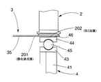
【図4】第2の実施例における無潤滑化のための構成を説明するための説明図である。
【図5】第3の実施例における無潤滑化のための構成を説明するための説明図である。
【符号の説明】
1 波動歯車装置
2 内歯歯車
21 内歯
3 外歯歯車
31 胴部
32 ダイヤフラム
33 ボス
34 外歯
35 胴部内周面
4 波動発生器
41 ウェーブプラグ
42 ウェーブベアリング
43 内輪
44 外輪
45 ボール
46 外輪外周面
47 内輪外周面のボール転動面
48 外輪内周面のボール転動面
101 メッキ皮膜
102 DLC皮膜
103 DLC皮膜
104 皮膜が形成された内周面部分
105 DLC皮膜
201 酸化鉄皮膜
202 DLC皮膜
301、302、303、304 DLC皮膜[0001]
BACKGROUND OF THE INVENTION
The present invention relates to a non-lubricated wave gear device.
[0002]
[Prior art]
A typical wave gear device includes a rigid internal gear having an annular shape, a flexible external gear having an annular shape disposed on the inside thereof, and a wave fitted on the inside of the external gear. It consists of a generator. The wave generator is composed of a rigid wave plug with an elliptical outline and a wave bearing fitted on the outer periphery of the wave plug. The external gear is bent into an elliptical shape at both ends in the major axis direction. The located external tooth part is meshed with the internal tooth part of the rigid internal gear. When the wave generator is rotated by a motor or the like, the meshing position of both gears moves in the circumferential direction. As a result, relative rotation occurs in both gears due to the difference in the number of teeth of both gears. In general, the difference in the number of teeth between the two gears is two, and the internal gear is fixed to the apparatus housing or the like, so that the rotational output greatly reduced based on the difference in the number of teeth is taken out from the external gear.
[0003]
In the wave gear device having this configuration, the lubricant is supplied to the tooth meshing portion of both gears, the friction sliding portion between the external gear and the wave generator, and the friction sliding portion of the wave bearing of the wave generator. I am doing so. For example, JP-A-9-250609, JP-A-9-250610, JP-A-9-250611, etc. propose a lubrication mechanism for these parts.
[0004]
[Problems to be solved by the invention]
However, the lubricant may not be used depending on where the wave gear device is used.
[0005]
Further, for example, when it is necessary to avoid environmental pollution, such as in a clean room, or when used in a vacuum, it is necessary to take measures such as attaching a seal mechanism so that the lubricant does not leak outside.
[0006]
Further, when the operating conditions of the wave gear device are severe, lubrication on the contact surface between the external gear and the wave generator tends to be insufficient. When the contact surface is insufficiently lubricated, heat generation and wear increase due to a large thrust force acting on the contact surface, and problems such as seizure occur.
[0007]
Furthermore, in the frictional sliding portion of the wave bearing attached to the outer periphery of the wave generator in order to make the external gear and the wave generator relatively rotatable, the stirring resistance of the lubricant that lubricates this portion is reduced. Largely, this accounts for a large proportion of the power loss of the wave gear device.
[0008]
In view of these points, an object of the present invention is to propose a wave gear device suitable for use in an environment where the use of a lubricant is not preferable.
[0009]
Another object of the present invention is to propose a wave gear device that can sufficiently lubricate the friction surface between the external gear and the wave generator.
[0010]
Another object of the present invention is to propose a wave gear device capable of avoiding power loss due to agitation resistance of a lubricant that lubricates a wave bearing of a wave generator.
[0011]
[Means for Solving the Problems]
The present invention provides a rigid internal gear having an annular shape, a flexible external gear having an annular shape, and partially engaging the internal gear by bending the external gear in a radial direction. And a wave generator having a wave generator that moves the meshing positions of both gears in the circumferential direction: the internal gear is made of high-strength aluminum alloy or copper alloy; and the external gear is made of structural steel A toothed surface of the internal gear is laminated with a plating film formed by a hard electroless plating process and a DLC film formed by subjecting the surface of the plating film to a DLC coating process; The tooth surface of the toothed gear is characterized in that a DLC film is formed by a low temperature treatment DLC coating.
[0012]
Here, the wave generator generally includes a rigid wave plug, and a wave bearing fitted between the outer peripheral surface of the wave plug and the inner peripheral surface of the external gear, A flexible outer ring whose outer peripheral surface is in contact with the inner peripheral surface of the external gear, an inner ring whose inner peripheral surface is in contact with the outer peripheral surface of the wave plug, and rolling between these outer ring and inner ring And a plurality of rolling elements inserted freely.
[0013]
In this case, the outer ring of the wave generator is composed of SUJ2, and the outer peripheral surface of the external gear has an oxide film formed by steam treatment , an iron sulfide film formed by sulfurization treatment, or a nitridation treatment and It is desirable that an iron oxide film formed by steam treatment is formed, and a DLC film formed by DLC coating treatment is formed on the outer peripheral surface of the outer ring.
[0014]
Further, the rolling element of the wave generator is made of ceramic or SUJ2 , and the inner ring of the wave generator is made of SUJ2 or ceramic , and the rolling surface formed on the inner peripheral surface of the outer ring is DLC coated. A DLC film is formed by treatment, a DLC film by DLC coating is formed on the rolling surface formed on the outer peripheral surface of the inner ring, and a DLC film by DLC coating is formed on the surface of the rolling element. Is preferably formed.
[0015]
Further, the wave plug is preferably made of an aluminum alloy or a copper alloy.
[0019]
DETAILED DESCRIPTION OF THE INVENTION
A non-lubricated wave gear device to which the present invention is applied will be described below with reference to the drawings.
[0020]
1 and 2 are a longitudinal sectional view and a front view showing an example of a cup-type wave gear device to which the present invention can be applied. As shown in these drawings, a cup-shaped
[0021]
The cup-shaped
[0022]
The
[0023]
The
[0024]
(First embodiment)
In the cup-type
[0025]
Referring to FIG. 3, in this example, the
[0026]
Further, the
[0027]
Further, the
[0028]
(Second embodiment)
In the
[0029]
In this example, the
[0030]
Here, in the case of the
[0031]
Similar effects can be obtained by forming a sulfide film by low-temperature sulfuration treatment instead of steam treatment.
[0032]
As materials for the
[0033]
(Third embodiment)
In the
[0034]
The
[0035]
On the outer
[0036]
Here, when SUJ2 is used, since the tempering temperature is low, it is desirable that the DLC coating processing temperature is 100 degrees Celsius or less. Also, many ordinary DLC films have a hardness of about Hv 1000 to 1500. When a DLC film having a higher hardness, for example, about Hv 2000 to 8000, is formed, it is desirable that the surface portion of the member to be coated be soft-nitrided so that the surface layer portion is a gradient material.
[0037]
As described above, the outer ring inner and outer
[0038]
(Fourth embodiment)
Here, according to the experiments by the present inventors, the characteristics required for each part of the wave gear device are as follows.
[0039]
That is, the rigid internal gear as a whole is required to have predetermined rigidity, thermal conductivity, processing accuracy, and fastening strength, and the internal tooth portion of the rigid internal gear is required to have predetermined wear resistance and low friction. It is required to have a coefficient, and it is desirable to have adhesion.
[0040]
The flexible external gear as a whole is required to have predetermined fatigue strength, processing accuracy, wear resistance and fastening strength, and the external tooth portion of the flexible external gear is required to have predetermined wear resistance. At the same time, it is required to have a low coefficient of friction, and it is also desirable to have adhesion. Furthermore, the inner peripheral surface of the flexible internal gear is required to have a low coefficient of friction, wear resistance, and desirably have adhesion.
[0041]
The wave generator is required to have low heat generation, high rolling fatigue strength, and wear resistance.
[0042]
From this point of view, when an unlubricated wave gear device was manufactured under the following conditions, good results were obtained.
[0043]
The rigid internal gear was made of an aluminum alloy, an electroless plating film of 10 μm was formed on the entire surface, and a DLC film of 1 μm or less was formed on the surface of the internal tooth part. This DLC film was formed at a treatment temperature of 350 to 450 ° C. in consideration of the adhesion to the plating film and the gradient of hardness.
[0044]
A flexible external gear was manufactured from stainless steel, a DLC film of 1 μm or less was formed on the surface of the external tooth portion, and the inner peripheral surface thereof was homogenized by diffusion annealing. The DLC film was formed at a processing temperature of 100 ° C. or lower for the purpose of lowering the residual stress.
[0045]
The wave generator was made of an aluminum alloy, the outer ring of the wave bearing was stainless steel, and a DLC film of 1 μm or less was formed on the outer peripheral surface and the inner raceway surface. The ball was made of ceramic. The inner ring was made of stainless steel, and a DLC film of 1 μm or less was formed on the raceway surface portion. The DLC film formed on the outer peripheral surface of the outer ring and the raceway surface portions of the outer ring and the inner ring was formed at a processing temperature of 200 ° C. or lower which is lower than the return temperature of the material.
[0046]
【The invention's effect】
As described above, in the wave gear device of the present invention, the internal gear is made of high-strength aluminum alloy or copper alloy, the external gear is made of structural steel or stainless steel, and the tooth surface of the internal gear is A plating film formed by hard electroless plating and a DLC film formed by DLC coating treatment on the surface of the plating film are laminated, and the tooth surface of the external gear is subjected to low-temperature treatment DLC coating. A DLC film is formed. According to the present invention, it is possible to realize non-lubrication of the tooth surface meshing portion of the internal gear and the external gear.
[0047]
Further, in the wave gear device of the present invention, the outer ring of the wave generator is made of SUJ2, stainless steel or beryllium copper, and the inner peripheral surface of the external gear is formed by an oxide film formed by steam treatment and DLC coating treatment. The formed DLC film, the iron sulfide film formed by the sulfidation process, or the iron oxide film formed by the nitriding process and the steam process is formed, and the DLC film formed by the DLC coating process is formed on the outer peripheral surface of the outer ring. ing. According to this configuration, non-lubrication of the frictional contact portion between the external gear and the wave generator can be realized.
[0048]
Further, in the wave gear device of the present invention, the rolling element of the wave bearing of the wave generator is made of ceramic, stainless steel or SUJ2, and the inner ring is made of SUJ2, stainless steel, beryllium copper or ceramic, and the outer ring. A DLC film formed by DLC coating treatment is formed on the rolling surface formed on the inner peripheral surface of the inner ring, and a DLC coating formed by DLC coating treatment is formed on the rolling surface formed on the outer peripheral surface of the inner ring. A DLC film is formed on the surface of the rolling element by a DLC coating process. According to this configuration, the wave bearing can be made non-lubricated. In addition, when oil-lubricating this wave bearing part, the agitation resistance of the lubricant occupies the majority of the power loss rate of the wave gear device. The advantage that it can be reduced to the above is obtained.
[0049]
Further, if the wave plug is formed of an aluminum alloy or a copper alloy having good thermal conductivity, heat generated on the wave bearing rolling surface can be efficiently discharged to the outside.
[Brief description of the drawings]
FIG. 1 is a longitudinal sectional view showing a cup-type wave gear device to which the present invention is applicable.
2 is a front view of the wave gear device of FIG. 1. FIG.
FIG. 3 is an explanatory diagram for explaining a configuration for non-lubricating in the first embodiment.
FIG. 4 is an explanatory diagram for explaining a configuration for non-lubricating in the second embodiment.
FIG. 5 is an explanatory diagram for explaining a configuration for non-lubrication in a third embodiment.
[Explanation of symbols]
DESCRIPTION OF
Claims (9)
前記内歯歯車は高強度アルミニウム合金または銅合金からなり、
前記外歯歯車は構造用鋼からなり、
前記内歯歯車の歯面には、硬質無電解メッキ処理により形成されたメッキ皮膜と、このメッキ皮膜の表面をDLCコーティング処理することにより形成されたDLC皮膜が積層されており、
前記外歯歯車の歯面には、低温処理DLCコーティングによるDLC皮膜が形成されていることを特徴とする波動歯車装置。A rigid internal gear having an annular shape, a flexible external gear having an annular shape, and the external gear being bent in the radial direction and partially meshed with the internal gear, and both gears. A wave gear device having a wave generator for moving the meshing position of
The internal gear is made of high-strength aluminum alloy or copper alloy,
The external gear is made of structural steel ,
On the tooth surface of the internal gear, a plating film formed by a hard electroless plating process and a DLC film formed by subjecting the surface of the plating film to a DLC coating process are laminated.
A wave gear device, wherein a tooth surface of the external gear has a DLC film formed by low-temperature treatment DLC coating.
前記外歯歯車は構造用鋼からなり、
前記波動発生器は、剛性のウェーブプラグと、このウェーブプラグの外周面および前記外歯歯車の内周面の間に嵌め込まれているウェーブベアリングとを備え、このウェーブベアリングは、外周面が前記外歯歯車の内周面に接触している可撓性の外輪と、内周面が前記ウェーブプラグの外周面に接触している内輪と、これら外輪および内輪の間に転動自在に挿入されている複数個の転動体とを備えており、
前記波動発生器の前記外輪はSUJ2からなり、
前記外歯歯車の内周面には、水蒸気処理により形成した酸化皮膜、浸硫処理により形成した硫化鉄皮膜、あるいは窒化処理および水蒸気処理により形成した酸化鉄皮膜が形成されており、
前記外輪の外周面にはDLCコーティング処理により形成したDLC皮膜が形成されていることを特徴とする波動歯車装置。A rigid internal gear having an annular shape, a flexible external gear having an annular shape, and the external gear being bent in the radial direction and partially meshed with the internal gear, and both gears. A wave gear device having a wave generator for moving the meshing position of
The external gear is made of structural steel ,
The wave generator includes a rigid wave plug and a wave bearing fitted between the outer peripheral surface of the wave plug and the inner peripheral surface of the external gear, and the outer surface of the wave bearing is the outer surface. A flexible outer ring that is in contact with the inner peripheral surface of the toothed gear, an inner ring whose inner peripheral surface is in contact with the outer peripheral surface of the wave plug, and a rollable insert between these outer ring and inner ring. A plurality of rolling elements,
The outer ring of the wave generator is composed of SUJ2 ,
On the inner peripheral surface of the external gear, an oxide film formed by steam treatment , an iron sulfide film formed by sulfurization treatment, or an iron oxide film formed by nitriding treatment and steam treatment is formed,
A wave gear device characterized in that a DLC film formed by a DLC coating process is formed on the outer peripheral surface of the outer ring.
前記波動発生器の前記外輪はSUJ2からなり、
前記波動発生器の前記転動体は、セラミックあるいはSUJ2からなり、
前記波動発生器の内輪は、SUJ2あるいはセラミックからなり、
前記外輪の外周面にはDLCコーティング処理により形成したDLC皮膜が形成されており、
前記外輪の内周面に形成されている転動面にはDLCコーティング処理によるDLC皮膜が形成されており、
前記内輪の外周面に形成されている転動面にはDLCコーティング処理によるDLC皮膜が形成されており、
前記転動体の表面にはDLCコーティング処理によるDLC皮膜が形成されていることを特徴とする波動歯車装置。 In claim 2,
The outer ring of the wave generator is composed of SUJ2 ,
The rolling element of the wave generator is made of ceramic or SUJ2 ,
The inner ring of the wave generator is made of SUJ2 or ceramic ,
A DLC film formed by a DLC coating process is formed on the outer peripheral surface of the outer ring,
A DLC film formed by DLC coating is formed on the rolling surface formed on the inner peripheral surface of the outer ring,
A DLC film formed by DLC coating is formed on the rolling surface formed on the outer peripheral surface of the inner ring,
A wave gear device, wherein a surface of the rolling element has a DLC film formed by a DLC coating process.
前記ウェーブプラグはアルミニウム合金あるいは銅合金からなることを特徴とする波動歯車装置。In claim 3,
The wave plug is made of an aluminum alloy or a copper alloy.
前記内歯歯車は高強度アルミニウム合金または銅合金からなり、
前記外歯歯車は構造用鋼からなり、
前記内歯歯車の歯面には、硬質無電解メッキ処理により形成されたメッキ皮膜と、このメッキ皮膜の表面をDLCコーティング処理することにより形成されたDLC皮膜が積層されており、
前記外歯歯車の歯面には、低温処理DLCコーティングによるDLC皮膜が形成されており、
前記波動発生器は、剛性のウェーブプラグと、このウェーブプラグの外周面および前記外歯歯車の内周面の間に嵌め込まれているウェーブベアリングとを備え、このウェーブベアリングは、外周面が前記外歯歯車の内周面に接触している可撓性の外輪と、内周面が前記ウェーブプラグの外周面に接触している内輪と、これら外輪および内輪の間に転動自在に挿入されている複数個の転動体とを備えており、
前記波動発生器の前記外輪はSUJ2からなり、
前記外歯歯車の内周面には、水蒸気処理により形成した酸化皮膜、浸硫処理により形成した硫化鉄皮膜、あるいは窒化処理および水蒸気処理により形成した酸化鉄皮膜が形成されており、
前記外輪の外周面にはDLCコーティング処理により形成したDLC皮膜が形成されていることを特徴とする波動歯車装置。 A rigid internal gear having an annular shape, a flexible external gear having an annular shape, and the external gear being bent in the radial direction and partially meshed with the internal gear, and both gears. A wave gear device having a wave generator for moving the meshing position of
The internal gear is made of high-strength aluminum alloy or copper alloy,
The external gear is made of structural steel,
On the tooth surface of the internal gear, a plating film formed by a hard electroless plating process and a DLC film formed by subjecting the surface of the plating film to a DLC coating process are laminated.
On the tooth surface of the external gear, a DLC film is formed by low temperature treatment DLC coating,
The wave generator includes a rigid wave plug and a wave bearing fitted between the outer peripheral surface of the wave plug and the inner peripheral surface of the external gear, and the outer surface of the wave bearing is the outer surface. A flexible outer ring that is in contact with the inner peripheral surface of the toothed gear, an inner ring whose inner peripheral surface is in contact with the outer peripheral surface of the wave plug, and a rollable insert between these outer ring and inner ring. A plurality of rolling elements,
The outer ring of the wave generator is composed of SUJ2 ,
On the inner peripheral surface of the external gear, an oxide film formed by steam treatment , an iron sulfide film formed by sulfurization treatment, or an iron oxide film formed by nitriding treatment and steam treatment is formed,
A wave gear device characterized in that a DLC film formed by a DLC coating process is formed on the outer peripheral surface of the outer ring.
前記波動発生器の前記転動体は、セラミックあるいはSUJ2からなり、
前記波動発生器の内輪は、SUJ2あるいはセラミックからなり、
前記外輪の内周面に形成されている転動面にはDLCコーティング処理によるDLC皮膜が形成されており、
前記内輪の外周面に形成されている転動面にはDLCコーティング処理によるDLC皮膜が形成されており、
前記転動体の表面にはDLCコーティング処理によるDLC皮膜が形成されていることを特徴とする波動歯車装置。In claim 5,
The rolling element of the wave generator is made of ceramic or SUJ2 ,
The inner ring of the wave generator is made of SUJ2 or ceramic ,
A DLC film formed by DLC coating is formed on the rolling surface formed on the inner peripheral surface of the outer ring,
A DLC film formed by DLC coating is formed on the rolling surface formed on the outer peripheral surface of the inner ring,
A wave gear device, wherein a surface of the rolling element has a DLC film formed by a DLC coating process.
前記ウェーブプラグはアルミニウム合金あるいは銅合金からなることを特徴とする波動歯車装置。In claim 6,
The wave plug is made of an aluminum alloy or a copper alloy.
前記波動発生器は、剛性のウェーブプラグと、このウェーブプラグの外周面および前記外歯歯車の内周面の間に嵌め込まれているウェーブベアリングとを備え、このウェーブベアリングは、外周面が前記外歯歯車の内周面に接触している可撓性の外輪と、内周面が前記ウェーブプラグの外周面に接触している内輪と、これら外輪および内輪の間に転動自在に挿入されている複数個の転動体とを備えており、
前記波動発生器の前記外輪はSUJ2からなり、
前記波動発生器の前記転動体は、セラミックあるいはSUJ2からなり、
前記波動発生器の内輪は、SUJ2あるいはセラミックからなり、
前記外輪の外周面にはDLCコーティング処理により形成したDLC皮膜が形成されており、
前記外輪の内周面に形成されている転動面にはDLCコーティング処理によるDLC皮膜が形成されており、
前記内輪の外周面に形成されている転動面にはDLCコーティング処理によるDLC皮膜が形成されており、
前記転動体の表面にはDLCコーティング処理によるDLC皮膜が形成されていることを特徴とする波動歯車装置。In claim 1,
The wave generator includes a rigid wave plug and a wave bearing fitted between the outer peripheral surface of the wave plug and the inner peripheral surface of the external gear, and the outer surface of the wave bearing is the outer surface. A flexible outer ring that is in contact with the inner peripheral surface of the toothed gear, an inner ring whose inner peripheral surface is in contact with the outer peripheral surface of the wave plug, and a rollable insert between these outer ring and inner ring. A plurality of rolling elements,
The outer ring of the wave generator is composed of SUJ2 ,
The rolling element of the wave generator is made of ceramic or SUJ2 ,
The inner ring of the wave generator is made of SUJ2 or ceramic ,
A DLC film formed by a DLC coating process is formed on the outer peripheral surface of the outer ring,
A DLC film formed by DLC coating is formed on the rolling surface formed on the inner peripheral surface of the outer ring,
A DLC film formed by DLC coating is formed on the rolling surface formed on the outer peripheral surface of the inner ring,
A wave gear device, wherein a surface of the rolling element has a DLC film formed by a DLC coating process.
前記ウェーブプラグはアルミニウム合金あるいは銅合金からなることを特徴とする波動歯車装置。In claim 8,
The wave plug is made of an aluminum alloy or a copper alloy.
Priority Applications (3)
| Application Number | Priority Date | Filing Date | Title |
|---|---|---|---|
| JP2001154330A JP4807689B2 (en) | 2001-05-23 | 2001-05-23 | Lubrication-type wave gear device |
| US10/146,928 US6615689B2 (en) | 2001-05-23 | 2002-05-17 | Non-lubricated wave gear device |
| DE10222695.4A DE10222695B4 (en) | 2001-05-23 | 2002-05-22 | Lubricationless shaft gear device |
Applications Claiming Priority (1)
| Application Number | Priority Date | Filing Date | Title |
|---|---|---|---|
| JP2001154330A JP4807689B2 (en) | 2001-05-23 | 2001-05-23 | Lubrication-type wave gear device |
Publications (2)
| Publication Number | Publication Date |
|---|---|
| JP2002349645A JP2002349645A (en) | 2002-12-04 |
| JP4807689B2 true JP4807689B2 (en) | 2011-11-02 |
Family
ID=18998686
Family Applications (1)
| Application Number | Title | Priority Date | Filing Date |
|---|---|---|---|
| JP2001154330A Expired - Lifetime JP4807689B2 (en) | 2001-05-23 | 2001-05-23 | Lubrication-type wave gear device |
Country Status (3)
| Country | Link |
|---|---|
| US (1) | US6615689B2 (en) |
| JP (1) | JP4807689B2 (en) |
| DE (1) | DE10222695B4 (en) |
Cited By (1)
| Publication number | Priority date | Publication date | Assignee | Title |
|---|---|---|---|---|
| WO2019155831A1 (en) | 2018-02-07 | 2019-08-15 | 株式会社ハーモニック・ドライブ・システムズ | Wave gear device |
Families Citing this family (48)
| Publication number | Priority date | Publication date | Assignee | Title |
|---|---|---|---|---|
| DE20306004U1 (en) | 2003-04-15 | 2003-07-03 | AB SKF, Göteborg/Gotenburg | Sealed rolling element bearing, for e.g. fuel pump, includes running surfaces with wear-resistant coating lubricated by grease which is not soluble in fuel |
| DE10351258B4 (en) * | 2003-11-03 | 2005-10-27 | Metabowerke Gmbh | On power transmission claimed transmission part |
| DE102004009128A1 (en) | 2004-02-25 | 2005-09-15 | Ina-Schaeffler Kg | Electric camshaft adjuster |
| US20050188800A1 (en) * | 2004-02-26 | 2005-09-01 | Springs Window Fashions Lp | Louver clip and method of use |
| WO2005100818A1 (en) * | 2004-04-15 | 2005-10-27 | Harmonic Drive Systems Inc. | Wave gear device |
| DE102004024965B3 (en) * | 2004-05-21 | 2005-11-24 | Schwachenwalde, Bernd, Dr.-Ing. | Gear mechanism for adjusting vehicle seat, especially motor vehicle seat, has second ring with second collar on inner casing that engages first collar and eccentrically engages groove to hold fittings together in desired mounting position |
| US7296965B2 (en) * | 2004-08-23 | 2007-11-20 | United Technologies Corporation | Cryogenic bearings |
| JP2007119898A (en) * | 2005-09-27 | 2007-05-17 | Toyota Motor Corp | Sliding member |
| JP2007106058A (en) * | 2005-10-17 | 2007-04-26 | Fujifilm Corp | Mold for molding |
| DE102005062305A1 (en) * | 2005-12-24 | 2007-07-05 | Maschinen Witte Gmbh & Co. Kg | Cutting table and method for cutting profile sections |
| JP4902227B2 (en) * | 2006-03-01 | 2012-03-21 | 本田技研工業株式会社 | Wave gear device |
| ATE471571T1 (en) * | 2006-03-23 | 2010-07-15 | Timken Co | SURFACE TREATMENTS FOR SPIRAL AND BEVELED GEAR UNITS |
| US7718044B2 (en) * | 2006-09-11 | 2010-05-18 | Seagate Technology Llc | Method for controlling shaft coating taper |
| EP1997937A1 (en) * | 2007-05-21 | 2008-12-03 | NV Bekaert SA | Aluminium gear with hard carbon coating |
| JP4897610B2 (en) * | 2007-08-08 | 2012-03-14 | 株式会社ハーモニック・ドライブ・システムズ | Wave generator, wave gear device, and efficiency reduction prevention method for wave gear device |
| JP5178542B2 (en) * | 2009-01-13 | 2013-04-10 | 株式会社ハーモニック・ドライブ・システムズ | Wave generator of wave gear device |
| JP5467019B2 (en) | 2010-09-07 | 2014-04-09 | 住友重機械工業株式会社 | Bending gear system |
| DE102011004077A1 (en) | 2011-02-14 | 2012-08-16 | Schaeffler Technologies Gmbh & Co. Kg | Harmonic drive used as electromechanical camshaft phaser for three-wave system, has wave generator having ring with elliptical outer periphery mounted on outer periphery of bearing, and axial spacing is formed between ring gears |
| DE102011004066A1 (en) * | 2011-02-14 | 2012-08-16 | Schaeffler Technologies Gmbh & Co. Kg | 3-shaft variable speed gearbox and method of manufacturing a wave generator |
| DE102011004074A1 (en) | 2011-02-14 | 2012-08-16 | Schaeffler Technologies Gmbh & Co. Kg | Wave gear with stiffness-optimized wave generator |
| DE102011004075A1 (en) | 2011-02-14 | 2012-08-16 | Schaeffler Technologies Gmbh & Co. Kg | Wave gear with lateral guidance of the spur gear |
| WO2013175531A1 (en) * | 2012-05-23 | 2013-11-28 | 株式会社ハーモニック・ドライブ・システムズ | Strain wave gear device and flexible external gear |
| JP6027481B2 (en) * | 2013-03-29 | 2016-11-16 | 住友重機械工業株式会社 | Bending gear system |
| WO2014181375A1 (en) * | 2013-05-08 | 2014-11-13 | 株式会社ハーモニック・ドライブ・システムズ | Wave generator of strain wave gear device |
| KR101933435B1 (en) * | 2014-11-28 | 2018-12-28 | 가부시키가이샤 하모닉 드라이브 시스템즈 | Method for lubricating strain wave gearing |
| DE102015104135A1 (en) | 2015-03-19 | 2016-09-22 | Harmonic Drive Ag | Wave gear with dry running |
| WO2019100085A1 (en) | 2017-11-14 | 2019-05-23 | Synventive Molding Solutions, Inc. | Actuator with eccentric pin drive |
| CN107559403B (en) * | 2016-06-30 | 2020-05-19 | 比亚迪股份有限公司 | A kind of harmonic reducer flexible wheel and its manufacturing method |
| JP2018017317A (en) | 2016-07-28 | 2018-02-01 | セイコーエプソン株式会社 | Robot, gear device, and manufacturing method of gear device |
| US10451174B2 (en) * | 2016-07-29 | 2019-10-22 | Seiko Epson Corporation | Robot and gear device |
| JP6552745B2 (en) | 2016-07-30 | 2019-07-31 | 株式会社ハーモニック・ドライブ・システムズ | Wave generator and wave gear device |
| EP3492774B1 (en) * | 2016-07-30 | 2020-09-23 | Harmonic Drive Systems Inc. | Wave generator, and wave gear device |
| DE102016216802B3 (en) * | 2016-09-06 | 2018-02-01 | Schaeffler Technologies AG & Co. KG | Drive device for a motor vehicle |
| JP6808474B2 (en) * | 2016-12-19 | 2021-01-06 | 株式会社ハーモニック・ドライブ・システムズ | Absolute encoder for motor with gear |
| CN111051733A (en) * | 2017-09-07 | 2020-04-21 | 谐波传动系统有限公司 | The pulsator bearing of the wave gear unit |
| JP6695649B2 (en) * | 2017-10-19 | 2020-05-20 | 株式会社ハーモニック・ドライブ・システムズ | Wave gearing having three-dimensional meshing tooth profile |
| EP3827958A1 (en) | 2017-12-22 | 2021-06-02 | Synventive Molding Solutions, Inc. | Actuator with eccentric pin drive |
| US11725719B2 (en) * | 2018-08-10 | 2023-08-15 | Sony Corporation | Gear wheel mechanism and manufacturing method for a gear wheel mechanism |
| JP7426774B2 (en) * | 2018-10-22 | 2024-02-02 | 住友重機械工業株式会社 | Flexible mesh gear device and its manufacturing method |
| US10801608B2 (en) * | 2018-10-31 | 2020-10-13 | Hiwin Technologies Corp. | Harmonic reducer with an oil guiding ring |
| JP7221077B2 (en) * | 2019-02-20 | 2023-02-13 | 住友重機械工業株式会社 | Flexible mesh gear device and manufacturing method thereof |
| JP7598701B2 (en) * | 2019-04-26 | 2024-12-12 | 株式会社ジェイテクト | Rolling bearings |
| JP2021196038A (en) * | 2020-06-17 | 2021-12-27 | 住友重機械工業株式会社 | Gear device |
| JP7641713B2 (en) * | 2020-08-12 | 2025-03-07 | 住友重機械工業株式会社 | Flexible mesh gear device and manufacturing method thereof |
| CN114262868A (en) * | 2021-12-03 | 2022-04-01 | 中船重工重庆液压机电有限公司 | Surface DLC coating bonding method for copper alloy outer shim |
| JP7518811B2 (en) * | 2021-12-24 | 2024-07-18 | 美的集団股▲フン▼有限公司 | Harmonic gear device and robot joint device |
| CN118208527A (en) * | 2022-12-16 | 2024-06-18 | 美的集团股份有限公司 | Gear device and method for manufacturing gear device |
| DE102023212648A1 (en) * | 2023-12-14 | 2025-06-18 | Zf Friedrichshafen Ag | Gear assembly and wave gear with a gear assembly |
Family Cites Families (18)
| Publication number | Priority date | Publication date | Assignee | Title |
|---|---|---|---|---|
| JPS5835562B2 (en) * | 1979-07-28 | 1983-08-03 | 日産自動車株式会社 | Automotive cam timing pulley and its manufacturing method |
| FR2599108B1 (en) * | 1986-05-22 | 1990-08-17 | Alcatel Espace | LARGE TRAVEL DRIVE MECHANISM FOR VACUUM USE COMPRISING A REDUCER WHICH HAS BEEN DRIVEN LUBRICATION TREATMENTS |
| US5288556A (en) * | 1987-03-31 | 1994-02-22 | Lemelson Jerome H | Gears and gear assemblies |
| JPH02275166A (en) * | 1989-04-13 | 1990-11-09 | Harmonic Drive Syst Ind Co Ltd | Wave motion gear device |
| US5482602A (en) * | 1993-11-04 | 1996-01-09 | United Technologies Corporation | Broad-beam ion deposition coating methods for depositing diamond-like-carbon coatings on dynamic surfaces |
| JP3835709B2 (en) * | 1996-03-18 | 2006-10-18 | 株式会社ハーモニック・ドライブ・システムズ | Lubrication mechanism of flexibly meshing gear system |
| JP3781314B2 (en) | 1996-03-18 | 2006-05-31 | 株式会社ハーモニック・ドライブ・システムズ | Lubrication mechanism of flexibly meshing gear system |
| JP3781312B2 (en) | 1996-03-18 | 2006-05-31 | 株式会社ハーモニック・ドライブ・システムズ | Lubrication mechanism of flexure mesh gear system |
| JPH09259611A (en) | 1996-03-22 | 1997-10-03 | Matsushita Electric Ind Co Ltd | Tunnel lighting |
| JP3788527B2 (en) * | 1996-05-17 | 2006-06-21 | 株式会社ハーモニック・ドライブ・システムズ | Method for forming coating on teeth of flexible meshing gear device |
| JPH1019092A (en) * | 1996-07-03 | 1998-01-20 | Harmonic Drive Syst Ind Co Ltd | Wear prevention mechanism for flexible meshing gear units |
| JP3912848B2 (en) * | 1997-05-23 | 2007-05-09 | 株式会社ハーモニック・ドライブ・システムズ | Flexure meshing gear unit |
| US6082222A (en) * | 1997-10-27 | 2000-07-04 | Harmonic Drive Systems, Inc. | Rigid internal gear of a wave gear drive |
| JP4155420B2 (en) * | 1997-10-31 | 2008-09-24 | 株式会社ハーモニック・ドライブ・システムズ | Wave generator with Oldham function of flexure meshing gear system |
| JP2000002315A (en) * | 1998-06-15 | 2000-01-07 | Nissan Motor Co Ltd | High surface pressure gear and manufacturing method thereof |
| JP3761731B2 (en) * | 1999-01-19 | 2006-03-29 | 株式会社ジェイテクト | Rolling bearing |
| JP2000219427A (en) * | 1999-01-28 | 2000-08-08 | Toray Ind Inc | Yarn traverse device |
| JP2001254789A (en) * | 2000-03-10 | 2001-09-21 | Yaskawa Electric Corp | Rotary stage |
-
2001
- 2001-05-23 JP JP2001154330A patent/JP4807689B2/en not_active Expired - Lifetime
-
2002
- 2002-05-17 US US10/146,928 patent/US6615689B2/en not_active Expired - Lifetime
- 2002-05-22 DE DE10222695.4A patent/DE10222695B4/en not_active Expired - Lifetime
Cited By (2)
| Publication number | Priority date | Publication date | Assignee | Title |
|---|---|---|---|---|
| WO2019155831A1 (en) | 2018-02-07 | 2019-08-15 | 株式会社ハーモニック・ドライブ・システムズ | Wave gear device |
| US11015693B2 (en) | 2018-02-07 | 2021-05-25 | Harmonic Drive Systems Inc. | Wave gear device |
Also Published As
| Publication number | Publication date |
|---|---|
| JP2002349645A (en) | 2002-12-04 |
| US20020174741A1 (en) | 2002-11-28 |
| DE10222695B4 (en) | 2015-09-24 |
| US6615689B2 (en) | 2003-09-09 |
| DE10222695A1 (en) | 2003-02-20 |
Similar Documents
| Publication | Publication Date | Title |
|---|---|---|
| JP4807689B2 (en) | Lubrication-type wave gear device | |
| JP2510374B2 (en) | Sliding / rolling bearings with rolling elements | |
| JP2002349681A (en) | Lubrication mechanism of wave gear device | |
| JP2009041747A (en) | Power transmission device and sliding part structure for power transmission device | |
| US11015693B2 (en) | Wave gear device | |
| WO2015060371A1 (en) | Retainer for needle roller bearing, and needle roller bearing | |
| JP2002130409A (en) | Dry type continuously variable transmission | |
| JPH02271106A (en) | Sliding bearing device | |
| JP2008196583A (en) | Tapered roller bearing for planetary roller | |
| JP4017818B2 (en) | Ball bearing | |
| WO2012017860A1 (en) | Roller and cage assembly, roller bearing and cage assembly, and cage | |
| JPH1019092A (en) | Wear prevention mechanism for flexible meshing gear units | |
| JP2009250342A (en) | Constant velocity universal joint | |
| JP2004332899A (en) | Solid lubricated rolling bearing | |
| JP7520474B2 (en) | Rolling bearings and wave gear devices for space applications | |
| JP3728491B2 (en) | Cam follower | |
| JP2006090402A (en) | Rotating support device for turbocharger | |
| JP3811596B2 (en) | Rolling motion parts | |
| JP7163466B1 (en) | Strain wave gearing | |
| JP2002235834A (en) | Gear box and continuously variable transmission | |
| JP2007255607A (en) | Wave gear device | |
| JP2018194094A (en) | Robot, gear unit, and method of manufacturing the gear unit | |
| CN103270336B (en) | Gear drive | |
| WO2018143138A1 (en) | Rolling bearing | |
| WO1997013077A1 (en) | End bearing for a one-way clutch |
Legal Events
| Date | Code | Title | Description |
|---|---|---|---|
| A711 | Notification of change in applicant |
Free format text: JAPANESE INTERMEDIATE CODE: A711 Effective date: 20040618 |
|
| A521 | Request for written amendment filed |
Free format text: JAPANESE INTERMEDIATE CODE: A821 Effective date: 20040618 |
|
| A621 | Written request for application examination |
Free format text: JAPANESE INTERMEDIATE CODE: A621 Effective date: 20080205 |
|
| A977 | Report on retrieval |
Free format text: JAPANESE INTERMEDIATE CODE: A971007 Effective date: 20101125 |
|
| A131 | Notification of reasons for refusal |
Free format text: JAPANESE INTERMEDIATE CODE: A131 Effective date: 20101130 |
|
| A521 | Request for written amendment filed |
Free format text: JAPANESE INTERMEDIATE CODE: A523 Effective date: 20110216 |
|
| TRDD | Decision of grant or rejection written | ||
| A01 | Written decision to grant a patent or to grant a registration (utility model) |
Free format text: JAPANESE INTERMEDIATE CODE: A01 Effective date: 20110809 |
|
| A01 | Written decision to grant a patent or to grant a registration (utility model) |
Free format text: JAPANESE INTERMEDIATE CODE: A01 |
|
| A61 | First payment of annual fees (during grant procedure) |
Free format text: JAPANESE INTERMEDIATE CODE: A61 Effective date: 20110809 |
|
| FPAY | Renewal fee payment (event date is renewal date of database) |
Free format text: PAYMENT UNTIL: 20140826 Year of fee payment: 3 |
|
| R150 | Certificate of patent or registration of utility model |
Ref document number: 4807689 Country of ref document: JP Free format text: JAPANESE INTERMEDIATE CODE: R150 Free format text: JAPANESE INTERMEDIATE CODE: R150 |
|
| R250 | Receipt of annual fees |
Free format text: JAPANESE INTERMEDIATE CODE: R250 |
|
| R250 | Receipt of annual fees |
Free format text: JAPANESE INTERMEDIATE CODE: R250 |
|
| R250 | Receipt of annual fees |
Free format text: JAPANESE INTERMEDIATE CODE: R250 |
|
| R250 | Receipt of annual fees |
Free format text: JAPANESE INTERMEDIATE CODE: R250 |
|
| R250 | Receipt of annual fees |
Free format text: JAPANESE INTERMEDIATE CODE: R250 |
|
| R250 | Receipt of annual fees |
Free format text: JAPANESE INTERMEDIATE CODE: R250 |
|
| R250 | Receipt of annual fees |
Free format text: JAPANESE INTERMEDIATE CODE: R250 |
|
| EXPY | Cancellation because of completion of term |