JP4772569B2 - System and method for performing directory unit migration in a common namespace - Google Patents
System and method for performing directory unit migration in a common namespace Download PDFInfo
- Publication number
- JP4772569B2 JP4772569B2 JP2006106255A JP2006106255A JP4772569B2 JP 4772569 B2 JP4772569 B2 JP 4772569B2 JP 2006106255 A JP2006106255 A JP 2006106255A JP 2006106255 A JP2006106255 A JP 2006106255A JP 4772569 B2 JP4772569 B2 JP 4772569B2
- Authority
- JP
- Japan
- Prior art keywords
- file
- server
- file system
- directory
- identifier
- Prior art date
- Legal status (The legal status is an assumption and is not a legal conclusion. Google has not performed a legal analysis and makes no representation as to the accuracy of the status listed.)
- Expired - Fee Related
Links
Images
Classifications
-
- G—PHYSICS
- G06—COMPUTING OR CALCULATING; COUNTING
- G06F—ELECTRIC DIGITAL DATA PROCESSING
- G06F3/00—Input arrangements for transferring data to be processed into a form capable of being handled by the computer; Output arrangements for transferring data from processing unit to output unit, e.g. interface arrangements
- G06F3/06—Digital input from, or digital output to, record carriers, e.g. RAID, emulated record carriers or networked record carriers
- G06F3/0601—Interfaces specially adapted for storage systems
- G06F3/0628—Interfaces specially adapted for storage systems making use of a particular technique
- G06F3/0646—Horizontal data movement in storage systems, i.e. moving data in between storage devices or systems
- G06F3/0647—Migration mechanisms
-
- G—PHYSICS
- G06—COMPUTING OR CALCULATING; COUNTING
- G06F—ELECTRIC DIGITAL DATA PROCESSING
- G06F16/00—Information retrieval; Database structures therefor; File system structures therefor
- G06F16/10—File systems; File servers
- G06F16/11—File system administration, e.g. details of archiving or snapshots
- G06F16/119—Details of migration of file systems
-
- G—PHYSICS
- G06—COMPUTING OR CALCULATING; COUNTING
- G06F—ELECTRIC DIGITAL DATA PROCESSING
- G06F3/00—Input arrangements for transferring data to be processed into a form capable of being handled by the computer; Output arrangements for transferring data from processing unit to output unit, e.g. interface arrangements
- G06F3/06—Digital input from, or digital output to, record carriers, e.g. RAID, emulated record carriers or networked record carriers
- G06F3/0601—Interfaces specially adapted for storage systems
- G06F3/0602—Interfaces specially adapted for storage systems specifically adapted to achieve a particular effect
- G06F3/061—Improving I/O performance
-
- G—PHYSICS
- G06—COMPUTING OR CALCULATING; COUNTING
- G06F—ELECTRIC DIGITAL DATA PROCESSING
- G06F3/00—Input arrangements for transferring data to be processed into a form capable of being handled by the computer; Output arrangements for transferring data from processing unit to output unit, e.g. interface arrangements
- G06F3/06—Digital input from, or digital output to, record carriers, e.g. RAID, emulated record carriers or networked record carriers
- G06F3/0601—Interfaces specially adapted for storage systems
- G06F3/0628—Interfaces specially adapted for storage systems making use of a particular technique
- G06F3/0629—Configuration or reconfiguration of storage systems
- G06F3/0635—Configuration or reconfiguration of storage systems by changing the path, e.g. traffic rerouting, path reconfiguration
-
- G—PHYSICS
- G06—COMPUTING OR CALCULATING; COUNTING
- G06F—ELECTRIC DIGITAL DATA PROCESSING
- G06F3/00—Input arrangements for transferring data to be processed into a form capable of being handled by the computer; Output arrangements for transferring data from processing unit to output unit, e.g. interface arrangements
- G06F3/06—Digital input from, or digital output to, record carriers, e.g. RAID, emulated record carriers or networked record carriers
- G06F3/0601—Interfaces specially adapted for storage systems
- G06F3/0628—Interfaces specially adapted for storage systems making use of a particular technique
- G06F3/0638—Organizing or formatting or addressing of data
- G06F3/0643—Management of files
-
- G—PHYSICS
- G06—COMPUTING OR CALCULATING; COUNTING
- G06F—ELECTRIC DIGITAL DATA PROCESSING
- G06F3/00—Input arrangements for transferring data to be processed into a form capable of being handled by the computer; Output arrangements for transferring data from processing unit to output unit, e.g. interface arrangements
- G06F3/06—Digital input from, or digital output to, record carriers, e.g. RAID, emulated record carriers or networked record carriers
- G06F3/0601—Interfaces specially adapted for storage systems
- G06F3/0668—Interfaces specially adapted for storage systems adopting a particular infrastructure
- G06F3/067—Distributed or networked storage systems, e.g. storage area networks [SAN], network attached storage [NAS]
-
- G—PHYSICS
- G06—COMPUTING OR CALCULATING; COUNTING
- G06F—ELECTRIC DIGITAL DATA PROCESSING
- G06F2206/00—Indexing scheme related to dedicated interfaces for computers
- G06F2206/10—Indexing scheme related to storage interfaces for computers, indexing schema related to group G06F3/06
- G06F2206/1012—Load balancing
-
- Y—GENERAL TAGGING OF NEW TECHNOLOGICAL DEVELOPMENTS; GENERAL TAGGING OF CROSS-SECTIONAL TECHNOLOGIES SPANNING OVER SEVERAL SECTIONS OF THE IPC; TECHNICAL SUBJECTS COVERED BY FORMER USPC CROSS-REFERENCE ART COLLECTIONS [XRACs] AND DIGESTS
- Y10—TECHNICAL SUBJECTS COVERED BY FORMER USPC
- Y10S—TECHNICAL SUBJECTS COVERED BY FORMER USPC CROSS-REFERENCE ART COLLECTIONS [XRACs] AND DIGESTS
- Y10S707/00—Data processing: database and file management or data structures
- Y10S707/99931—Database or file accessing
- Y10S707/99932—Access augmentation or optimizing
-
- Y—GENERAL TAGGING OF NEW TECHNOLOGICAL DEVELOPMENTS; GENERAL TAGGING OF CROSS-SECTIONAL TECHNOLOGIES SPANNING OVER SEVERAL SECTIONS OF THE IPC; TECHNICAL SUBJECTS COVERED BY FORMER USPC CROSS-REFERENCE ART COLLECTIONS [XRACs] AND DIGESTS
- Y10—TECHNICAL SUBJECTS COVERED BY FORMER USPC
- Y10S—TECHNICAL SUBJECTS COVERED BY FORMER USPC CROSS-REFERENCE ART COLLECTIONS [XRACs] AND DIGESTS
- Y10S707/00—Data processing: database and file management or data structures
- Y10S707/99951—File or database maintenance
- Y10S707/99956—File allocation
Landscapes
- Engineering & Computer Science (AREA)
- Theoretical Computer Science (AREA)
- Physics & Mathematics (AREA)
- General Engineering & Computer Science (AREA)
- General Physics & Mathematics (AREA)
- Human Computer Interaction (AREA)
- Computer Networks & Wireless Communication (AREA)
- Data Mining & Analysis (AREA)
- Databases & Information Systems (AREA)
- Information Retrieval, Db Structures And Fs Structures Therefor (AREA)
Description
本発明は、ネットワークを介してクライアントと接続され、クライアントが用いるデータを記憶する、ファイルサーバ又はネットワークアタッチドストレージ(Network Attached Storage、NAS)において、複数のサーバに負荷を分散するための技術に関する。 The present invention relates to a technique for distributing a load to a plurality of servers in a file server or network attached storage (NAS) that is connected to a client via a network and stores data used by the client.
ネットワークに接続されたストレージシステムが、そのネットワークに接続されたクライアント計算機の共有ディスクとして使用される、ネットワークアタッチドストレージ(Network Attached Storage、NAS)が提案されている。NASは、ネットワークインターフェース等を含むサーバと、データを格納するディスクドライブとによって構成される。 Network attached storage (NAS), in which a storage system connected to a network is used as a shared disk of a client computer connected to the network, has been proposed. The NAS is composed of a server including a network interface and a disk drive for storing data.
例えば、特許文献1には、複数のサーバを備え、各サーバがネットワークに接続されるクラスタ構成のNASが開示されている。特許文献1に記載されたシステムにおいて、ネットワークエレメント、スイッチングエレメント及びディスクエレメントが、NASのサーバに相当する。特許文献1に記載されたシステムは、ファイルシステムを共有する複数のネットワークエレメントを備えることができる。また、特許文献1に記載されたシステムは、ディスクエレメントを複数備えることによって、ディスク単位でデータをマイグレーションすることができる。さらに、各ネットワークエレメントがディスクエレメントによって管理される全てのファイルシステムにアクセスすることができる。ディスクエレメント間で、ファイルシステムを格納しているディスクのマイグレーションが実行された場合も、各ネットワークエレメントは、マイグレーションによる影響を受けることなく、全てのファイルシステムにアクセスをすることができる。
For example,
ネットワーク上に分散して存在するファイルにアクセスするためのファイルシステムの一つとして、ネットワークファイルシステム(NFS)が提案されている。NFSの現時点の最新版であるNFSv4(RFC3530)(非特許文献1参照)によれば、ファイルシステムがサーバ間でマイグレーションされた場合、サーバは、クライアントからの当該ファイルシステムへのアクセスに対して、マイグレーション先の位置の情報を通知する。この通知を受けたクライアントは、通知された位置情報に従って、マイグレーション先のファイルシステムにアクセスすることができる。
複数のサーバが管理する複数のファイルシステムを、一つの名前空間によってクライアントに提供することができる。そのような名前空間は、グローバルネームスペース(GNS)と呼ばれる。GNSを適用したシステムでは、負荷の高いサーバから負荷の低いサーバへファイルを転送するマイグレーションによって、複数のサーバ間の負荷の均衡を図ることができる。 A plurality of file systems managed by a plurality of servers can be provided to the client by one name space. Such a namespace is called a global namespace (GNS). In a system to which GNS is applied, it is possible to balance the load among a plurality of servers by migration that transfers files from a server with a high load to a server with a low load.
GNSにおいて、負荷均衡のためのマイグレーションをクライアントから透過的に実行するために、ファイルに付与されたID(ファイルハンドル)を維持する必要がある。言い換えると、マイグレーションの前に付与されたファイルハンドルが、マイグレーションの後にも使用できることが必要である。なお、ファイルハンドルは、各サーバが管理するファイルシステムをそのサーバ内で一意に識別するファイルシステムIDと、各ファイルをファイルシステム内で一意に識別するファイルIDとを含む。 In GNS, it is necessary to maintain an ID (file handle) given to a file in order to execute migration for load balancing transparently from a client. In other words, the file handle given before migration must be usable after migration. The file handle includes a file system ID that uniquely identifies a file system managed by each server within the server, and a file ID that uniquely identifies each file within the file system.
ファイルハンドルを維持するために、システム内で一意に定まるファイルシステムIDをファイルシステムに割り振り、ファイルシステム単位でマイグレーションを実行してもよい。この場合、ファイルシステムを管理しているサーバに依存しない、システム内で一意のファイルハンドルが付与される。その結果、クライアントは、自分がアクセスしようとするファイルが、どのサーバによって管理されているファイルシステムに属するかを意識する必要がない。すなわち、ファイルシステムが一つのサーバから別のサーバにマイグレーションされた後も、クライアントは、マイグレーションが実行される前に付与されたファイルハンドルを使用して、そのファイルシステムに属するファイルにアクセスすることができる。このようにして、クライアントから透過的なファイルシステムのマイグレーションが実現される。 In order to maintain the file handle, a file system ID uniquely determined in the system may be allocated to the file system, and migration may be executed in units of file systems. In this case, a file handle that is unique within the system and that does not depend on the server that manages the file system is assigned. As a result, the client does not need to be aware of which server is managing the file system managed by the file to be accessed by the client. That is, even after a file system is migrated from one server to another, the client can access files belonging to that file system using the file handle that was given before the migration was performed. it can. In this way, migration of the file system transparent from the client is realized.
しかし、サーバ間の負荷の均衡を目的としてマイグレーションを行う場合、ファイルシステム単位では粒度が粗いため、十分な負荷均衡が行えない場合がある。例えば、一つのファイルシステムのみに負荷が集中している場合、そのファイルシステム全体をマイグレーションしても、そのファイルシステムの負荷全体が移動するだけである。その結果、負荷を複数のサーバに分散して均衡させることができない。この場合、ファイルシステムより細かい単位で、例えば、ディレクトリ単位でのマイグレーションを実行する必要がある。 However, when migration is performed for the purpose of balancing the load between servers, there is a case where sufficient load balancing cannot be performed because the granularity is coarse in file system units. For example, when the load is concentrated on only one file system, even if the entire file system is migrated, only the entire load of the file system is moved. As a result, the load cannot be distributed and balanced among a plurality of servers. In this case, it is necessary to execute migration in units smaller than the file system, for example, in units of directories.
例えば、あるサーバが管理している任意のファイル又はディレクトリを、別のサーバが管理するファイルシステムにコピーすることによって、ファイルシステムより細かい単位のマイグレーションを実現することができる。その結果、そのファイル等に対するアクセスによる負荷を分散させることによって、複数のサーバの負荷を均衡させることができる。しかし、この場合、クライアントは、マイグレーションの実行前に取得したファイルハンドルを用いて、マイグレーションされたファイルにアクセスすることができない。すなわち、再度名前解決を実行する必要がある。 For example, by copying an arbitrary file or directory managed by a server to a file system managed by another server, it is possible to realize migration in a smaller unit than the file system. As a result, it is possible to balance the load of a plurality of servers by distributing the load due to access to the file or the like. However, in this case, the client cannot access the migrated file using the file handle obtained before the migration is executed. That is, it is necessary to perform name resolution again.
ファイルシステムよりも細かい単位で、クライアントから透過的なマイグレーションを実行する方法については、開示されていない。 A method for performing transparent migration from a client in a unit smaller than that of the file system is not disclosed.
本願で開示する代表的な発明は、複数のサーバと、前記複数のサーバに接続されるディスクサブシステムと、を備えるストレージシステムにおいて、前記複数のサーバは、第1サーバ及び第2サーバを含み、前記各サーバは、ネットワークに接続されるインターフェースと、前記インターフェースに接続されるプロセッサと、前記プロセッサに接続されるメモリと、を備え、前記ディスクサブシステムは、一つ以上のファイルシステムを含む一つ以上の論理デバイスを備え、前記ファイルシステムに含まれるディレクトリのうち最上位のディレクトリには、前記ストレージシステム内で一意の第1のファイルシステム識別子が付与され、前記ファイルシステムに含まれるディレクトリのうち前記最上位のディレクトリ以外の一つには、前記ストレージシステム内で一意の第2のファイルシステム識別子が付与され、前記ファイルシステムに含まれるファイルには、前記ファイルシステム内で一意のファイル識別子が付与され、前記第1サーバが備える前記プロセッサは、前記第2のファイルシステム識別子が付与された前記ディレクトリより下位のファイルの名前解決を実行して、前記第2のファイルシステム識別子及び前記ファイル識別子を含むファイルハンドルを前記ネットワークに接続されたクライアント計算機に送信し、前記クライアント計算機から前記第2のファイルシステム識別子及び前記ファイル識別子を含むファイルハンドルを指定したアクセス要求を受信すると、前記第2のファイルシステム識別子が付与された前記ディレクトリより下位の、前記ファイルハンドルによって指定されたファイル識別子が付与されたファイルにアクセスし、前記第2のファイルシステム識別子が付与された前記ディレクトリを前記第2サーバへマイグレーションする指示を、前記インターフェースを介して受信すると、前記マイグレーションの対象の前記ディレクトリより下位の前記ファイルと、前記マイグレーションの対象の前記ディレクトリに付与された前記第2のファイルシステム識別子と、を前記第2サーバへ送信し、前記第2サーバが備える前記プロセッサは、前記クライアント計算機から、前記第2のファイルシステム識別子及び前記ファイル識別子を含むファイルハンドルを指定したアクセス要求を受信すると、前記第2のファイルシステム識別子が付与された前記ディレクトリより下位の、前記ファイルハンドルによって指定されたファイル識別子が付与されたファイルにアクセスすることを特徴とする。 A representative invention disclosed in the present application is a storage system including a plurality of servers and a disk subsystem connected to the plurality of servers , wherein the plurality of servers include a first server and a second server, Each server includes an interface connected to a network, a processor connected to the interface, and a memory connected to the processor, and the disk subsystem includes one or more file systems. having the above logic device, the top-level directory of the directories in the file system, the storage in the system a unique first file system identifier is assigned, the among the directories in the file system for one thing other than the top-level directory, the scan Storage of unique in the system a second file system identifier is assigned, wherein the files contained in the file system, said unique file identifier in the file system is assigned, the processor first server comprises, the Executes name resolution of a file lower than the directory to which the second file system identifier is assigned, and sends the file handle including the second file system identifier and the file identifier to a client computer connected to the network When the access request specifying the second file system identifier and the file handle including the file identifier is received from the client computer, the file handler lower than the directory to which the second file system identifier is assigned. When an instruction to access the file assigned with the file identifier specified by the file and migrate the directory assigned with the second file system identifier to the second server is received via the interface, the migration The second file system identifier assigned to the migration target directory and the file lower than the target directory are transmitted to the second server, and the processor included in the second server includes: When the access request specifying the second file system identifier and the file handle including the file identifier is received from the client computer, the file lower than the directory to which the second file system identifier is assigned It is characterized by accessing a file to which a file identifier specified by a handle is assigned .
なお、望ましくは、前記プロセッサは、前記第2識別子が付与された前記ディレクトリより下位のファイルを、当該ファイルより上位の前記第2識別子が付与されたディレクトリのうち当該ファイルに最も近いディレクトリに付与された前記第2識別子と、前記第3識別子と、によって識別する。 Preferably, the processor assigns a file lower than the directory assigned the second identifier to a directory closest to the file among the directories assigned the second identifier higher than the file. The second identifier and the third identifier are used for identification.
本発明の一形態によれば、ファイルシステムを分割し、分割されたファイルシステムの部分ごとにマイグレーションを実行することができる。このため、クライアントから透過的に、ディレクトリ単位のマイグレーションを実行することができる。このため、きめ細かい単位でマイグレーションを実行することができ、サーバ間のより良い負荷均衡を実現できる。その結果、システム全体の性能向上が実現される。 According to one aspect of the present invention, a file system can be divided and migration can be executed for each portion of the divided file system. For this reason, migration in units of directories can be executed transparently from the client. For this reason, migration can be executed in fine units, and a better load balance between servers can be realized. As a result, the performance of the entire system is improved.
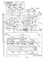
図1は、本発明の実施の形態のストレージシステム100の構成を示すブロック図である。
FIG. 1 is a block diagram showing a configuration of a
本実施の形態の計算機システムは、ストレージシステム100、管理計算機140、クライアント150A、クライアント150B及びこれらを相互に接続するLAN160を備える。
The computer system according to this embodiment includes a
管理計算機140は、ストレージシステム100を管理するための処理を実行する計算機である。例えば、管理計算機140は、ストレージシステム100内のファイルシステムの作成、ファイルシステムのマウント又はマイグレーションをサーバ110に指示する。さらに、管理計算機140は、ディスクサブシステム120及びスイッチ130に設定変更を指示する。
The
管理計算機140は、少なくとも、相互に接続された入力装置141、管理画面142、ディスク143、CPU144、ローカルメモリ145及びネットワークインターフェース(I/F)146を備える。管理計算機140は、CPU144、ローカルメモリ145及びネットワークI/F146を備える筐体(図示省略)と、その筐体に接続された入力装置141、管理画面142及びディスク143によって構成されてもよい。入力装置141は、例えば、システム管理者によって使用されるキーボード又はポインティングデバイスである。管理画面142は、例えば、システム管理者に情報を表示する画像表示装置である。管理画面142に表示される内容及びポインティングデバイスによる操作については、後述する(図16及び図17参照)。
The
ディスク143には、サーバ110等と通信するためのプログラム、及び、ディスクサブシステムを管理するためのプログラム等が格納される。これらのプログラムは、ローカルメモリ145上に読み出され、CPU144によって実行される。ネットワークI/F146は、サーバ110及びディスクサブシステム120との通信に使用される。
The
クライアント150A及び150Bは、ストレージシステム100のファイルにアクセスする計算機である。クライアント150A及び150Bは、ストレージシステム100にファイルを書き込み、又は、ストレージシステム100からファイルを読み出す。このとき、ストレージシステム100が管理するファイルシステムが使用される。クライアント150A及び150Bは、少なくとも、ファイルアクセスを実行するプログラムを格納するメモリ(図示省略)、及び、メモリに格納されたプログラムを実行するプロセッサ(図示省略)を備える。
The
図1では、二つのクライアント(150A及び150B)を示すが、任意の数のクライアントがLAN160に接続され、ストレージシステム100にアクセスすることができる。以下の説明において、二つのクライアントを特に区別する必要がない場合、これらを総称してクライアント150と記載する。
In FIG. 1, two clients (150A and 150B) are shown, but any number of clients can be connected to the
LAN160は、TCP/IP等のプロトコルで通信するネットワークである。
The
ストレージシステム100は、ネットワークアタッチドストレージ(Network Attached Storage、NAS)である。ストレージシステム100は、サーバ110A、サーバ110B、ディスクサブシステム120及びこれらを相互に接続するスイッチ130を備える。
The
スイッチ130は、例えばファイバーチャネル(FC)のスイッチ130である。ストレージシステム100は、複数のスイッチ130を備えてもよい。一つ以上のスイッチ130がストレージエリアネットワーク(SAN)を構成していてもよい。あるいは、スイッチ130は、LANのスイッチ又はストレージシステム専用のスイッチであってもよい。
The
サーバ110A及び110Bは、クライアント150から受信したアクセス要求に従ってディスクサブシステム120にアクセスする計算機である。
The servers 110 </ b> A and 110 </ b> B are computers that access the
以下の説明において、サーバ110A及び110Bを特に区別する必要がない場合、これらを総称してサーバ110と記載する。また、以下の説明において、サーバ110A及び110Bは、単にサーバA及びサーバBとも記載される。図1では、二つのサーバ110A及び110Bを示すが、ストレージシステム100は、さらに多くのサーバ110を備えてもよい。サーバ110は、NASヘッド又はNASノードとも呼ばれる。複数のサーバ110がクラスタ構成されていてもよい。
In the following description, when it is not necessary to particularly distinguish the
サーバ110Aは、相互に接続されたネットワークインターフェース111A、CPU112A、ローカルメモリ113A及びアダプタ116Aを備える。
The
ネットワークインターフェース111Aは、LAN160に接続され、管理計算機140及びクライアント150と通信するインターフェースである。
The network interface 111 </ b> A is an interface that is connected to the
CPU112Aは、サーバ110Aの動作を制御するプロセッサである。具体的には、CPU112Aは、ローカルメモリ113Aに格納されたプログラムを実行する。
The
ローカルメモリ113Aは、例えば、半導体メモリであり、CPU112Aが実行するプログラム及びCPU112Aによって参照されるデータを格納する。具体的には、ローカルメモリ113Aは、マウントテーブル(図示省略)、後述するサーバソフトウェア200及びマイグレーションポイント管理表600等を格納する。
The
アダプタ116Aは、スイッチ130に接続され、ディスクサブシステム120と通信するインターフェースである。
The adapter 116 </ b> A is an interface that is connected to the
サーバ110Bは、サーバ110Aと同様、ネットワークインターフェース111B、CPU112B、ローカルメモリ113B及びアダプタ116Bを備える。これらは、それぞれ、ネットワークインターフェース111A、CPU112A、ローカルメモリ113A及びアダプタ116Aと同様であるため、説明を省略する。さらに多くのサーバ110が設けられる場合、各サーバ110の構成は、サーバ110Aと同様であってよい。
As with the
ストレージシステム100が複数のサーバ110を備える場合、これらのサーバ110は、サーバ間通信路135によって相互に接続される。サーバ110は、サーバ間通信路135を経由して相互に通信することができる。
When the
具体的には、GNS管理表500が更新された場合に、その更新内容がサーバ間通信路135を経由して他のサーバ110に送信される。送信先のサーバ110は、受信した更新の内容をそのサーバ110内のGNS管理表500に反映する。
Specifically, when the GNS management table 500 is updated, the updated content is transmitted to the other server 110 via the
本実施の形態のストレージシステム100は、図1に示すように、スイッチ130及びLAN160のどちらからも独立したサーバ間通信路135を備える。しかし、サーバ110は、スイッチ130又はLAN160を経由して相互に通信してもよい。あるいは、サーバ110は、ディスクサブシステム120のディスクキャッシュ122を使用して相互に通信してもよい。サーバ110が上記のいずれの経路で通信しても、本発明を実施することができる。
As shown in FIG. 1, the
ディスクサブシステム120は、相互に接続されたディスクコントローラ121A、ディスクコントローラ121B、ディスクキャッシュ122及びディスクドライブ123を備える。ディスクコントローラ121Aは、スイッチ130に接続されるポート125A及び125Bを備える。ディスクコントローラ121Bは、スイッチ130に接続されるポート125C及び125Dを備える。以下の説明において、ディスクコントローラ121A及び121Bを特に区別する必要がない場合、これらを総称してディスクコントローラ121と記載する。また、ポート125Aから125Dを特に区別する必要がない場合、これらを総称してポート125と記載する。ディスクサブシステム120は、一つ又は三つ以上のディスクコントローラ121を備えてもよい。各ディスクコントローラ121は、一つ又は三つ以上のポート125を備えてもよい。
The
ディスクコントローラ121は、ポート125に接続されたスイッチ130を介してサーバ110と通信し、ディスクサブシステム120を制御する。具体的には、ディスクコントローラ121は、サーバ110からの要求に従ってディスクドライブ123にデータを書き込み、又は、ディスクドライブ123からデータを読み出す。
The disk controller 121 communicates with the server 110 via the
ディスクキャッシュ122は、例えば、半導体メモリであり、ディスクドライブ123に書き込まれるデータ又はディスクドライブ123から読み出されたデータを一時的に格納する。 The disk cache 122 is a semiconductor memory, for example, and temporarily stores data written to the disk drive 123 or data read from the disk drive 123.
ディスクドライブ123Aから123Dは、データを格納するハードディスクドライブである。ディスクサブシステムは、任意の数のディスクドライブ123A等を備える。以下の説明において、ディスクドライブ123Aから123Dを特に区別する必要がない場合、これらを総称してディスクドライブ123と記載する。これらのディスクドライブ123は、Redundant Arrays of Inexpensive Disks(RAID)を構成してもよい。
Disk drives 123A to 123D are hard disk drives for storing data. The disk subsystem includes an arbitrary number of
ディスクドライブ123の記憶領域は、任意の数の論理デバイス(LDEV)に分割して使用される。図1には、例として、4個のLDEV124Aから124Dを示す。以下の説明において、LDEV124Aから124Dを特に区別する必要がない場合、これらを総称してLDEV124と記載する。LDEV124は、ディスクコントローラ121によって論理的なディスクドライブとして扱われる領域である。ディスクドライブ123がRAIDを構成する場合、図1に示すように、一つのLDEV124が複数のディスクドライブ123の記憶領域によって構成されてもよい。各LDEV124の大きさは任意である。 The storage area of the disk drive 123 is divided into an arbitrary number of logical devices (LDEVs). FIG. 1 shows four LDEVs 124A to 124D as an example. In the following description, when it is not necessary to particularly distinguish the LDEVs 124A to 124D, these are collectively referred to as the LDEV 124. The LDEV 124 is an area handled as a logical disk drive by the disk controller 121. When the disk drive 123 constitutes a RAID, one LDEV 124 may be constituted by storage areas of a plurality of disk drives 123 as shown in FIG. The size of each LDEV 124 is arbitrary.
各LDEVには、LDEV識別子(ID)が付与される。図1の例において、LDEV124A〜LDEV124DのIDは、それぞれL0〜L3である。
Each LDEV is given an LDEV identifier (ID). In the example of FIG. 1, the IDs of LDEV 124A to
サーバ110は、各LDEV124内にファイルシステムを作成し、そのファイルシステムを管理する。各ファイルシステムには、ストレージシステム内で一意となるファイルシステム識別子(ID)が付与される。 The server 110 creates a file system in each LDEV 124 and manages the file system. Each file system is given a file system identifier (ID) that is unique within the storage system.
ストレージシステム100は、複数のディスクサブシステム120を備えてもよい。その場合、あるサーバ110は、スイッチ130を経由して、特定のディスクサブシステム120又は特定のディスクサブシステム120の集合のみにアクセスできてもよい。あるいは、各サーバ110が全てのディスクサブシステム120にアクセスすることができてもよい。
The
スイッチ130及びディスクサブシステム120は、それぞれ、LAN160に接続される管理用ポート131及び126を備える。管理計算機140は、LAN160を経由してこれらの管理用ポート131及び126と通信することによって、スイッチ130及びディスクサブシステム120の設定を参照し、又は、更新することができる。
The
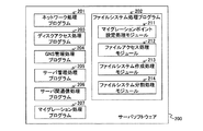
図2は、本発明の実施の形態のサーバソフトウェア200の説明図である。
FIG. 2 is an explanatory diagram of the
サーバソフトウェア200は、CPU112が実行するプログラムを含む。具体的には、サーバソフトウェア200は、ネットワーク処理プログラム201、ファイルシステム処理プログラム202、ディスクアクセス処理プログラム203、GNS管理処理プログラム204、サーバ管理処理プログラム205、サーバ間通信処理プログラム206及びマイグレーション処理プログラム207を含む。
ネットワーク処理プログラム201は、LAN160を介した管理計算機140及びクライアント150との通信を制御するプログラムである。
The
ファイルシステム処理プログラム202は、クライアント150からファイルシステム内のファイルへのアクセス要求、及び、管理計算機140からのファイルシステムに対する指示等を処理するプログラムである。ファイルシステム処理プログラム202のより詳細な説明は後述する。
The file
ディスクアクセスプログラム203は、ファイルシステム処理プログラム202が受けたファイルへのアクセス要求に基づき、実際にディスクサブシステム120へアクセスするプログラムである。
The
GNS管理処理プログラム204は、マイグレーション処理プログラム200がファイルシステムのマイグレーションを実行したときに、GNS管理表500を更新する。GNS管理表500の詳細は後述する(図5参照)。
The GNS
サーバ管理処理プログラム205は、管理計算機140と通信し、サーバ110の設定をするプログラムである。例えば、サーバ管理処理プログラム205は、管理計算機140からファイルシステムの新規作成の指示を受けると、その指示をファイルシステム処理プログラム202に伝え、ファイルシステムの新規作成を実行させる。管理計算機140からマイグレーションの指示を受けると、サーバ管理処理プログラム205は、その指示をマイグレーション処理プログラム207に伝え、マイグレーションを実行させる。
The server management processing program 205 is a program that communicates with the
サーバ間通信処理プログラム206は、サーバ間通信路135を経由したサーバ110間の通信を制御するプログラムである。例えば、サーバ間通信処理プログラム206は、GNS管理表500の内容を更新するため、他のサーバ110において実行されているGNS管理処理プログラム204に更新内容を送信する。
The inter-server
マイグレーション処理プログラム207は、マイグレーションを実行するプログラムである。マイグレーションとは、あるファイルシステムを、現在管理しているサーバ110から、別の指定されたサーバ110の管理下に移動させる処理のことである。
The
クライアント150がファイルシステム内のファイルにアクセスする場合、アクセス要求は、そのファイルシステムを管理するサーバ110によって処理される。従って、ファイルシステムをマイグレーションすることは、マイグレーション先のサーバへ負荷を分散することになる。マイグレーション処理によって、各サーバ110にかかる負荷が均衡し、ストレージシステム100全体の性能向上が可能となる。
When the client 150 accesses a file in the file system, the access request is processed by the server 110 that manages the file system. Therefore, migrating a file system distributes the load to the migration destination server. The load applied to each server 110 is balanced by the migration process, and the performance of the
ファイルシステム処理プログラム202は、マイグレーションポイント設定処理モジュール211、ファイルアクセス処理モジュール212、ファイルシステム作成処理モジュール213及びファイルシステム分割処理モジュール214を含む。
The file
マイグレーションポイント設定処理モジュール211は、管理用計算機140の指示に従って、サーバ110が持つマイグレーションポイント管理表600の更新処理を実行する。
The migration point setting processing module 211 executes update processing of the migration point management table 600 held by the server 110 in accordance with instructions from the
ファイルアクセス処理モジュール212は、クライアント150からの要求に基づき、ディレクトリ名又はファイル名の名前解決処理を実行し、ファイルの識別子であるファイルハンドルをクライアントに返す。また、例えば、クライアント150の要求するディレクトリ名やファイル名が、他のサーバ110によって管理されるディレクトリツリーに属する場合、そのディレクトリツリーを管理するサーバ110の位置情報(例えば、サーバ110のID)をクライアント150へ返す。ディレクトリツリーとは、ファイルシステム全体又はその一部に相当する一つ以上のディレクトリである。 Based on the request from the client 150, the file access processing module 212 executes a directory name or file name name resolution process and returns a file handle, which is a file identifier, to the client. Also, for example, when the directory name or file name requested by the client 150 belongs to a directory tree managed by another server 110, the location information (for example, the ID of the server 110) of the server 110 that manages the directory tree is displayed. Return to client 150. A directory tree is one or more directories corresponding to the entire file system or a part thereof.
ファイルシステム作成処理モジュール213は、管理計算機140の指示に従って、ファイルシステムを新規作成する。また、ファイルシステム作成処理モジュール213は、ファイルシステム分割処理モジュール214の指示に従って、ファイルシステムを新規作成する。
The file system
ファイルシステム分割処理モジュール214は、マイグレーション処理プログラム207の指示に従って、ファイルシステムの分割処理を実行する。ファイルシステムの分割処理の詳細は後述する(図9参照)。
The file system
図3は、本発明の実施の形態においてクライアント150に提供される共通名前空間の一例を示す説明図である。 FIG. 3 is an explanatory diagram illustrating an example of the common name space provided to the client 150 according to the embodiment of this invention.
共通名前空間は、一つ以上のサーバ110によって構成される。具体的には、共通名前空間は、各サーバ110が管理しているファイルシステムを統合することによって構成される一つの共通名前空間である。この共通名前空間をグローバルネームスペース(GNS)と呼ぶ。図3には、実施例を説明するために必要最小限のディレクトリ及びファイルを含むGNS300を示す。実際のGNSは、さらに多くのディレクトリ及びファイルを含んでもよい。 The common namespace is composed of one or more servers 110. Specifically, the common namespace is one common namespace configured by integrating file systems managed by the servers 110. This common namespace is called a global namespace (GNS). FIG. 3 shows a GNS 300 that includes the minimum number of directories and files necessary to describe the embodiment. An actual GNS may include more directories and files.
GNS300は、二つのサーバ、すなわち、サーバA及びサーバBによってGNSが構成される。次に、各サーバの名前空間について説明する。 In the GNS 300, a GNS is configured by two servers, that is, a server A and a server B. Next, the name space of each server will be described.
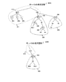
図4は、本発明の実施の形態の各サーバ110の名前空間の説明図である。 FIG. 4 is an explanatory diagram of the name space of each server 110 according to the embodiment of this invention.
図4は、例として、サーバAの名前空間400A及びサーバBの名前空間400Bを示す。最初に、名前空間400A及び400Bを構成する方法を説明し、次に、GNS300を構成する方法を説明する。
FIG. 4 shows the
サーバAは、三つのファイルシステム411、401及び402を管理する。それぞれのファイルシステムに属するディレクトリツリーを統合することによって、名前空間400Aが構成される。
Server A manages three
ファイルシステム411に相当するディレクトリツリーの最上位ディレクトリの下に、ディレクトリ「gns」414及び「mnt」がある。ディレクトリ「gns」414の下に、「a」403、「b」404及び「c」405の三つのディレクトリがある。一方、ディレクトリ「mnt」の下には、ディレクトリ「fs0」413及びディレクトリ「fs1」408がある。
Directories “gns” 414 and “mnt” are located under the top directory of the directory tree corresponding to the
ファイルシステム401に相当するディレクトリツリーの最上位ディレクトリの下に、ディレクトリ「aa」406及びディレクトリ「ab」がある。ディレクトリ「aa」の下には、ファイル「file1」がある。また、ディレクトリ「ab」の下には、ディレクトリ「ac」407がある。ディレクトリ「ac」407の下に、ディレクトリ「ad」及びディレクトリ「ae」がある。
A directory “aa” 406 and a directory “ab” are located under the top directory of the directory tree corresponding to the
ファイルシステム402に相当するディレクトリツリーの最上位ディレクトリの下に、ディレクトリ「ba」及びディレクトリ「bb」がある。ディレクトリ「ba」の下には、ディレクトリ「bc」がある。
A directory “ba” and a directory “bb” are present under the top directory of the directory tree corresponding to the
名前空間400Aのルートディレクトリ「/」は、ファイルシステム411の最上位ディレクトリである。サーバAは、ファイルシステム411に相当するディレクトリツリーにおけるパス「/mnt/fs0/」に、ファイルシステム401の最上位ディレクトリを繋ぎ、パス「/mnt/fs1/」に、ファイルシステム402の最上位ディレクトリを繋ぐことによって、一つの名前空間400Aを構成している。このように、一つのサーバ110によって管理されるファイルシステムの間で、あるファイルシステムのディレクトリツリーに、他のファイルシステムのディレクトリツリーを繋ぐことを、ローカルマウントと呼ぶ。また、ファイルシステム411のように、ルートディレクトリを持つファイルシステムを、ルートファイルシステムと呼ぶ。
The root directory “/” in the
サーバBは、二つのファイルシステム412及び409を管理する。それぞれのファイルシステムに属するディレクトリツリーを統合することによって、名前空間400Bが構成される。
Server B manages the two
ファイルシステム412に相当するディレクトリツリーの最上位ディレクトリの下に、ディレクトリ「mnt」がある。ディレクトリ「mnt」の下には、ディレクトリ「fs2」410がある。
There is a directory “mnt” under the top directory of the directory tree corresponding to the
ファイルシステム409に相当するディレクトリツリーの最上位ディレクトリの下に、ディレクトリ「ca」がある。ディレクトリ「ca」の下に、ファイル「file2」及びファイル「file3」がある。
A directory “ca” exists under the top directory of the directory tree corresponding to the
名前空間400Bのルートファイルシステムは、ファイルシステム412である。ルートファイルシステム内のパス「/mnt/fs2」に、ファイルシステム409に相当するディレクトリツリーをローカルマウントすることによって、名前空間400Bが構成される。
The root file system of the
次に、以上で説明したサーバAの名前空間400Aと、サーバBの名前空間400Bの一部を統合し、共通名前空間であるGNS300を構成する手法を示す。
Next, a method of integrating the part of the
名前空間400Aのパス「/gns/」をGNS300のルートディレクトリ「/」とする。GNS300のルートディレクトリを持つサーバAをGNSルートサーバと呼び、名前空間400Aのパス「/gns/」をGNSルートディレクトリと呼ぶ。GNSルートサーバとGNSルートディレクトリは、サーバソフトウェア200が記憶している。
The path “/ gns /” in the
GNSルートディレクトリ(名前空間400Aの「/gns/」)以下のディレクトリツリーが、GNS300に属するディレクトリツリーとなる。GNSルートディレクトリの下には、接続ポイントを作ることができる。接続ポイントに、ファイルシステムに相当するディレクトリを繋げることによって、一つのディレクトリツリーを構成することができる。GNS300の接続ポイントにファイルシステムを繋げることによって一つのディレクトリツリーを構成することを、「接続」と呼ぶ。
A directory tree below the GNS root directory (“/ gns /” in the
GNS300のGNSルートディレクトリの下には、三つの接続ポイント「/a/」403、「/b/」404及び「/c/」405がある。接続ポイント「/a/」403には、サーバAが管理するパス「/mnt/fs0/」にローカルマウントされているファイルシステム401が接続される。接続ポイント「/b/」404には、サーバAが管理するパス「/mnt/fs1/」にローカルマウントされているファイルシステム402が接続される。接続ポイント「/c/」405には、サーバBが管理するパス「/mnt/fs2/」にローカルマウントされているファイルシステム409が接続される。
Under the GNS root directory of the GNS 300, there are three connection points “/ a /” 403, “/ b /” 404, and “/ c /” 405. The connection point “/ a /” 403 is connected to the
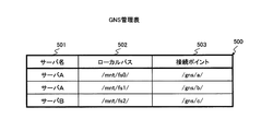
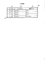
図5は、本発明の実施の形態のGNS管理表500の一例を示す説明図である。 FIG. 5 is an explanatory diagram illustrating an example of the GNS management table 500 according to the embodiment of this invention.
GNS管理表500は、各サーバ110のローカルメモリ113に格納され、各サーバ110によって個別に管理される。各サーバが格納するGNS管理表500には、同一の値が登録されている。GNS管理表500は、GNS300を構成する全てのファイルシステムを管理するためのテーブルであり、一つのエントリ(行)が、一つのディレクトリの接続ポイントを示す。 The GNS management table 500 is stored in the local memory 113 of each server 110 and is managed individually by each server 110. The same value is registered in the GNS management table 500 stored in each server. The GNS management table 500 is a table for managing all the file systems constituting the GNS 300, and one entry (row) indicates a connection point of one directory.
サーバ名501には、ファイルシステムを管理するサーバ名が登録される。ローカルパス502には、サーバ名501に登録されたサーバ110が管理する名前空間において、ファイルシステムがローカルマウントされているパスが登録される。接続ポイント503は、ローカルパス502にローカルマウントしているディレクトリが、GNS300上のどの接続ポイントに接続されているかを示す。
In the
GNS管理表500は、さらに、GNSルートサーバ及びGNSルートディレクトリを示す情報を含んでもよい。具体的には、図3及び図4の例に対応するGNS管理表500は、サーバAがGNSルートサーバであり、「/gns/」がGNSルートディレクトリであることを示す情報を含んでもよい。 The GNS management table 500 may further include information indicating a GNS root server and a GNS root directory. Specifically, the GNS management table 500 corresponding to the examples of FIGS. 3 and 4 may include information indicating that the server A is a GNS root server and “/ gns /” is a GNS root directory.
各サーバ110は、ルートファイルシステム内の名前解決と、そのルートファイルシステムに直接又は間接的にローカルマウントしているディレクトリ内の名前解決をすることができる。例えば、図3に示すGNS300の環境において、サーバ110AがGNS300上のファイル「/c/ca/file2」へのアクセス要求をクライアント150から受けたとする。サーバ110Aは、GNSルートサーバである。このため、サーバ110Aは、GNSルートディレクトリ「/gns/」をパス「/c/ca/file2」に付加し、GNS300のパスをローカルパス(サーバ110Aの名前空間におけるパス)に変換する。変換されたパスは、「/gns/c/ca/file2」となる。サーバAは、「/gns/」までの名前解決をすることはできる。しかし、サーバ110Aは、「/gns/c/」の名前解決をすることはできない。
Each server 110 can perform name resolution in the root file system and name resolution in a directory that is locally mounted directly or indirectly on the root file system. For example, in the environment of the GNS 300 shown in FIG. 3, it is assumed that the
このとき、サーバ110Aは、GNS管理表500を参照し、「/gns/c/」がサーバ110Bの管理下にあることを判断する。そして、アクセス要求を発行したクライアント150に位置情報を通知する。ここで通知される位置情報は、そのディレクトリを管理しているサーバの識別子を含み、必要があれば、そのサーバ内のローカルパスを含んでもよい。通知を受けたクライアント150は、サーバ110Bにアクセス要求を発行することによって、GNS300上のファイル「/c/ca/file2」へアクセスすることができる。
At this time, the
上記の例では、名前解決要求を受け取ったサーバAが、名前解決の対象となるファイルを管理しているサーバ110Bを識別する情報をクライアント150に通知する方法を示した。この方法とは異なり、名前解決要求を受け取ったサーバAがサーバBにクライアント150からの名前解決要求を転送し、サーバBが名前解決を実行してもよい。また、上記の例では、一つのファイルシステムが一つのサーバ110のみによって管理されていたが、複数のサーバ110が一つのファイルシステムを共有して管理してもよい。この場合、共有されたファイルシステムを更新する前に、更新を実行するサーバ110がファイルシステムのロックを取得することによって、更新が正しく実行されることを保証しなければならない。
In the above example, the server A that has received the name resolution request notifies the client 150 of information for identifying the
クライアント150にGNS300を提供する前に、管理計算機140は、予め、各サーバ110内にファイルシステムを分割する基点となるディレクトリパスを設定する。マイグレーションを実行する時に、このディレクトリパスを基点としてファイルシステムが分割され、分割されたファイルシステムがマイグレーションされる。その結果、よりきめ細かい粒度のマイグレーションが実現できる。このファイルシステムを分割する基点となるディレクトリパスをマイグレーションポイントと呼ぶ。各サーバ110は、それぞれ、マイグレーションポイント管理表600を使ってマイグレーションポイントを管理する。
Before providing the GNS 300 to the client 150, the
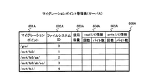
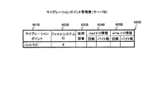
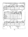
図6A及び図6Bは、本発明の実施の形態のマイグレーションポイント管理表600の一例を示す説明図である。 6A and 6B are explanatory diagrams illustrating an example of the migration point management table 600 according to the embodiment of this invention.
図6Aにおけるマイグレーションポイント管理表600Aは、サーバAのローカルメモリ113Aに格納されるマイグレーションポイント管理表600である。図6Bにおけるマイグレーションポイント管理表600Bは、サーバBのローカルメモリ113Bに格納されるマイグレーションポイント管理表600である。以下において、マイグレーションポイント管理表600A及び600Bのいずれにも共通する説明をする場合、図6A及び図6Bに表示された符号から「A」、「B」を省略して、「マイグレーションポイント601」のように記載する。
The migration point management table 600A in FIG. 6A is the migration point management table 600 stored in the
マイグレーションポイント601は、サーバ110内のローカルパスである。クライアント150がGNS300のファイルへアクセスするために使用されるGNSルートディレクトリと、GNS300を構成するために接続されているディレクトリとがマイグレーションポイント601として登録される。そして、各マイグレーションポイントにファイルシステムIDが与えられる。さらに、ファイルシステムを分割する基点としたいディレクトリもマイグレーションポイントとして登録され、予めファイルシステムIDが与えられる。 The migration point 601 is a local path in the server 110. A GNS root directory used for the client 150 to access the file of the GNS 300 and a directory connected to configure the GNS 300 are registered as the migration point 601. A file system ID is given to each migration point. Further, a directory that is desired to be a base point for dividing the file system is also registered as a migration point, and a file system ID is given in advance.
例えば、図6Aのマイグレーションポイント管理表600Aには、マイグレーションポイント601として、GNS300のルートディレクトリ「/gns/」、GNS300に接続している「/mnt/fs0/」及び「/mnt/fs1/」、並びに、ファイルシステム分割の基点となる「/mnt/fs0/aa/」及び「/mnt/fs0/ab/ac/」が登録されている。 For example, in the migration point management table 600A of FIG. 6A, as the migration point 601, the root directory “/ gns /” of the GNS 300, “/ mnt / fs0 /” and “/ mnt / fs1 /” connected to the GNS 300, In addition, “/ mnt / fs0 / aa /” and “/ mnt / fs0 / ab / ac /” which are the base points of the file system division are registered.
システム管理者は、予め、任意のディレクトリをマイグレーションポイント601に登録することができる。 The system administrator can register an arbitrary directory in the migration point 601 in advance.
ファイルシステムID602は、各ファイルシステム及び任意のディレクトリツリーに付与されたストレージシステム100内で一意の識別子である。管理計算機140は、マイグレーションポイント601をマイグレーションポイント管理表600に登録するとき、ストレージシステム100内で一意のファイルシステムIDを付与する。
The file system ID 602 is a unique identifier in the
クライアント150が、マイグレーションポイント601より下位のファイル(すなわち、マイグレーションポイント601以下のディレクトリツリーに属するファイル)の名前解決を実行した場合、ファイルシステム処理プログラム202は、ファイルハンドル(識別子)をクライアントに返す。そのファイルハンドルは、アクセス対象のファイルと最も近い上位のディレクトリ階層にあるマイグレーションポイント601に対応するファイルシステムID902と、アクセスするファイルに付与されたファイルIDとを含む。例えば、GNSのパス「/a/aa/file1」の名前解決を実行した場合、そのGNSのパスは、サーバAのローカルパス「/mnt/fs0/aa/file1」に対応する(図3から図5参照)。「/mnt/fs0/aa/file1」に最も近い上位のマイグレーションポイント601は、「/mnt/fs0/aa/」である。このため、クライアントに返されるファイルハンドルは、マイグレーションポイント「/mnt/fs0/aa/」のファイルシステムID「2」、及び、ファイルID「file1」を含む。
When the client 150 executes name resolution of a file lower than the migration point 601 (that is, a file belonging to a directory tree below the migration point 601), the file
一度マイグレーションポイント601に与えたファイルシステムID602は、マイグレーションが実行された後も変える必要はない。そのため、ストレージシステム100内の各ファイルを識別するファイルハンドルは、マイグレーションポイント601以下のディレクトリツリー単位でマイグレーションが実行されても常に一定となる。この仕組みを利用して、クライアント150から透過的に(言い換えると、各ファイル又はディレクトリがどのサーバに管理されているかをクライアント150に意識させることなく)、マイグレーションポイントを基点としてファイルシステムを分割することが可能となる。詳細は後述する(図8及び図9参照)。
The file system ID 602 once given to the migration point 601 does not need to be changed even after migration is executed. Therefore, the file handle for identifying each file in the
使用容量603〜writeI/O情報605には、各マイグレーションポイントの統計情報が登録される。使用容量603は、マイグレーションポイント以下のディレクトリツリーが使用しているディスクの容量を示す。readI/O情報604には、ディレクトリツリーの中のファイルが何回readアクセスされたか、及び、ディレクトリツリーの中のファイルが何バイト読み込まれたかが登録される。writeI/O情報605には、ディレクトリツリーの中のファイルが何回writeアクセスされたか、及び、ディレクトリツリーの中のファイルが何バイト書き込まれたかが登録される。 In the used capacity 603 to write I / O information 605, statistical information of each migration point is registered. The used capacity 603 indicates the capacity of the disk used by the directory tree below the migration point. The read I / O information 604 registers how many times a file in the directory tree is read-accessed and how many bytes the file in the directory tree is read. The write I / O information 605 registers how many times the file in the directory tree has been accessed for write and how many bytes of the file in the directory tree have been written.
例えば、readI/O情報604及びwriteI/O情報605は、毎秒の平均値でもよいし、所定の時間の累積値等であってもよい。さらに、使用容量603〜writeI/O情報605に登録される情報とは別に、例えば、毎分ごとにロギングした値が登録され、時間経過ごとの性能の変化が分かるようにしてもよい。 For example, the read I / O information 604 and the write I / O information 605 may be an average value every second, a cumulative value for a predetermined time, or the like. Further, separately from the information registered in the used capacity 603 to the write I / O information 605, for example, a value logged every minute may be registered so that a change in performance with time elapses can be known.
使用容量603〜writeI/O情報605に登録された情報は、どのサーバ110のマイグレーションポイントを、どこのサーバ110へマイグレーションするかを判断するための材料として使用することができる。詳細は後述する(図16及び図19参照)。 The information registered in the used capacity 603 to the write I / O information 605 can be used as a material for determining which server 110 migration point is migrated to which server 110. Details will be described later (see FIGS. 16 and 19).
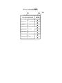
図7は、本発明の実施の形態のファイルシステムID管理表700の説明図である。 FIG. 7 is an explanatory diagram of the file system ID management table 700 according to the embodiment of this invention.
ファイルシステムID管理表700は、管理計算機140が参照することができるいずれかの場所に格納される。本実施の形態のファイルシステムID管理表700は、管理計算機140内のローカルメモリ145又はディスク143に格納される。
The file system ID management table 700 is stored in any location that can be referred to by the
管理計算機140は、各マイグレーションポイントにストレージシステム100内で一意のファイルシステムIDを付与するために、ファイルシステムID管理表700を参照する。ファイルシステムID管理表700は、ファイルシステムID701及び状態702からなる。
The
ファイルシステムID701には、各マイグレーションポイントに既に付与された、又はこれから付与されるファイルシステムIDが登録される。
In the
状態702には、各ファイルシステムID701が既にいずれかのマイグレーションポイントに付与されているか否かを示す値が登録される。状態702に「済」が登録されたファイルシステムID701は、既にストレージシステム100内でいずれかのマイグレーションポイントに付与されている。一方、状態702に「未」が登録されたファイルシステムID701は、ストレージシステム100内でまだいずれのマイグレーションポイントにも付与されていない。
In the
新たにマイグレーションポイントを設定するときに、管理計算機140は、そのマイグレーションポイントに、状態702の値が「未」であるファイルシステムID701を付与する。そして、そのファイルシステムID701に対応する状態702を「済」に更新する。その結果、新たに設定されるマイグレーションポイントには、常に、ストレージシステム内でまだどのマイグレーションポイントにも付与されていないファイルシステムID701が付与される。
When a new migration point is set, the
次に、本実施の形態において実行されるマイグレーション処理について説明する。 Next, the migration process executed in this embodiment will be described.
サーバ110にマイグレーションの実行契機を与えるいくつかの方法が考えられる。例えば、システム管理者が管理計算機140を介してサーバソフトウェア200にマイグレーションの指示を与えてもよい。あるいは、サーバソフトウェア200が自動的に判断してマイグレーション処理を開始してもよい。あるいは、別の方法によって実行契機が与えられてもよい。いずれの方法であっても本発明を実施することができる。
There are several methods for giving the server 110 an opportunity to execute migration. For example, the system administrator may give a migration instruction to the
次に、本発明の実施例におけるマイグレーションの実行処理の手順を、図8及び図9を参照して説明する。なお、サーバソフトウェア200に含まれるプログラム及びモジュールは、ローカルメモリ113に格納され、CPU112によって実行される。このため、以下の説明において各プログラム又はモジュールが実行する処理は、実際には、CPU112によって実行される。
Next, the procedure of the migration execution process in the embodiment of the present invention will be described with reference to FIGS. Note that the programs and modules included in the
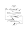
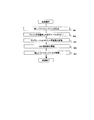
図8は、本発明の実施の形態のマイグレーション処理プログラム207が実行する処理のフローチャートである。
FIG. 8 is a flowchart of processing executed by the
サーバ110が、マイグレーションの対象となるマイグレーションポイントを指定したマイグレーションの指示を管理計算機140から受信したとき、マイグレーション処理プログラム207は、図8に示す処理を開始する。あるいは、マイグレーション処理プログラム207自身が、例えば、マイグレーションポイント管理表600に登録された統計情報等を参照して、マイグレーションを実行するか否かを判定してもよい。マイグレーション処理プログラム207は、マイグレーションを実行すると判定した場合に、図8の処理を開始する。
When the server 110 receives a migration instruction specifying a migration point to be migrated from the
最初に、マイグレーション処理プログラム207は、ファイルシステムを分割する必要があるか否かを判断する(801)。
First, the
マイグレーション処理プログラム207が受信したマイグレーションポイント以下のディレクトリツリーがファイルシステム全体である場合(言い換えると、受信したマイグレーションポイントがファイルシステムの最上位ディレクトリである場合)、ファイルシステム全体がマイグレーションされる。この場合、ファイルシステムを分割する必要がないため、判定の結果は「いいえ」となり、ステップ804の処理に進む。
When the directory tree below the migration point received by the
一方、マイグレーション処理プログラム207が受信したマイグレーションポイント以下のディレクトリツリーがファイルシステムの一部分である場合、ファイルシステムを分割する必要がある。このため、判定の結果は「はい」となり、ステップ802の処理に進む。
On the other hand, when the directory tree below the migration point received by the
マイグレーション処理プログラム207は、ステップ802において、ファイルシステム分割処理モジュール214を呼び出す。ファイルシステム分割処理モジュール214が実行する処理の詳細については後述する(図9参照)。
In
次に、マイグレーション処理プログラム207は、ファイルシステム分割処理802による分割の結果新しく作成されたファイルシステムをマイグレーションする必要があるか否かを判定する(803)。
Next, the
後述するように、ステップ802において局所分割が実行された場合、分割されたファイルシステムをマイグレーションする必要がある。一方、遠隔分割が実行された場合、分割されたファイルシステムをマイグレーションする必要がない。
As will be described later, when local division is executed in
ステップ803において、マイグレーションを実行する必要があると判定された場合、マイグレーション処理プログラム207は、分割されたファイルシステムのマイグレーションを実行して(804)、処理を終了する。
If it is determined in
具体的には、マイグレーション処理プログラム207は、ステップ804において、マイグレーションの対象となる分割されたファイルシステムに含まれる全てのファイルを、マイグレーション先のサーバ110に送信する。マイグレーション先のサーバのマイグレーション処理プログラム207は、受信したファイルを、いずれかのLDEV124に格納する。
Specifically, in
一方、ステップ803において、マイグレーションを実行する必要がないと判定された場合、マイグレーション処理プログラム207は、マイグレーションを実行せずに、処理を終了する。
On the other hand, if it is determined in
図9は、本発明の実施の形態のファイルシステム処理プログラム202内のファイルシステム分割処理モジュール214が実行する処理のフローチャートである。
FIG. 9 is a flowchart of processing executed by the file system
図9の処理は、図8のステップ802においてマイグレーション処理プログラム207によって呼び出されたときに、ファイルシステム分割処理モジュール214によって実行される。
The processing in FIG. 9 is executed by the file system
最初に、ファイルシステム分割処理モジュール214は、新しいファイルシステムを作成する(901)。ここで、ファイルシステム分割処理モジュール214は、自サーバ(すなわち、分割の対象のファイルシステムを管理しているサーバ110)が管理する新たなファイルシステムを作成してもよいし、自サーバ以外のサーバ110が管理する新たなファイルシステムを作成してもよい。前者のようにして実行される分割を、以下の説明において「局所分割」と記載する。後者のようにして実行される分割を、以下の説明において「遠隔分割」と記載する。局所分割の具体例は、後で図10から図12を参照して説明する。遠隔分割の具体例は、後で図13から図15を参照して説明する。
First, the file system
次に、ファイルシステム分割処理モジュール214は、ステップ901において作成されたファイルシステムに、分割の対象となるマイグレーションポイント以下のディレクトリに属するファイルを、ファイルIDを維持したままコピーする(902)。マイグレーションによってファイルハンドルが変更されることを防ぐために、ファイルIDを維持する必要があるためである。このため、サーバ110のオペレーティングシステム(OS)は、ファイルIDを指定したファイルのコピーをする機能を備える必要がある。
Next, the file system
次に、ファイルシステム分割処理モジュール214は、マイグレーションポイント管理表600を更新する(903)。この更新については後述する。
Next, the file system
次に、ファイルシステム分割処理モジュール214は、GNS管理表500を更新する(904)。具体的には、ファイルシステム分割処理モジュール214は、GNS管理処理プログラム204を呼び出し、GNS管理表500を更新させる。この更新については後述する(図12及び図15参照)。
Next, the file system
次に、ファイルシステム分割処理モジュール214は、作成された新しいファイルシステムをGNSに接続する(905)。具体的には、マウントテーブル(図示省略)が更新される。マウントテーブルの更新は、従来と同様の方法によって実行されてもよい。このため、詳細な説明は省略する。
Next, the file system
以上で、ファイルシステム分割処理モジュール214は、処理を終了する。
Thus, the file system
次に、ステップ901において自サーバが管理する新たなファイルシステムが作成される場合の図9の処理の具体例を、図10から図12を参照して説明する。
Next, a specific example of the processing in FIG. 9 when a new file system managed by the server is created in
具体的には、サーバAのマイグレーションポイント「/mnt/fs0/ab/ac/」407以下のディレクトリツリーを分割し、サーバAが管理する新しいファイルシステムを作成する場合を例として説明する。 Specifically, a case will be described as an example in which a directory tree below the migration point “/ mnt / fs0 / ab / ac /” 407 of the server A is divided to create a new file system managed by the server A.
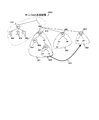
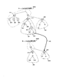
図10は、本発明の実施の形態において局所分割が実行されているときの名前空間の一例の説明図である。 FIG. 10 is an explanatory diagram showing an example of a name space when local division is executed in the embodiment of the present invention.
図10のうち、図4において既に説明した部分については、説明を省略する。 10 that are already described in FIG. 4 will not be described.
ファイルシステム分割処理モジュール214は、サーバAが利用可能な未使用のLDEV124に新しいファイルシステム1002を作成する(901)。さらに、ファイルシステム分割処理モジュール214は、作成された新しいファイルシステム1002をサーバAのローカルパス「/mnt/fs3/」にローカルマウントする。
The file system
次に、ファイルシステム分割処理モジュール214は、マイグレーションポイント407以下のディレクトリツリー1001に属するファイル「ad」及び「ae」を、ファイルIDを維持したまま、ファイルシステム1002以下のディレクトリツリーにコピーする(902)。ディレクトリツリー1001は、ファイルシステム401の一部に相当する。
Next, the file system
次に、ファイルシステム分割処理モジュール214は、マイグレーションポイント管理表600Aのマイグレーションポイント601A「/mnt/fs0/ab/ac/」を「/mnt/fs3/」に書き換える(903)。
Next, the file system
次に、GNS管理処理プログラム204がGNS管理表500を更新する(904)。具体的には、GNS管理処理プログラム204は、GNS管理表500に新たな行1201を追加する。更新されたGNS管理表1200は、図12に示す通りである。追加される行1201のサーバ名501には「サーバA」、ローカルパス502には「/mnt/fs3/」、接続ポイント503には「/gns/a/ab/ac/」が登録される。
Next, the GNS
次に、ファイルシステム分割処理モジュール214は、書き換えられたGNS管理表1200に従って、サーバAのローカルパス「/mnt/fs3/」1003を接続ポイント「/gns/a/ab/ac/」1101(図11参照)に接続する(905)。
Next, the file system
以上で、ファイルシステムの局所分割が終了する。 This completes the local division of the file system.
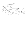
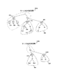
図11は、本発明の実施の形態において局所分割が実行された後の名前空間の一例の説明図である。 FIG. 11 is an explanatory diagram of an example of the name space after the local division is executed in the embodiment of the present invention.
図11は、図10に示す局所分割の実行が終了した後の名前空間である。図11のうち、図10において既に説明した部分については、説明を省略する。 FIG. 11 shows the name space after the execution of the local division shown in FIG. 11 that are already described in FIG. 10 will not be described.
サーバAのローカルパス「/mnt/fs0/ab/ac/」の下のファイル「ad」及び「ae」が削除され、「/gns/a/ab/ac/」1101が新たな接続ポイントとして設定されている。 Files “ad” and “ae” under local path “/ mnt / fs0 / ab / ac /” of server A are deleted, and “/ gns / a / ab / ac /” 1101 is set as a new connection point Has been.
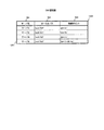
図12は、本発明の実施の形態において局所分割が実行された後のGNS管理表1200の一例の説明図である。 FIG. 12 is an explanatory diagram of an example of the GNS management table 1200 after the local division is executed in the embodiment of this invention.
GNS管理表1200には、図10において説明したように、新たな行1201が追加されている。
As described with reference to FIG. 10, a
局所分割が終了した後、新たに作成されたファイルシステムを他のサーバ110へマイグレーションする必要がある。図11の例では、ファイルシステム1002を、例えばサーバBにマイグレーションする必要がある。このため、図8のステップ803において「はい」と判定され、ステップ804のマイグレーションが実行される。
After the local division is completed, it is necessary to migrate the newly created file system to another server 110. In the example of FIG. 11, the
例えば、後述する図13に示すように、ファイルシステム1002がサーバBにマイグレーションされる場合、マイグレーションが実行された後のサーバA及びサーバBのローカル名前空間は、後述する図14に示す通りとなる。このとき、マイグレーションポイント管理表600Aの「/mnt/fs3/」に対応する行は、マイグレーションポイント管理表600Bに移動する。そして、マイグレーションが実行された後のGNS管理表500は、後述する図15に示す通りとなる。
For example, as illustrated in FIG. 13 described later, when the
マイグレーションが実行される前、マイグレーションポイント管理表600Aの「/mnt/fs3/」に対応するファイルシステムID602Aの値は「3」であった。このため、「/mnt/fs3/」に対応する行がマイグレーションポイント管理表600Bに移動するときに、パス名「/mnt/fs3/」だけでなく、移動する行のファイルシステムID602Aの値「3」が、移動先のサーバBに送信される。この送信は、LAN160、サーバ間通信路135又はその他のネットワークを介して実行されてもよい。移動先のサーバBは、移動元のサーバAから送信されたパス名「/mnt/fs3/」及びファイルシステムID「3」を、それぞれ、マイグレーションポイント601B及びファイルシステムID602Bに登録する。その結果、マイグレーションされたファイルは、マイグレーション実行前と同じファイルハンドルによって識別される。
Before the migration was executed, the value of the
ここで、ファイルIDを維持したままコピーする方法(図9のステップ902参照)について補足説明する。ファイルIDとは、各ファイルごとに付与される識別子であり、ファイルシステム内で一意となる。ファイルIDを維持したままコピーするためには、コピー先のファイルシステムに同じファイルIDを持つファイルがないことを保証しなければならない。しかし、ステップ901で作成されたばかりのファイルシステムには、登録されているファイルが無いため、ファイルIDが重なることがないことが保証できる。そのため、ファイルIDを維持したままファイルをコピーすることが可能となる。言い換えると、一つのファイルがマイグレーションされたとき、マイグレーション実行後のマイグレーション先のサーバ110は、マイグレーション元のサーバ110がそのファイルを識別するために使用したファイルIDと同一のファイルIDを使用して、マイグレーションの対象のファイルを識別する。
Here, a supplementary description will be given of a method of copying while maintaining the file ID (see
クライアント150は、GNSのファイルにアクセスする場合、システム内で一意なファイルシステムIDとファイルシステム内で一意なファイルIDとを組み合わせて作成されるファイルハンドルを使用し、システム内のファイルを一意に識別する。サーバ110は、ファイルハンドルを指定したアクセス要求を受信すると、指定されたファイルハンドルによって識別されるファイルに対するアクセスを実行する。 When the client 150 accesses a GNS file, it uses a file handle created by combining a unique file system ID in the system and a unique file ID in the file system, and uniquely identifies the file in the system. To do. When the server 110 receives the access request specifying the file handle, the server 110 executes access to the file identified by the specified file handle.
本発明によれば、ファイルシステムの分割が実行される前後で、ファイルシステムIDもファイルIDも変わらない。また、ファイルシステム分割後にファイルシステムをマイグレーションしても、ファイルシステムIDとファイルIDのいずれも変わることはない。そのため、クライアント150は、ファイルシステム分割前に取得したファイルハンドルを使用して、ファイルシステム分割後も、ファイルシステムのマイグレーション後も、一意のファイルにアクセスすることができる。 According to the present invention, the file system ID and the file ID do not change before and after the file system division is executed. Further, even if the file system is migrated after the file system is divided, neither the file system ID nor the file ID is changed. Therefore, the client 150 can access a unique file by using the file handle acquired before the file system is divided, both after the file system is divided and after the file system is migrated.
分割によって作成される新しいファイルシステムを、あらかじめマイグレーション先のサーバ110に作成してもよい。そのようにして実行される分割が、遠隔分割である。例えば、分割元のファイルシステム401のマイグレーションポイント407以下のディレクトリツリーを分割し、新しいファイルシステムをサーバBが管理するファイルシステムとして作成する場合に実行される図9の処理を、図13〜図15を参照して説明する。
A new file system created by the division may be created in the migration destination server 110 in advance. The division performed in this way is remote division. For example, the processing of FIG. 9 executed when the directory tree below the
図13は、本発明の実施の形態において遠隔分割が実行されているときの名前空間の一例の説明図である。 FIG. 13 is an explanatory diagram showing an example of a name space when remote division is executed in the embodiment of the present invention.
図13のうち、図4又は図10において既に説明した部分については、説明を省略する。 13 that are already described in FIG. 4 or FIG.
ファイルシステム分割処理モジュール214は、サーバBが利用可能な未使用のLDEV124に新しいファイルシステム1302を作成する(901)。さらに、ファイルシステム分割処理モジュール214は、作成された新しいファイルシステム1302をサーバBのローカルパス「/mnt/fs3/」にローカルマウントする。
The file system
次に、ファイルシステム分割処理モジュール214は、マイグレーションポイント「/mnt/fs0/ab/ac/」407以下のディレクトリツリー1301以下のファイル「ad」及び「ae」を、ファイルIDを維持したまま、ファイルシステム1302にコピーする(902)。このコピーは、LAN160を介して実行されてもよいし、他のネットワークを介して実行されてもよい。
Next, the file system
次に、サーバAのファイルシステム分割処理モジュール214は、マイグレーションポイント管理表600Bに「/mnt/fs3/」をマイグレーションポイントとして追加する指示をサーバBに送信する(903)。
Next, the file system
この指示には、マイグレーションポイント管理表600Bに新たに追加されるマイグレーションポイントID「/mnt/fs3/」と、マイグレーションポイント管理表600AにおいてそのIDと対応して登録されていたファイルシステムID602Aの値「3」が含まれる。その結果、マイグレーションポイント管理表600Bに新たに追加される行のマイグレーションポイントID601B及びファイルシステムID602Bは、それぞれ、「/mnt/fs3/」及び「3」となる。その結果、マイグレーションされたファイルは、マイグレーション実行前と同じファイルハンドルによって識別される。
In this instruction, the migration point ID “/ mnt / fs3 /” newly added to the migration point management table 600B and the value “of the
次に、ファイルシステム分割処理モジュール214は、GNS管理処理プログラム204に、GNS管理表500を更新する指示を送信する(904)。GNS管理処理プログラム204は、GNS管理表500に新たな行1501を追加する。更新されたGNS管理表1500は、図15に示す通りである。追加される行1501のサーバ名501には「サーバB」、ローカルパス502には「/mnt/fs3/」、接続ポイント503には「/gns/a/ab/ac/」が登録される。
Next, the file system
次に、ファイルシステム分割処理モジュール214は、書き換えられたGNS管理表1500に従って、サーバBのローカルパス「/mnt/fs3/」1303を接続ポイント「/gns/a/ab/ac/」1401(図14参照)に接続する(905)。
Next, the file system
以上で、ファイルシステムの遠隔分割が完了する。 This completes the remote division of the file system.
図14は、本発明の実施の形態において遠隔分割が実行された後の名前空間の一例の説明図である。 FIG. 14 is an explanatory diagram showing an example of the name space after the remote division is executed in the embodiment of the present invention.
図14は、図13に示す遠隔分割の実行が終了した後の名前空間である。図14のうち、図13において既に説明した部分については、説明を省略する。 FIG. 14 shows the name space after the remote division shown in FIG. 13 is finished. 14 that are already described in FIG. 13 will not be described.
サーバAのローカルパス「/mnt/fs0/ab/ac/」の下のファイル「ad」及び「ae」が削除され、「/gns/a/ab/ac/」1401が新たな接続ポイントとして設定されている。 Files “ad” and “ae” under local path “/ mnt / fs0 / ab / ac /” of server A are deleted, and “/ gns / a / ab / ac /” 1401 is set as a new connection point Has been.
図15は、本発明の実施の形態において遠隔分割が実行された後のGNS管理表1500の一例の説明図である。 FIG. 15 is an explanatory diagram of an example of the GNS management table 1500 after the remote division is executed in the embodiment of this invention.
GNS管理表1500には、図13において説明したように、新たな行1501が追加されている。
As described with reference to FIG. 13, a
以上の遠隔分割によれば、分割の終了と同時に他のサーバ110へのファイルシステムのマイグレーションも終了している。このため、図8のステップ803において「いいえ」と判定され、ステップ804のマイグレーションは実行されない。
According to the above remote division, the migration of the file system to another server 110 is completed simultaneously with the completion of the division. For this reason, “No” is determined in
ファイルシステムの作成901、ファイルのコピー902、データの二重書き、及び、GNS管理処理プログラム204との通信は、LAN160を介して実行されてもよいし、サーバ間通信路135を介して実行されてもよい。
The
図10〜図13の例のように、元のファイルシステムを管理するサーバ110に新しいファイルシステムを作成してからマイグレーションを実行する方法を局所分割マイグレーションと呼ぶ。図13〜図15の例のように、予めマイグレーション先のサーバ110に新しいファイルシステムを作成する方法を遠隔分割マイグレーションと呼ぶ。 A method of executing migration after creating a new file system in the server 110 that manages the original file system as in the example of FIGS. 10 to 13 is called local division migration. A method of creating a new file system in advance in the migration destination server 110 as in the examples of FIGS. 13 to 15 is called remote division migration.
局所分割マイグレーション及び遠隔分割マイグレーションには、それぞれ相反する長所、短所がある。局所分割マイグレーションの長所は、スイッチ130の設定を変更して、サーバ110とディスクコントローラ125間のパスを切り換えるだけでファイルシステムのマイグレーションができる場合、サーバ110間のファイルコピー等によるネットワーク帯域の消費を節約できることである。例えば、サーバAからサーバBへのマイグレーションが実行されるとき、サーバAとサーバBが同じディスクサブシステム120を共有していれば、スイッチ130の設定を変えることで、マイグレーションの対象のファイルシステムが入っているLDEV124をサーバAからサーバBの管理下に移すことができる。
Local split migration and remote split migration have conflicting advantages and disadvantages, respectively. The advantage of local split migration is that if the file system can be migrated simply by changing the setting of the
局所分割マイグレーションの短所は、マイグレーション元のディスクサブシステム120の空き容量が足りない場合、及び、LDEV124を使い切ったために新たなファイルシステムを作れない場合に実行できないことである。
Disadvantages of local split migration are that it cannot be executed when there is not enough free space in the migration
遠隔分割マイグレーションの長所は、マイグレーション元のディスクサブシステム120の空き容量が足りない場合、又は、LDEV124が足りない場合であっても、マイグレーション先のディスクサブシステム120の空き容量又はLDEV数に余裕があれば、マイグレーションが可能なことである。
The advantage of remote split migration is that there is room in the free capacity or number of LDEVs in the migration
遠隔分割マイグレーションの短所は、スイッチ130の設定を変更して、サーバ110とディスクコントローラ125間のパスを切り換えるだけでファイルシステムのマイグレーションが済む場合であっても、ネットワーク帯域を消費してしまうことである。
The disadvantage of remote split migration is that even if the file system migration is completed simply by changing the setting of the
本発明では、以上の局所分割マイグレーションと遠隔分割マイグレーションを組み合わせて使用することによって、より効率の良いファイルシステムのマイグレーションを実行することができる。 In the present invention, by using a combination of the above-mentioned local division migration and remote division migration, a more efficient migration of the file system can be executed.
次に、マイグレーションの実行契機を与える具体例として、管理者が管理計算機140からサーバ110へマイグレーションの実行を指示するためのグラフィカルユーザインターフェース(GUI)を図16及び図17に例示する。
Next, as a specific example for giving an execution timing of migration, FIGS. 16 and 17 illustrate a graphical user interface (GUI) for an administrator to instruct execution of migration from the
図16は、本発明の実施の形態の管理計算機140に表示されるマイグレーションポイント選択ウィンドウの説明図である。
FIG. 16 is an explanatory diagram of a migration point selection window displayed on the
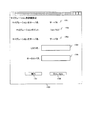
マイグレーションポイント選択ウィンドウ1600は、管理計算機140の管理画面142に表示される。マイグレーションポイント選択ウィンドウ1600には、マイグレーション元サーバリスト1650、マイグレーションポイントリスト1660及びマイグレーション先サーバリスト1670が表示される。
The migration
マイグレーション元サーバリスト1650は、システム管理者がどのサーバ110のディレクトリツリーをマイグレーションするかを決定するために表示される。マイグレーション元サーバリスト1650は、サーバ名1601、空き容量1602、空きLDEV数1603、CPU負荷1604及びネットワーク帯域1605を含む。
The migration
サーバ名1601には、マイグレーション元となるサーバ110の候補が表示される。空き容量1602には、サーバ名1601が示すサーバ110が利用できるディスクサブシステム120の空き容量が表示される。空きLDEV数1603には、サーバ名1601が示すサーバ110が利用できるディスクサブシステム120に設定されたLDEVの数が表示される。CPU負荷1604には、サーバ名1601が示すサーバ110が現在使用しているCPU112の負荷の値(例えば、%)が表示される。ネットワーク帯域1605には、サーバ名1601が示すサーバ110が現在使用しているネットワーク帯域の量(例えば、bytes毎秒)が表示される。システム管理者は、エントリの選択ボタン1606を操作することによって、サーバ名1601を選択することができる。選択されたサーバ名1601が示すサーバ110が、マイグレーション元のサーバ110となる。
In the
なお、システム管理者による選択ボタン1606の操作は、入力装置141によって実行される。例えば、入力装置141がマウスを含む場合、システム管理者は、選択ボタン1606上でマウスクリックをすることによって操作してもよい。実行ボタン1631等についても同様である。
Note that the operation of the
システム管理者は、マイグレーション元として、例えば、空き容量1602が少ないサーバ110を選択してもよいし、空きLDEV数1603が少ないサーバ110を選択してもよいし、CPU負荷1604が高いサーバ110を選択してもよいし、ネットワーク帯域1605の使用量の高いサーバ110を選択してもよい。あるいは、列1602〜1605までの各種情報を組み合わせてマイグレーション元のサーバ110を選択してもよい。
As a migration source, for example, the system administrator may select a server 110 with a small free capacity 1602, a server 110 with a small number of free LDEVs 1603, or a server 110 with a
マイグレーション元サーバのマイグレーションポイントリスト1660には、選択ボタン1606によって選択されたサーバ110のマイグレーションポイント管理表600が表示される。マイグレーションポイントリスト1660に含まれるマイグレーションポイント1611、使用容量1612、readI/O情報1613及びwriteI/O情報1614には、それぞれ、マイグレーションポイント管理表600に登録されているマイグレーションポイント601、使用容量603、readI/O情報604及びwriteI/O情報605の値が表示される。
In the
システム管理者は、選択ボタン1615を操作することによって、マイグレーションポイントリストに表示されたマイグレーションポイントの中から、マイグレーションしたいディレクトリツリーを選択する。具体的には、システム管理者は、マイグレーションしたいディレクトリツリーの最上位ディレクトリを、マイグレーションポイント1611から選択する。
The system administrator operates the
マイグレーション先サーバリスト1670には、サーバ名1621、空き容量1622、空きLDEV数1623、CPU負荷1624及びネットワーク帯域1625が表示される。システム管理者は、選択ボタン1615を操作して選択したマイグレーションポイント以下のディレクトリツリーをマイグレーションする先のサーバ110を、マイグレーション先サーバリスト1670から選択する。この選択は、システム管理者が選択ボタン1626を操作することによって実行される。
In the migration
サーバ名1621には、マイグレーション先の候補となるサーバ110の名前が表示される。空き容量1622は、サーバ名1621が示すサーバ110が利用できるディスクサブシステム120の空き容量が表示される。空きLDEV数1623には、サーバ名1621が示すサーバ110が利用できるディスクサブシステムの空きLDEVの数が表示される。CPU負荷1624には、サーバ名1621が示すサーバ110が現在使用しているCPU112の負荷の値(例えば、%)が表示される。ネットワーク帯域1625には、サーバ名1621が示すサーバ110が現在使用しているネットワーク帯域の量(例えば、bytes毎秒)が表示される。
The
システム管理者がマイグレーション実行ボタン1631を操作すると、マイグレーション先の詳細入力ウィンドウ1700が表示される(図17参照)。キャンセルボタン1632は、マイグレーションポイント選択ウィンドウ1600を閉じ、マイグレーション処理をキャンセルするために使用される。
When the system administrator operates the
図17は、本発明の実施の形態のマイグレーション先詳細設定ウィンドウ1700の説明図である。
FIG. 17 is an explanatory diagram of the migration destination detailed setting
マイグレーション先詳細設定ウィンドウ1700は、マイグレーション元サーバ名表示欄1701、マイグレーションポイント表示欄1702、マイグレーション先サーバ名表示欄1703、LDEV名入力欄1704、ローカルパス入力欄1705、実行ボタン1731及びキャンセルボタン1732を含む。
The migration destination detailed setting
マイグレーション元サーバ名表示欄1701には、図16の選択ボタン1606によって選択されたマイグレーション元のサーバ110のサーバ名1601が表示される。図17の例では、「サーバA」が表示されている。マイグレーションポイント表示欄1702には、選択ボタン1615によって選択されたマイグレーションポイント1611が表示される。図17の例では、「/mnt/fs3/」が表示されている。マイグレーション先サーバ名表示欄1703には、選択ボタン1626によって選択されたマイグレーション先のサーバ110のサーバ名1621が表示される。図17の例では、「サーバB」が表示されている。
In the migration source server
システム管理者は、マイグレーション先のサーバ110が利用することができるLDEV124の中から、マイグレーション先として使用するものを選択し、そのLDEV124のLDEV名をLDEV名入力欄1704に入力する。
The system administrator selects one to be used as the migration destination from among the LDEVs 124 that can be used by the migration destination server 110, and inputs the LDEV name of the LDEV 124 into the LDEV
さらに、システム管理者は、マイグレーション先のLDEV124に作成されるファイルシステムをローカルマウントするマイグレーション先のサーバ110のローカルパスを指定し、そのローカルパスをローカルパス入力欄1705に入力する。その結果、マイグレーション先サーバ名表示欄1703に表示されたサーバ110の、ローカルパス入力欄1705に入力されたローカルパスに、マイグレーション先のファイルシステムが作成される。ローカルパス入力欄1705に入力される値は、GNS管理表500のローカルパス502に対応している。
Further, the system administrator designates the local path of the migration destination server 110 that locally mounts the file system created in the migration destination LDEV 124, and inputs the local path in the local
システム管理者が実行ボタン1731を操作すると、管理計算機140は、サーバソフトウェア200へマイグレーションの開始を指示する。システム管理者がキャンセルボタン1732を選択すると、マイグレーション先詳細設定ウィンドウ1700が閉じる。
When the system administrator operates the execute
局所分割マイグレーションと遠隔分割マイグレーションは、自動的に使い分けられてもよい。例えば、サーバAからサーバBへのマイグレーションが実行されるとき、サーバAとサーバBが同じディスクサブシステム120を共有している場合、LDEV名入力欄1704に入力されたLDEV124へのマイグレーションは、パスを切り替えるだけで実行することができる。このとき、局所分割に使用するLDEV124のファイルシステムを一時的にサーバAにローカルマウントするためのディレクトリは、管理計算機140によって自動生成されてもよい。
Local division migration and remote division migration may be automatically used separately. For example, when migration from server A to server B is executed, if server A and server B share the
サーバAとサーバBが同じディスクサブシステム120を共有していない場合、パス切り替えによってマイグレーションを実行することができない。このため、自動的に、遠隔分割マイグレーションが選択され、実行される。その場合は、LDEV名入力欄1704に入力されたLDEV124がサーバBに確保され、そのLDEV124にファイルシステムが作成される。そして、作成されたファイルシステムに、マイグレーションポイント表示欄1702に表示されたディレクトリ以下のファイルを、ファイルIDを維持したままコピーすることによって、マイグレーションが実行される。
If server A and server B do not share the
図16及び図17では、システム管理者がGUIウィンドウを使用してマイグレーション開始の契機を与える方法について説明した。しかし、GUIウィンドウは、マイグレーションの契機を与える方法のうちの一つであり、他の方法によってマイグレーションの契機が与えられてもよい。例えば、コマンドラインインターフェース(CLI)によってマイグレーションの契機が与えられてもよい。あるいは、マイグレーション元サーバの統計情報、マイグレーションポイント管理表の統計情報及びマイグレーション先サーバの統計情報に基づいて、どのサーバ110のどのマイグレーションポイントをどのサーバ110へマイグレーションするか自動的に判断してもよい。 In FIG. 16 and FIG. 17, a method has been described in which the system administrator uses the GUI window to give an opportunity to start migration. However, the GUI window is one of methods for giving an opportunity for migration, and an opportunity for migration may be given by other methods. For example, an opportunity for migration may be given by a command line interface (CLI). Alternatively, based on the statistical information of the migration source server, the statistical information of the migration point management table, and the statistical information of the migration destination server, it may be automatically determined which migration point of which server 110 is migrated to which server 110. .
図18は、本発明の実施の形態の管理計算機140が統計情報に基づいてマイグレーションの実行を制御する処理を説明するフローチャートである。
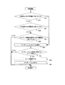
FIG. 18 is a flow chart illustrating processing for controlling the execution of migration based on statistical information by the
図18の例では、統計情報として、各サーバの空き容量1602、CPU負荷1604及びネットワーク帯域使用量1605が使用される。具体的には、これらの値と、予め設定された閾値とを比較し、その比較の結果に基づいて、マイグレーションの実行が制御される。
In the example of FIG. 18, the free capacity 1602, the
なお、以下に説明するステップ1801から1807までの処理は、マイグレーション元サーバリスト1650に表示された各サーバ110を対象として実行される。
Note that the processing from
管理計算機140のCPU144は、最初に、空き容量1602の値が所定の閾値を下回っているか否かを判定する(1801)。
The CPU 144 of the
ステップ1801において、閾値を下回っていると判定された場合(すなわち、「はい」の場合)、特定のLDEV124にデータが集中して格納されていると考えられる。この場合、LDEV124に格納されているデータ量を分散させるために、マイグレーションを実行することが望ましい。この場合、処理はステップ1804へ進む。
If it is determined in
この場合、CPU144はステップ1804において、空き容量1602の閾値を上回るために十分な使用容量1612を持つ一つ以上のマイグレーションポイントを選択する。
In this case, in
一方、ステップ1801において、閾値を下回っていないと判定された場合(すなわち、「いいえ」の場合)、処理はステップ1802へ進む。
On the other hand, if it is determined in
ステップ1802において、CPU144は、CPU負荷1604の値が所定の閾値を上回ったか否かを判定する。
In
ステップ1802において、閾値を上回っていると判定された場合(すなわち、「はい」の場合)、特定のサーバに処理の負荷が集中していると考えられる。この場合、サーバ110のCPU負荷を分散させるために、マイグレーションを実行することが望ましい。この場合、処理はステップ1804へ進む。
If it is determined in
この場合、CPU144はステップ1804において、クライアント150から各マイグレーションポイントへのアクセスによるCPU負荷を、readI/O情報1613及びwriteI/O情報1614に基づいて算出する。正確なCPU負荷を算出する代わりに、近似的な値を算出してもよい。そして、CPU144は、マイグレーションによってCPU負荷1604が閾値を下回るように、一つ以上の適切なマイグレーションポイントを選択する。
In this case, in
一方、ステップ1802において、閾値を上回っていないと判定された場合(すなわち、「いいえ」の場合)、処理はステップ1803へ進む。
On the other hand, if it is determined in
ステップ1803において、CPU144は、ネットワーク帯域1605の値(すなわち、ネットワーク帯域の使用量)が所定の閾値を上回ったか否かを判定する。
In
ステップ1803において、閾値を上回ったと判定された場合(すなわち、「はいの場合」)、特定のサーバに通信の負荷が集中していると考えられる。この場合、通信の負荷を分散させるために、マイグレーションを実行することが望ましい。この場合、処理はステップ1804へ進む。
If it is determined in
この場合、CPU144はステップ1804において、readバイト数1613及びwriteバイト数1614に基づいて、各マイグレーションポイントの単位時間当たりのネットワーク帯域の使用量を計算する。そして、CPU144は、その計算の結果に基づいて、ネットワーク帯域1605が閾値を下回るように、一つ以上の適切なマイグレーションポイントを選択する。
In this case, in
一方、ステップ1803において、閾値を上回っていないと判定された場合(すなわち、「いいえ」の場合)、データ量及び負荷のいずれも集中していない。この場合、マイグレーションを実行する必要がないため、処理を終了する。
On the other hand, if it is determined in
CPU144は、ステップ1804を実行した後、マイグレーションの条件に適合するサーバ110があるか否かを判定する(1805)。
After executing
具体的には、CPU144は、ステップ1804で選択されたマイグレーションポイントの数以上の空きLDEV数1623を持つサーバ110の中から、ステップ1804で選択されたマイグレーションポイントをマイグレーションしたとしても、次の三つの条件を満たすと予測されるサーバ110を選択する。
(1)空き容量1602が所定の閾値を下回らない。
(2)CPU負荷1604が所定の閾値を上回らない。
(3)ネットワーク帯域1605が所定の閾値を上回らない。
Specifically, even if the CPU 144 migrates the migration point selected in
(1) The free space 1602 does not fall below a predetermined threshold.
(2) The
(3) The
ステップ1805において、マイグレーションの条件に適合するサーバ110があると判定された場合、そのサーバ110へのマイグレーションを実行することによって、サーバ110の負荷等が分散される。このため、CPU144は、条件に適合するサーバ110をマイグレーション先として選択する(1806)。複数のサーバ110が条件に適合する場合、それらのうちの任意の数のサーバ110がマイグレーション先として選択されてもよい。
If it is determined in
次に、CPU144は、ステップ1804において選択されたマイグレーションポイントを、ステップ1806において選択されたサーバ110へマイグレーションする指示を、サーバ110に送信する(1807)。複数のマイグレーションポイントをマイグレーションする場合、全てのマイグレーションポイントを一つのサーバ110へマイグレーションしてもよいし、複数のサーバへ分散してマイグレーションしてもよい。ただし、複数のサーバ110全体で、選択されたマイグレーションポイントの数の空きLDEV数1623を用意することができ、かつ、全てのサーバが上記の条件(1)から(3)を満たす必要がある。
Next, the CPU 144 transmits to the server 110 an instruction to migrate the migration point selected in
一方、ステップ1805において、マイグレーションの条件に適合するサーバ110がないと判定された場合、マイグレーションを実行してもサーバ110の負荷等が分散されない。この場合、CPU144は、処理を終了する。
On the other hand, if it is determined in
以上の処理を実行することによって、全サーバ110の空き容量1602、CPU負荷1604、ネットワーク帯域1605を適切な範囲に保つことができる。
By executing the above processing, the free capacity 1602, the
また、各統計情報の履歴を取っておくことによって、次のような処理も実現できる。 In addition, the following processing can be realized by keeping a history of each statistical information.
例えば、各マイグレーションポイントの使用容量1612、readI/O情報1613及びwriteI/O情報1614の履歴を参照することによって、ほとんど読み込みにしか使っていないマイグレーションポイントであるか否かが分かる。ほとんど読み込みにしか使っていないマイグレーションポイントは、予めアーカイブ用途に適したLDEV124を持つサーバ110へマイグレーションされてもよい。
For example, by referring to the history of the
また、使用容量1612とwriteI/O情報1614の履歴を参照することによって、著しく使用容量が増加傾向にあるマイグレーションポイントを見つけることができる。このようなマイグレーションポイントは、特に空き容量1602が豊富で、書き込み性能の良いLDEV124を持つサーバ110へ予めマイグレーションすることもできる。
Further, by referring to the history of the
また、readI/Oバイト数1613及びwr iteI/Oバイト数1614の履歴を参照することによって、各マイグレーションポイントのネットワーク帯域の消費量が増加傾向にあるか否かが分かる。ネットワーク帯域の消費量が増加傾向にあるマイグレーションポイントは、特に大きいネットワーク帯域を持つサーバ110へ予めマイグレーションすることもできる。
Further, by referring to the history of the read I /
この他、短時間にマイグレーションを繰り返すことによってシステム全体の性能が低下することを避けるために、一度マイグレーションされたマイグレーションポイントは、しばらくマイグレーションを禁止することもできる。 In addition, in order to prevent the performance of the entire system from being deteriorated by repeating the migration in a short time, the migration point once migrated can be prohibited from migrating for a while.
サーバ110の統計情報(すなわち、マイグレーション元サーバリスト1650及びマイグレーション先サーバリスト1670に表示される情報)は、例えば、管理計算機140がマイグレーションのウィンドウを表示するときに取得してもよいし、周期的に取得してもよい。サーバ110間の通信には、LAN160が使用されてもよいし、サーバ間通信路135が使用されてもよい。
The statistical information of the server 110 (that is, information displayed in the migration
次に、上記の本発明の実施の形態の効果について説明する。 Next, effects of the above-described embodiment of the present invention will be described.
クライアントから透過的に、きめ細かいマイグレーションを実現する従来の方法として、予めストレージシステム100に少ない容量のファイルシステムを多数用意するという方法があった。以下、図19を参照して、本実施の形態と上記従来の方法とを比較する。
As a conventional method for realizing detailed migration transparently from a client, there is a method of preparing a large number of file systems with a small capacity in the
図19は、本発明の実施の形態と従来の手法とを比較する説明図である。 FIG. 19 is an explanatory diagram for comparing the embodiment of the present invention with a conventional method.
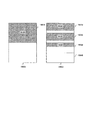
説明の便宜上、100GBの記憶容量を持つストレージシステム1900A及び1900Bがあると仮定する。ストレージシステム1900Aには本発明の実施の形態が適用され、ストレージシステム1900Bには従来の方法が適用される。ストレージシステム1900Aは、一つのファイルシステム1901Aのみを含む。すなわち、ファイルシステム1901Aの記憶容量は100GBである。一方、ストレージシステム1900Bには、予め小さいファイルシステムが用意される。具体的には、ストレージシステム1900Bは、各々の記憶容量が25GBである四つのファイルシステム1901B、1902B、1903B及び1904Bを含む。
For convenience of explanation, it is assumed that there are
ストレージシステム1900A及び1900Bに格納されているファイルのデータ量は、それぞれ50GBである。図19中の網掛けされている領域が、ストレージシステム1900A及び1900Bの使用領域(すなわち、ファイルを格納している領域)である。ストレージシステム1900Bでは、ファイルシステム1901B及び1902Bにそれぞれ20GBのデータが格納され、ファイルシステム1903Bには10GBのデータが格納され、ファイルシステム1904Bにはデータが格納されていない。
The data amount of the files stored in the
図19の例では、各ファイルシステムの使用率が80%になった時点で、マイグレーションが実行されると仮定する。ファイルシステムの使用率とは、各ファイルシステムに設定されている記憶容量に対する、実際に使用されている容量の割合(%)である。 In the example of FIG. 19, it is assumed that migration is performed when the usage rate of each file system reaches 80%. The usage rate of the file system is the ratio (%) of the capacity actually used to the storage capacity set for each file system.
以上の条件で、図19を参照すると、ストレージシステム1900Aでは、ファイルシステム1901Aの使用率が50%である。このため、マイグレーションを実行する必要が無い。これに対し、ストレージシステム1900Bでは、ファイルシステム1901B及び1902Bの使用率は、マイグレーションの閾値である80%である。このため、ファイルシステム1901B及び1902Bは、マイグレーションの対象となってしまう。このように、ファイルシステム1901B及び1902Bに格納されるファイルが集中している一方で、ファイルシステム1903B及び1904Bには、空き容量の余裕がある。ストレージシステム1900Bでは、マイグレーションの回数が増える上に、最初に割り当てられたファイルシステム1904Bが無駄になる可能性もあり、性能面においても、ストレージシステム100の使用効率においても無駄が多い。
With reference to FIG. 19 under the above conditions, in the
小さなファイルシステムを予め作成し、細かい粒度のマイグレーションを実現する従来の方法で、効率よくストレージシステム100を使用するためには、図19の例のようなことが起こらないように、予めファイルシステムごとの細かい運用計画を立てなければならない。しかしながら、実際にストレージシステム100の運用の前から細かい予測を立てることは難しい。
In order to efficiently use the
これに対して、本発明の実施の形態によれば、必要に応じてファイルシステムを分割してマイグレーションを実行することによって、ファイルシステム数を必要最小限に抑えることができる。このため、本実施の形態は、図19のストレージシステム1900Bに示す方法と比べ、マイグレーション処理の増加による性能劣化、及び、容量効率の無駄を抑える効果がある。
On the other hand, according to the embodiment of the present invention, the number of file systems can be suppressed to a necessary minimum by dividing the file system as necessary and executing the migration. For this reason, this embodiment has an effect of suppressing performance degradation due to an increase in migration processing and waste of capacity efficiency, as compared with the method shown in the
以上、本発明の実施の形態によれば、複数のサーバ110を備えるストレージシステム100において、ファイルシステムを分割することによって、きめ細かい粒度のマイグレーションを、クライアントから透過的に実現することが可能となる。これは、複数のサーバ110間のより良い負荷の均衡を可能とし、ストレージシステム100全体の性能向上に寄与する。
As described above, according to the embodiment of the present invention, in a
100 ストレージシステム
110 サーバ
111 ネットワークインターフェース
112 CPU
113 ローカルメモリ
116 アダプタ
120 ディスクサブシステム
121 ディスクコントローラ
122 ディスクキャッシュ
123 ディスクドライブ
124 論理デバイス(LDEV)
125 ポート
126 管理用ポート
130 スイッチ
131 管理用ポート
135 サーバ間通信路
140 管理計算機
150 クライアント
160 LAN
200 サーバソフトウェア
201 ネットワーク処理プログラム
202 ファイルシステム処理プログラム
203 ディスクアクセス処理プログラム
204 GNS管理処理プログラム
205 サーバ管理処理プログラム
206 サーバ間通信処理プログラム
207 マイグレーション処理プログラム
211 マイグレーションポイント設定処理モジュール
212 ファイルアクセス処理モジュール
213 ファイルシステム作成処理モジュール
214 ファイルシステム分割処理モジュール
100 storage system 110 server 111 network interface 112 CPU
113 Local memory 116
125
200
Claims (12)
前記複数のサーバは、第1サーバ及び第2サーバを含み、
前記各サーバは、ネットワークに接続されるインターフェースと、前記インターフェースに接続されるプロセッサと、前記プロセッサに接続されるメモリと、を備え、
前記ディスクサブシステムは、一つ以上のファイルシステムを含む一つ以上の論理デバイスを備え、
前記ファイルシステムに含まれるディレクトリのうち最上位のディレクトリには、前記ストレージシステム内で一意の第1のファイルシステム識別子が付与され、
前記ファイルシステムに含まれるディレクトリのうち前記最上位のディレクトリ以外の一つには、前記ストレージシステム内で一意の第2のファイルシステム識別子が付与され、
前記ファイルシステムに含まれるファイルには、前記ファイルシステム内で一意のファイル識別子が付与され、
前記第1サーバが備える前記プロセッサは、
前記第2のファイルシステム識別子が付与された前記ディレクトリより下位のファイルの名前解決を実行して、前記第2のファイルシステム識別子及び前記ファイル識別子を含むファイルハンドルを前記ネットワークに接続されたクライアント計算機に送信し、
前記クライアント計算機から前記第2のファイルシステム識別子及び前記ファイル識別子を含むファイルハンドルを指定したアクセス要求を受信すると、前記第2のファイルシステム識別子が付与された前記ディレクトリより下位の、前記ファイルハンドルによって指定されたファイル識別子が付与されたファイルにアクセスし、
前記第2のファイルシステム識別子が付与された前記ディレクトリを前記第2サーバへマイグレーションする指示を、前記インターフェースを介して受信すると、前記マイグレーションの対象の前記ディレクトリより下位の前記ファイルと、前記マイグレーションの対象の前記ディレクトリに付与された前記第2のファイルシステム識別子と、を前記第2サーバへ送信し、
前記第2サーバが備える前記プロセッサは、前記クライアント計算機から、前記第2のファイルシステム識別子及び前記ファイル識別子を含むファイルハンドルを指定したアクセス要求を受信すると、前記第2のファイルシステム識別子が付与された前記ディレクトリより下位の、前記ファイルハンドルによって指定されたファイル識別子が付与されたファイルにアクセスすることを特徴とするストレージシステム。 In a storage system comprising a plurality of servers and a disk subsystem connected to the plurality of servers,
The plurality of servers include a first server and a second server,
Each server includes an interface connected to a network, a processor connected to the interface, and a memory connected to the processor.
The disk subsystem comprises one or more logical devices including one or more file systems,
The highest directory among the directories included in the file system is given a first file system identifier that is unique within the storage system,
One of the directories included in the file system other than the top directory is given a second file system identifier that is unique within the storage system,
A file included in the file system is given a unique file identifier within the file system,
The processor included in the first server is:
Execute name resolution of a file lower than the directory to which the second file system identifier is assigned, and send a file handle including the second file system identifier and the file identifier to a client computer connected to the network Send
When an access request specifying the second file system identifier and the file handle including the file identifier is received from the client computer, the file handle is specified by the file handle below the directory to which the second file system identifier is assigned. Access the file with the assigned file identifier,
When an instruction to migrate the directory to which the second file system identifier is assigned to the second server is received via the interface, the file lower than the directory to be migrated and the migration target Sending the second file system identifier assigned to the directory to the second server,
When the processor included in the second server receives an access request designating a file handle including the second file system identifier and the file identifier from the client computer, the second file system identifier is assigned. A storage system for accessing a file assigned with a file identifier specified by the file handle, which is lower than the directory .
前記ストレージシステムは、複数のサーバと、前記複数のサーバに接続されるディスクサブシステムと、を備え、 The storage system comprises a plurality of servers and a disk subsystem connected to the plurality of servers,
前記複数のサーバは、第1サーバ及び第2サーバを含み、 The plurality of servers include a first server and a second server,
前記各サーバは、前記ネットワークに接続されるインターフェースと、前記インターフェースに接続されるプロセッサと、前記プロセッサに接続されるメモリと、を備え、 Each of the servers includes an interface connected to the network, a processor connected to the interface, and a memory connected to the processor.
前記ディスクサブシステムは、一つ以上のファイルシステムを含む一つ以上の論理デバイスを備え、 The disk subsystem comprises one or more logical devices including one or more file systems,
前記ファイルシステムに含まれるディレクトリのうち最上位のディレクトリには、前記ストレージシステム内で一意の第1のファイルシステム識別子が付与され、 The highest directory among the directories included in the file system is given a first file system identifier that is unique within the storage system,
前記ファイルシステムに含まれるディレクトリのうち前記最上位のディレクトリ以外の一つには、前記ストレージシステム内で一意の第2のファイルシステム識別子が付与され、 One of the directories included in the file system other than the top directory is given a second file system identifier that is unique within the storage system,
前記ファイルシステムに含まれるファイルには、前記ファイルシステム内で一意のファイル識別子が付与され、 A file included in the file system is given a unique file identifier within the file system,
前記第1サーバが備える前記プロセッサは、 The processor included in the first server is:
前記第2のファイルシステム識別子が付与された前記ディレクトリより下位のファイルの名前解決を実行して、前記第2のファイルシステム識別子及び前記ファイル識別子を含むファイルハンドルを前記クライアント計算機に送信し、 Performing name resolution of a file lower than the directory to which the second file system identifier is assigned, and sending a file handle including the second file system identifier and the file identifier to the client computer;
前記クライアント計算機から前記第2のファイルシステム識別子及び前記ファイル識別子を含むファイルハンドルを指定したアクセス要求を受信すると、前記第2のファイルシステム識別子が付与された前記ディレクトリより下位の、前記ファイルハンドルによって指定されたファイル識別子が付与されたファイルにアクセスし、 When an access request specifying the second file system identifier and the file handle including the file identifier is received from the client computer, the file handle is specified by the file handle below the directory to which the second file system identifier is assigned. Access the file with the assigned file identifier,
前記第2のファイルシステム識別子が付与された前記ディレクトリを前記第2サーバへマイグレーションする指示を、前記インターフェースを介して受信すると、前記マイグレーションの対象の前記ディレクトリより下位の前記ファイルと、前記マイグレーションの対象の前記ディレクトリに付与された前記第2のファイルシステム識別子と、を前記第2サーバへ送信し、 When an instruction to migrate the directory to which the second file system identifier is assigned to the second server is received via the interface, the file lower than the directory to be migrated and the migration target Sending the second file system identifier assigned to the directory to the second server,
前記第2サーバが備える前記プロセッサは、前記クライアント計算機から、前記第2のファイルシステム識別子及び前記ファイル識別子を含むファイルハンドルを指定したアクセス要求を受信すると、前記第2のファイルシステム識別子が付与された前記ディレクトリより下位の、前記ファイルハンドルによって指定されたファイル識別子が付与されたファイルにアクセスすることを特徴とする計算機システム。 When the processor included in the second server receives an access request designating a file handle including the second file system identifier and the file identifier from the client computer, the second file system identifier is assigned. A computer system accessing a file assigned with a file identifier specified by the file handle, which is lower than the directory.
前記管理計算機は、前記ネットワークに接続されるインターフェースと、前記インターフェースに接続されるプロセッサと、前記プロセッサに接続されるメモリと、を備え、 The management computer includes an interface connected to the network, a processor connected to the interface, and a memory connected to the processor,
前記計算機システムは、前記ディレクトリに既に付与された前記ファイルシステム識別子の値を管理する管理情報を保持し、 The computer system holds management information for managing the value of the file system identifier already assigned to the directory,
前記管理計算機が備える前記プロセッサは、前記管理情報を参照して、まだいずれの前記ディレクトリにも付与されていない値を、まだ前記ファイルシステム識別子を付与されていない前記ディレクトリに、前記ファイルシステム識別子として付与することを特徴とする請求項3に記載の計算機システム。 The processor included in the management computer refers to the management information and sets a value that has not been assigned to any of the directories as a file system identifier to the directory that has not yet been assigned the file system identifier. The computer system according to claim 3, wherein the computer system is assigned.
前記管理計算機は、前記ネットワークに接続されるインターフェースと、前記インターフェースに接続されるプロセッサと、前記プロセッサに接続されるメモリと、を備え、 The management computer includes an interface connected to the network, a processor connected to the interface, and a memory connected to the processor,
前記管理計算機が備える前記プロセッサは、ファイルアクセスに関する統計情報に基づいて、前記ディレクトリを対象とするマイグレーションを実行するか否かを判定することを特徴とする請求項3に記載の計算機システム。 4. The computer system according to claim 3, wherein the processor included in the management computer determines whether or not to execute migration for the directory based on statistical information regarding file access.
前記管理計算機が備える前記プロセッサは、前記第1サーバが備えるプロセッサの使用率が所定の閾値を越えた場合、前記第1サーバが管理する前記ファイルシステムに含まれ、かつ、前記ファイルシステム識別子が付与された前記ディレクトリを選択し、前記選択されたディレクトリを対象とするマイグレーションを実行する指示を前記第1サーバに送信することを特徴とする請求項6に記載の計算機システム。 The processor included in the management computer is included in the file system managed by the first server when the usage rate of the processor included in the first server exceeds a predetermined threshold, and is assigned the file system identifier. The computer system according to claim 6, wherein the selected directory is selected, and an instruction to execute migration for the selected directory is transmitted to the first server.
前記ストレージシステムは、第1サーバ及び第2サーバを含む複数のサーバと、前記複数のサーバに接続されるディスクサブシステムと、を備え、 The storage system includes a plurality of servers including a first server and a second server, and a disk subsystem connected to the plurality of servers,
前記各サーバは、前記ネットワークに接続されるインターフェースと、前記インターフェースに接続されるプロセッサと、前記プロセッサに接続されるメモリと、を備え、 Each of the servers includes an interface connected to the network, a processor connected to the interface, and a memory connected to the processor.
前記ディスクサブシステムは、一つ以上のファイルシステムを含む一つ以上の論理デバイスを備え、 The disk subsystem comprises one or more logical devices including one or more file systems,
前記ファイルシステムに含まれるディレクトリのうち最上位のディレクトリには、前記ストレージシステム内で一意の第1のファイルシステム識別子が付与され、 The highest directory among the directories included in the file system is given a first file system identifier that is unique within the storage system,
前記ファイルシステムに含まれるディレクトリのうち前記最上位のディレクトリ以外の一つには、前記ストレージシステム内で一意の第2のファイルシステム識別子が付与され、 One of the directories included in the file system other than the top directory is given a second file system identifier that is unique within the storage system,
前記ファイルシステムに含まれるファイルには、前記ファイルシステム内で一意のファイル識別子が付与され、 A file included in the file system is given a unique file identifier within the file system,
前記方法は、 The method
前記第1サーバが備える前記プロセッサが、前記第2のファイルシステム識別子が付与された前記ディレクトリより下位のファイルの名前解決を実行して、前記第2のファイルシステム識別子及び前記ファイル識別子を含むファイルハンドルを前記クライアント計算機に送信し、 A file handle including the second file system identifier and the file identifier, wherein the processor included in the first server performs name resolution of a file lower than the directory to which the second file system identifier is assigned. To the client computer,
前記第1サーバが備える前記プロセッサが、前記クライアント計算機から前記第2のファイルシステム識別子及び前記ファイル識別子を含むファイルハンドルを指定したアクセス要求を受信すると、前記第2のファイルシステム識別子が付与された前記ディレクトリより下位の、前記ファイルハンドルによって指定されたファイル識別子が付与されたファイルにアクセスし、 When the processor included in the first server receives an access request designating a file handle including the second file system identifier and the file identifier from the client computer, the second file system identifier is added. Access a file with a file identifier specified by the file handle below the directory,
前記第1サーバが備える前記プロセッサが、前記第2のファイルシステム識別子が付与された前記ディレクトリを前記第2サーバへマイグレーションする指示を、前記インターフェースを介して受信すると、前記マイグレーションの対象の前記ディレクトリより下位の前記ファイルと、前記マイグレーションの対象の前記ディレクトリに付与された前記第2のファイルシステム識別子と、を前記第2サーバへ送信し、 When the processor included in the first server receives an instruction to migrate the directory to which the second file system identifier is assigned to the second server via the interface, the processor from the migration target directory Sending the lower file and the second file system identifier assigned to the migration target directory to the second server;
前記第2サーバが備える前記プロセッサが、前記クライアント計算機から、前記第2のファイルシステム識別子及び前記ファイル識別子を含むファイルハンドルを指定したアクセス要求を受信すると、前記第2のファイルシステム識別子が付与された前記ディレクトリより下位の、前記ファイルハンドルによって指定されたファイル識別子が付与されたファイルにアクセスすることを特徴とする方法。 When the processor included in the second server receives an access request specifying the second file system identifier and a file handle including the file identifier from the client computer, the second file system identifier is assigned. A method of accessing a file provided with a file identifier specified by the file handle below the directory.
前記管理計算機は、前記ネットワークに接続されるインターフェースと、前記インターフェースに接続されるプロセッサと、前記プロセッサに接続されるメモリと、を備え、 The management computer includes an interface connected to the network, a processor connected to the interface, and a memory connected to the processor,
前記計算機システムは、前記ディレクトリに既に付与された前記ファイルシステム識別子の値を管理する管理情報を保持し、 The computer system holds management information for managing the value of the file system identifier already assigned to the directory,
前記方法は、前記管理計算機が備える前記プロセッサが、前記管理情報を参照して、まだいずれの前記ディレクトリにも付与されていない値を、まだ前記ファイルシステム識別子を付与されていない前記ディレクトリに、前記ファイルシステム識別子として付与することを特徴とする請求項8に記載の方法。 In the method, the processor included in the management computer refers to the management information and assigns a value not yet assigned to any of the directories to the directory that has not yet been assigned the file system identifier. The method according to claim 8, wherein the method is provided as a file system identifier.
前記管理計算機は、前記ネットワークに接続されるインターフェースと、前記インターフェースに接続されるプロセッサと、前記プロセッサに接続されるメモリと、を備え、 The management computer includes an interface connected to the network, a processor connected to the interface, and a memory connected to the processor,
前記方法は、前記管理計算機が備える前記プロセッサが、ファイルアクセスに関する統計情報に基づいて、前記ディレクトリを対象とするマイグレーションを実行するか否かを判定することを特徴とする請求項8に記載の方法。 9. The method according to claim 8, wherein the processor of the management computer determines whether to execute migration for the directory based on statistical information regarding file access. .
前記方法は、前記管理計算機が備える前記プロセッサが、前記第1サーバが備えるプロセッサの使用率が所定の閾値を越えた場合、前記第1サーバが管理する前記ファイルシステムに含まれ、かつ、前記ファイルシステム識別子が付与された前記ディレクトリを選択し、前記選択されたディレクトリを対象とするマイグレーションを実行する指示を前記第1サーバに送信することを特徴とする請求項11に記載の方法。 The method is included in the file system managed by the first server when the processor of the management computer has a usage rate of the processor of the first server exceeding a predetermined threshold, and the file 12. The method according to claim 11, wherein the directory to which a system identifier is assigned is selected, and an instruction to execute migration for the selected directory is transmitted to the first server.
Priority Applications (4)
| Application Number | Priority Date | Filing Date | Title |
|---|---|---|---|
| JP2006106255A JP4772569B2 (en) | 2006-04-07 | 2006-04-07 | System and method for performing directory unit migration in a common namespace |
| US11/477,858 US7587436B2 (en) | 2006-04-07 | 2006-06-30 | Method and system for executing directory-basis migration in a global name space |
| EP06255623A EP1843245A3 (en) | 2006-04-07 | 2006-11-01 | Method and system for executing directory-basis migration in a global name space |
| CN200610168701A CN100576189C (en) | 2006-04-07 | 2006-12-19 | Directory unit migration in GNS |
Applications Claiming Priority (1)
| Application Number | Priority Date | Filing Date | Title |
|---|---|---|---|
| JP2006106255A JP4772569B2 (en) | 2006-04-07 | 2006-04-07 | System and method for performing directory unit migration in a common namespace |
Publications (2)
| Publication Number | Publication Date |
|---|---|
| JP2007280099A JP2007280099A (en) | 2007-10-25 |
| JP4772569B2 true JP4772569B2 (en) | 2011-09-14 |
Family
ID=38180274
Family Applications (1)
| Application Number | Title | Priority Date | Filing Date |
|---|---|---|---|
| JP2006106255A Expired - Fee Related JP4772569B2 (en) | 2006-04-07 | 2006-04-07 | System and method for performing directory unit migration in a common namespace |
Country Status (4)
| Country | Link |
|---|---|
| US (1) | US7587436B2 (en) |
| EP (1) | EP1843245A3 (en) |
| JP (1) | JP4772569B2 (en) |
| CN (1) | CN100576189C (en) |
Cited By (1)
| Publication number | Priority date | Publication date | Assignee | Title |
|---|---|---|---|---|
| US10289603B2 (en) | 2012-10-12 | 2019-05-14 | Amazon Technologies, Inc. | Dynamic search partitioning |
Families Citing this family (46)
| Publication number | Priority date | Publication date | Assignee | Title |
|---|---|---|---|---|
| US8745106B2 (en) * | 2006-08-30 | 2014-06-03 | Red Hat, Inc. | Numeric identifier assignment in a networked computer environment |
| TW200925858A (en) * | 2007-12-06 | 2009-06-16 | Ind Tech Res Inst | Virtual file managing system and method for building system configuration and accessing file thereof |
| US20090319736A1 (en) * | 2008-06-24 | 2009-12-24 | Hitachi, Ltd. | Method and apparatus for integrated nas and cas data backup |
| JP2010108409A (en) * | 2008-10-31 | 2010-05-13 | Hitachi Ltd | Storage management method and management server |
| US8135912B2 (en) | 2009-05-18 | 2012-03-13 | Hola Networks, Ltd. | System and method of increasing cache size |
| US8560604B2 (en) | 2009-10-08 | 2013-10-15 | Hola Networks Ltd. | System and method for providing faster and more efficient data communication |
| US8484259B1 (en) | 2009-12-08 | 2013-07-09 | Netapp, Inc. | Metadata subsystem for a distributed object store in a network storage system |
| US9507799B1 (en) * | 2009-12-08 | 2016-11-29 | Netapp, Inc. | Distributed object store for network-based content repository |
| US8180813B1 (en) | 2009-12-08 | 2012-05-15 | Netapp, Inc. | Content repository implemented in a network storage server system |
| US20110137966A1 (en) * | 2009-12-08 | 2011-06-09 | Netapp, Inc. | Methods and systems for providing a unified namespace for multiple network protocols |
| US9063666B2 (en) * | 2010-03-25 | 2015-06-23 | International Business Machines Corporation | File index, metadata storage, and file system management for magnetic tape |
| US9275678B2 (en) * | 2010-03-25 | 2016-03-01 | International Business Machines Corporation | Primary storage media with associated secondary storage media for efficient data management |
| US9430155B2 (en) * | 2010-03-25 | 2016-08-30 | International Business Machines Corporation | File index, metadata storage, and file system management for magnetic tape |
| EP2652620B1 (en) | 2010-12-14 | 2015-06-17 | Hitachi, Ltd. | Failure recovery method in information processing system and corresponding information processing system |
| US8856073B2 (en) | 2010-12-14 | 2014-10-07 | Hitachi, Ltd. | Data synchronization among file storages using stub files |
| IL210169A0 (en) | 2010-12-22 | 2011-03-31 | Yehuda Binder | System and method for routing-based internet security |
| US8869136B2 (en) * | 2011-01-05 | 2014-10-21 | International Business Machines Corporation | Calculating migration points for application migration |
| EP2535826A1 (en) * | 2011-05-31 | 2012-12-19 | Research In Motion Limited | Method and system for data synchronization including file system abstraction |
| JP5816303B2 (en) * | 2011-09-13 | 2015-11-18 | 株式会社日立製作所 | Storage system including flash memory and storage control method |
| JP5735124B2 (en) * | 2011-10-28 | 2015-06-17 | 株式会社日立製作所 | Storage system and object management method |
| US9043567B1 (en) * | 2012-03-28 | 2015-05-26 | Netapp, Inc. | Methods and systems for replicating an expandable storage volume |
| KR101782302B1 (en) * | 2012-10-12 | 2017-09-26 | 에이나인.컴, 인크. | Index configuration for searchable data in network |
| US9460097B2 (en) | 2013-07-02 | 2016-10-04 | Hitachi Data Systems Engineering UK Limited | Method and apparatus for migration of a virtualized file system, data storage system for migration of a virtualized file system, and file server for use in a data storage system |
| CN105593804B (en) | 2013-07-02 | 2019-02-22 | 日立数据系统工程英国有限公司 | Method and apparatus for file system virtualization, data storage system for file system virtualization, and file server for data storage system |
| EP2836902B1 (en) | 2013-07-02 | 2018-12-26 | Hitachi Data Systems Engineering UK Limited | Method and apparatus for migration of a virtualized file system, data storage system for migration of a virtualized file system, and file server for use in a data storage system |
| US9241044B2 (en) | 2013-08-28 | 2016-01-19 | Hola Networks, Ltd. | System and method for improving internet communication by using intermediate nodes |
| JP5681783B2 (en) * | 2013-12-26 | 2015-03-11 | 株式会社日立製作所 | Failure recovery method in information processing system and information processing system |
| US20150220438A1 (en) * | 2014-02-04 | 2015-08-06 | Netapp, Inc. | Dynamic hot volume caching |
| US11023846B2 (en) | 2015-04-24 | 2021-06-01 | United Parcel Service Of America, Inc. | Location-based pick up and delivery services |
| US11057446B2 (en) | 2015-05-14 | 2021-07-06 | Bright Data Ltd. | System and method for streaming content from multiple servers |
| CN105897457A (en) * | 2015-12-09 | 2016-08-24 | 乐视云计算有限公司 | Service upgrade method and system of server group |
| US10474629B2 (en) * | 2016-09-28 | 2019-11-12 | Elastifile Ltd. | File systems with global and local naming |
| US10579598B2 (en) | 2017-01-03 | 2020-03-03 | International Business Machines Corporation | Global namespace for a hierarchical set of file systems |
| US10649955B2 (en) | 2017-01-03 | 2020-05-12 | International Business Machines Corporation | Providing unique inodes across multiple file system namespaces |
| US10585860B2 (en) | 2017-01-03 | 2020-03-10 | International Business Machines Corporation | Global namespace for a hierarchical set of file systems |
| US10579587B2 (en) | 2017-01-03 | 2020-03-03 | International Business Machines Corporation | Space management for a hierarchical set of file systems |
| US10592479B2 (en) | 2017-01-03 | 2020-03-17 | International Business Machines Corporation | Space management for a hierarchical set of file systems |
| US10657102B2 (en) | 2017-01-03 | 2020-05-19 | International Business Machines Corporation | Storage space management in union mounted file systems |
| US11190374B2 (en) | 2017-08-28 | 2021-11-30 | Bright Data Ltd. | System and method for improving content fetching by selecting tunnel devices |
| LT3767494T (en) | 2017-08-28 | 2023-03-10 | Bright Data Ltd. | Method for improving content fetching by selecting tunnel devices |
| EP3780557B1 (en) | 2019-02-25 | 2023-02-15 | Bright Data Ltd. | System and method for url fetching retry mechanism |
| EP4383686A1 (en) | 2019-04-02 | 2024-06-12 | Bright Data Ltd. | System and method for managing non-direct url fetching service |
| CN114691015A (en) * | 2020-12-29 | 2022-07-01 | 华为技术有限公司 | Storage system management method, storage system and computer program product |
| CN115774703A (en) | 2021-09-08 | 2023-03-10 | 华为技术有限公司 | Information processing method and device |
| JP2023079863A (en) * | 2021-11-29 | 2023-06-08 | キヤノン株式会社 | Data migration support system and migration method |
| CN114816571B (en) * | 2022-04-15 | 2023-06-16 | 西安广和通无线通信有限公司 | Method, device, equipment and storage medium for plug-in flash memory |
Family Cites Families (6)
| Publication number | Priority date | Publication date | Assignee | Title |
|---|---|---|---|---|
| US6671773B2 (en) | 2000-12-07 | 2003-12-30 | Spinnaker Networks, Llc | Method and system for responding to file system requests |
| JP4168626B2 (en) * | 2001-12-06 | 2008-10-22 | 株式会社日立製作所 | File migration method between storage devices |
| US6985914B2 (en) | 2002-02-20 | 2006-01-10 | Emc Corporation | Cluster meta file system of file system cells managed by respective data movers of a network file server |
| US7886299B2 (en) * | 2004-06-01 | 2011-02-08 | Hitachi, Ltd. | Method of dynamically balancing workload of a storage system |
| JP4281658B2 (en) * | 2004-09-24 | 2009-06-17 | 日本電気株式会社 | File access service system, switching device, quota management method and program |
| JP4451293B2 (en) * | 2004-12-10 | 2010-04-14 | 株式会社日立製作所 | Network storage system of cluster configuration sharing name space and control method thereof |
-
2006
- 2006-04-07 JP JP2006106255A patent/JP4772569B2/en not_active Expired - Fee Related
- 2006-06-30 US US11/477,858 patent/US7587436B2/en not_active Expired - Fee Related
- 2006-11-01 EP EP06255623A patent/EP1843245A3/en not_active Withdrawn
- 2006-12-19 CN CN200610168701A patent/CN100576189C/en not_active Expired - Fee Related
Cited By (1)
| Publication number | Priority date | Publication date | Assignee | Title |
|---|---|---|---|---|
| US10289603B2 (en) | 2012-10-12 | 2019-05-14 | Amazon Technologies, Inc. | Dynamic search partitioning |
Also Published As
| Publication number | Publication date |
|---|---|
| JP2007280099A (en) | 2007-10-25 |
| US7587436B2 (en) | 2009-09-08 |
| CN100576189C (en) | 2009-12-30 |
| EP1843245A3 (en) | 2009-10-21 |
| CN101051290A (en) | 2007-10-10 |
| EP1843245A2 (en) | 2007-10-10 |
| US20070239655A1 (en) | 2007-10-11 |
Similar Documents
| Publication | Publication Date | Title |
|---|---|---|
| JP4772569B2 (en) | System and method for performing directory unit migration in a common namespace | |
| US8161133B2 (en) | Network storage system with a clustered configuration sharing a namespace, and control method therefor | |
| US8566548B2 (en) | Volume selection method and information processing system | |
| JP4943081B2 (en) | File storage control device and method | |
| JP4836533B2 (en) | File system migration method in storage system, storage system, and management computer | |
| US11409454B1 (en) | Container ownership protocol for independent node flushing | |
| US8271559B2 (en) | Storage system and method of controlling same | |
| US20100100678A1 (en) | Volume management system | |
| US10162527B2 (en) | Scalable and efficient access to and management of data and resources in a tiered data storage system | |
| US8423713B2 (en) | Cluster type storage system and method of controlling the same | |
| US9766822B2 (en) | Computer system and its renewal method | |
| US20070192375A1 (en) | Method and computer system for updating data when reference load is balanced by mirroring | |
| US10019182B2 (en) | Management system and management method of computer system | |
| US10089125B2 (en) | Virtual machines accessing file data, object data, and block data | |
| JP5543653B2 (en) | Management computer | |
| JP5746397B2 (en) | Management computer and renewal method | |
| JP2015164065A (en) | Management computer and renewal method |
Legal Events
| Date | Code | Title | Description |
|---|---|---|---|
| A621 | Written request for application examination |
Free format text: JAPANESE INTERMEDIATE CODE: A621 Effective date: 20080819 |
|
| A131 | Notification of reasons for refusal |
Free format text: JAPANESE INTERMEDIATE CODE: A131 Effective date: 20110301 |
|
| A521 | Request for written amendment filed |
Free format text: JAPANESE INTERMEDIATE CODE: A523 Effective date: 20110427 |
|
| A01 | Written decision to grant a patent or to grant a registration (utility model) |
Free format text: JAPANESE INTERMEDIATE CODE: A01 Effective date: 20110524 |
|
| A61 | First payment of annual fees (during grant procedure) |
Free format text: JAPANESE INTERMEDIATE CODE: A61 Effective date: 20110622 |
|
| FPAY | Renewal fee payment (event date is renewal date of database) |
Free format text: PAYMENT UNTIL: 20140701 Year of fee payment: 3 |
|
| R150 | Certificate of patent or registration of utility model |
Free format text: JAPANESE INTERMEDIATE CODE: R150 |
|
| LAPS | Cancellation because of no payment of annual fees |