JP4762735B2 - Wireless communication apparatus, communication path control apparatus, communication path control method, and communication system - Google Patents
Wireless communication apparatus, communication path control apparatus, communication path control method, and communication system Download PDFInfo
- Publication number
- JP4762735B2 JP4762735B2 JP2006019461A JP2006019461A JP4762735B2 JP 4762735 B2 JP4762735 B2 JP 4762735B2 JP 2006019461 A JP2006019461 A JP 2006019461A JP 2006019461 A JP2006019461 A JP 2006019461A JP 4762735 B2 JP4762735 B2 JP 4762735B2
- Authority
- JP
- Japan
- Prior art keywords
- wireless
- interfaces
- request frame
- communication
- node
- Prior art date
- Legal status (The legal status is an assumption and is not a legal conclusion. Google has not performed a legal analysis and makes no representation as to the accuracy of the status listed.)
- Expired - Fee Related
Links
Images


Classifications
-
- H—ELECTRICITY
- H04—ELECTRIC COMMUNICATION TECHNIQUE
- H04W—WIRELESS COMMUNICATION NETWORKS
- H04W40/00—Communication routing or communication path finding
- H04W40/24—Connectivity information management, e.g. connectivity discovery or connectivity update
- H04W40/28—Connectivity information management, e.g. connectivity discovery or connectivity update for reactive routing
-
- H—ELECTRICITY
- H04—ELECTRIC COMMUNICATION TECHNIQUE
- H04L—TRANSMISSION OF DIGITAL INFORMATION, e.g. TELEGRAPHIC COMMUNICATION
- H04L45/00—Routing or path finding of packets in data switching networks
-
- H—ELECTRICITY
- H04—ELECTRIC COMMUNICATION TECHNIQUE
- H04L—TRANSMISSION OF DIGITAL INFORMATION, e.g. TELEGRAPHIC COMMUNICATION
- H04L45/00—Routing or path finding of packets in data switching networks
- H04L45/26—Route discovery packet
-
- H—ELECTRICITY
- H04—ELECTRIC COMMUNICATION TECHNIQUE
- H04L—TRANSMISSION OF DIGITAL INFORMATION, e.g. TELEGRAPHIC COMMUNICATION
- H04L45/00—Routing or path finding of packets in data switching networks
- H04L45/52—Multiprotocol routers
-
- H—ELECTRICITY
- H04—ELECTRIC COMMUNICATION TECHNIQUE
- H04W—WIRELESS COMMUNICATION NETWORKS
- H04W40/00—Communication routing or communication path finding
- H04W40/02—Communication route or path selection, e.g. power-based or shortest path routing
- H04W40/04—Communication route or path selection, e.g. power-based or shortest path routing based on wireless node resources
-
- H—ELECTRICITY
- H04—ELECTRIC COMMUNICATION TECHNIQUE
- H04W—WIRELESS COMMUNICATION NETWORKS
- H04W84/00—Network topologies
- H04W84/18—Self-organising networks, e.g. ad-hoc networks or sensor networks
-
- H—ELECTRICITY
- H04—ELECTRIC COMMUNICATION TECHNIQUE
- H04W—WIRELESS COMMUNICATION NETWORKS
- H04W92/00—Interfaces specially adapted for wireless communication networks
- H04W92/02—Inter-networking arrangements
Landscapes
- Engineering & Computer Science (AREA)
- Computer Networks & Wireless Communication (AREA)
- Signal Processing (AREA)
- Mobile Radio Communication Systems (AREA)
- Data Exchanges In Wide-Area Networks (AREA)
Abstract
Description
本発明は、複数の無線通信装置間を無線回線により相互接続し、自律的に通信経路を確立するアドホックネットワークに関し、特に、複数の無線インターフェイスを有する無線通信装置がそのインターフェイスを自律的に切り替えることで、無線リソースの有効活用を図る無線通信装置、通信経路制御装置、通信経路制御方法及び通信システムに関する。 The present invention relates to an ad hoc network in which a plurality of wireless communication devices are interconnected by a wireless line and autonomously establish a communication path, and in particular, a wireless communication device having a plurality of wireless interfaces autonomously switches the interface. Thus, the present invention relates to a wireless communication apparatus, a communication path control apparatus, a communication path control method, and a communication system that effectively use radio resources.
無線アドホックネットワークは、特定の集中制御局を持たず、無線通信装置が対等な立場で情報交換を行なうことで、自律的に通信経路を確保し、ネットワークを構成する技術である。アドホックネットワークにおける経路制御は2つの方式に大別できる。一方は距離ベクトル型であり、他方はリンクステート型である。 The wireless ad hoc network is a technology that does not have a specific centralized control station, and wireless communication apparatuses exchange information from an equal standpoint to autonomously secure a communication path and configure the network. Path control in an ad hoc network can be roughly divided into two methods. One is a distance vector type and the other is a link state type.
本発明は、上記2つの方式のうち、AODV(Ad hoc On-Demand Distance Vector Routing)やDSR(Dynamic Source Routing)やSTP(Spanning Tree Protocol)に代表される距離ベクトル型(非特許文献1、2、3)に関するものである。
The present invention is a distance vector type represented by AODV (Ad hoc On-Demand Distance Vector Routing), DSR (Dynamic Source Routing) and STP (Spanning Tree Protocol) among the above two methods (
従来の距離ベクトル型アルゴリズムにおける経路制御方式を図1に示す。距離ベクトル型アルゴリズムは、送信元ノードがリクエストフレームを広告し、宛先ノードがリクエストフレームの応答信号として経路確認フレームを送信することから構成される。 A route control method in a conventional distance vector type algorithm is shown in FIG. The distance vector type algorithm is configured by a transmission source node advertising a request frame and a destination node transmitting a route confirmation frame as a response signal of the request frame.
リクエストフレームを受信した中間ノードは、リクエストフレーム内に記載された距離(通信コスト)を記憶しておき、より小さい通信コストが記載されたフレームのみを転送する。この動作を繰り返すことによって、宛先ノードは、送信元ノードからの通信コストが最小となる経路を知ることができる。最適な経路を記憶した宛先ノードは、記憶した経路の逆順を辿って経路確認フレームを送信する。この経路確認フレームの通過ルートが、送信元ノードから宛先ノードまでの最適経路になる。 The intermediate node that has received the request frame stores the distance (communication cost) described in the request frame, and transfers only the frame in which the smaller communication cost is described. By repeating this operation, the destination node can know the route that minimizes the communication cost from the transmission source node. The destination node storing the optimum route transmits a route confirmation frame in the reverse order of the stored route. The passage route of this route confirmation frame is the optimum route from the transmission source node to the destination node.
アドホックネットワークでは、端末が自律的にネットワークを構成する。そのため、ある特定の端末にトラヒックが集中すると、その端末を経由してデータのやり取りを行う端末すべてに関して、通信の遅延が発生する。 In an ad hoc network, terminals autonomously form a network. For this reason, when traffic concentrates on a specific terminal, a communication delay occurs for all terminals that exchange data via that terminal.
これを解決する手段として、特開2000−69046(特許文献1)では、有線ネットワークで用いられているスパニングツリーの概念を無線ネットワークに適用することが提案されている。更に、無線ネットワークでスパニングツリーを構築する際に、中継のループ発生を回避し、できるだけ無駄な中継を行わないような仕組みも提案されている(例えば、特許文献2及び3参照)。
As means for solving this, Japanese Patent Laid-Open No. 2000-69046 (Patent Document 1) proposes to apply the concept of spanning tree used in a wired network to a wireless network. Furthermore, when a spanning tree is constructed in a wireless network, a mechanism that avoids occurrence of relay loops and prevents unnecessary relays as much as possible has been proposed (see, for example,
また、特定ノードへの負荷集中による影響を回避するために、アドホックネットワークにおいてノードの負荷を指標として経路制御を行う提案が行われている(例えば、非特許文献4及び5参照)。その他に、ノード間の通信可能時間であるリンクコストと、ノードのビジー割合であるノードコストを、ネットワークのトラヒックの状況に応じて切り替える方法が提案されている(例えば、非特許文献6参照)。
In addition, in order to avoid the influence of load concentration on a specific node, proposals have been made to perform path control using the node load as an index in an ad hoc network (for example, see Non-Patent
しかしながら、これらの技術において、無線通信装置が保持する無線インターフェイスは単一である。したがって、複数の無線インターフェイスを保持している場合には、更なる改善が求められる。 However, in these technologies, the wireless communication device holds a single wireless interface. Therefore, when a plurality of wireless interfaces are held, further improvement is required.
一方、複数の無線インターフェイスを保持している場合に、干渉を低減して無線リソースを効率的に利用することが提案されている(例えば、非特許文献7参照)が、ノードへの負荷の集中について検討されていない。
上述したように、従来の技術では、複数の無線インターフェイスを効率的に利用しながら、ノードへの負荷集中を回避することが実現されていない、という問題があった。 As described above, the conventional technology has a problem that it is not realized to avoid load concentration on the node while efficiently using a plurality of wireless interfaces.
本発明は、前述のような従来技術の実情に鑑みてなされたものであり、複数の無線インターフェイスを考慮した最適な経路選択により、無線リソースの有効活用を図ることを目的とする。 The present invention has been made in view of the above-described situation of the prior art, and an object of the present invention is to effectively use radio resources by optimal route selection in consideration of a plurality of radio interfaces.
本発明の前記の目的は、無線アドホックネットワークにおいて複数の無線インターフェイスを介して通信する無線通信装置であって、フレームを蓄積する複数の送信バッファを前記複数の無線インターフェイス毎に有し、前記無線インターフェイス毎の前記複数の送信バッファに蓄積されたフレームの総データ量を前記複数の無線インターフェイス毎に測定する測定部と、前記複数の無線インターフェイスのうちの1つでリクエストフレームを受信すると、各無線インターフェイス間の前記測定部で測定した総データ量測定値の差が閾値未満の場合に、前記複数の無線インターフェイスのうち少なくとも2つの無線インターフェイスから前記リクエストフレームを送信し、各無線インターフェイス間の前記測定部で測定した総データ量測定値の差のうち少なくとも1つの差が閾値以上の場合に、該総データ量の少ない方の無線インターフェイスから前記リクエストフレームを送信するデータ送受信部と、前記リクエストフレームに基づいて、前記複数の無線インターフェイスのうちから通信を行う無線インターフェイスを選択するルーティング部とを有する無線通信装置、より解決することができる。 The object of the present invention is a wireless communication apparatus that communicates via a plurality of wireless interfaces in a wireless ad hoc network, and has a plurality of transmission buffers for storing frames for each of the plurality of wireless interfaces. A measurement unit that measures a total data amount of frames accumulated in each of the plurality of transmission buffers for each of the plurality of radio interfaces; and when a request frame is received by one of the plurality of radio interfaces, And when the difference between the total data amount measurement values measured by the measurement unit is less than a threshold value, the request frame is transmitted from at least two radio interfaces among the plurality of radio interfaces, and the measurement unit between the radio interfaces Measured value of total data measured with In the case of more than at least one difference threshold of the difference, the data transmission and reception unit that transmits the request frame from a wireless interface having the smaller said total data amount, based on the request frame, among the plurality of wireless interfaces The wireless communication device having a routing unit for selecting a wireless interface for performing communication from the wireless communication device can be further solved.
前記ルーティング部は、前記リクエストフレームの到着順序に基づいて、前記複数の無線インターフェイスのうちから通信を行う無線インターフェイスを選択してもよい。 The routing unit may select a wireless interface for communication from the plurality of wireless interfaces based on the arrival order of the request frames.
この無線装置により、複数の無線インターフェイスを考慮した最適な経路選択により、無線リソースの有効活用を図ることができる。 With this radio apparatus, it is possible to effectively use radio resources by optimal route selection in consideration of a plurality of radio interfaces.
前記ルーティング部は、前記リクエストフレームの到着順序と通信コストとに基づいて、前記複数の無線インターフェイスのうちから通信を行う無線インターフェイスを選択してもよい。 The routing unit may select a wireless interface for performing communication from the plurality of wireless interfaces based on an arrival order of the request frames and a communication cost.
この無線通信装置では、後から到着したリクエストフレームであっても通信コストの値が小さければ、その経路を選択することができる。結果として、複数の無線インターフェイスを考慮した最適な経路選択により、無線リソースの有効活用を図ることができる。 In this wireless communication apparatus, even if a request frame arrives later, the route can be selected if the communication cost value is small. As a result, effective utilization of radio resources can be achieved by optimal route selection considering a plurality of radio interfaces.
前記ルーティング部は、前記リクエストフレームの到着時間から一定の期間内に受信したリクエストフレームの通信コストに基づいて、前記複数の無線インターフェイスのうちから通信を行う無線インターフェイスを選択してもよい。 The routing unit may select a wireless interface for communication from the plurality of wireless interfaces based on a communication cost of a request frame received within a certain period from an arrival time of the request frame.
この通信装置では、遅延を一定の期間に抑えることができ、複数の無線インターフェイスを考慮した最適な経路選択により、無線リソースの有効活用を図ることができる。 In this communication apparatus, the delay can be suppressed to a certain period, and effective use of radio resources can be achieved by optimal route selection considering a plurality of radio interfaces .
この無線通信装置では、送信バッファのデータ蓄積量の小さい無線インターフェイスからリクエストフレームを送信することができ、無線インターフェイス使用率の均一化を図ることができる。結果として、複数の無線インターフェイスを考慮した最適な経路選択により、無線リソースの有効活用を図ることができる。 In this wireless communication apparatus, a request frame can be transmitted from a wireless interface with a small amount of data stored in the transmission buffer, and the wireless interface usage rate can be made uniform. As a result, effective utilization of radio resources can be achieved by optimal route selection considering a plurality of radio interfaces.
この無線通信装置では、送信バッファのデータ蓄積量の差に応じてリクエストフレームを送信する。このリクエストフレームの送信の選択により、1つのノード内での無線インターフェイスの均一性が保たれると同時に、周辺ノードとの周波数利用の均一性が維持できる。結果として、無線リソースの有効活用を図ることができる。 In this wireless communication device, a request frame is transmitted according to the difference in the data accumulation amount of the transmission buffer. By selecting the transmission of the request frame, the uniformity of the radio interface within one node can be maintained, and at the same time, the uniformity of frequency utilization with the peripheral nodes can be maintained. As a result, it is possible to effectively use radio resources.
前記無線通信装置は、配下の端末を管理するアクセスポイントとして機能してもよく、前記データ送受信部は、前記配下の端末からフレームを受信すると、該配下の端末に代わって前記リクエストフレームを送信してもよい。 The wireless communication apparatus may function as an access point for managing a terminal under its control, and when the data transmission / reception unit receives a frame from the terminal under the control, the data transmission / reception unit transmits the request frame on behalf of the terminal under the control. May be.
前記データ送受信部は、前記配下の端末宛てのリクエストフレームを受信すると、該配下の端末に代わって該リクエストフレームの応答信号を返信してもよい。 When the data transmission / reception unit receives a request frame addressed to the subordinate terminal, the data transmission / reception unit may return a response signal of the request frame on behalf of the subordinate terminal.
この無線通信装置によれば、端末がアドホック経路制御機能を有していなくても、送信元端末から宛先端末までの経路の確保が可能となる。 According to this wireless communication apparatus, it is possible to secure a route from a transmission source terminal to a destination terminal even if the terminal does not have an ad hoc route control function.
前記無線通信装置は、配下の端末が所属する所属端末情報を管理する所属端末管理部を更に有し、前記データ送受信部は、前記無線通信装置の配下に新たな端末が所属したときに、該端末の所属を通知するフレームをブロードキャスト送信し、前記所属端末管理部は、新たな端末の所属を通知するフレームを他の無線通信装置から受信すると、該端末の所属を前記所属端末情報から削除してもよい。 The wireless communication device further includes an affiliated terminal management unit that manages affiliated terminal information to which a subordinate terminal belongs, and the data transmission / reception unit is configured such that when a new terminal belongs to the wireless communication device, When a frame notifying the affiliation of a terminal is broadcast and the affiliation terminal management unit receives a frame notifying the affiliation of a new terminal from another wireless communication device, the affiliation terminal management unit deletes the affiliation of the terminal from the affiliation terminal information. May be.
この無線通信装置によれば、端末の移動に対しても対応することが可能となる。 According to this wireless communication apparatus, it is possible to cope with the movement of the terminal.
また、IEEE802.11以外のインターフェイスを介して有線通信装置等が接続されている場合にも対応することが可能になる。 Further, it is possible to cope with a case where a wired communication device or the like is connected via an interface other than IEEE 802.11.
前記ルーティング部は、送信元アドレス及び宛先アドレスの組毎に、前記複数の無線インターフェイスのうちから通信を行う無線インターフェイスを選択してもよい。 The routing unit may select a wireless interface for communication from the plurality of wireless interfaces for each set of a source address and a destination address.
この無線通信装置では、送信元アドレスと宛先アドレスの組毎に使用する無線インターフェイスを変えることができ、無線インターフェイス毎の負荷分散の効果を向上することが可能になる。その結果、複数の無線インターフェイスを考慮した最適な経路選択により、無線リソースの有効活用を図ることができる。 In this wireless communication apparatus, the wireless interface to be used can be changed for each set of the source address and the destination address, and the effect of load distribution for each wireless interface can be improved. As a result, it is possible to effectively use radio resources by optimal route selection considering a plurality of radio interfaces.
前記データ送受信部は、前記ルーティング部に設定された設定時間に基づいて、周期的にリクエストフレームを送信してもよい。 The data transmission / reception unit may periodically transmit a request frame based on a set time set in the routing unit.
この無線通信装置では、定期的にリクエストフレームを送信することで、無線インターフェイスを切り替えることができ、無線インターフェイス毎の負荷分散の効果を向上することが可能になる。その結果、複数の無線インターフェイスを考慮した最適な経路選択により、無線リソースの有効活用を図ることができる。 In this wireless communication apparatus, by periodically transmitting a request frame, the wireless interface can be switched, and the effect of load distribution for each wireless interface can be improved. As a result, it is possible to effectively use radio resources by optimal route selection considering a plurality of radio interfaces.
前記ルーティング部は、前記リクエストフレームに基づいて無線インターフェイスを選択するときに、ルーティングテーブルを参照して宛先までの経路について前回使用されていた無線インターフェイスが存在するか否かを確認し、存在する場合には、前回使用されていた無線インターフェイスに対する通信コストに重み付けを行い、前記の重み付けされた通信コストに基づいて、前記複数の無線インターフェイスのうちから通信を行う無線インターフェイスを選択してもよい。 When the routing unit selects a radio interface based on the request frame, the routing unit refers to the routing table to check whether or not a radio interface used last time for the route to the destination exists. Alternatively, the communication cost for the previously used wireless interface may be weighted, and a wireless interface for performing communication may be selected from the plurality of wireless interfaces based on the weighted communication cost.
この無線通信装置では、前回使用されていた無線インターフェイスが選択されやすくなり、通信インターフェイスの変更を低減することができ、システムの安定化を図ることができる。その結果、複数の無線インターフェイスを考慮した最適な経路選択が可能になる。 In this wireless communication apparatus, the wireless interface that was used last time can be easily selected, the change of the communication interface can be reduced, and the system can be stabilized. As a result, optimal route selection considering a plurality of wireless interfaces becomes possible.
前記のように、本発明の実施例によれば、複数の無線インターフェイスを考慮した最適な経路選択により、無線リソースの有効活用を図ることができる。 As described above, according to the embodiment of the present invention, it is possible to effectively utilize radio resources by optimal route selection considering a plurality of radio interfaces.
本発明の実施例について、図面を参照して以下に詳細に説明する。 Embodiments of the present invention will be described in detail below with reference to the drawings.
以下の実施例では、無線インターフェイスとしてIEEE802.11で規定されている無線LANの媒体アクセス制御(MAC)層及び物理(PHY)層が使用されるが、その他の無線インターフェイスを使用してもよい。また、IEEE802.11aとIEEE802.11gの2つの無線インターフェイスが使用されるが、2つより多い無線インターフェイスが使用されてもよい。 In the following embodiments, the medium access control (MAC) layer and the physical (PHY) layer of the wireless LAN defined by IEEE 802.11 are used as the wireless interface, but other wireless interfaces may be used. Further, although two wireless interfaces, IEEE 802.11a and IEEE 802.11g, are used, more than two wireless interfaces may be used.
図2は、本発明が適用される無線アドホックネットワークを構成する無線通信装置の配置例を示す図である。無線通信装置としてのノード(ノード1〜ノード7)は、2つの無線インターフェイス(IEEE802.11a及び802.11g)で相互に接続され、無線アドホックネットワークを構成している。
FIG. 2 is a diagram showing an arrangement example of wireless communication devices constituting a wireless ad hoc network to which the present invention is applied. Nodes (
図2の例で、ノード1からノード7に対して、ノード2とノード6を中継してデータを送信することを仮定する。例えばノード1とノード2の間で802.11aの無線インターフェイスが輻輳又は混雑している場合には、802.11gの無線インターフェイスを使用することで混雑を回避することができる。このように、各ノードは複数の無線インターフェイスの中から輻輳又は混雑のしていない無線インターフェイスを使用することにより、無線リソースの有効活用を図ることができる。なお、この混雑の回避方法については後述する。
In the example of FIG. 2, it is assumed that data is transmitted from
(第1実施例の装置構成)
図3は、本発明の第1実施例に従った無線通信装置10のブロック図である。
(Device configuration of the first embodiment)
FIG. 3 is a block diagram of the
無線通信装置10は、複数の無線インターフェイス101、103と、データ送受信部105と、ルーティング部107と、上位プロトコル部109とから構成される。なお、データ送受信部105とルーティング部107とを併せて通信経路制御装置121として構成することもできる。無線インターフェイス101、103から受信したデータフレームは、データ送受信部105に渡され、経路制御プロトコルに用いられるルーティング系データと、上位アプリケーションによって生成されたユーザ系データとに分別される。ルーティング系のデータはルーティング部107に渡される。ルーティング部107に渡されたデータは、後述の経路制御法に従って処理される。その結果、図4のように複数の無線インターフェイスの情報を含むルーティングテーブルが生成される。なお、図4は、無線通信装置10で管理されるルーティングテーブルの例を示す図である。
The
ユーザ系データは、その宛先を確認し、自ノード宛のデータは上位プロトコル部111に渡される。上位プロトコル部111に渡されたデータは、様々な上位アプリケーションによって処理される。一方、他ノード宛のデータは、ルーティング部107のルーティングテーブルを参照することにより、フレームの宛先を設定し、所定の無線インターフェイスに送られる。
The user system data confirms its destination, and the data addressed to its own node is passed to the upper protocol unit 111. Data passed to the upper protocol unit 111 is processed by various upper applications. On the other hand, the data addressed to the other node is sent to a predetermined wireless interface by setting the frame destination by referring to the routing table of the
(第1実施例の経路制御法)
図5を参照して、本発明の第1実施例における経路制御法について説明する。図5において、ノード1〜ノード4は図3の無線通信装置10として構成されている。図5は、ノード1(送信元)からノード4(宛先)にユーザ系データが発生した場合について示されている。各ノードは複数の無線インターフェイスを有しており、周期的に交換されるフレームの受信電力等によって、隣り合うノードとの通信コストを無線インターフェイス毎に計算する。一般的に、通信距離が長くなるほど通信コストが増大する。例えば、ノード1からノード3は通信コストが10であるのに対して、ノード3からノード4は通信コストが20になる。また、同じノード間であっても、無線環境が異なれば、通信コストが変化することがある。例えば、ノード1からノード2への802.11gの通信コストは10であるのに対して、ノード1からノード2への802.11aの通信コストは12になる。
(Route control method of the first embodiment)
With reference to FIG. 5, the path control method in the first embodiment of the present invention will be described. In FIG. 5,
ノード1が端末1からユーザ系データを受信した場合、ノード1は宛先であるノード4までの経路の有無についてルーティングテーブルを参照して確認する。ルーティングテーブルの宛先アドレスにノード4のアドレスが存在する場合には、ノード1はノード4までの経路を保持していることがわかる。ノード1がノード4とはじめて通信するときには、基本的にはノード1はノード4までの経路を保持していない。
When the
ノード1が宛先ノードまでの経路を保持していない場合、ノード1はノード4を宛先とするリクエストフレームを周辺ノード(ノード2及びノード3)にブロードキャスト送信する。なお、このリクエストフレームには、送信元アドレス、宛先アドレス、リクエストフレーム固有のID及びリクエストフレーム送信元からの通信コストの値が含まれる。このリクエストフレームは、ノード1のデータ送受信部を通してノード1が保持する802.11aと802.11gの両方の無線インターフェイスに送られ、両方の無線インターフェイスから送信される。
When
リクエストフレームを受信したノード2は、リクエストIDを確認することで、以前に同一のフレームを受信したか否かの確認を行う。受信したリクエストフレームがはじめて受信するフレームの場合には、ノード2は、図6に示す値をルーティングテーブルに書き込む。その結果、図4に示すルーティングテーブルが構成される。
The
図6は、ノード2のルーティングテーブルに設定される情報を一例として示している。宛先アドレスは、リクエストフレームの宛先であるノード4を示す。なお、経路確認フレームの場合には経路確認フレームの宛先であるノード1が宛先アドレスに設定される。次ノードアドレスは、次ノードのアドレスとしてノード4、無線インターフェイスとして11aを示す。送信インターフェイスは、送信側のアドレスとしてノード2、無線インターフェイスとして11aを示す。また、通信コスト値とリクエストIDがルーティングテーブルに設定される。更に、ルーティングテーブルの設定時間が書き込まれる。
FIG. 6 shows information set in the routing table of the
ノード2が以前に同一のリクエストIDを有するフレームを受信していた場合、ノード2は、リクエストフレーム内に記載されている通信コストに最後の1ホップ分のコストを加算し、ノード2までの通信コストを計算する。その計算されたノード2までの通信コストと、ルーティングテーブルに記載の通信コストとを比較する。比較の結果、ノード2までの通信コストがルーティングテーブルに記載の通信コストより大きい場合には、ノード2はリクエストフレームを破棄する。一方、小さい場合には、ノード2は、受信したリクエストフレームの内容に従ってルーティングテーブルの内容を書き換える。その結果、図4に示すルーティングテーブルの内容が更新される。
When
例えば、ノード2がノード1から802.11aの無線インターフェイスで通信コスト値が0のリクエストフレームをはじめて受信した場合、ノード2は、最後の1ホップ分のコストとして12を加算する。その結果、ノード2までの通信コストは12になり、その値がルーティングテーブルに書き込まれる。その後、ノード2がノード1から802.11gの無線インターフェイスで同一のリクエストフレームを受信した場合、ノード2は、最後の1ホップ分のコストとして10を加算する。その結果、ノード2までの通信コストが10となる。この通信コストはルーティングテーブルに記載の通信コストより小さいため、ノード2はルーティングテーブルの内容を更新する。このようにして、低コストの無線インターフェイスの情報がルーティングテーブルに書き込まれる。
For example, when
ノード2がルーティングテーブルの書き換えを行った場合、ノード2はリクエストフレームの宛先アドレスが自ノードであるか否かの確認を行う。この場合、宛先はノード4であり、ノード2とは異なるアドレスがリクエストフレームに設定されているため、ノード2はリクエストフレームの再転送を行う必要がある。
When the
ノード2は、リクエストフレームの内容のうち、通信コストの値を更新し(最後の1ホップ分のコストを加算して、ノード2までの通信コストに書き換える)、フレームを受信した無線インターフェイスに拘らず、全ての無線インターフェイスから送信する。
ノード3もノード2と同様の処理を行う。しかし、ノード3の場合には、ノード3とノード1との通信コストは、802.11gと802.11aの両方の無線インターフェイスで同一である。この場合には、到着時間が遅いリクエストフレームを受信した場合にはルーティングテーブルを更新しない。その結果、リクエストフレームの到着時間が早い無線インターフェイスが選択される。
ノード2又はノード3からリクエストフレームを受信したノード4も上述と同様の処理を行う。ただし、ノード4はリクエストフレームの宛先ノードであるため、リクエストフレームの再転送は行わない。その代わりに、ノード4は経路確認フレームを送信する。この経路確認フレームには、送信元アドレス、宛先アドレス、経路確認IDが含まれる。
The
宛先ノードであるノード4が最終的にリクエストフレームを受信すると、リクエスト送信元(ノード1)までの経路をルーティングテーブルで確認する。ノード4は、ルーティングテーブルに記載された経路及び記載された無線インターフェイスを辿って、経路確認フレームをノード2(又はノード3)に送信する。
When the
この場合、ノード4がノード2を経由して受信したリクエストフレームの最低の通信コストは、図5に示すように、ノード1からノード2までの802.11gでの通信コスト10と、ノード2からノード4までの802.11aでの通信コスト10とを加えた20である。一方、ノード4がノード3を経由して受信したリクエストフレームの最低の通信コストは、ノード1からノード3までの通信コスト10と、ノード3からノード4までの通信コスト20とを加えた30である。従って、ノード4はノード2を経由して経路確認フレームを送信する。
In this case, as shown in FIG. 5, the minimum communication cost of the request frame received by the
経路確認フレームを受信したノード2は、経路確認フレーム送信元までの経路をルーティングテーブルに書き込む。図4に示すルーティングテーブルのリクエストIDの場所には、経路確認IDが記載される。経路確認フレームを受信したノード2は、経路確認フレームの宛先が自ノードであるか否かを確認し、自ノードでない場合には、ルーティングテーブルに従ってフレームの再転送を行う。
The
経路確認フレームがノード1に到着し、処理が終了すると、ノード1とノード4との間の通信経路が確立される。この通信経路が確立されるまでの間、ユーザ系データのデータフレームは、ルーティング部に別途設けられたバッファにて保持される。通信経路が確立された後に、そのデータフレームは送信を行う無線インターフェイスに転送される。
When the route confirmation frame arrives at
前記のように、本発明の第1実施例の無線通信装置では、リクエストフレームを受信した無線インターフェイスに拘らず、その他の無線インターフェイスからもリクエストフレームを送信する。その結果、無線通信装置又は無線インターフェイスが混雑するとリクエストフレームが無線通信装置内に停滞し、周辺ノードによるリクエストフレームの受信に遅延が生じる。逆に、混雑していない無線通信装置又は無線インターフェイスからのリクエストフレームは混雑したフレームより早く受信できる。このようにして、先に届いたリクエストフレームの送信元無線インターフェイスを通信経路として選択することにより、混雑の回避が実現できる。結果として、複数の無線インターフェイスを考慮した最適な経路選択により、無線リソースの有効活用を図ることができる。 As described above, the wireless communication apparatus according to the first embodiment of the present invention transmits a request frame from another wireless interface regardless of the wireless interface that has received the request frame. As a result, when the wireless communication device or the wireless interface is congested, the request frame is stagnated in the wireless communication device, and a delay occurs in the reception of the request frame by the peripheral nodes. Conversely, a request frame from a wireless communication device or a wireless interface that is not congested can be received earlier than a congested frame. In this way, congestion can be avoided by selecting the transmission source wireless interface of the request frame that has arrived first as the communication path. As a result, effective utilization of radio resources can be achieved by optimal route selection considering a plurality of radio interfaces.
更に、第1実施例の無線通信装置では、後から到着したリクエストフレームであっても通信コストの値が小さければ、その経路を選択することができる。また、必ずしも通信コストの小さい経路を選択する必要はなく、リクエストフレームの到着時間から一定の期間を経過した場合には、その一定の期間内に到着したリクエストフレームの中から通信コストの値の小さい経路を選択してもよい。結果として、複数の無線インターフェイスの考慮に加えて、通信コストを考慮した最適な経路選択により、無線リソースの有効活用を図ることができる。 Further, in the wireless communication apparatus according to the first embodiment, even if a request frame arrives later, the route can be selected if the communication cost value is small. In addition, it is not always necessary to select a route with a low communication cost. When a certain period has elapsed from the arrival time of the request frame, the communication cost value is small among the request frames that arrived within the certain period. A route may be selected. As a result, in addition to considering a plurality of radio interfaces, it is possible to effectively use radio resources by optimal route selection considering communication costs.
この第1実施例の無線通信装置において、最初に宛先ノードに到着したリクエストフレームの到着時間を記録しておき、その到着時間から閾値時間以内のリクエストフレームのみを受け付けるように構成してもよい。その結果、遅延を一定値以内に抑えると同時に、複数の無線インターフェイスを考慮した最適な経路選択による無線リソースの有効活用を図ることができる。 The wireless communication apparatus according to the first embodiment may be configured to record the arrival time of the request frame that first arrives at the destination node and accept only request frames within the threshold time from the arrival time. As a result, the delay can be suppressed within a certain value, and at the same time, the radio resource can be effectively utilized by the optimum route selection considering a plurality of radio interfaces.
(第2実施例の装置構成)
図7は、本発明の第2実施例に従った無線通信装置20のブロック図である。
(Device configuration of the second embodiment)
FIG. 7 is a block diagram of the
無線通信装置20は、図3の無線通信装置10と同様に、複数の無線インターフェイス201、203と、データ送受信部205と、ルーティング部207と、上位プロトコル部209とから構成される。無線通信装置20は、無線インターフェイス毎に複数の送信バッファ211、213を保持しており、送信バッファに蓄積されたフレームのデータ量を測定する測定部215を更に有している。なお、データ送受信部205とルーティング部207と測定部215とを併せて通信経路制御装置221として構成することもできる。この第2実施例では、複数の送信バッファがサービス品質(QoS)に応じて使い分けられていることを仮定する。
Similar to the
複数の送信バッファについては、例えばIEEE802.11eの中に規定されている。802.11eにおける優先制御は、送信バッファ毎に設定された送信待機時間の期待値によって実現される。すなわち、優先度の高いバッファほど、待機時間の期待値が短く設定されることによって、より小さい待機時間で迅速に送信が行われる。 The plurality of transmission buffers are defined in IEEE 802.11e, for example. The priority control in 802.11e is realized by the expected value of the transmission standby time set for each transmission buffer. That is, the higher the priority of the buffer, the shorter the waiting time expected value is set, so that transmission is performed quickly with a smaller waiting time.
このような無線通信装置において、ルーティング系のフレームは、迅速な経路設定の必要性から、比較的優先度の高いバッファを用いて送信される。このとき、優先度の低いバッファに大量のデータが蓄積されていたとしても、リクエストフレームの送信時間には大きな影響を与えない。 In such a wireless communication apparatus, a routing frame is transmitted using a buffer having a relatively high priority because of the necessity of rapid path setting. At this time, even if a large amount of data is accumulated in the low priority buffer, the request frame transmission time is not greatly affected.
本実施例では、送信バッファ211、213に蓄積された総データ量を測定部215で無線インターフェイス毎に測定し、総データ量の少ない無線インターフェイスからリクエストフレームを送信する。これにより、データ量の少ない無線インターフェイスを通信経路とすることが可能になる。
In the present embodiment, the total data amount accumulated in the transmission buffers 211 and 213 is measured for each radio interface by the
(第2実施例の経路制御法)
図8を参照して、本発明の第2実施例における経路制御法について説明する。図8は、図7の無線通信装置20として構成されたノード1がノード2及びノード3にリクエストフレームを送信する場合について示されている。
(Route control method of the second embodiment)
With reference to FIG. 8, a path control method in the second embodiment of the present invention will be described. FIG. 8 shows a case where the
まず、各ノードは、測定部215において、無線インターフェイス毎の送信バッファのデータ量の合計値の監視を行う。バッファの合計値とは、複数の優先度毎の送信バッファのデータ量の総計を示す。
First, each node monitors the total value of the data amount of the transmission buffer for each radio interface in the
ノード1が端末1からユーザ系データを受信し、宛先ノードまでのリクエストフレームを送信する場合、ノード1は監視していたデータ量の無線インターフェイス毎の総計値の比較を行う。ノード1は総計値の小さい無線インターフェイスを使用してリクエストフレームを送信する。
When the
このリクエストフレームの送信について、総計値の差分に応じてリクエストフレームを送信してもよい。総計値の差分が所定の閾値以下であれば、第1実施例の経路制御法に従って、全ての無線インターフェイス(例えば、802.11a及び802.11g)からリクエストフレームを送信する。総計値の差分が所定の閾値より大きい場合には、ノード1は合計値の最も小さい無線インターフェイスのみ(例えば、802.11gのみ)を用いてリクエストフレームを送信する。
Regarding the transmission of this request frame, the request frame may be transmitted according to the difference between the total values. If the difference between the total values is equal to or smaller than a predetermined threshold, request frames are transmitted from all the radio interfaces (for example, 802.11a and 802.11g) according to the path control method of the first embodiment. When the difference between the total values is larger than the predetermined threshold, the
前記のように、本発明の第2実施例の無線通信装置では、送信バッファのデータ蓄積量の小さい無線インターフェイスからリクエストフレームを送信する。このことにより、無線インターフェイス使用率の均一化を図る。結果として、複数の無線インターフェイスを考慮した最適な経路選択により、無線リソースの有効活用を図ることができる。 As described above, in the wireless communication apparatus according to the second embodiment of the present invention, a request frame is transmitted from a wireless interface having a small data storage amount in a transmission buffer. As a result, the wireless interface usage rate is made uniform. As a result, effective utilization of radio resources can be achieved by optimal route selection considering a plurality of radio interfaces.
また、送信バッファのデータ蓄積量を測定した時に、そのデータ蓄積量の差分に応じて、リクエストフレームを送信することもできる。すなわち、差分が大きい場合にはデータ蓄積量の小さい無線インターフェイスからリクエストフレームを送信する。一方、差分が小さい場合には無線通信装置の複数の無線インターフェイスからリクエストフレームを送信する。このリクエストフレームの送信の選択により、1つのノード内での無線インターフェイスの均一性が保たれると同時に、周辺ノードとの周波数利用の均一性が維持できる。結果として、無線リソースの有効活用を図ることができる。 Further, when the data accumulation amount in the transmission buffer is measured, a request frame can be transmitted according to the difference in the data accumulation amount. That is, when the difference is large, a request frame is transmitted from a wireless interface with a small data storage amount. On the other hand, when the difference is small, request frames are transmitted from a plurality of wireless interfaces of the wireless communication device. By selecting the transmission of the request frame, the uniformity of the radio interface within one node can be maintained, and at the same time, the uniformity of frequency utilization with the peripheral nodes can be maintained. As a result, it is possible to effectively use radio resources.
(第3実施例:経路制御機能を有さない端末を管理するアクセスポイントである場合)
無線通信装置が、経路制御機能を有さない端末を管理するアクセスポイントである場合について、第3実施例として以下に説明する。
(Third embodiment: When an access point manages a terminal that does not have a path control function)
A case where the wireless communication apparatus is an access point that manages a terminal that does not have a path control function will be described below as a third embodiment.
この明細書において「アクセスポイント」と言うときは、固定式、移動式を問わず、中継機能を有する任意の通信装置を意味する。「端末」と言うときは、中継機能を有さない任意の端末装置を意味する。 In this specification, the term “access point” means any communication device having a relay function, whether fixed or mobile. The term “terminal” means an arbitrary terminal device that does not have a relay function.
この第3実施例の無線通信装置30の装置構成を図9に示す。無線通信装置30は、図3の無線通信装置10と同様に、複数の無線インターフェイス301、303と、データ送受信部305と、ルーティング部307と、上位プロトコル部309とから構成される。無線通信装置30は、配下の有線通信装置の端末所属情報を管理する所属端末管理部317を更に有する。なお、データ送受信部305とルーティング部307と測定部317とを併せて通信経路制御装置321として構成することもできる。経路制御機能を有さない端末がネットワーク内に存在する場合には、アクセスポイントが配下の端末に代わって経路制御を行う必要がある。すなわち、アクセスポイントは、自分の配下の端末のアドレスを常に管理する。
The device configuration of the
IEEE802.11における規定では、無駄なフレームを無線中に流さないために、端末の所属情報を常に管理するように規定されている。配下の端末がIEEE802.11の規定に従って動作する場合には、所属端末管理部317は、このIEEE802.11における規定に従って配下の端末を管理する。この端末の所属情報をルーティング部と交換し、ルーティング部において全ての無線インターフェイスに接続された端末の所属情報をすることにより、経路制御機能を有さない端末に対応することができる。
According to the regulations in IEEE802.11, it is defined that terminal affiliation information is always managed in order to prevent unnecessary frames from being transmitted over the air. When the subordinate terminal operates in accordance with the IEEE 802.11 standard, the affiliated
具体的には、配下の端末からデータフレームを受信すると、アクセスポイントはその宛先がルーティングテーブルに存在するか否かを確認する。ルーティングテーブルに宛先が存在しない場合には、第1実施例又は第2実施例の経路制御法を用いて、リクエストフレームを送信する。 Specifically, when a data frame is received from a subordinate terminal, the access point checks whether the destination exists in the routing table. When the destination does not exist in the routing table, the request frame is transmitted using the route control method of the first embodiment or the second embodiment.
リクエストフレームを受信したアクセスポイントは、自ノードに所属している端末の情報と宛先アドレスとを比較する。比較の結果、宛先が自ノードの配下の端末である場合、アクセスポイントは、端末に代わって経路確認フレームを送信する。このフレームがリクエスト送信元アクセスポイントで受信されると、通信経路が確立される。 The access point that has received the request frame compares the information of the terminal belonging to the own node with the destination address. As a result of the comparison, when the destination is a terminal under its own node, the access point transmits a route confirmation frame on behalf of the terminal. When this frame is received by the request source access point, a communication path is established.
前記のように、この無線通信装置では、配下の端末から宛先までの経路がわからないフレームをアクセスポイントが受信すると、配下の端末に代わってリクエストフレームを送信する。一方、リクエストフレームを受信したアクセスポイントは、リクエスト先の端末が自分の配下にある場合には代理でリクエストフレームの応答信号として経路確認フレームを送信する。このようにして、端末がアドホック経路制御機能を有していなくても、送信元端末から宛先端末までの経路の確保が可能となる。結果として、このような端末がネットワークに含まれている場合にも、複数の無線インターフェイスを考慮した最適な経路選択により、無線リソースの有効活用を図ることができる。 As described above, in this wireless communication apparatus, when an access point receives a frame whose route from a subordinate terminal to a destination is unknown, a request frame is transmitted on behalf of the subordinate terminal. On the other hand, when the request destination terminal is under its control, the access point that has received the request frame transmits a route confirmation frame as a response signal of the request frame on behalf of the access point. In this way, it is possible to secure a route from the transmission source terminal to the destination terminal even if the terminal does not have an ad hoc route control function. As a result, even when such a terminal is included in the network, it is possible to effectively use radio resources by optimal route selection considering a plurality of radio interfaces.
(第3実施例:端末が移動した場合)
前記のように、無線通信装置が、経路制御機能を有さない端末を管理するアクセスポイントであり、その端末がアクセスポイント間を移動した場合について検討する。
(3rd Example: When a terminal moves)
As described above, a case where the wireless communication apparatus is an access point that manages a terminal that does not have a path control function and the terminal moves between access points will be considered.
経路制御機能を有さない端末は自律的に通信経路を確立することができないため、このような端末がアクセスポイント間を移動すると、通信経路が切断される。従って、端末が移動した場合に迅速な通信経路の復旧が望まれる。 Since a terminal that does not have a path control function cannot autonomously establish a communication path, when such a terminal moves between access points, the communication path is disconnected. Therefore, it is desired to quickly restore the communication path when the terminal moves.
そのため、新たな端末がアクセスポイントに所属すると、アクセスポイントは、その端末情報をネットワーク全体に広告する。広告フレームを受信したアクセスポイントは、広告された端末のアドレスが自ノードで管理している所属端末情報に記載されているか否かを所属端末管理部317で確認する。所属端末情報に記載されている場合、端末が他のアクセスポイントに移動したことが確認されるため、そのアクセスポイントは、広告された端末のアドレスを所属端末情報から削除する。
Therefore, when a new terminal belongs to the access point, the access point advertises the terminal information to the entire network. The access point that has received the advertisement frame confirms with the affiliated
広告フレームを受信したアクセスポイントは、ルーティングテーブルを参照し、広告された端末のアドレスがルーティングテーブル内に存在するか否かを確認する。ルーティングテーブル内に存在する場合、広告された端末との通信経路を復旧する必要があることがわかる。従って、そのアクセスポイントは、再度リクエストフレームを送信することによって、通信経路の再構築を行う。このようにして、通信経路の切断時間を短く保つことが可能になる。 The access point that has received the advertisement frame refers to the routing table and checks whether the advertised terminal address exists in the routing table. If it exists in the routing table, it is understood that it is necessary to restore the communication path with the advertised terminal. Therefore, the access point reconstructs the communication path by transmitting the request frame again. In this way, the communication path disconnection time can be kept short.
前記のように、この無線通信装置は、新たな端末がアクセスポイントの配下に所属した場合に、その所属を通知するフレームをアクセスポイントがブロードキャスト送信する。一方、ブロードキャスト送信されたフレームを受信したアクセスポイントがその端末の旧所属元であった場合、配下の端末を管理する情報から、その端末の情報を破棄する。新たな端末又は移動した端末に対して通信を行っている無線通信装置は、再度リクエストフレームを送信することによって、通信経路の迅速な普及を行うことができる。このようにして、端末の移動に対しても対応することが可能となる。結果として、端末がネットワーク内を移動する場合にも、複数の無線インターフェイスを考慮した最適な経路選択により、無線リソースの有効活用を図ることができる。 As described above, in this wireless communication apparatus, when a new terminal belongs to an access point, the access point broadcasts a frame for notifying the belonging. On the other hand, if the access point that received the broadcast-transmitted frame is the former member of the terminal, the terminal information is discarded from the information for managing the subordinate terminal. A wireless communication apparatus that is communicating with a new terminal or a moved terminal can quickly spread a communication path by transmitting a request frame again. In this way, it is possible to cope with the movement of the terminal. As a result, even when the terminal moves in the network, it is possible to effectively use radio resources by optimal route selection considering a plurality of radio interfaces.
(第4実施例:IEEE802.11以外の端末と接続したアクセスポイントである場合)
IEEE802.11の規定に従って管理されている端末に対しては、前記のように、IEEE802.11の規定に従ってその端末の所属情報を管理することが可能である。しかし、Ethernet(登録商標)のようにIEEE802.11以外の無線インターフェイスに接続されている端末に対しては、前記の方法でその端末の所属情報を管理することは不可能である。すなわち、有線通信装置と接続しているアクセスポイントは、有線通信装置と接続しただけではその有線通信装置の所属の管理を行うことができない。
(Fourth embodiment: an access point connected to a terminal other than IEEE 802.11)
As described above, for a terminal managed in accordance with the IEEE 802.11 standard, it is possible to manage the affiliation information of the terminal in accordance with the IEEE 802.11 standard. However, for a terminal connected to a wireless interface other than IEEE 802.11 such as Ethernet (registered trademark), it is impossible to manage the belonging information of the terminal by the above method. That is, an access point connected to a wired communication device cannot manage the affiliation of the wired communication device simply by connecting to the wired communication device.
このように、無線通信装置が、IEEE802.11以外の無線インターフェイス(ここでは、有線インターフェイス)に接続されている端末と接続したアクセスポイントである場合について、第4実施例として以下に説明する。 A case where the wireless communication apparatus is an access point connected to a terminal connected to a wireless interface other than IEEE 802.11 (here, a wired interface) will be described below as a fourth embodiment.
この第4実施例の無線通信装置は図9の無線通信装置30と同じ装置構成を有する。第3実施例と異なり、有線通信装置が接続されている場合には、所属端末管理部317がIEEE802.11の規定に従って動作しただけでは、無線通信装置は有線通信装置を管理することができない。
The wireless communication device of the fourth embodiment has the same device configuration as the
したがって、アクセスポイントが有線インターフェイスでデータフレームを受信すると、アクセスポイントはそのデータフレームの送信元アドレスを所属端末管理部317の端末所属情報に書き加える。このように書き加えることで、一度データフレームを送信し、アクセスポイントにより受信された端末に関しては、IEEE802.11の規定に従って管理されている端末と同様に、経路制御を行うことが可能になる。
Therefore, when the access point receives a data frame through the wired interface, the access point writes the transmission source address of the data frame in the terminal affiliation information of the affiliation
前記のように、アクセスポイントが有線インターフェイスからのデータフレームの送信元アドレスを監視し、未知の有線通信装置からの送信があった場合に、その有線通信装置が配下にいることをアクセスポイントが記録する。このように配下の有線通信装置を管理することにより、アクセスポイントは代理でリクエストフレーム及び経路確認フレームを送信することができる。結果として、有線通信装置が接続されている場合にも、複数の無線インターフェイスを考慮した最適な経路選択により、無線リソースの有効活用を図ることができる。 As described above, the access point monitors the transmission source address of the data frame from the wired interface, and when there is a transmission from an unknown wired communication device, the access point records that the wired communication device is under control. To do. By managing the subordinate wired communication devices in this way, the access point can transmit a request frame and a route confirmation frame on behalf of the proxy. As a result, even when a wired communication device is connected, wireless resources can be effectively utilized by optimal route selection considering a plurality of wireless interfaces.
(第5実施例)
図10〜図12を参照して、ルーティング部のルーティングテーブルに送信元アドレスを追加した第5実施例について説明する。図10は、本発明の第5実施例に従った無線通信装置で管理されるルーティングテーブルの例を示す図であり、図4のルーティングテーブルに送信元アドレスが追加されている。
(5th Example)
A fifth embodiment in which a transmission source address is added to the routing table of the routing unit will be described with reference to FIGS. FIG. 10 is a diagram illustrating an example of a routing table managed by the wireless communication apparatus according to the fifth embodiment of the present invention, in which a transmission source address is added to the routing table of FIG.
各無線通信装置は、データフレームを受信したときに、フレームヘッダの宛先アドレスだけでなく、送信元アドレスの確認を行う。この両者が一致する場合に、ルーティングテーブルに従ってデータの送信を行う。フレームヘッダの宛先アドレスと送信元アドレスとのうちいずれか一方が異なる場合には、別途リクエストフレームを送信することにより、経路を再探索してルーティングテーブルに経路設定を行う。 Each wireless communication apparatus checks not only the destination address of the frame header but also the transmission source address when receiving the data frame. If the two match, data is transmitted according to the routing table. If either one of the destination address and the source address of the frame header is different, the route is re-searched by setting a route in the routing table by separately transmitting a request frame.
この明細書において「ルーティングテーブル」と言うときは、ルーティング部で管理されている経路情報のことを意味する。ルーティング部は宛先アドレスに基づいてフレームを送信するため、ルーティングテーブルは少なくとも宛先アドレスを含む。更に、図4のように、ルーティングテーブルは次ノードアドレス、送信インターフェイス、通信コスト値、リクエストIDを含んでもよい。また、ルーティングテーブルは第5実施例のように送信元アドレスを含んでもよく、後述の第6実施例のように設定時間を含んでもよい。ルーティングテーブルはリクエストフレームに基づいて書き込まれるため、ルーティングテーブルと同じように、リクエストフレームも少なくとも宛先アドレスを含む。更に、リクエストフレームは送信元アドレス、リクエストID、通信コスト値を含んでもよい。 In this specification, the term “routing table” means route information managed by the routing unit. Since the routing unit transmits a frame based on the destination address, the routing table includes at least the destination address. Further, as shown in FIG. 4, the routing table may include a next node address, a transmission interface, a communication cost value, and a request ID. Further, the routing table may include a transmission source address as in the fifth embodiment, and may include a set time as in a sixth embodiment described later. Since the routing table is written based on the request frame, like the routing table, the request frame also includes at least a destination address. Further, the request frame may include a transmission source address, a request ID, and a communication cost value.
このようにルーティングテーブルに送信元アドレスを追加した場合の経路制御法について、図11を参照して説明する。図11は、本発明の第5実施例における経路制御法に従って構成された無線アドホックネットワークを示す図である。 A route control method when the transmission source address is added to the routing table in this way will be described with reference to FIG. FIG. 11 is a diagram showing a wireless ad hoc network configured according to the routing control method in the fifth embodiment of the present invention.
複数の無線インターフェイスを介して通信するノード1〜ノード4は、例えば第1実施例の装置構成に従って構成されており、更にそのルーティング部のルーティングテーブルに送信元アドレスを含む。このノード1〜ノード4は、複数の無線インターフェイス(802.11a及び802.11g)で相互に接続され、無線アドホックネットワークを構成している。ノード1に接続されている端末1及び端末2から、ノード4に接続されている端末3に対してデータ送信することに関して説明する。
The
まず、端末1から端末3にデータを送信する場合、ノード1は宛先の端末3までの経路を保持しているか否かを確認する。この確認を行うときに、ノード1は宛先アドレスだけではなく、送信元アドレスである端末1の情報も参照し、端末1から端末3までの経路の有無を判断する。その経路が存在しない場合には、ノード1は複数の無線インターフェイスからリクエストフレームを送信する。このノード1におけるルーティングテーブルは実施例1の経路制御法と同様に構成され、図12のような情報がルーティングテーブルに書き込まれる。図12は、本発明の第5実施例に従った無線通信装置(ノード1)で管理されるルーティングテーブルの例を示す図である。この第5実施例では、端末1の情報が送信元アドレスとしてルーティングテーブルに書き込まれている点で、第1実施例と異なる。このルーティングテーブルに基づいて、ノード1は端末1からのデータを802.11gの無線インターフェイスでノード2に送信する。更にノード2は802.11aの無線インターフェイスでノード4に送信し、最終的に端末3にデータが送信される。
First, when transmitting data from the
次に、端末2から端末3への通信が発生した場合に、従来ではルーティングテーブルに送信元アドレスを書き込んでいないため、端末1から端末3への通信が発生したときに書き込まれたルーティングテーブルに従って経路が決定される。すなわち、ノード1は端末1から端末3への通信と同じ経路で、端末2から端末3への通信を行う。このような従来の方法では、無線インターフェイスの使用頻度に偏りが生じる可能性がある。
Next, when communication from the
従って、第5実施例では、端末2から端末3への通信が発生すると、各ノードは送信元アドレスを確認して、送信元アドレスと宛先アドレスの組が一致しない場合には、別途リクエストフレームを送信する。
Therefore, in the fifth embodiment, when communication from the
図11では端末1から端末3への送信に対しては、ノード1とノード2との間で802.11gが選択され、ノード2とノード4との間で802.11aが選択されている。使用頻度の高い無線インターフェイスの通信コストを高くすることにより(無線リンクの混み具合によって通信コストを変化させることにより)、別途リクエストフレームが送信されたときに、使用頻度の低い無線インターフェイスを使用した通信経路が設定されやすくなる。例えば、通信中の無線インターフェイスに対する通信コストとして3を追加すると、ノード1からノード2への802.11gの無線インターフェイスの通信コストは13になる。したがって、端末2から端末3への送信に対しては、ノード1とノード2との間で802.11aが選択され、ノード2とノード4との間で802.11gが選択される。このように端末2から端末3までの経路を再設定することで、端末1から端末3への送信用の無線インターフェイスと、端末2から端末3への送信用の無線インターフェイスとを分離することが可能になる。
In FIG. 11, for transmission from the
このように、本発明の第5実施例では、送信元アドレスをルーティングテーブルで管理することにより、送信元アドレスと宛先アドレスの組毎に使用する無線インターフェイスを変えることができ、複数の無線インターフェイスの使用頻度を一定に保ちながら経路を確保することが可能になる。すなわち、無線インターフェイス毎の負荷分散の効果を向上することが可能になる。その結果、複数の無線インターフェイスを考慮した最適な経路選択により、無線リソースの有効活用を図ることができる。 As described above, in the fifth embodiment of the present invention, by managing the transmission source address in the routing table, the wireless interface to be used for each set of the transmission source address and the destination address can be changed. It is possible to secure a route while keeping the frequency of use constant. That is, it is possible to improve the effect of load distribution for each wireless interface. As a result, it is possible to effectively use radio resources by optimal route selection considering a plurality of radio interfaces.
(第6実施例)
ルーティングテーブルに設定された設定時間を使用する場合について、第6実施例として以下に説明する。
(Sixth embodiment)
The case where the set time set in the routing table is used will be described below as a sixth embodiment.
図4に示すように、ルーティング部は、ルーティングテーブルに設定された時間をルーティングテーブルの設定時間に書き込むことができる。無線アドホックネットワークは各ノード構成の変化や通信状態の変化等に応じて、最適な経路も変化する可能性がある。従って、経路が設定された設定時間から一定時間を経過した場合には、既知の経路であっても再度リクエストフレームを送信し、経路構築を行う方が好ましい。 As shown in FIG. 4, the routing unit can write the time set in the routing table to the set time in the routing table. In a wireless ad hoc network, there is a possibility that the optimum route will change according to changes in the configuration of each node, changes in the communication state, and the like. Therefore, when a predetermined time has elapsed from the set time when the route is set, it is preferable to construct a route by transmitting a request frame again even for a known route.
第6実施例では、各ノードは、例えば第1実施例の装置構成に従って構成されており、更にそのルーティング部のルーティングテーブルに設定時間を含む。各ノードは、ルーティングテーブル内に記載の設定時間から予め定められた周期時間を経過した後に該当の宛先(又は宛先と送信元の組)へのデータパケットを受信すると、再度リクエストフレームを送信する。 In the sixth embodiment, each node is configured according to the apparatus configuration of the first embodiment, for example, and further includes a set time in the routing table of the routing unit. Each node transmits a request frame again when it receives a data packet for a corresponding destination (or a pair of a destination and a transmission source) after a predetermined period of time has elapsed from the set time described in the routing table.
このように、本発明の第6実施例では、定期的にリクエストフレームを送信することで、無線インターフェイスを切り替えることができ、無線インターフェイス毎の負荷分散の効果を向上することが可能になる。その結果、複数の無線インターフェイスを考慮した最適な経路選択により、無線リソースの有効活用を図ることができる。 As described above, in the sixth embodiment of the present invention, by periodically transmitting a request frame, the radio interface can be switched, and the effect of load distribution for each radio interface can be improved. As a result, it is possible to effectively use radio resources by optimal route selection considering a plurality of radio interfaces.
なお、上述の実施例において、リクエストフレームを送信した後通信が確立するまでの間、データフレームをルーティング部に別途設けられたバッファに保持しておいてもよいし、旧経路の設定時間が十分に新しい場合であれば、既に宛先ノードと通信経路を確立した旧経路の無線インターフェイスを用いてリクエストフレームと並行してデータフレームを送信してもよい。 In the above-described embodiment, the data frame may be held in a buffer provided separately in the routing unit until the communication is established after the request frame is transmitted, and the old route has sufficient setting time. In the new case, the data frame may be transmitted in parallel with the request frame using the wireless interface of the old route that has already established the communication route with the destination node.
(第7実施例)
図13〜14を参照して、複数の無線インターフェイスの通信コストが等しい場合又は通信コストの差が小さい場合に、旧経路で使用されていた無線インターフェイスに対する通信コストに重み付けを行うことについて、第7実施例として以下に説明する。
(Seventh embodiment)
Referring to FIGS. 13 to 14, when the communication costs of a plurality of wireless interfaces are equal or the difference in communication costs is small, the communication costs for the wireless interfaces used in the old route are weighted. An example will be described below.
1つの無線通信装置内に複数の無線インターフェイスが存在する場合、ノード間の通信コストが等しい場合又は通信コストの差が小さい場合が頻繁に生じることがある。このような場合に、定期的にリクエストフレームを送信して通信経路を計算すると、通信経路を計算する毎に異なる無線インターフェイスが選択される可能性がある。無線インターフェイスの頻繁な変更は、システムの安定度の観点から好ましくない。このため、旧経路が選択されやすくなるように、経路選択にヒステリシスを適用することで、通信経路で使用される無線インターフェイスの変更を低減することが可能になる。 When there are a plurality of wireless interfaces in one wireless communication apparatus, there may be a case where communication costs between nodes are equal or a difference in communication costs is small. In such a case, if a communication path is calculated by periodically transmitting a request frame, a different radio interface may be selected every time the communication path is calculated. Frequent changes in the radio interface are undesirable from the viewpoint of system stability. For this reason, it becomes possible to reduce the change of the radio | wireless interface used by a communication path | route by applying a hysteresis to path | route selection so that an old path | route may be selected easily.
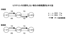
図13は、ヒステリシスを適用しない場合の経路選択を示す図である。ノード1とノード2との間では、2つの無線インターフェイスの通信コストが大きく異なるため、通信コストの小さい無線インターフェイス(802.11g)が常に選択される。一方、ノード2とノード3との間では、通信コストが等しいため、通信経路に用いる無線インターフェイスは確率的に選択される。そのため、新経路では旧経路と異なる無線インターフェイスが選択されることがあり、場合によっては通信経路を計算する毎に異なる無線インターフェイスが選択され、システムが不安定になる。
FIG. 13 is a diagram illustrating route selection when hysteresis is not applied. Since the communication costs of the two radio interfaces are greatly different between the
そのため、本発明の第7実施例では、図3のルーティング部において、ルーティングテーブルを参照して旧経路の無線インターフェイスが存在するか否かを確認する。旧経路で使用されていた無線インターフェイスが存在する場合には、旧経路で使用されていた無線インターフェイスに対する通信コストに1以下の重み付けを行う。このように重み付けされた通信コストを用いて無線インターフェイスの通信コストを比較することにより、複数の無線インターフェイスのうちから通信を行う無線インターフェイスを選択する。 Therefore, in the seventh embodiment of the present invention, the routing unit of FIG. 3 confirms whether or not the wireless interface of the old route exists with reference to the routing table. When there is a wireless interface used in the old route, the communication cost for the wireless interface used in the old route is weighted by 1 or less. By comparing the communication costs of the wireless interfaces using the weighted communication costs in this way, a wireless interface for communication is selected from the plurality of wireless interfaces.
図14に、本発明の第7実施例に従ってヒステリシスを適用した場合の経路選択を示す。第7実施例では、経路選択時にルーティングテーブルを参照し、旧経路で使用されていた無線インターフェイスの通信コストに1以下の重みを乗算する。図14では重みとして0.8を乗算している。このようにすることで、ノード2とノード3との間の旧経路で使用されていた無線インターフェイスが新経路においても選択されやすくなる。特に、2つのノード間の無線インターフェイスの通信コストが等しい場合又は通信コストの差が小さい場合には、旧経路が引き続き選択されやすくなり、システムが安定化する。
FIG. 14 shows route selection when hysteresis is applied according to the seventh embodiment of the present invention. In the seventh embodiment, the routing table is referred to when a route is selected, and the communication cost of the wireless interface used in the old route is multiplied by a weight of 1 or less. In FIG. 14, 0.8 is multiplied as a weight. By doing so, the wireless interface used in the old route between the
重みの値を小さくするほど、旧経路で使用されていた無線インターフェイスを選択する確率が高くなるため、重みの値を調整することにより、複数の無線インターフェイスによる負荷分散を図ることができ、システムの安定度との調整を図ることが可能になる。その結果、複数の無線インターフェイスを考慮した最適な経路選択が可能になる。 The smaller the weight value, the higher the probability that the radio interface used in the old route will be selected. By adjusting the weight value, load distribution by multiple radio interfaces can be achieved. It is possible to adjust the stability. As a result, optimal route selection considering a plurality of wireless interfaces becomes possible.
(フレーム構成例)
図15〜17を参照して、上記の実施例で使用されるリクエストフレーム及び経路確認フレームをIEEE802無線LANのフレーム構成に適用する例について説明する。
(Frame configuration example)
With reference to FIGS. 15 to 17, an example in which the request frame and the path confirmation frame used in the above-described embodiment are applied to the frame structure of the IEEE 802 wireless LAN will be described.
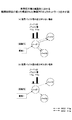
リクエストフレーム及び経路確認フレームを表す経路制御用のフレーム構成として、図15(a)に示すように、ヘッダの後にフレーム種別を表すControl IDを付与し、その後に経路制御用のペイロードを付与するフレーム構成を用いることができる。ヘッダ及びControl IDを用いて、リクエストフレーム又は経路確認フレームであることを表す。ペイロードには、上記の実施例で示した宛先アドレス、次ノードアドレス、送信インターフェイス、通信コスト値、リクエストID、設定時間等が設定される。なお、宛先アドレスのように、上記のペイロードの一部はヘッダに設定され、ペイロードに設定されなくてもよい。 As shown in FIG. 15 (a), as a frame structure for route control representing a request frame and a route confirmation frame, a frame to which a Control ID representing a frame type is attached after the header and a payload for route control is added thereafter. A configuration can be used. The header and the control ID are used to indicate a request frame or a route confirmation frame. In the payload, the destination address, the next node address, the transmission interface, the communication cost value, the request ID, the set time, and the like shown in the above embodiment are set. In addition, like the destination address, a part of the above payload is set in the header and may not be set in the payload.
IEEE802.11無線LANシステムで制御経路用のフレーム構成を用いる場合には、図15(b)に示すIEEE802.11 Action Frameを用いる場合と、図15(c)に示すIEEE802.2LLCを用いる場合とが考えられる。 When using the frame structure for the control path in the IEEE802.11 wireless LAN system, the case where the IEEE802.11 Action Frame shown in FIG. 15B is used, and the case where the IEEE802.2 LLC shown in FIG. 15C is used are used. Can be considered.
IEEE802.11 Action Frameを用いる場合、802.11ヘッダが図15(a)のヘッダに相当し、Category/Actionが図15(a)のControl IDに相当する。802.11ヘッダでは、Type及びSubtypeをType=00(management)及びSubtype=1101(action)に設定する。このように、802.11ヘッダを用いて制御経路用のフレームであることを特定することができる。次の802.11ペイロードの先頭で、Category及びActionを設定するときに、Categoryにメッシュネットワーク関連のアクションである識別子(mesh)を設定し、Actionにリクエストフレーム/経路確認フレームの種別を示す識別子を設定する。このように設定することにより、経路制御用ペイロードを特定することができる。 When IEEE802.11 Action Frame is used, the 802.11 header corresponds to the header of FIG. 15A, and Category / Action corresponds to the Control ID of FIG. In the 802.11 header, Type and Subtype are set to Type = 00 (management) and Subtype = 1101 (action). In this way, it is possible to identify the frame for the control path using the 802.11 header. When setting Category and Action at the beginning of the next 802.11 payload, set an identifier (mesh) that is an action related to the mesh network in Category, and set an identifier indicating the type of request frame / path confirmation frame in Action . By setting in this way, the path control payload can be specified.
IEEE802.2LLCを用いる場合、802.11ヘッダが図15(a)のヘッダに相当し、LLC/SNAPヘッダ及びIDが図15(a)のControl IDに相当する。802.11ヘッダでは、Type=dataになる。次のLLC/SNAPヘッダにはOUIと呼ばれる組織コードを示すフィールドが存在する。このOUIにメッシュネットワークを示す識別子(mesh)を設定し、その後のペイロードの区別を行う。また、OUI=meshである場合に次のペイロードの先頭にIDを設けて、リクエストフレーム/経路確認フレームの種別を示す識別子を設定する。このように設定することにより、経路制御用ペイロードを特定することができる。 When IEEE802.2LLC is used, the 802.11 header corresponds to the header of FIG. 15A, and the LLC / SNAP header and ID correspond to the Control ID of FIG. 15A. In the 802.11 header, Type = data. The next LLC / SNAP header includes a field indicating an organization code called OUI. An identifier (mesh) indicating a mesh network is set in this OUI, and subsequent payloads are distinguished. Further, when OUI = mesh, an ID is provided at the head of the next payload, and an identifier indicating the type of request frame / path confirmation frame is set. By setting in this way, the path control payload can be specified.
上記のいずれの構成を用いた場合においても、経路制御用ペイロードを特定することができるため、所定のフレーム構成に従って経路制御用ペイロードに情報を設定することができ、設定された情報を解読することができる。経路制御用ペイロードのフレーム構成例として、例えば図16及び図17の構成が含まれる。 In any of the above configurations, since the routing payload can be specified, information can be set in the routing payload according to a predetermined frame configuration, and the set information can be decoded. Can do. Examples of the frame configuration of the path control payload include the configurations of FIGS. 16 and 17.
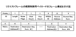
図16は、リクエストフレームの経路制御用ペイロードのフレーム構成を示す図である。上記のように、リクエストフレームには、送信元アドレス、宛先アドレス、リクエストフレーム固有のID及びリクエストフレーム送信元からの通信コストの値が含まれる。図16のRREQ IDがリクエストIDに対応し、Metricが通信コスト値に対応し、Source Addressが送信元アドレスに対応し、Destination Address#1が宛先アドレスに対応する。
FIG. 16 is a diagram illustrating a frame configuration of a request frame path control payload. As described above, the request frame includes a transmission source address, a destination address, an ID unique to the request frame, and a communication cost value from the request frame transmission source. 16 corresponds to the request ID, Metric corresponds to the communication cost value, Source Address corresponds to the transmission source address, and
図17は、図16に対応する経路確認フレームの経路制御用ペイロードのフレーム構成を示す図である。以上のように、図15〜17のフレーム構成を用いることにより、上記の実施例をIEEE802.11無線システムで実現することが可能になる。 FIG. 17 is a diagram showing a frame configuration of the path control payload of the path confirmation frame corresponding to FIG. As described above, by using the frame configurations of FIGS. 15 to 17, it is possible to implement the above-described embodiment in the IEEE 802.11 wireless system.
なお、本発明は、上記の実施例に限定されることなく、特許請求の範囲内において種々の変更及び応用が可能である。 In addition, this invention is not limited to said Example, A various change and application are possible within a claim.
10、20、30 無線通信装置
101、201、301 無線インターフェイス
103、203、303 無線インターフェイス
105、205、305 データ送受信部
107、207、307 ルーティング部
109、209、309 上位プロトコル部
121、221、321 通信経路制御装置
211、213 送信バッファ
215 測定部
317 所属端末管理部
10, 20, 30
Claims (13)
フレームを蓄積する複数の送信バッファを前記複数の無線インターフェイス毎に有し、
前記無線インターフェイス毎の前記複数の送信バッファに蓄積されたフレームの総データ量を前記複数の無線インターフェイス毎に測定する測定部と、
前記複数の無線インターフェイスのうちの1つでリクエストフレームを受信すると、各無線インターフェイス間の前記測定部で測定した総データ量測定値の差が閾値未満の場合に、前記複数の無線インターフェイスのうち少なくとも2つの無線インターフェイスから前記リクエストフレームを送信し、各無線インターフェイス間の前記測定部で測定した総データ量測定値の差のうち少なくとも1つの差が閾値以上の場合に、該総データ量の少ない方の無線インターフェイスから前記リクエストフレームを送信するデータ送受信部と、
前記リクエストフレームに基づいて、前記複数の無線インターフェイスのうちから通信を行う無線インターフェイスを選択するルーティング部と、
を有する無線通信装置。 A wireless communication device that communicates via a plurality of wireless interfaces in a wireless ad hoc network,
A plurality of transmission buffers for storing frames for each of the plurality of radio interfaces;
A measuring unit that measures the total data amount of the frames accumulated in the plurality of transmission buffers for each of the radio interfaces for each of the plurality of radio interfaces;
When a request frame is received by one of the plurality of wireless interfaces , if a difference in total data amount measurement value measured by the measurement unit between the wireless interfaces is less than a threshold value, at least one of the plurality of wireless interfaces When the request frame is transmitted from two radio interfaces and at least one of the differences in the total data measurement values measured by the measurement unit between the radio interfaces is greater than or equal to a threshold value, the smaller total data amount A data transmission / reception unit for transmitting the request frame from the wireless interface ;
Based on the request frame, a routing unit that selects a wireless interface for communication from the plurality of wireless interfaces;
A wireless communication device.
前記データ送受信部は、前記配下の端末からフレームを受信すると、該配下の端末に代わって前記リクエストフレームを送信することを特徴とする請求項1に記載の無線通信装置。 The wireless communication device functions as an access point that manages the terminals under its control,
The wireless communication apparatus according to claim 1, wherein the data transmitting / receiving unit transmits the request frame in place of the subordinate terminal when receiving the frame from the subordinate terminal.
前記データ送受信部は、前記無線通信装置の配下に新たな端末が所属したときに、該端末の所属を通知するフレームをブロードキャスト送信し、
前記所属端末管理部は、新たな端末の所属を通知するフレームを他の無線通信装置から受信すると、該端末の所属を前記所属端末情報から削除することを特徴とする請求項6に記載の無線通信装置。 It further has an affiliated terminal management unit that manages affiliated terminal information to which the subordinate terminal belongs,
The data transmitter / receiver, when a new terminal belongs to the wireless communication device, broadcasts a frame for notifying the belonging of the terminal,
The wireless terminal according to claim 6 , wherein the affiliated terminal management unit deletes the affiliated terminal information from the affiliated terminal information when receiving a frame notifying the membership of a new terminal from another wireless communication device. Communication device.
前記無線通信装置は、フレームを蓄積する複数の送信バッファを前記複数の無線インターフェイス毎に有し、
前記通信経路制御装置は、
前記無線インターフェイス毎の前記複数の送信バッファに蓄積されたフレームの総データ量を前記複数の無線インターフェイス毎に測定する手段と、
前記複数の無線インターフェイスのうちの1つでリクエストフレームを受信したことを検出すると、各無線インターフェイス間の測定した総データ量測定値の差が閾値未満の場合に、前記複数の無線インターフェイスのうち少なくとも2つの無線インターフェイスから前記リクエストフレームを送信し、各無線インターフェイス間の測定した総データ量測定値の差のうち少なくとも1つの差が閾値以上の場合に、該総データ量の少ない方の無線インターフェイスから前記リクエストフレームを送信する手段と、
前記リクエストフレームに基づいて、前記複数の無線インターフェイスのうちから通信を行う無線インターフェイスを選択する手段と
を有する通信経路制御装置。 A communication path control device for a wireless communication device that communicates via a plurality of wireless interfaces in a wireless ad hoc network,
The wireless communication device has a plurality of transmission buffers for storing frames for each of the plurality of wireless interfaces,
The communication path control device includes:
Means for measuring, for each of the plurality of radio interfaces, a total data amount of frames accumulated in the plurality of transmission buffers for each of the radio interfaces;
When detecting that a request frame has been received by one of the plurality of wireless interfaces , if a difference in measured total data amount between the wireless interfaces is less than a threshold value, at least one of the plurality of wireless interfaces When the request frame is transmitted from two wireless interfaces, and at least one difference among the measured data amount differences between the wireless interfaces is equal to or greater than a threshold value, the wireless interface with the smaller total data amount Means for transmitting the request frame ;
A communication path control device comprising: means for selecting a wireless interface for performing communication among the plurality of wireless interfaces based on the request frame.
送信元ノードが、リクエストフレームを送信するステップと、
前記複数の無線通信装置のそれぞれが、前記複数の無線インターフェイスのうちの1つで前記リクエストフレームを受信するステップと、
前記複数の無線通信装置のそれぞれが、前記リクエストフレームに基づいて、前記複数の無線インターフェイスのうちから通信を行う無線インターフェイスを選択するステップと、
送信バッファに蓄積されたフレームの総データ量を前記複数の無線インターフェイス毎に測定するステップと、
前記複数の無線通信装置のそれぞれが、各無線インターフェイス間の測定した総データ量測定値の差が閾値未満の場合に、前記複数の無線インターフェイスのうち少なくとも2つの無線インターフェイスから前記リクエストフレームを送信し、各無線インターフェイス間の測定した総データ量測定値の差のうち少なくとも1つの差が閾値以上の場合に、該総データ量の少ない方の無線インターフェイスから前記リクエストフレームを送信するステップと、
宛先ノードが、前記リクエストフレームを受信すると、前記リクエストフレームの応答信号を返信するステップと、
前記複数の無線通信装置のそれぞれが、前記リクエストフレームの応答信号を受信すると、該応答信号に基づいて、通信経路を確立するステップと、
を有する通信経路制御方法。 A communication path control method in a wireless ad hoc network including a plurality of wireless communication devices each having a plurality of wireless interfaces,
A source node sending a request frame;
Each of the plurality of wireless communication devices receiving the request frame on one of the plurality of wireless interfaces;
Each of the plurality of wireless communication devices, based on the request frame, selecting a wireless interface for communication from the plurality of wireless interfaces;
Measuring a total data amount of frames accumulated in a transmission buffer for each of the plurality of radio interfaces;
Each of the plurality of wireless communication devices, if the difference between the measured total data amount measurement values among the wireless interfaces is less than the threshold value, it transmits the request frame from at least two wireless interfaces of the plurality of wireless interfaces Transmitting the request frame from the wireless interface with the smaller total data amount when at least one of the measured total data amount measurement differences between the wireless interfaces is greater than or equal to a threshold value ;
When the destination node receives the request frame, it returns a response signal of the request frame;
When each of the plurality of wireless communication devices receives a response signal of the request frame, establishing a communication path based on the response signal;
A communication path control method comprising:
前記複数の無線通信装置のそれぞれが、
フレームを蓄積する複数の送信バッファを前記複数の無線インターフェイス毎に有し、
前記無線インターフェイス毎の前記複数の送信バッファに蓄積されたフレームの総データ量を前記複数の無線インターフェイス毎に測定する測定部と、
前記複数の無線インターフェイスのうちの1つでリクエストフレームを受信すると、各無線インターフェイス間の前記測定部で測定した総データ量測定値の差が閾値未満の場合に、前記複数の無線インターフェイスのうち少なくとも2つの無線インターフェイスから前記リクエストフレームを送信し、各無線インターフェイス間の前記測定部で測定した総データ量測定値の差のうち少なくとも1つの差が閾値以上の場合に、該総データ量の少ない方の無線インターフェイスから前記リクエストフレームを送信するデータ送受信部と、
前記リクエストフレームに基づいて、前記複数の無線インターフェイスのうちから通信を行う無線インターフェイスを選択するルーティング部と、
を有することを特徴とする通信システム。 A communication system for a wireless ad hoc network including a plurality of wireless communication devices each having a plurality of wireless interfaces,
Each of the plurality of wireless communication devices is
A plurality of transmission buffers for storing frames for each of the plurality of radio interfaces;
A measuring unit that measures the total data amount of the frames accumulated in the plurality of transmission buffers for each of the radio interfaces for each of the plurality of radio interfaces;
Receive one requests frames of the plurality of wireless interfaces Then, if the difference between the total data amount measurement value measured by the measuring portion between the radio interface is less than the threshold value, among the plurality of wireless interfaces When the request frame is transmitted from at least two radio interfaces and at least one of the differences in the total data measurement values measured by the measurement unit between the radio interfaces is greater than or equal to a threshold value, the total data amount is small. A data transmitter / receiver for transmitting the request frame from the other wireless interface;
Based on the request frame, a routing unit that selects a wireless interface for communication from the plurality of wireless interfaces;
Communication system, comprising a.
Priority Applications (6)
| Application Number | Priority Date | Filing Date | Title |
|---|---|---|---|
| JP2006019461A JP4762735B2 (en) | 2005-02-16 | 2006-01-27 | Wireless communication apparatus, communication path control apparatus, communication path control method, and communication system |
| US11/816,332 US7948891B2 (en) | 2005-02-16 | 2006-02-15 | Wireless communication apparatus, communication routing control apparatus, communication routing control method and communication system |
| EP20060713811 EP1850538B1 (en) | 2005-02-16 | 2006-02-15 | Radio communication device, communication route control device, communication route control method, and communication system |
| CN200680004969XA CN101120555B (en) | 2005-02-16 | 2006-02-15 | Radio communication device, communication route control device, communication route control method, and communication system |
| PCT/JP2006/302670 WO2006088066A1 (en) | 2005-02-16 | 2006-02-15 | Radio communication device, communication route control device, communication route control method, and communication system |
| KR20077018588A KR100900307B1 (en) | 2005-02-16 | 2006-02-15 | Radio Communication Device, Communication Route Control Device, Communication Route Control Method, and Communication System |
Applications Claiming Priority (5)
| Application Number | Priority Date | Filing Date | Title |
|---|---|---|---|
| JP2005039173 | 2005-02-16 | ||
| JP2005039173 | 2005-02-16 | ||
| JP2005098577 | 2005-03-30 | ||
| JP2005098577 | 2005-03-30 | ||
| JP2006019461A JP4762735B2 (en) | 2005-02-16 | 2006-01-27 | Wireless communication apparatus, communication path control apparatus, communication path control method, and communication system |
Publications (2)
| Publication Number | Publication Date |
|---|---|
| JP2006311495A JP2006311495A (en) | 2006-11-09 |
| JP4762735B2 true JP4762735B2 (en) | 2011-08-31 |
Family
ID=36916470
Family Applications (1)
| Application Number | Title | Priority Date | Filing Date |
|---|---|---|---|
| JP2006019461A Expired - Fee Related JP4762735B2 (en) | 2005-02-16 | 2006-01-27 | Wireless communication apparatus, communication path control apparatus, communication path control method, and communication system |
Country Status (6)
| Country | Link |
|---|---|
| US (1) | US7948891B2 (en) |
| EP (1) | EP1850538B1 (en) |
| JP (1) | JP4762735B2 (en) |
| KR (1) | KR100900307B1 (en) |
| CN (1) | CN101120555B (en) |
| WO (1) | WO2006088066A1 (en) |
Families Citing this family (29)
| Publication number | Priority date | Publication date | Assignee | Title |
|---|---|---|---|---|
| US8340106B2 (en) | 2006-03-13 | 2012-12-25 | Microsoft Corporation | Connecting multi-hop mesh networks using MAC bridge |
| JP2008061227A (en) * | 2006-08-02 | 2008-03-13 | Advanced Telecommunication Research Institute International | Wireless device, wireless communication network including the same, and channel detection method in wireless device |
| KR101307803B1 (en) * | 2006-12-13 | 2013-09-12 | 삼성전자주식회사 | Network traffic distributed method and network system using the same |
| JP4863863B2 (en) * | 2006-12-22 | 2012-01-25 | 三菱電機株式会社 | Repeater, communication network system |
| CN101669326B (en) | 2007-02-27 | 2014-11-12 | 安移通网络公司 | Method and system for radio frequency management in a mesh network with a path distance factor |
| JP2009033730A (en) * | 2007-06-26 | 2009-02-12 | Ricoh Co Ltd | Wireless communication apparatus, wireless communication method, and wireless communication program |
| US8913590B2 (en) * | 2007-12-28 | 2014-12-16 | Telecom Italia S.P.A. | Management of a hybrid communication network comprising a cellular network and a local network |
| JP5066455B2 (en) * | 2008-01-28 | 2012-11-07 | Kddi株式会社 | Wireless communication path determination device and wireless communication path determination method |
| JP2010050903A (en) * | 2008-08-25 | 2010-03-04 | Fujitsu Ltd | Transmission apparatus |
| JP5711446B2 (en) * | 2009-01-13 | 2015-04-30 | 株式会社ナカヨ | Wireless terminal device |
| FR2942925A1 (en) * | 2009-03-03 | 2010-09-10 | Thomson Licensing | METHOD OF CALIBRATION OF MULTISECTORAL ANTENNA TERMINAL AND TERMINAL OF A MESH NETWORK |
| GB2473849B (en) * | 2009-09-25 | 2015-06-17 | Ge Aviat Systems Ltd | Module communication |
| JP5514520B2 (en) * | 2009-11-25 | 2014-06-04 | 株式会社メガチップス | Communication system and communication apparatus |
| JP5255579B2 (en) * | 2010-02-09 | 2013-08-07 | 日立オートモティブシステムズ株式会社 | In-car data relay device, vehicle control system |
| JP5438614B2 (en) * | 2010-07-15 | 2014-03-12 | 大阪瓦斯株式会社 | Network reconstruction method and network system |
| JP5662859B2 (en) * | 2011-03-29 | 2015-02-04 | Kddi株式会社 | Path setting method considering the effect of data compression in the network |
| JP5750973B2 (en) * | 2011-03-29 | 2015-07-22 | 富士通株式会社 | Communication method and communication apparatus |
| US9106567B2 (en) * | 2011-12-21 | 2015-08-11 | Silver Spring Networks, Inc. | System and method for setting a path to an access point across a wireless mesh network |
| US10642897B2 (en) * | 2012-03-23 | 2020-05-05 | Sap Se | Distance in contextual network graph |
| ES2541527T3 (en) * | 2012-08-06 | 2015-07-21 | Itron, Inc. | Multiple multimedia modulation and mesh network with multiple data rates |
| FR3005546B1 (en) * | 2013-05-13 | 2015-05-29 | Commissariat Energie Atomique | METHOD AND DEVICE FOR SELECTING COMMUNICATION INTERFACE |
| JP6259622B2 (en) * | 2013-09-26 | 2018-01-10 | 関西電力株式会社 | COMMUNICATION DEVICE, RADIO NETWORK SYSTEM, RADIO NETWORK CONTROL METHOD, AND RADIO NETWORK CONTROL PROGRAM |
| US10015720B2 (en) | 2014-03-14 | 2018-07-03 | GoTenna, Inc. | System and method for digital communication between computing devices |
| JP5809727B2 (en) * | 2014-03-25 | 2015-11-11 | 日本電信電話株式会社 | Wireless network construction device, wireless network system, and wireless network construction method |
| CN103957162B (en) * | 2014-05-14 | 2017-02-15 | 常熟理工学院 | Routing communication realization method of wireless network |
| US10666394B2 (en) * | 2015-04-27 | 2020-05-26 | Sony Corporation | Information processing device, communication system, information processing method, and program |
| US20170245195A1 (en) * | 2016-02-22 | 2017-08-24 | Mediatek Inc. | Method for controlling network interfaces of electronic device and associated processing circuit |
| US11245633B2 (en) * | 2016-08-18 | 2022-02-08 | Telefonaktiebolaget Lm Ericsson (Publ) | Method and wireless device for handling transmission of data |
| JP6913957B2 (en) * | 2019-03-29 | 2021-08-04 | 国立研究開発法人情報通信研究機構 | Wireless communication system and wireless communication method |
Family Cites Families (11)
| Publication number | Priority date | Publication date | Assignee | Title |
|---|---|---|---|---|
| JP2947351B1 (en) | 1998-08-26 | 1999-09-13 | 日本電信電話株式会社 | Learning type wireless packet transfer method and wireless base station using the method |
| JP3010157B1 (en) | 1998-08-28 | 2000-02-14 | 日本電信電話株式会社 | Wireless packet transfer method and wireless base station using the method |
| US6757270B1 (en) * | 1999-06-11 | 2004-06-29 | Lucent Technologies Inc. | Low back haul reactivation delay for high-speed packet data services in CDMA systems |
| US6625164B1 (en) * | 1999-07-14 | 2003-09-23 | Qualcomm, Incorporated | Selectively framing and unframing PPP packets depending on negotiated options on the Um and Rm interfaces |
| JP3869712B2 (en) | 2001-12-14 | 2007-01-17 | 株式会社日立国際電気 | Wireless bridge |
| JP3779673B2 (en) * | 2002-10-30 | 2006-05-31 | 株式会社東芝 | Relay device and communication system |
| DE60335867D1 (en) * | 2003-07-10 | 2011-03-10 | Alcatel Lucent | Reduction of bandwidth and power consumption in a multimode mobile terminal by selectively monitoring multiple radio interfaces |
| GB0317372D0 (en) * | 2003-07-25 | 2003-08-27 | Royal Holloway University Of L | Routing protocol for ad hoc networks |
| US7480248B2 (en) * | 2003-08-22 | 2009-01-20 | Samsung Electronics Co., Ltd. | Apparatus and method for determining aggregated link costs in a mobile ad hoc network |
| KR100605896B1 (en) * | 2003-10-07 | 2006-08-01 | 삼성전자주식회사 | Method for establishing route route using partial route discovery in mobile ad hoc network and mobile terminal |
| US7414977B2 (en) * | 2003-11-25 | 2008-08-19 | Mitsubishi Electric Research Laboratories, Inc. | Power and delay sensitive ad-hoc communication networks |
-
2006
- 2006-01-27 JP JP2006019461A patent/JP4762735B2/en not_active Expired - Fee Related
- 2006-02-15 US US11/816,332 patent/US7948891B2/en not_active Expired - Fee Related
- 2006-02-15 WO PCT/JP2006/302670 patent/WO2006088066A1/en not_active Ceased
- 2006-02-15 EP EP20060713811 patent/EP1850538B1/en not_active Expired - Lifetime
- 2006-02-15 CN CN200680004969XA patent/CN101120555B/en not_active Expired - Fee Related
- 2006-02-15 KR KR20077018588A patent/KR100900307B1/en not_active Expired - Fee Related
Also Published As
| Publication number | Publication date |
|---|---|
| KR100900307B1 (en) | 2009-06-02 |
| JP2006311495A (en) | 2006-11-09 |
| EP1850538A4 (en) | 2010-08-04 |
| US7948891B2 (en) | 2011-05-24 |
| WO2006088066A1 (en) | 2006-08-24 |
| EP1850538A1 (en) | 2007-10-31 |
| CN101120555B (en) | 2011-12-14 |
| EP1850538B1 (en) | 2012-02-15 |
| US20090052374A1 (en) | 2009-02-26 |
| CN101120555A (en) | 2008-02-06 |
| KR20070097573A (en) | 2007-10-04 |
Similar Documents
| Publication | Publication Date | Title |
|---|---|---|
| JP4762735B2 (en) | Wireless communication apparatus, communication path control apparatus, communication path control method, and communication system | |
| EP1966961B1 (en) | Method and system for improving a wireless communication route | |
| CN1860748B (en) | Wireless communication device and route search method | |
| JP4425863B2 (en) | Packet transfer system and radio base station | |
| US7346015B2 (en) | Method and apparatus for routing data with support for changing mobility requirements | |
| US5987011A (en) | Routing method for Ad-Hoc mobile networks | |
| US8392607B2 (en) | Relay device, control method, and program | |
| JP4679616B2 (en) | Wireless LAN relay device, wireless LAN relay method, and computer program | |
| US8213352B2 (en) | Wireless communication system, wireless communication device, wireless communication method, and program | |
| US7359358B2 (en) | Method and apparatus for routing data | |
| JP2007129542A (en) | Wireless communication system, wireless communication apparatus, wireless communication method, and computer program | |
| JP5720793B2 (en) | Data transfer method and node apparatus using the same | |
| Liu et al. | Distributed contention-aware call admission control for IEEE 802.11 multi-radio multi-rate multi-channel wireless mesh networks | |
| JPWO2008038390A1 (en) | Mobile IP communication system | |
| JP2007201781A (en) | Wireless packet communication system and wireless packet communication method | |
| JP5119603B2 (en) | Wireless terminal device and program |
Legal Events
| Date | Code | Title | Description |
|---|---|---|---|
| A621 | Written request for application examination |
Free format text: JAPANESE INTERMEDIATE CODE: A621 Effective date: 20081113 |
|
| A131 | Notification of reasons for refusal |
Free format text: JAPANESE INTERMEDIATE CODE: A131 Effective date: 20110118 |
|
| A521 | Request for written amendment filed |
Free format text: JAPANESE INTERMEDIATE CODE: A523 Effective date: 20110322 |
|
| TRDD | Decision of grant or rejection written | ||
| A01 | Written decision to grant a patent or to grant a registration (utility model) |
Free format text: JAPANESE INTERMEDIATE CODE: A01 Effective date: 20110607 |
|
| A01 | Written decision to grant a patent or to grant a registration (utility model) |
Free format text: JAPANESE INTERMEDIATE CODE: A01 |
|
| A61 | First payment of annual fees (during grant procedure) |
Free format text: JAPANESE INTERMEDIATE CODE: A61 Effective date: 20110608 |
|
| FPAY | Renewal fee payment (event date is renewal date of database) |
Free format text: PAYMENT UNTIL: 20140617 Year of fee payment: 3 |
|
| R150 | Certificate of patent or registration of utility model |
Ref document number: 4762735 Country of ref document: JP Free format text: JAPANESE INTERMEDIATE CODE: R150 Free format text: JAPANESE INTERMEDIATE CODE: R150 |
|
| R250 | Receipt of annual fees |
Free format text: JAPANESE INTERMEDIATE CODE: R250 |
|
| R250 | Receipt of annual fees |
Free format text: JAPANESE INTERMEDIATE CODE: R250 |
|
| R250 | Receipt of annual fees |
Free format text: JAPANESE INTERMEDIATE CODE: R250 |
|
| R250 | Receipt of annual fees |
Free format text: JAPANESE INTERMEDIATE CODE: R250 |
|
| R250 | Receipt of annual fees |
Free format text: JAPANESE INTERMEDIATE CODE: R250 |
|
| LAPS | Cancellation because of no payment of annual fees |