JP4707640B2 - Contact device - Google Patents
Contact device Download PDFInfo
- Publication number
- JP4707640B2 JP4707640B2 JP2006273868A JP2006273868A JP4707640B2 JP 4707640 B2 JP4707640 B2 JP 4707640B2 JP 2006273868 A JP2006273868 A JP 2006273868A JP 2006273868 A JP2006273868 A JP 2006273868A JP 4707640 B2 JP4707640 B2 JP 4707640B2
- Authority
- JP
- Japan
- Prior art keywords
- case
- housing
- extending
- axial direction
- contact device
- Prior art date
- Legal status (The legal status is an assumption and is not a legal conclusion. Google has not performed a legal analysis and makes no representation as to the accuracy of the status listed.)
- Active
Links
- 210000000078 claw Anatomy 0.000 claims description 39
- 239000011521 glass Substances 0.000 description 3
- 239000011347 resin Substances 0.000 description 3
- 229920005989 resin Polymers 0.000 description 3
- 230000037431 insertion Effects 0.000 description 2
- 238000003780 insertion Methods 0.000 description 2
- 239000002184 metal Substances 0.000 description 2
- 239000005357 flat glass Substances 0.000 description 1
Images

Landscapes
- Connection Of Plates (AREA)
- Details Of Connecting Devices For Male And Female Coupling (AREA)
Description
本発明は、接点装置に関する。 The present invention relates to a contact device.
特開2005−166312号公報は、ハウジングがケースから外れる(脱落する)ことを防止するために、ケースにケース側爪が設けられハウジングにハウジング側爪が設けられている接点装置を開示している。ケース側爪は、ケースから接点装置の軸方向と直交する方向に直線状に延びている。ハウジング側爪は、ハウジングから接点装置の軸方向と直交する方向に直線状に延びている。 Japanese Patent Laying-Open No. 2005-166212 discloses a contact device in which a case side claw is provided on the case and a housing side claw is provided on the housing in order to prevent the housing from being removed (dropped off) from the case. . The case side claw extends linearly from the case in a direction orthogonal to the axial direction of the contact device. The housing side claw extends linearly from the housing in a direction orthogonal to the axial direction of the contact device.
しかし、従来の接点装置にはつぎの問題点がある。
ケース側爪とハウジング側爪が接点装置の軸方向と直交する方向に直線状に延びているため、接点装置を該接点装置が取付けられる部材に取り付けるとき等に、ハウジングに工具などが当りハウジングに接点装置の軸方向と直交する方向の荷重が加わる可能性がある。その荷重によってハウジングが弾性変形してケースから外れてしまうおそれがある。
Since the case side claw and the housing side claw extend linearly in a direction perpendicular to the axial direction of the contact device, when the contact device is attached to a member to which the contact device is attached, the tool hits the housing and hits the housing. There is a possibility that a load in a direction orthogonal to the axial direction of the contact device is applied. The load may cause the housing to elastically deform and come off the case.
本発明の目的は、ハウジングがケースから外れてしまうことを従来に比べて防止できる接点装置を提供することにある。 The objective of this invention is providing the contact apparatus which can prevent that a housing remove | deviates from a case compared with the past.
上記目的を達成する本発明はつぎの通りである。
(1) ケースと、
前記ケースに対して接点装置の軸方向に可動なハウジングと、
前記ケースに設けられるケース側爪と、
前記ハウジングに設けられ前記ケース側爪と係合可能なハウジング側爪と、
を有し、
前記ケース側爪は、前記ケースから前記接点装置の軸方向と直交または略直交する方向に延びる第1の延び部と、該第1の延び部の延び方向先端部から前記接点装置の軸方向と平行または略平行な方向に延びる第2の延び部と、を備えており、
前記ハウジング側爪は、前記ハウジングから前記接点装置の軸方向と直交または略直交する方向に延びる第3の延び部と、該第3の延び部の延び方向先端部から前記接点装置の軸方向と平行または略平行な方向に延びる第4の延び部と、を備えている、接点装置。
The present invention for achieving the above object is as follows.
(1) Case and
A housing movable in the axial direction of the contact device with respect to the case;
A case side claw provided in the case;
A housing side claw provided in the housing and engageable with the case side claw;
Have
The case-side claw includes a first extending portion extending from the case in a direction orthogonal or substantially orthogonal to the axial direction of the contact device, and an extending direction tip of the first extending portion from an axial direction of the contact device. A second extension portion extending in a parallel or substantially parallel direction,
The housing side pawl has a third extending portion extending from the housing in a direction orthogonal or substantially orthogonal to the axial direction of the contact device, and an extending direction tip of the third extending portion from the axial direction of the contact device. And a fourth extension extending in a parallel or substantially parallel direction.
上記(1)の接点装置によれば、ケース側爪が、ケースから接点装置の軸方向と直交または略直交する方向に延びる第1の延び部と、第1の延び部の延び方向先端部から接点装置の軸方向と平行または略平行な方向に延びる第2の延び部と、を備えており、ハウジング側爪が、ハウジングから接点装置の軸方向と直交または略直交する方向に延びる第3の延び部と、第3の延び部の延び方向先端部から接点装置の軸方向と平行または略平行な方向に延びる第4の延び部と、を備えているため、ハウジングに接点装置の軸方向と直交する方向の荷重がかかったときに、ケース側爪の第2の延び部とハウジング側爪の第4の延び部とを係合させることができる。その結果、ハウジングに接点装置の軸方向と直交する方向の荷重がかかっても、ケース側爪に第2の延び部が設けられておらずハウジングに第4の延び部が設けられていない場合(従来)に比べて、ハウジングがケースから外れてしまうことを防止できる。 According to the contact device of the above (1), the case side claw is formed from the first extending portion extending from the case in a direction orthogonal or substantially orthogonal to the axial direction of the contact device, and the extending direction front end portion of the first extending portion. A second extension portion extending in a direction parallel or substantially parallel to the axial direction of the contact device, and a housing side claw extending from the housing in a direction orthogonal or substantially orthogonal to the axial direction of the contact device. An extension portion, and a fourth extension portion extending in a direction parallel to or substantially parallel to the axial direction of the contact device from the distal end portion in the extension direction of the third extension portion. When a load in an orthogonal direction is applied, the second extending portion of the case side claw and the fourth extending portion of the housing side claw can be engaged. As a result, even when a load in a direction orthogonal to the axial direction of the contact device is applied to the housing, the case side claw is not provided with the second extension, and the housing is not provided with the fourth extension ( Compared to the conventional case, the housing can be prevented from coming off the case.
図1、図2は、本発明実施例の接点装置を示している。
本発明実施例の接点装置10は、例えば、車両のウィンドウガラスに設けられる図示略のガラスアンテナに接触させて用いられる。
1 and 2 show a contact device according to an embodiment of the present invention.
The
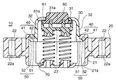
接点装置10は、図1に示すように、ケース20と、ケース20に対して接点装置10の軸方向(図1の上下方向であり、以下、軸方向という)に可動なハウジング30と、ケース20に設けられるケース側爪40と、ハウジング30に設けられケース側爪40と係合可能なハウジング側爪50と、を有する。接点装置10は、さらに、接点部60と、付勢部材70と、を有する。
As shown in FIG. 1, the
ケース20は、たとえば樹脂製である。ケース20は、内壁面がハウジング30を軸方向にガイドするガイド面21aとされているケース本体21と、ケース本体21の外壁面の外側に位置し挿入用穴22aが設けられる取付け部22と、付勢部材70の座を構成する座部23と、を備える。
取付け部22の挿入用穴22aには、ケース20を該ケース20が取付けられる図示略の相手部材(筐体)に取付けるためのビス、ボルト等が挿入される。
Screws, bolts, and the like for attaching the
ハウジング30は、たとえば樹脂製である。ハウジング30は、ケース本体21のガイド面21aに沿って、ケース20に対して軸方向に可動である。ハウジング30は、図2に示すように、平板壁31と、互いに対向する2つの側壁32と、を備える。
平板壁31には、接点部60の一部をハウジング30から外に露出させる貫通孔31aが設けられている。
側壁32は、軸方向と直交する方向の力がかかったとき、樹脂弾性を利用して互いに接近・離反する方向に弾性変形可能である。
The
The
When a force in a direction orthogonal to the axial direction is applied, the
ケース側爪40は、図1に示すように、ケース本体21の軸方向の一端部(図1の上端部)に設けられる。ケース側爪40は、ケース本体21から軸方向と直交または略直交する方向にハウジング30の側壁32側に延びる第1の延び部41と、第1の延び部41の延び方向先端部から軸方向と平行または略平行な方向にケース本体21の軸方向の他端側(図1の下側)に延びる第2の延び部42と、を備える。第1の延び部41と第2の延び部42は直線状に延びていてもよく、少なくとも一部に湾曲部を有して延びていてもよい。第2の延び部42の延び方向先端部は、ハウジング30の側壁32とハウジング側爪50の第4の延び部52との間に入り込んでいる。
As shown in FIG. 1, the
ケース側爪40が第1、第2の延び部41,42を備えるため、ケース本体21とケース側爪40とは、断面視で英語の「J」を上下方向に反転させた形状、または、断面視で英語の「J」を上下方向および左右方向に反転させた形状と同じかまたはほぼ同じ形状になる。
Since the
ハウジング側爪50は、ハウジング30の側壁32の、平板壁31と反対側の端部(図1の下端部、自由端部)に設けられる。ハウジング側爪50は、側壁32から軸方向と直交または略直交する方向にケース本体21側に延びる第3の延び部51と、第3の延び部51の延び方向先端部から軸方向と平行または略平行な方向に平板壁31側(図1の上側)に延びる第4の延び部52と、を備える。第3の延び部51と第4の延び部52は直線状に延びていてもよく、少なくとも一部に湾曲部を有して延びていてもよい。第4の延び部52の延び方向先端部は、ケース20のケース本体21とケース側爪40の第2の延び部42との間に入り込んでいる。
The housing-
ハウジング側爪50が第3、第4の延び部51,52を備えるため、側壁32とハウジング側爪50とは、断面視で英語の「J」または断面視で英語の「J」を左右方向に反転させた形状と同じかまたはほぼ同じ形状になる。
Since the housing-
接点部60は、導電性ゴムからなる。接点部60は、図示略のガラスアンテナに接触する。接点部60は、フランジ部61を備えている。接点部60は、フランジ部61が圧入される金属プレート61aの抱え込み部分が貫通孔31aの周囲の平板壁31に当接することにより、ハウジング30から外れないように(抜けないように)されている。ただし、接点部60は、金属プレート61aが設けられない場合には、フランジ部61が貫通孔31aの周囲の平板壁31に直接当接することにより、ハウジング30から外れないように(抜けないように)されていてもよい。
The
付勢部材70は、接点部60を図示略のガラスアンテナに押し付ける方向に(軸方向でケース側爪40とハウジング側爪50とが係合し合う方向に)、接点部60とハウジング30とハウジング側爪50をケース20に対して付勢する部材である。付勢部材70は、たとえばコイルスプリングからなる。ただし、付勢部材70はコイルスプリング以外からなっていてもよい。付勢部材70は、1部品のみ設けられていてもよく、2部品以上設けられていてもよい。
The
つぎに、本発明実施例の作用を説明する。
本発明実施例では、ケース側爪40が、ケース20から軸方向と直交または略直交する方向に延びる第1の延び部41と、第1の延び部41の延び方向先端部から軸方向と平行または略平行な方向に延びる第2の延び部42と、を備えており、ハウジング側爪50が、ハウジング30から軸方向と直交または略直交する方向に延びる第3の延び部51と、第3の延び部51の延び方向先端部から軸方向と平行または略平行な方向に延びる第4の延び部52と、を備えているため、ハウジング30に軸方向と直交する方向の荷重がかかったときに、ケース側爪40の第2の延び部42とハウジング側爪50の第4の延び部52とが係合する(引っ掛かる、当接する)。その結果、ハウジング30に軸方向と直交する方向の荷重がかかっても、ケース側爪40に第2の延び部42が設けられておらずハウジング50に第4の延び部52が設けられていない場合(従来)に比べて、ハウジング30がケース20から外れてしまうことを防止できる。
Next, the operation of the embodiment of the present invention will be described.
In the embodiment of the present invention, the
10 接点装置
20 ケース
21 ケース本体
22 取付け部
23 座部
30 ハウジング
31 平板壁
32 側壁
40 ケース側爪
41 第1の延び部
42 第2の延び部
50 ハウジング側爪
51 第3の延び部
52 第4の延び部
60 接点部
61 接点部のフランジ部
70 付勢部材
DESCRIPTION OF
Claims (1)
前記ケースに対して接点装置の軸方向に可動なハウジングと、
前記ケースに設けられるケース側爪と、
前記ハウジングに設けられ前記ケース側爪と係合可能なハウジング側爪と、
を有し、
前記ケース側爪は、前記ケースから前記接点装置の軸方向と直交または略直交する方向に延びる第1の延び部と、該第1の延び部の延び方向先端部から前記接点装置の軸方向と平行または略平行な方向に延びる第2の延び部と、を備えており、
前記ハウジング側爪は、前記ハウジングから前記接点装置の軸方向と直交または略直交する方向に延びる第3の延び部と、該第3の延び部の延び方向先端部から前記接点装置の軸方向と平行または略平行な方向に延びる第4の延び部と、を備えている、接点装置。 Case and
A housing movable in the axial direction of the contact device with respect to the case;
A case side claw provided in the case;
A housing side claw provided in the housing and engageable with the case side claw;
Have
The case-side claw includes a first extending portion extending from the case in a direction orthogonal or substantially orthogonal to the axial direction of the contact device, and an extending direction tip of the first extending portion from an axial direction of the contact device. A second extension portion extending in a parallel or substantially parallel direction,
The housing side pawl has a third extending portion extending from the housing in a direction orthogonal or substantially orthogonal to the axial direction of the contact device, and an extending direction tip of the third extending portion from the axial direction of the contact device. And a fourth extension extending in a parallel or substantially parallel direction.
Priority Applications (1)
| Application Number | Priority Date | Filing Date | Title |
|---|---|---|---|
| JP2006273868A JP4707640B2 (en) | 2006-10-05 | 2006-10-05 | Contact device |
Applications Claiming Priority (1)
| Application Number | Priority Date | Filing Date | Title |
|---|---|---|---|
| JP2006273868A JP4707640B2 (en) | 2006-10-05 | 2006-10-05 | Contact device |
Publications (2)
| Publication Number | Publication Date |
|---|---|
| JP2008091297A JP2008091297A (en) | 2008-04-17 |
| JP4707640B2 true JP4707640B2 (en) | 2011-06-22 |
Family
ID=39375227
Family Applications (1)
| Application Number | Title | Priority Date | Filing Date |
|---|---|---|---|
| JP2006273868A Active JP4707640B2 (en) | 2006-10-05 | 2006-10-05 | Contact device |
Country Status (1)
| Country | Link |
|---|---|
| JP (1) | JP4707640B2 (en) |
Families Citing this family (1)
| Publication number | Priority date | Publication date | Assignee | Title |
|---|---|---|---|---|
| CN111653887B (en) * | 2020-05-11 | 2025-10-03 | 苏茂均 | socket |
Family Cites Families (2)
| Publication number | Priority date | Publication date | Assignee | Title |
|---|---|---|---|---|
| JP2000268903A (en) * | 1999-03-16 | 2000-09-29 | Tyco Electronics Amp Kk | Circuit substrate connector |
| JP4194924B2 (en) * | 2003-11-28 | 2008-12-10 | 小島プレス工業株式会社 | Contact device |
-
2006
- 2006-10-05 JP JP2006273868A patent/JP4707640B2/en active Active
Also Published As
| Publication number | Publication date |
|---|---|
| JP2008091297A (en) | 2008-04-17 |
Similar Documents
| Publication | Publication Date | Title |
|---|---|---|
| KR20140072911A (en) | Joint connector | |
| US20140311038A1 (en) | Hole Plug | |
| TWI547021B (en) | Electrical connector | |
| JP2001023715A (en) | Terminal metal fitting | |
| JP5947485B2 (en) | Relay connector | |
| WO2017203935A1 (en) | Rotary connector and fixing structure of rotary connector | |
| JP4707640B2 (en) | Contact device | |
| TWI532265B (en) | Connection terminal and connector using the same | |
| US10153578B2 (en) | Connector structure | |
| JP2010049844A (en) | Connector and terminal metal fitting | |
| US20100319792A1 (en) | Flush control valve core assembly | |
| JP6088345B2 (en) | connector | |
| JP6131913B2 (en) | Wire harness fixing device and harness module | |
| JP2000039016A (en) | Control cable terminal fixing device | |
| JP5738482B2 (en) | Direct plug element especially for vehicle control equipment | |
| JP5626106B2 (en) | Electronic device housing structure | |
| JP2013236183A (en) | Antenna mounting washer and antenna device for vehicle, and antenna fixing method | |
| JP2007066614A (en) | Connector for substrate | |
| JP5676302B2 (en) | Drawer connector | |
| JP4835981B2 (en) | Image forming apparatus | |
| JP6258841B2 (en) | Terminal fitting jig and terminal insertion method | |
| JP4895950B2 (en) | Mounting structure of resin member for vehicle and resin clamp | |
| CN111164387A (en) | Spring clips for sensor mounting | |
| JP2008135277A (en) | Electric wire holder | |
| JP2009075051A (en) | Composite component integrated with metal band plate, and its manufacturing method |
Legal Events
| Date | Code | Title | Description |
|---|---|---|---|
| A625 | Written request for application examination (by other person) |
Free format text: JAPANESE INTERMEDIATE CODE: A625 Effective date: 20090529 |
|
| A711 | Notification of change in applicant |
Free format text: JAPANESE INTERMEDIATE CODE: A712 Effective date: 20090619 |
|
| RD03 | Notification of appointment of power of attorney |
Free format text: JAPANESE INTERMEDIATE CODE: A7423 Effective date: 20090619 |
|
| A977 | Report on retrieval |
Free format text: JAPANESE INTERMEDIATE CODE: A971007 Effective date: 20110304 |
|
| A01 | Written decision to grant a patent or to grant a registration (utility model) |
Free format text: JAPANESE INTERMEDIATE CODE: A01 Effective date: 20110315 |
|
| A61 | First payment of annual fees (during grant procedure) |
Free format text: JAPANESE INTERMEDIATE CODE: A61 Effective date: 20110315 |
|
| R250 | Receipt of annual fees |
Free format text: JAPANESE INTERMEDIATE CODE: R250 |
|
| R250 | Receipt of annual fees |
Free format text: JAPANESE INTERMEDIATE CODE: R250 |
|
| R250 | Receipt of annual fees |
Free format text: JAPANESE INTERMEDIATE CODE: R250 |
|
| R250 | Receipt of annual fees |
Free format text: JAPANESE INTERMEDIATE CODE: R250 |
|
| R250 | Receipt of annual fees |
Free format text: JAPANESE INTERMEDIATE CODE: R250 |
|
| R250 | Receipt of annual fees |
Free format text: JAPANESE INTERMEDIATE CODE: R250 |