JP4688107B2 - Electromagnetic shielding sleeve for the purpose of protecting cable bundles used for example in aviation technology - Google Patents
Electromagnetic shielding sleeve for the purpose of protecting cable bundles used for example in aviation technology Download PDFInfo
- Publication number
- JP4688107B2 JP4688107B2 JP2006505743A JP2006505743A JP4688107B2 JP 4688107 B2 JP4688107 B2 JP 4688107B2 JP 2006505743 A JP2006505743 A JP 2006505743A JP 2006505743 A JP2006505743 A JP 2006505743A JP 4688107 B2 JP4688107 B2 JP 4688107B2
- Authority
- JP
- Japan
- Prior art keywords
- substrate
- electromagnetic shielding
- sleeve
- shielding sleeve
- longitudinal edge
- Prior art date
- Legal status (The legal status is an assumption and is not a legal conclusion. Google has not performed a legal analysis and makes no representation as to the accuracy of the status listed.)
- Expired - Lifetime
Links
Images


Classifications
-
- H—ELECTRICITY
- H02—GENERATION; CONVERSION OR DISTRIBUTION OF ELECTRIC POWER
- H02G—INSTALLATION OF ELECTRIC CABLES OR LINES, OR OF COMBINED OPTICAL AND ELECTRIC CABLES OR LINES
- H02G3/00—Installations of electric cables or lines or protective tubing therefor in or on buildings, equivalent structures or vehicles
- H02G3/02—Details
- H02G3/04—Protective tubing or conduits, e.g. cable ladders or cable troughs
- H02G3/0462—Tubings, i.e. having a closed section
- H02G3/0481—Tubings, i.e. having a closed section with a circular cross-section
-
- D—TEXTILES; PAPER
- D03—WEAVING
- D03D—WOVEN FABRICS; METHODS OF WEAVING; LOOMS
- D03D1/00—Woven fabrics designed to make specified articles
- D03D1/0035—Protective fabrics
- D03D1/0043—Protective fabrics for elongated members, i.e. sleeves
-
- D—TEXTILES; PAPER
- D04—BRAIDING; LACE-MAKING; KNITTING; TRIMMINGS; NON-WOVEN FABRICS
- D04C—BRAIDING OR MANUFACTURE OF LACE, INCLUDING BOBBIN-NET OR CARBONISED LACE; BRAIDING MACHINES; BRAID; LACE
- D04C1/00—Braid or lace, e.g. pillow-lace; Processes for the manufacture thereof
- D04C1/02—Braid or lace, e.g. pillow-lace; Processes for the manufacture thereof made from particular materials
-
- D—TEXTILES; PAPER
- D10—INDEXING SCHEME ASSOCIATED WITH SUBLASSES OF SECTION D, RELATING TO TEXTILES
- D10B—INDEXING SCHEME ASSOCIATED WITH SUBLASSES OF SECTION D, RELATING TO TEXTILES
- D10B2403/00—Details of fabric structure established in the fabric forming process
- D10B2403/03—Shape features
- D10B2403/031—Narrow fabric of constant width
- D10B2403/0311—Small thickness fabric, e.g. ribbons, tapes or straps
-
- D—TEXTILES; PAPER
- D10—INDEXING SCHEME ASSOCIATED WITH SUBLASSES OF SECTION D, RELATING TO TEXTILES
- D10B—INDEXING SCHEME ASSOCIATED WITH SUBLASSES OF SECTION D, RELATING TO TEXTILES
- D10B2505/00—Industrial
- D10B2505/12—Vehicles
Landscapes
- Engineering & Computer Science (AREA)
- Textile Engineering (AREA)
- Architecture (AREA)
- Civil Engineering (AREA)
- Structural Engineering (AREA)
- Manufacturing & Machinery (AREA)
- Insulated Conductors (AREA)
- Shielding Devices Or Components To Electric Or Magnetic Fields (AREA)
- Insulating Bodies (AREA)
- Details Of Indoor Wiring (AREA)
- Communication Cables (AREA)
- Laminated Bodies (AREA)
- Suspension Of Electric Lines Or Cables (AREA)
Description
本発明は、電気ケーブル束を保護するために、特に航空技術の分野で用いる電磁遮蔽スリーブに関する。 The present invention relates to an electromagnetic shielding sleeve for use in the field of aviation technology, in particular for protecting electrical cable bundles.
本発明は、一般に、電磁干渉及び高周波干渉から保護する目的で電磁遮蔽により電線、ケーブル、或いは電線の束を保護することに適用される。 The present invention is generally applied to protecting electric wires, cables, or bundles of electric wires by electromagnetic shielding for the purpose of protecting them from electromagnetic interference and high frequency interference.
このタイプの電磁保護は、自動車、鉄道用ケーブル配線及び航空分野で日常的に使用される。 This type of electromagnetic protection is routinely used in the automotive, railway cabling and aviation sectors.
電磁干渉保護基準は、各用途分野ごとに作成され、自動車分野では40から45dB程度、或いは航空分野では80から90dB程度の保護が要求される可能性がある。 The electromagnetic interference protection standard is created for each application field, and may require protection of about 40 to 45 dB in the automobile field, or about 80 to 90 dB in the aviation field.
例えば、電磁保護を与える銅又はニッケルで被覆されたポリエステル織地の自己閉鎖スリーブが、自動車分野において公知である。 For example, self-closing sleeves of polyester fabric coated with copper or nickel providing electromagnetic protection are known in the automotive field.
織物スリーブの外側表面を重ね合わせ、この部分で折り畳んだ長手方向縁部が銅対銅の接点を形成することによって、電気的導通性が与えられる。 Electrical continuity is provided by superimposing the outer surface of the fabric sleeve and folding the longitudinal edges at this portion to form a copper-to-copper contact.
上述の種類の保護スリーブは、特許文献EP1 175 683に詳細に記載されている。 A protective sleeve of the kind described above is described in detail in the patent document EP 1 175 683.
しかしながら、この種類のスリーブは、干渉に対して低い保護しか提供できず、従って航空分野に転用することは困難である。 However, this type of sleeve offers only low protection against interference and is therefore difficult to divert to the aviation field.
航空分野においては、電磁遮蔽の点で最大効率は、例えば、銅編組の形態での銅線の使用によって得られる。 In the aviation field, maximum efficiency in terms of electromagnetic shielding is obtained, for example, by the use of copper wire in the form of a copper braid.
従来方法においては、銅線が、例えば約75%の被覆率で保護されるべきケーブルの周囲に編み重ねられる。航空分野において要求される被覆率は90%を超える場合が多い。 In the conventional method, copper wire is woven around the cable to be protected, for example with a coverage of about 75%. The coverage required in the aviation field often exceeds 90%.
織物フィラメントで編み重ねた層を付加して、ケーブル束と銅遮蔽の機械的保護を形成することができる。 Layers woven with woven filaments can be added to form mechanical protection for cable bundles and copper shields.
しかしながら、上述の遮蔽は、ケーブル束に適合させるのが困難である。 However, the shielding described above is difficult to adapt to the cable bundle.
その上、ケーブル束を組み込み、これらの使用可能な構成で接続された場合には、遮蔽及び機械的保護要素を維持し交換することは特に困難であり、或いは不可能でさえある。 Moreover, it is particularly difficult or even impossible to maintain and replace shielding and mechanical protection elements when cable bundles are incorporated and connected in these usable configurations.
本発明の目的は、上述の問題を解決することであり、特に航空分野においてより低コストで効率的な遮蔽をもたらす電磁遮蔽スリーブを提案することである。 The object of the present invention is to solve the above-mentioned problems, and to propose an electromagnetic shielding sleeve that provides efficient shielding at a lower cost, especially in the aviation field.
この目的のため、本発明は、長手方向スリット付き管状電磁遮蔽スリーブに関し、スリーブは基材と、基材の内側表面に固定され、基材の1つの長手方向縁部からその他方の長手方向縁部に実質的に延びる導電性材料層とを備えている。 For this purpose, the invention relates to a tubular electromagnetic shielding sleeve with a longitudinal slit, the sleeve being fixed to the substrate and to the inner surface of the substrate, from one longitudinal edge of the substrate to the other longitudinal edge. And a conductive material layer substantially extending in the portion.
本発明によれば、前記基材と導電性材料層とは、少なくとも1つの第1の長手方向縁部において分割セグメントで分離されている。 According to the present invention, the base material and the conductive material layer are separated by divided segments at at least one first longitudinal edge.
従って、この分割セグメントは、基材の第2の長手方向縁部を収容するように適合されたハウジングを形成し、その結果、基材の一方の縁部から他方の縁部までに固定された導電性材料の層において電気的導通を形成することができる。 This split segment thus forms a housing adapted to receive the second longitudinal edge of the substrate, and as a result is secured from one edge of the substrate to the other. Electrical continuity can be formed in the layer of conductive material.
この分割セグメントによって、電気的導通をスリーブ内部に形成することができ、その結果、電気的接触のこの区域が、スリーブの外側表面上で基材の第1の長手方向縁部によって保護される。 With this segment, electrical continuity can be formed inside the sleeve, so that this area of electrical contact is protected by the first longitudinal edge of the substrate on the outer surface of the sleeve.
更にまた、長手方向スリット付き基材のおかげで、ケーブル束がこれらの最終用途に配置されていても、スリーブを適合させるのが容易であり、特に、摩耗したスリーブを交換するのが容易である。これにより、メンテナンス及び後付け操作が容易になる。 Furthermore, thanks to the longitudinally slit substrate, it is easy to adapt the sleeve even if the cable bundle is placed in these end uses, in particular it is easy to replace the worn sleeve. . This facilitates maintenance and retrofitting operations.
本発明の好ましい実施形態において、前記導電性材料層は、インターリーブした銅線構造体で形成され、ケーブル束の効率的な遮蔽を確保するための高密度の銅を提供する。 In a preferred embodiment of the present invention, the conductive material layer is formed of an interleaved copper wire structure and provides high density copper to ensure efficient shielding of the cable bundle.
編組銅線構造体は、保護されるべきケーブルの周りの導電性材料による高い被覆率をもたらす。 Braided copper wire structures provide a high coverage with conductive material around the cable to be protected.
本発明の別の好ましい特徴によれば、基材は、重なり部を有する自己巻き上がりストリップに熱成形されたシートの形態で作製される。 According to another preferred feature of the invention, the substrate is made in the form of a sheet thermoformed into a self-rolled strip having an overlap.
従って、基材のこの形状は、スリーブの分割セグメント内に電気的導通性を形成する重なりを有したスリーブを適合させるのを極めて容易にする。 Thus, this shape of the substrate makes it very easy to fit a sleeve with an overlap that creates electrical conductivity within the split segments of the sleeve.
従って、スリーブの第2の長手方向縁部は、分割セグメント内で基材と導電性材料層との間に挿入するように適合される。 Accordingly, the second longitudinal edge of the sleeve is adapted to be inserted between the substrate and the conductive material layer within the split segment.
このスリーブは、航空分野において電気ケーブル束を保護するために特に好適であるが、自動車及び鉄道部門においても同様に用いることができる。 This sleeve is particularly suitable for protecting electrical cable bundles in the aviation field, but can also be used in the automobile and railway sectors as well.
本発明の更なる特徴及び利点は、以下の説明を通して明らかになる。
添付図面では、非限定的な実施例として提供される。
Further features and advantages of the present invention will become apparent through the following description.
The accompanying drawings are provided as non-limiting examples.
最初に図1を参照して、本発明の電磁遮蔽スリーブの一般的な原理を説明する。 First, the general principle of the electromagnetic shielding sleeve of the present invention will be described with reference to FIG.
スリーブ10の一般的な形状は、スリット付きチューブの形状である。
The general shape of the
本発明の実例において、スリーブは、より詳細には、長手方向スリット付きチューブを形成するためそれ自体の上で巻き上がるように構成された基材11を備える。 In an example of the invention, the sleeve comprises a substrate 11 that is configured to roll up on itself to more particularly form a longitudinally slit tube.
この基材は、好ましくは、熱成形シートの形態で平坦なストリップから作製される。熱成形作業は、平坦なストリップを重なりのある自己巻き上がりストリップに変換し、スリーブの長手方向縁部10a、10bが、重なり部分で互いに接触するように構成されている。 This substrate is preferably made from a flat strip in the form of a thermoformed sheet. The thermoforming operation is configured to convert flat strips into overlapping self-rolling strips so that the longitudinal edges 10a, 10b of the sleeves touch each other at the overlap.
基材は、好ましくは織布ストリップである。織物フィラメントは、例えば、ポリエステル・モノフィラメント及び/又はマルチフィラメントとすることができる。 The substrate is preferably a woven strip. The woven filament can be, for example, a polyester monofilament and / or a multifilament.
例えば、ポリフェニレンサルファイド(PPS)フィラメントを使用することができる。 For example, polyphenylene sulfide (PPS) filaments can be used.
もしくは、基材は、du Pont de Nemours製NOMEX(登録商標)で製造することができる。 Alternatively, the substrate can be manufactured with NOMEX (registered trademark) manufactured by du Pont de Nemours.
NOMEX(登録商標)又はPPS基材は、保護されるべきケーブルの効果的な機械的保護を与える。 NOMEX® or PPS substrate provides effective mechanical protection of the cable to be protected.
NOMEX(登録商標)基材は、良好な耐火性の追加の利点を有する。 NOMEX® substrates have the added benefit of good fire resistance.
本発明によれば、この織物基材11は、導電性材料層12と組み合わされる。
According to the present invention, this textile substrate 11 is combined with a
層12は、好ましくは、編組銅線で形成される。
錫メッキ或いはニッケルメッキ銅線を使用することができ、0.10mmから0.25mm、好ましくは0.12mmから0.15mmの直径を有する銅線を編み組し、導電性材料の細長いストリップを形成することができる。 Tin-plated or nickel-plated copper wire can be used, braiding copper wire having a diameter of 0.10 mm to 0.25 mm, preferably 0.12 mm to 0.15 mm, to form an elongated strip of conductive material can do.
編み組み技術は、銅による被覆率が、そのストリップの全面積の92%程度であるストリップを形成する。 The braiding technique forms a strip whose copper coverage is on the order of 92% of the total area of the strip.
この銅層12は、基材の1つの長手方向縁部11aからその他方の長手方向縁部11bに延びるように基材の内側表面11cに固定される。
The
図1に明確に示されるように、この伝導性材料層は、スリーブ10の限定された長手方向部分の上にだけ延びることができる。
As clearly shown in FIG. 1, this conductive material layer can only extend over a limited longitudinal portion of the
勿論、この層12はスリーブの全長にわたって均等に延びることができる。
Of course, this
図2に明確に示されるように、第1の実施形態において、基材11と層12とは、基材11の第1の長手方向縁部11aに沿った分割セグメント13において分離されている。
As clearly shown in FIG. 2, in the first embodiment, the substrate 11 and the
従って、この分割セグメント13において、スリーブの第2の長手方向縁部10bは、基材11と層12との間に挿入することができる。
Thus, in this
分割セグメント13は、この分割セグメント13内への第2の長手方向縁部10bの十分な挿入を可能とするのに十分な角度αの範囲を定める。
The
角度αは、例えば、実質的に90゜に等しものとすることができる。 The angle α can be, for example, substantially equal to 90 °.
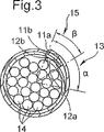
図3に明確に示されるように、このスリーブ10がケーブル14の束の周りにフィットされると、スリーブ10の第2の長手方向縁部10bは、導電性材料の層12と基材との間、より詳細には基材の第1の長手方向縁部11aとの間に挿入され、その結果、銅層12の長手方向縁部12a、12b間の接触によって、層12において電気的導通性を得ることができる。
As clearly shown in FIG. 3, when the
このように、スリーブ10の一方の長手方向縁部10aが、その他方の長手方向縁部10bに重なる重なり部分15が存在する。この重なり部分15は、管状基材11の長手方向軸線に対して60°から90゜の角度βの範囲を定める。
Thus, there is an overlapping
この重なり部分15は、保護されるべきケーブル14の束の直径に応じてより大きく又はより小さくなり、重要なことは、2つの長手方向縁部の間の良好な接触を有することである。
This
以下、本発明の電磁遮蔽スリーブの第2の実施形態を、図4及び図5を参照して説明する。 Hereinafter, a second embodiment of the electromagnetic shielding sleeve of the present invention will be described with reference to FIGS.
この実施形態において、基材11と導電性材料層12とは、2つの分割セグメント13及び13’で分離され、これらのうちの一方の分割セグメント13は、スリーブ10の第1の長手方向縁部10aに隣接し、他方の分割セグメント13’は、スリーブの第2の長手方向縁部10bに隣接する。
In this embodiment, the substrate 11 and the
従って、図5で明確に示されるように、これらの分割セグメント13、13’は、重なり部分15’で交互に配置され、その結果、導電層の縁部12a、12bがスリーブの内側で互いに接触するようになり、基材の長手方向縁部11a、11bがスリーブの外側で互いに接触するようになる。
Thus, as clearly shown in FIG. 5, these segmented
従って、上述の両方の実施形態において、導電性材料層12の電気的導通性がスリーブ10内部で形成され、基材11は、この接触部分を被覆して電気的接続を機械的に維持する。
Thus, in both embodiments described above, electrical continuity of the
このようにして信頼性があり効率的な遮蔽が得られ、遮蔽は航空用ケーブル束に好適である。 In this way a reliable and efficient shielding is obtained, which is suitable for aviation cable bundles.
この電磁遮蔽スリーブは、例えば、スリーブ10の長手方向に延びるステッチ16、16’、16”の1つ又はそれ以上の列を用いて、基材11に対して導電性材料層12を縫い合せることにより製造することができる。
The electromagnetic shielding sleeve can be formed by stitching the
ステッチ16’の列の少なくとも1つは、スリーブの1つの長手方向縁部10aから十分に離れており、長手方向縁部の近傍での基材と層12との分離を可能にする。
At least one of the rows of stitches 16 'is sufficiently far from one longitudinal edge 10a of the sleeve to allow separation of the substrate and
基材が熱成形された織布ストリップである場合には、銅編組は、熱成形段階の前に一連のステッチによって織布ストリップに固定される。 If the substrate is a thermoformed woven strip, the copper braid is secured to the woven strip by a series of stitches prior to the thermoforming step.
代替的に、このスリーブは、管状織りプロセスによって形成することができ、1つの層は銅線で作製され、且つ1つの層は織物フィラメントで作製される。この種の二重織りプロセスは、スリーブの製造中に銅層を織物フィラメント層に固定する操作を排除することになる。 Alternatively, the sleeve can be formed by a tubular weaving process, one layer made of copper wire and one layer made of woven filaments. This type of double weaving process eliminates the operation of securing the copper layer to the fabric filament layer during the manufacture of the sleeve.
従って、本発明の電磁遮蔽スリーブは、保護されるべきケーブル束が、例えばエンジン内に設置されて接続されている場合でも、効率的な遮蔽を達成し、且つケーブル束の周囲で使用するのが容易である。 Therefore, the electromagnetic shielding sleeve of the present invention achieves efficient shielding even when the cable bundle to be protected is installed and connected in an engine, for example, and is used around the cable bundle. Easy.
勿論、上述の実施形態に対しては、本発明の範囲を逸脱することなく多くの修正を行うことができる。 Of course, many modifications can be made to the above-described embodiments without departing from the scope of the present invention.
詳細には、分割セグメントがスリーブの両方の長手方向縁部に設けられている第2の実施形態において、基材と導電性材料層の両方を備える長手方向縁部の一方は、他方の長手方向縁部の基材及び伝導性材料層間に一体的に挿入することができる。 Specifically, in a second embodiment in which split segments are provided on both longitudinal edges of the sleeve, one of the longitudinal edges comprising both the substrate and the conductive material layer is in the other longitudinal direction. It can be integrally inserted between the edge substrate and the conductive material layer.
更に、導電性材料の2つの縁部12a、12bの重なりの小さな面積を生成して電気的導通性が形成することを満足する場合には、導電性材料層12の縁部12a,12bが、基材11の長手方向縁部11a、11bよりも長いか、又は短い距離を延びることができる。
Furthermore, if the
更に、管状スリーブは、自己巻き上がりストリップからではなく、ケーブル束の周囲に巻き上げられて、スリーブの長さに沿って分布したケーブル・タイ又はリングのような固定手段によって当該位置に保持されるように適合された平らなストリップから形成することができる。 Furthermore, the tubular sleeve is rolled up around the cable bundle rather than from a self-rolling strip so that it is held in place by fastening means such as cable ties or rings distributed along the length of the sleeve. It can be formed from a flat strip adapted to.
更にまた、基材は、編まれた又は編み組まれた布地のストリップから形成することができる。 Furthermore, the substrate can be formed from a strip of knitted or braided fabric.
同様に、導電性材料層は織られた銅線で作ることができる。 Similarly, the conductive material layer can be made of woven copper wire.
Claims (12)
前記基材(11)の内側表面(11c)に固定された導電性材料層(12)と、を備え、
前記層(12)が前記基材(11)の一方の長手方向縁部(11a)から他方の長手方向縁部(11b)に実質的に延びた長手方向スリット付き管状電磁遮蔽スリーブであって、
前記基材(11)と前記層(12)とが、前記基材(11)の少なくとも1つの第1の長手方向縁部(11a)において分割セグメント(13)で分離されており、前記基材(11)の第2の長手方向縁部(11b)が、前記基材(11)の第1の長手方向縁部(11a)と前記層(12)との間で前記分割セグメント(13)内にある、
ことを特徴とする電磁遮蔽スリーブ。A substrate (11);
A conductive material layer (12) fixed to the inner surface (11c) of the substrate (11),
A tubular electromagnetic shielding sleeve with a longitudinal slit, wherein the layer (12) extends substantially from one longitudinal edge (11a) of the substrate (11) to the other longitudinal edge (11b);
The substrate (11) and the layer (12) are separated by a segment (13) at at least one first longitudinal edge (11a) of the substrate (11), and the substrate The second longitudinal edge (11b) of (11) is within the segment (13) between the first longitudinal edge (11a) of the substrate (11) and the layer (12). In
An electromagnetic shielding sleeve.
請求項1に記載の電磁遮蔽スリーブ。The layers (12) are formed of interleaved copper wire structures;
The electromagnetic shielding sleeve according to claim 1.
請求項2に記載の電磁遮蔽スリーブ。The layer (12) is formed of braided copper wire;
The electromagnetic shielding sleeve according to claim 2.
請求項1ないし3の何れか1項に記載の電磁遮蔽スリーブ。The substrate (11) is manufactured in the form of a sheet thermoformed into self-rolling strips with overlap,
The electromagnetic shielding sleeve of any one of Claims 1 thru | or 3.
請求項1ないし4の何れか1項に記載の電磁遮蔽スリーブ。The substrate (11) is a fabric strip;
The electromagnetic shielding sleeve of any one of Claims 1 thru | or 4.
請求項1ないし5の何れかの1項に記載の電磁遮蔽スリーブ。The substrate is a woven fabric;
The electromagnetic shielding sleeve according to any one of claims 1 to 5.
請求項1ないし6の何れか1項に記載の電磁遮蔽スリーブ。The conductive material layer (12) is fixed to the substrate (11) by one or more rows (16, 16 ', 16 ") of stitches extending in the longitudinal direction of the sleeve (10). ,
The electromagnetic shielding sleeve of any one of Claims 1 thru | or 6.
請求項1ないし7の何れか1項に記載の電磁遮蔽スリーブ。The segment (13) defines a range of angles (α) approximately equal to 90 °;
The electromagnetic shielding sleeve according to claim 1.
請求項1ないし8の何れか1項に記載の電磁遮蔽スリーブ。An overlapping portion (15) of one longitudinal edge (10a) on the other longitudinal edge (10b) of the sleeve (10) defines an angle (β) of 60 ° to 90 °;
The electromagnetic shielding sleeve according to claim 1.
請求項1ないし9の何れか1項に記載の電磁遮蔽スリーブ。A second longitudinal edge (10b) of the sleeve (10) is configured to be inserted between the substrate (11) and the layer (12) in the split segment (13). ,
The electromagnetic shielding sleeve of any one of Claims 1 thru | or 9.
請求項1ないし9の何れか1項に記載の電磁遮蔽スリーブ。The substrate (11) and the layer (12) are formed on a first longitudinal edge (10a) of the sleeve (10) and a second longitudinal edge (10b) of the sleeve (10). Each separated on an adjacent split segment (13, 13 '),
The electromagnetic shielding sleeve of any one of Claims 1 thru | or 9.
Applications Claiming Priority (3)
| Application Number | Priority Date | Filing Date | Title |
|---|---|---|---|
| FR0303552A FR2853148B1 (en) | 2003-03-24 | 2003-03-24 | ELECTRO-MAGNETIC SHIELDING SHIELD, IN PARTICULAR FOR PROTECTING CABLE BEAMS IN AERONAUTICS. |
| FR03/03552 | 2003-03-24 | ||
| PCT/FR2004/000695 WO2004086582A2 (en) | 2003-03-24 | 2004-03-22 | Electromagnetic shielding sleeve which is intended, for example, to protect bundles of cables for use in aeronautics |
Publications (2)
| Publication Number | Publication Date |
|---|---|
| JP2006521669A JP2006521669A (en) | 2006-09-21 |
| JP4688107B2 true JP4688107B2 (en) | 2011-05-25 |
Family
ID=32947113
Family Applications (1)
| Application Number | Title | Priority Date | Filing Date |
|---|---|---|---|
| JP2006505743A Expired - Lifetime JP4688107B2 (en) | 2003-03-24 | 2004-03-22 | Electromagnetic shielding sleeve for the purpose of protecting cable bundles used for example in aviation technology |
Country Status (10)
| Country | Link |
|---|---|
| US (2) | US7235737B2 (en) |
| EP (1) | EP1606865B1 (en) |
| JP (1) | JP4688107B2 (en) |
| AT (1) | ATE362669T1 (en) |
| BR (1) | BRPI0408355B1 (en) |
| CA (1) | CA2519583C (en) |
| DE (1) | DE602004006505T8 (en) |
| ES (1) | ES2286648T3 (en) |
| FR (1) | FR2853148B1 (en) |
| WO (1) | WO2004086582A2 (en) |
Families Citing this family (36)
| Publication number | Priority date | Publication date | Assignee | Title |
|---|---|---|---|---|
| GB2432710B (en) * | 2005-11-29 | 2008-04-30 | Icore Internat Ltd | Electrical-cable shielding |
| AT503205B1 (en) * | 2006-01-18 | 2007-11-15 | Anton Dipl Ing Zahradnik | CASES FOR CABLE GUIDES |
| CN200990261Y (en) * | 2006-10-25 | 2007-12-12 | 上海益而益电器制造有限公司 | Electric source line with electricity leakage detecting conductor |
| CN101622123A (en) * | 2006-12-07 | 2010-01-06 | 费德罗-莫格尔动力系公司 | Protective sleeve assembly with support and method of manufacturing the same |
| US20080135119A1 (en) * | 2006-12-07 | 2008-06-12 | Takashi Tonooka | Protective sleeve assembly having a support member and method of construction |
| JP5174366B2 (en) * | 2007-03-28 | 2013-04-03 | 矢崎総業株式会社 | Electric wire protector and wire harness |
| FR2916081B1 (en) * | 2007-05-07 | 2009-09-25 | Fed Mogul Systems Prot Group S | ELECTROMAGNETIC PROTECTIVE SHEATH IN TEXTILE. |
| US9028937B2 (en) | 2008-01-07 | 2015-05-12 | Federal-Mogul Powertrain, Inc. | Multilayer protective textile sleeve and method of construction |
| DE102008020220A1 (en) * | 2008-04-22 | 2009-10-29 | Damm, Hans | Device for receiving individual electrical lines |
| US8747582B2 (en) * | 2008-09-05 | 2014-06-10 | Federal-Mogul Powertrain, Inc. | Self-wrapping textile sleeve with protective coating and method of construction thereof |
| US8925592B2 (en) | 2009-06-11 | 2015-01-06 | Federal-Mogul Powertrain, Inc. | Flexible, abrasion resistant textile sleeve and method of construction thereof |
| EP2440695B1 (en) * | 2009-06-11 | 2019-10-02 | Federal-Mogul Powertrain LLC | Flexible, abrasion resistant textile sleeve and method of construction thereof |
| WO2011009112A2 (en) * | 2009-07-17 | 2011-01-20 | Federal-Mogul Powertrain,Inc | Tri-layer knit fabric, thermal protective members formed therefrom and methods of construction thereof. |
| KR101749156B1 (en) * | 2009-10-07 | 2017-06-20 | 페더럴-모걸 파워트레인 엘엘씨 | Flexible textile sleeve with end fray resistant, protective coating and method of construction thereof |
| CN102763278A (en) * | 2010-02-12 | 2012-10-31 | 株式会社藤仓 | Leaky coaxial cable |
| EP2710696A1 (en) * | 2011-05-20 | 2014-03-26 | LAMIFLEX S.p.A. | Ultralight cable sheath for screening electrical and magnetic fields |
| JP5913842B2 (en) * | 2011-06-17 | 2016-04-27 | 矢崎総業株式会社 | Manufacturing method of shielded wire |
| US9362725B2 (en) | 2011-10-28 | 2016-06-07 | Milliken & Company | Electromagnetic shielded sleeve |
| ES2488403T3 (en) * | 2011-11-24 | 2014-08-27 | Relats, S.A. | Electromagnetic protection tube |
| JP5942703B2 (en) * | 2012-01-23 | 2016-06-29 | 株式会社オートネットワーク技術研究所 | Electromagnetic shield and wire harness |
| US8952274B2 (en) | 2012-07-10 | 2015-02-10 | Thomas & Betts International, Inc. | Sleeve for protecting wire or cable |
| ES2439818B1 (en) * | 2012-07-23 | 2014-12-29 | Relats, S.A. | TUBULAR PROTECTION COVER |
| US9633758B2 (en) | 2013-05-28 | 2017-04-25 | Federal-Mogul Powertrain, Inc. | Wrapped textile sleeve with bonded closure mechanism NAD method of construction thereof |
| US20150014047A1 (en) * | 2013-07-12 | 2015-01-15 | Topcon Medical Laser Systems, Inc. | Method and Apparatus for Electromagnetic Interference Protection |
| DE202013103659U1 (en) * | 2013-08-13 | 2014-11-14 | Rehau Ag + Co. | Textile fabric |
| DE202013104832U1 (en) * | 2013-10-29 | 2015-01-30 | Rehau Ag + Co. | Conduit |
| US10542645B2 (en) | 2015-04-17 | 2020-01-21 | Federal-Mogul Powertrain Llc | EMI protective sleeve and method of construction thereof |
| CN105845264A (en) * | 2016-05-06 | 2016-08-10 | 江苏通鼎光电科技有限公司 | Zipper bushing internal shielding railway digital signal cable |
| US10982355B2 (en) * | 2016-07-25 | 2021-04-20 | Federal-Mogul Powertrain Llc | Knit tubular protective sleeve and method of construction thereof |
| US11401631B2 (en) * | 2019-10-28 | 2022-08-02 | Federal-Mogul Powertrain Llc | Impact resistant, wrappable multilayered woven sleeve and method of construction thereof |
| US11219145B2 (en) * | 2019-11-05 | 2022-01-04 | Ls Cable & System Ltd. | Self-wrap electromagnetic wave shield tube |
| CN111740343B (en) * | 2020-07-10 | 2021-11-30 | 蔡金花 | New energy automobile cable bundling mechanism |
| CN115734602A (en) * | 2022-11-24 | 2023-03-03 | 深圳市宏炬科技有限公司 | Self-rolling type opening shielding sheath for special equipment and preparation method thereof |
| US12460324B2 (en) * | 2023-04-21 | 2025-11-04 | Systems Protection Group Us Llc | Wrappable, woven, abrasion and EMI resistant sleeve |
| US12156392B1 (en) * | 2023-07-11 | 2024-11-26 | Federal-Mogul Powertrain Llc | Self-wrapping, multilayer abrasion and EMI resistant sleeve and method of construction thereof |
| US20250309625A1 (en) * | 2024-04-02 | 2025-10-02 | Federal-Mogul Powertrain Llc | Multilayer, emi shielding, self-wrapping textile sleeve and method of construction thereof |
Family Cites Families (15)
| Publication number | Priority date | Publication date | Assignee | Title |
|---|---|---|---|---|
| US2358743A (en) * | 1941-04-16 | 1944-09-19 | Smith Franklin Elijah | Flexible hose |
| DE1247435B (en) * | 1966-09-13 | 1967-08-17 | Zippertubing Co | Protective cover for holding electrical conductors |
| US3612744A (en) * | 1969-02-27 | 1971-10-12 | Hughes Aircraft Co | Flexible flat conductor cable of variable electrical characteristics |
| DE3408220A1 (en) * | 1984-03-07 | 1985-09-12 | Telefunken electronic GmbH, 7100 Heilbronn | CONTROLLABLE INTEGRATOR |
| JPH0614326Y2 (en) * | 1988-10-24 | 1994-04-13 | 住友電気工業株式会社 | Flat cable with shield |
| JPH0443821U (en) * | 1990-08-17 | 1992-04-14 | ||
| JP2695298B2 (en) * | 1991-03-26 | 1997-12-24 | 日本電信電話株式会社 | Cable inlet electromagnetic shield cover structure |
| JPH04312311A (en) * | 1991-04-11 | 1992-11-04 | Furukawa Electric Co Ltd:The | Wiring protector and mounting method thereof |
| US5367123A (en) * | 1993-03-15 | 1994-11-22 | The Zippertubing Co. | Electrically conductive sheath for ribbon cable |
| JP3112830B2 (en) * | 1996-05-16 | 2000-11-27 | 矢崎総業株式会社 | Wire shield structure |
| JPH10224943A (en) * | 1997-01-31 | 1998-08-21 | Keihin Sokki Kk | Shield tube |
| JPH11121969A (en) * | 1997-10-17 | 1999-04-30 | Nishikawa Rubber Co Ltd | Insulation protection material for shielded wires |
| JPH11215642A (en) * | 1998-01-20 | 1999-08-06 | Denka Electron Kk | Shielded post-covering type tube |
| JPH11317116A (en) * | 1998-04-30 | 1999-11-16 | Tsuchiya Rubber Kk | Electromagnetic wave shield material, and electromagnetic wave shield sheet, wire and cable, and cable cover using this |
| DE10149071A1 (en) * | 2001-10-05 | 2003-04-17 | Tesa Ag | Process for sheathing elongated goods, such as cable sets in particular |
-
2003
- 2003-03-24 FR FR0303552A patent/FR2853148B1/en not_active Expired - Fee Related
-
2004
- 2004-03-22 US US10/550,727 patent/US7235737B2/en not_active Expired - Lifetime
- 2004-03-22 EP EP04742307A patent/EP1606865B1/en not_active Expired - Lifetime
- 2004-03-22 JP JP2006505743A patent/JP4688107B2/en not_active Expired - Lifetime
- 2004-03-22 AT AT04742307T patent/ATE362669T1/en active
- 2004-03-22 DE DE602004006505T patent/DE602004006505T8/en active Active
- 2004-03-22 CA CA2519583A patent/CA2519583C/en not_active Expired - Lifetime
- 2004-03-22 BR BRPI0408355-5A patent/BRPI0408355B1/en not_active IP Right Cessation
- 2004-03-22 WO PCT/FR2004/000695 patent/WO2004086582A2/en not_active Ceased
- 2004-03-22 ES ES04742307T patent/ES2286648T3/en not_active Expired - Lifetime
-
2007
- 2007-05-22 US US11/751,927 patent/US20080124976A1/en not_active Abandoned
Also Published As
| Publication number | Publication date |
|---|---|
| ATE362669T1 (en) | 2007-06-15 |
| EP1606865B1 (en) | 2007-05-16 |
| DE602004006505T2 (en) | 2008-01-17 |
| FR2853148B1 (en) | 2008-11-14 |
| EP1606865A2 (en) | 2005-12-21 |
| JP2006521669A (en) | 2006-09-21 |
| US7235737B2 (en) | 2007-06-26 |
| BRPI0408355A (en) | 2006-03-21 |
| WO2004086582A3 (en) | 2004-11-04 |
| DE602004006505T8 (en) | 2008-05-08 |
| US20060185872A1 (en) | 2006-08-24 |
| WO2004086582A2 (en) | 2004-10-07 |
| BRPI0408355B1 (en) | 2015-06-30 |
| ES2286648T3 (en) | 2007-12-01 |
| CA2519583A1 (en) | 2004-10-07 |
| US20080124976A1 (en) | 2008-05-29 |
| DE602004006505D1 (en) | 2007-06-28 |
| FR2853148A1 (en) | 2004-10-01 |
| CA2519583C (en) | 2013-01-15 |
Similar Documents
| Publication | Publication Date | Title |
|---|---|---|
| JP4688107B2 (en) | Electromagnetic shielding sleeve for the purpose of protecting cable bundles used for example in aviation technology | |
| EP3283675B1 (en) | Emi protective sleeve and method of construction thereof | |
| JP4740968B2 (en) | Extendable drain member for grounding a grounded RFI / EMI shield | |
| EP1999762B1 (en) | Protective sleeve fabricated with hybrid yarn having wire filaments and method of fabrication | |
| EP2474007B1 (en) | Protective sleeve fabricated with hybrid yarn | |
| JP6837959B2 (en) | Protective sleeve with bonded wire filaments and how to build it | |
| JP6191489B2 (en) | Electromagnetic shield parts and electric wires with electromagnetic shield parts | |
| EP3607119B1 (en) | Woven emi and abrasion resistant sleeve and method of construction thereof | |
| EP1964224A1 (en) | Electrical-cable shielding | |
| CN106660304A (en) | Protective sleeve with bonded wire filaments and methods of construction thereof | |
| US12156392B1 (en) | Self-wrapping, multilayer abrasion and EMI resistant sleeve and method of construction thereof | |
| US12002603B2 (en) | Dielectric, circumferentially continuous, multilayered textile sleeve and method of construction thereof | |
| JP7593828B2 (en) | Sheathing member for electric wire, wire harness, and wiring structure for wire harness | |
| US20250309625A1 (en) | Multilayer, emi shielding, self-wrapping textile sleeve and method of construction thereof | |
| WO2022124081A1 (en) | Braided member and wire harness |
Legal Events
| Date | Code | Title | Description |
|---|---|---|---|
| A621 | Written request for application examination |
Free format text: JAPANESE INTERMEDIATE CODE: A621 Effective date: 20070124 |
|
| A131 | Notification of reasons for refusal |
Free format text: JAPANESE INTERMEDIATE CODE: A131 Effective date: 20091102 |
|
| A601 | Written request for extension of time |
Free format text: JAPANESE INTERMEDIATE CODE: A601 Effective date: 20100120 |
|
| A602 | Written permission of extension of time |
Free format text: JAPANESE INTERMEDIATE CODE: A602 Effective date: 20100127 |
|
| A521 | Request for written amendment filed |
Free format text: JAPANESE INTERMEDIATE CODE: A523 Effective date: 20100430 |
|
| TRDD | Decision of grant or rejection written | ||
| A01 | Written decision to grant a patent or to grant a registration (utility model) |
Free format text: JAPANESE INTERMEDIATE CODE: A01 Effective date: 20110111 |
|
| A01 | Written decision to grant a patent or to grant a registration (utility model) |
Free format text: JAPANESE INTERMEDIATE CODE: A01 |
|
| A61 | First payment of annual fees (during grant procedure) |
Free format text: JAPANESE INTERMEDIATE CODE: A61 Effective date: 20110209 |
|
| R150 | Certificate of patent or registration of utility model |
Ref document number: 4688107 Country of ref document: JP Free format text: JAPANESE INTERMEDIATE CODE: R150 |
|
| FPAY | Renewal fee payment (event date is renewal date of database) |
Free format text: PAYMENT UNTIL: 20140225 Year of fee payment: 3 |
|
| R250 | Receipt of annual fees |
Free format text: JAPANESE INTERMEDIATE CODE: R250 |
|
| R250 | Receipt of annual fees |
Free format text: JAPANESE INTERMEDIATE CODE: R250 |
|
| R250 | Receipt of annual fees |
Free format text: JAPANESE INTERMEDIATE CODE: R250 |
|
| R250 | Receipt of annual fees |
Free format text: JAPANESE INTERMEDIATE CODE: R250 |
|
| R250 | Receipt of annual fees |
Free format text: JAPANESE INTERMEDIATE CODE: R250 |
|
| R250 | Receipt of annual fees |
Free format text: JAPANESE INTERMEDIATE CODE: R250 |
|
| R250 | Receipt of annual fees |
Free format text: JAPANESE INTERMEDIATE CODE: R250 |
|
| R250 | Receipt of annual fees |
Free format text: JAPANESE INTERMEDIATE CODE: R250 |
|
| R250 | Receipt of annual fees |
Free format text: JAPANESE INTERMEDIATE CODE: R250 |
|
| R250 | Receipt of annual fees |
Free format text: JAPANESE INTERMEDIATE CODE: R250 |
|
| R250 | Receipt of annual fees |
Free format text: JAPANESE INTERMEDIATE CODE: R250 |
|
| EXPY | Cancellation because of completion of term |