JP4668182B2 - Medical equipment - Google Patents
Medical equipment Download PDFInfo
- Publication number
- JP4668182B2 JP4668182B2 JP2006517543A JP2006517543A JP4668182B2 JP 4668182 B2 JP4668182 B2 JP 4668182B2 JP 2006517543 A JP2006517543 A JP 2006517543A JP 2006517543 A JP2006517543 A JP 2006517543A JP 4668182 B2 JP4668182 B2 JP 4668182B2
- Authority
- JP
- Japan
- Prior art keywords
- patch
- medical device
- tissue site
- target tissue
- cavity
- Prior art date
- Legal status (The legal status is an assumption and is not a legal conclusion. Google has not performed a legal analysis and makes no representation as to the accuracy of the status listed.)
- Expired - Fee Related
Links
Images


Classifications
-
- A—HUMAN NECESSITIES
- A61—MEDICAL OR VETERINARY SCIENCE; HYGIENE
- A61F—FILTERS IMPLANTABLE INTO BLOOD VESSELS; PROSTHESES; DEVICES PROVIDING PATENCY TO, OR PREVENTING COLLAPSING OF, TUBULAR STRUCTURES OF THE BODY, e.g. STENTS; ORTHOPAEDIC, NURSING OR CONTRACEPTIVE DEVICES; FOMENTATION; TREATMENT OR PROTECTION OF EYES OR EARS; BANDAGES, DRESSINGS OR ABSORBENT PADS; FIRST-AID KITS
- A61F7/00—Heating or cooling appliances for medical or therapeutic treatment of the human body
- A61F7/12—Devices for heating or cooling internal body cavities
-
- A—HUMAN NECESSITIES
- A61—MEDICAL OR VETERINARY SCIENCE; HYGIENE
- A61B—DIAGNOSIS; SURGERY; IDENTIFICATION
- A61B17/00—Surgical instruments, devices or methods
- A61B2017/00831—Material properties
- A61B2017/00867—Material properties shape memory effect
-
- A—HUMAN NECESSITIES
- A61—MEDICAL OR VETERINARY SCIENCE; HYGIENE
- A61F—FILTERS IMPLANTABLE INTO BLOOD VESSELS; PROSTHESES; DEVICES PROVIDING PATENCY TO, OR PREVENTING COLLAPSING OF, TUBULAR STRUCTURES OF THE BODY, e.g. STENTS; ORTHOPAEDIC, NURSING OR CONTRACEPTIVE DEVICES; FOMENTATION; TREATMENT OR PROTECTION OF EYES OR EARS; BANDAGES, DRESSINGS OR ABSORBENT PADS; FIRST-AID KITS
- A61F7/00—Heating or cooling appliances for medical or therapeutic treatment of the human body
- A61F7/12—Devices for heating or cooling internal body cavities
- A61F2007/126—Devices for heating or cooling internal body cavities for invasive application, e.g. for introducing into blood vessels
-
- A—HUMAN NECESSITIES
- A61—MEDICAL OR VETERINARY SCIENCE; HYGIENE
- A61F—FILTERS IMPLANTABLE INTO BLOOD VESSELS; PROSTHESES; DEVICES PROVIDING PATENCY TO, OR PREVENTING COLLAPSING OF, TUBULAR STRUCTURES OF THE BODY, e.g. STENTS; ORTHOPAEDIC, NURSING OR CONTRACEPTIVE DEVICES; FOMENTATION; TREATMENT OR PROTECTION OF EYES OR EARS; BANDAGES, DRESSINGS OR ABSORBENT PADS; FIRST-AID KITS
- A61F7/00—Heating or cooling appliances for medical or therapeutic treatment of the human body
- A61F7/10—Cooling bags, e.g. ice-bags
Landscapes
- Health & Medical Sciences (AREA)
- Vascular Medicine (AREA)
- Thermal Sciences (AREA)
- Engineering & Computer Science (AREA)
- Biomedical Technology (AREA)
- Heart & Thoracic Surgery (AREA)
- Physics & Mathematics (AREA)
- Life Sciences & Earth Sciences (AREA)
- Animal Behavior & Ethology (AREA)
- General Health & Medical Sciences (AREA)
- Public Health (AREA)
- Veterinary Medicine (AREA)
- Surgical Instruments (AREA)
- Thermotherapy And Cooling Therapy Devices (AREA)
Description
本発明は、体内組織を冷却する医療装置に関する。 The present invention relates to a medical device for cooling a body tissue .
冠動脈疾患のため心筋への血液循環が不十分になると、心筋虚血、さらに重篤な場合には急性心筋梗塞(AMI)が生じる可能性がある。血流閉塞部を除去した後、心臓内へ血液を早期に再灌流させることによって、心筋への損傷が激減することが証明されている。しかし、心臓内への血流の再開は、再灌流傷害を引き起こすおそれがある。再灌流傷害は、血流が不十分であった間に心筋上に老廃物が蓄積され、正常な血流が再開されたときにこれらの老廃物が血液中の酸素と反応することに起因すると考えられている。 Inadequate blood circulation to the myocardium due to coronary artery disease can lead to myocardial ischemia and, in severe cases, acute myocardial infarction (AMI). It has been demonstrated that damage to the myocardium is drastically reduced by removing blood flow occlusions and then quickly reperfusing blood into the heart. However, resumption of blood flow into the heart can cause reperfusion injury. Reperfusion injury is due to the accumulation of waste products on the myocardium while blood flow is inadequate and these waste products react with oxygen in the blood when normal blood flow is resumed. It is considered.
再灌流させる前に心筋組織を冷却することによって、心筋への再灌流傷害を低減させることが可能である。心筋組織を摂氏33度の温度まで、すなわち正常の体温よりも約4度低く穏やかに冷却することにより、おそらくは化学反応速度の低下、ならびに組織活性及び関連する代謝要求の低下によって保護効果がもたらされる。摂氏33度が目標冷却温度であるが、摂氏28度から36度の間の冷却もまた有益となり得る。 By cooling the myocardial tissue before reperfusion, it is possible to reduce reperfusion injury to the myocardium. Gently cooling the myocardial tissue to a temperature of 33 degrees Celsius, i.e., about 4 degrees below normal body temperature, will likely provide a protective effect, possibly by reducing the chemical reaction rate, as well as by reducing tissue activity and related metabolic demands. . Although 33 degrees Celsius is the target cooling temperature, cooling between 28 degrees and 36 degrees Celsius can also be beneficial.
心筋組織を冷却する一方法に、患者の心臓の上に氷嚢を配置する方法がある。別の方法としては、心膜穿刺を行い、標的となる心筋組織付近の心膜腔内に挿入したリザーバに冷却流体を供給するものがある。また、心筋組織の冷却は、標的組織に冷却溶液を灌流させることによっても実施することができる。遠位先端部に伝熱素子が配置されたカテーテルを血管中に挿入して、心臓内に流れ込みそこを巡る血液を冷却することもできる。また、患者の冠状静脈洞に配置されたカテーテルから心臓に冷却血液を供給することによって心筋組織を冷却することも可能である。
本発明は、体内、例えば心室内の標的組織部位を冷却する装置及び方法を提供する。 The present invention provides an apparatus and method for cooling a target tissue site within a body, eg, a ventricle.
一態様では、本発明は、体(身体)内に挿入し、体内の標的組織部位付近に配置可能な遠位端を有する細長い本体を含む医療装置を特徴とする。また、標的組織部位を冷却するために、細長い本体の遠位端から展開可能な構造体も有する医療装置も提供される。 In one aspect, the invention features a medical device that includes an elongate body having a distal end that is inserted into a body and can be positioned near a target tissue site within the body. A medical device is also provided that also has a structure deployable from the distal end of the elongate body to cool the target tissue site.
様々な実施形態では、以下の1つ又は複数の特徴が含まれ得る。この医療装置の細長い本体は、遠位端に展開可能な構造体が固定された細長い軸部を含むことができる。この医療装置の本体はまた、軸部に対して長手方向に動かすことができ、遠位側に動かすと展開可能な構造体を収容する細長い鞘部(スリーブ)を含むことができる。この装置の遠位端は、展開可能な構造体が非展開状態にあるとき、体管中を通して標的組織部位まで進めることができるが、展開可能な構造体が展開状態にあるときには、体管中を通して進めることができない。この細長い本体はさらに、細長い本体の遠位端が標的組織部位付近に配置される際に体外に残る近位端を含むことができる。 In various embodiments, one or more of the following features may be included. The elongate body of the medical device can include an elongate shaft having a deployable structure secured to the distal end. The body of the medical device can also include an elongate sheath (sleeve) that can be moved longitudinally relative to the shank and accommodates a deployable structure when moved distally. The distal end of the device can be advanced through the body vessel to the target tissue site when the deployable structure is in the undeployed state, but in the body tube when the deployable structure is in the deployed state. Can not proceed through. The elongate body can further include a proximal end that remains outside the body when the elongate body distal end is positioned near the target tissue site.
さらに、この展開可能な構造体は、組織部位に接触するように成形された表面を有するパッチと、組織部位に接触するパッチ表面を冷却するために、細長い本体中の管腔から流体を受け取る内部空洞とを含むことができる。この展開可能な構造体はまた、カップ形でもよく、この構造体は、体組織に接触する外周部を含むことができ、体組織とカップ形構造体の内側表面とによって境界が画定される空洞が形成される。実施形態では、展開可能な構造体は、入口にジュール・トムソン孔(Joule−Thompson orifice)を備えた内部空洞を有することができ、それによって、細長い本体中を通り、その孔を通り抜けて内部空洞内に供給される液体は気体に相変化する。 Further, the deployable structure includes a patch having a surface shaped to contact the tissue site and an interior that receives fluid from a lumen in the elongated body to cool the patch surface that contacts the tissue site. Cavities. The deployable structure may also be cup-shaped, the structure can include a perimeter that contacts the body tissue, and is a cavity bounded by the body tissue and the inner surface of the cup-shaped structure. Is formed. In an embodiment, the deployable structure can have an internal cavity with a Joule-Thompson orifice at the inlet, thereby passing through the elongated body and through the hole to the internal cavity. The liquid supplied inside changes phase to gas.
別の態様では、本発明は、体内に挿入し、当該体内の標的組織部位付近に配置可能な遠位端を有する細長い本体を備える医療装置を特徴とする。この装置は、細長い軸部の遠位端から展開可能な、標的組織部位を冷却するためのパッチを有する。このパッチは、標的組織部位に接触するように成形された表面を有する。 In another aspect, the invention features a medical device that includes an elongate body having a distal end that can be inserted into a body and positioned near a target tissue site within the body. The device has a patch for cooling a target tissue site deployable from the distal end of the elongated shaft. The patch has a surface that is shaped to contact the target tissue site.
さらに、このパッチは、形状記憶合金製の折畳み可能な枠を含むことができ、それによって、展開されると、パッチが拡張して標的組織部位に接触する表面を形成することになる。細長い軸部は、パッチの内部空洞に流体を供給する第1の管腔、及びパッチの内部空洞から流体を除去する第2の管腔を含むことができる。パッチの内部空洞には、その中を流体が流れる導管を含めることができ、この導管は、標的組織部位に接触しているパッチ表面に隣接して配置される。実施形態では、この医療装置はさらに、少なくとも1つの追加の、細長い本体の遠位端から展開可能なパッチを含むことができる。 In addition, the patch can include a foldable frame made of a shape memory alloy, so that when deployed, the patch will expand to form a surface that contacts the target tissue site. The elongate shaft can include a first lumen that supplies fluid to the internal cavity of the patch, and a second lumen that removes fluid from the internal cavity of the patch. The internal cavity of the patch can include a conduit through which fluid flows, the conduit being disposed adjacent to the patch surface that is in contact with the target tissue site. In embodiments, the medical device can further include at least one additional patch deployable from the distal end of the elongate body.
このパッチはまた、パッチ表面に隣接するとともに標的組織部位に接触するように配置された、組織部位を冷却するための熱電冷却素子を含むことができる。他の実施形態では、このパッチは、その入口にジュール・トムソン孔を備えた内部空洞を有することができ、それによって、細長い軸部中を通り、その孔を通り抜けて内部空洞内に供給される液体は気体に相変化する。 The patch can also include a thermoelectric cooling element for cooling the tissue site disposed adjacent to the patch surface and in contact with the target tissue site. In other embodiments, the patch can have an internal cavity with a Joule-Thomson hole at its inlet, thereby passing through the elongated shaft and through the hole into the internal cavity. The liquid changes to a gas phase.
この医療装置はさらに、パッチ表面に隣接して配置されたバルーンを含むことができ、このバルーンは標的組織部位に接触することはない。このバルーンは、パッチが展開され、標的組織部位付近に配置されたときに、パッチと体液とを隔離することができる。細長い本体中に、バルーンに膨張媒体を供給するための管腔を含めることができる。この医療装置はまた、細長い軸部の遠位端付近に、パッチが標的組織部位付近で展開されたときにパッチを係留させるための、体内組織に連結可能な係留(アンカー)機構を有することができる。また、標的組織部位に接触しているパッチの表面温度を感知する温度センサを含めることもできる。 The medical device can further include a balloon disposed adjacent to the patch surface, the balloon not contacting the target tissue site. The balloon can isolate the patch and body fluid when the patch is deployed and placed near the target tissue site. A lumen for supplying an inflation medium to the balloon can be included in the elongated body. The medical device may also have an anchoring mechanism near the distal end of the elongated shaft that is connectable to body tissue for anchoring the patch when the patch is deployed near the target tissue site. it can. A temperature sensor that senses the surface temperature of the patch in contact with the target tissue site can also be included.
別の態様では、本発明は、軸部中を長手方向に遠位端まで延びる流体移送管腔を有する細長い本体を含む医療装置を特徴とする。また、本体の遠位端から展開可能なカップ形構造体を含めることもでき、この構造体は、体組織に接触する外周部を有することができ、体組織とカップ形構造体の内側表面とによって境界が画定される空洞が形成される。この空洞は、体液移送管腔と流体連通しており、したがって、空洞に液体を、また空洞から流体を移送することが可能となる。 In another aspect, the invention features a medical device that includes an elongate body having a fluid transfer lumen extending longitudinally through a shaft to a distal end. It can also include a cup-shaped structure that can be deployed from the distal end of the body, the structure can have an outer periphery that contacts the body tissue, and the body tissue and the inner surface of the cup-shaped structure; Creates a cavity delimited by. This cavity is in fluid communication with the bodily fluid transfer lumen, thus allowing liquid to and from the cavity to be transferred.
さらに、このカップ形構造体は、形状記憶合金製の折畳み可能な枠を含むことができ、それによって、展開されると、カップ形構造体が拡張してカップ形状となることができる。このカップ形構造体の外周部には、体組織に接触するように配置された複数の小孔を設けることができ、減圧時にこれらの孔によって、カップ形構造体の外周部が体組織に固定されることになる。このカップ形構造体は、第1の層と第2の層との間に配置された膨張可能な空洞を備えた積層構造体を含むことができ、この構造体は、密封空洞内の流体から体液を隔離するように膨張可能である。細長い軸部は、膨張可能な空洞に膨張媒体を供給するための管腔を有することができる。この医療装置はまた、空洞に供給された流体の温度を感知する温度センサを含むこともできる。 In addition, the cup-shaped structure can include a foldable frame made of a shape memory alloy so that when deployed, the cup-shaped structure can expand into a cup shape. A plurality of small holes arranged so as to come into contact with the body tissue can be provided on the outer periphery of the cup-shaped structure, and the outer periphery of the cup-shaped structure is fixed to the body tissue by these holes during decompression. Will be. The cup-shaped structure can include a laminated structure with an inflatable cavity disposed between the first layer and the second layer, the structure from the fluid in the sealed cavity. Inflatable to isolate bodily fluids. The elongate shaft can have a lumen for supplying an inflation medium to the inflatable cavity. The medical device can also include a temperature sensor that senses the temperature of the fluid supplied to the cavity.
実施形態では他の特徴を含めることができる。例えば、この医療装置の細長い本体は、遠位端に展開可能なパッチ又はカップ形構造体が固定された細長い軸部と、その軸部に対して長手方向に動かすことができる細長い鞘部とを含むことができる。この鞘部を遠位側に動かすと、これらの構造体は鞘部内に収容されることになる。これらの構造体は、鞘部を軸部に対して近位側に動かすことによって、本体の遠位端から展開させることができ、したがってこの構造体は鞘部に収容された状態から露出することになる。いくつかの実施形態では、装置の遠位端は、構造体が非展開状態にあるときに、体管中を通して組織部位まで進めることができるが、構造体が展開状態にあるときには、体管中を通して進めることができない。 Embodiments can include other features. For example, the elongate body of the medical device includes an elongate shaft with a deployable patch or cup-shaped structure secured to the distal end, and an elongate sheath that can be moved longitudinally relative to the shaft. Can be included. When this sheath is moved distally, these structures will be contained within the sheath. These structures can be deployed from the distal end of the body by moving the sheath proximally with respect to the shank, so that the structure is exposed from being contained in the sheath. become. In some embodiments, the distal end of the device can be advanced through the body vessel to the tissue site when the structure is undeployed, but when the structure is in the body tube Can not proceed through.
本発明に関連する技術として、体内の標的組織部位を冷却する方法について説明する。この方法は、細長い本体と、この細長い本体の遠位端から展開可能な構造体とを有するカテーテルの遠位部分を体管内に導入する工程を含む。カテーテルの遠位部分が標的組織部位付近に配置されるとともに、展開可能な構造体が細長い本体から展開されて、この展開された構造体が標的組織部位に接触して配置される。標的組織部位を冷却するために、この展開された構造体が冷却される。 As a technique related to the present invention, a method for cooling a target tissue site in the body will be described. The method includes introducing a distal portion of a catheter having an elongated body and a structure deployable from a distal end of the elongated body into a body vessel. A distal portion of the catheter is positioned near the target tissue site, and a deployable structure is deployed from the elongate body and the deployed structure is placed in contact with the target tissue site. The deployed structure is cooled to cool the target tissue site.
さらに、この展開可能な構造体は、組織部位に接触するように成形された表面を有するパッチを含むことができる。この展開可能な構造体はまた、カップ形でもよく、この構造体は、体組織部位に接触する外周部を有することができ、体組織とカップの内側表面とによって、境界が画定された空洞を形成する。標的組織部位は心室内でもよく、その場合はカテーテルの遠位端が心室内に配置されてから構造体を展開させることができる。 Further, the deployable structure can include a patch having a surface shaped to contact the tissue site. The deployable structure may also be cup-shaped, and the structure may have a perimeter that contacts the body tissue site and defines a cavity delimited by the body tissue and the inner surface of the cup. Form. The target tissue site may be in the ventricle, in which case the structure can be deployed after the distal end of the catheter is placed in the ventricle.
本発明の1つ又は複数の実施形態の詳細を、添付の図面及び以下の説明に記載する。本発明のその他の特徴、目的、及び利点は、以下の説明及び図面、ならびに特許請求の範囲から明らかとなろう。各図面の参照符号は同じ要素を示す。 The details of one or more embodiments of the invention are set forth in the accompanying drawings and the description below. Other features, objects, and advantages of the invention will be apparent from the description and drawings, and from the claims. Reference numerals in the drawings indicate the same elements.
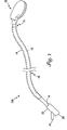
図1〜図5に示す医療装置100は、細長い本体10と、体内組織の標的部位を冷却するために、当該本体10の遠位端15から展開可能なバルーン形のパッチ20とを含む。図1は、展開状態にある装置100の全体を示す。標的組織部位を冷却するには、装置100を非展開状態(図1には示さず)で血管などの体腔内に挿入し、装置の遠位端15が心室内部などの標的組織部位付近に位置するまで進める。装置の遠位端15がそのように配置されたら、パッチ20を細長い本体10から展開させ、冷却すべき組織に接して配置することができる。次いで、冷却流体を装置100内に導入し、パッチ20の内部空洞30(図3に示す)中を循環させて、その組織に接触しているパッチ20の表面を冷却することができ、したがって、接触している組織部位を局部的に冷却することができる。
The
図1を参照すると、装置の本体10は細長い軸部12と、当該軸部12を収容する細長い鞘部14とを含む。パッチ20は、軸部12の遠位端18に取り付けられる(遠位端18は図3に示す)。細長い鞘部14は、軸部12に対して長手方向に、軸部12とは別個に動かすことができる。図1は展開状態にあるパッチ20を示し、この図では鞘部14が軸部12に対して近位側に動かされ、したがってパッチ20は鞘部14に収容された状態から露出している。パッチを非展開状態にするには、鞘部14を軸部12に対して遠位側に押し込むと、パッチ20が折り畳まれて鞘部14内に納まるようになる。図2は、パッチ20が折り畳まれ、細長い鞘部14内に収容されている装置100の遠位(先端)部分を示す。装置100は、図2に示す非展開状態で脈管を通して他の体内部位に進めることができるが、こうした部位には、パッチ20が展開された状態では、パッチ20が展開されたときの寸法及び形状を考えると、このように進めることはできない。
Referring to FIG. 1, the
再び図1を参照すると、軸部12の近位端16にアダプタ22が取り付けられ、このアダプタは装置100の使用中、患者の体外に残る。2つの管腔(ルーメン)40及び42(それらの先端部分を図3の断面図に示す)が、軸部の近位端16に取り付けられたアダプタ22から、軸部の遠位端18に取り付けられたパッチ20まで、軸部12中を通って長手方向に延びている。先に述べた冷却流体はアダプタ22内に導入することができ、その後、この流体は軸部12の第1の管腔40内に流れ込み、管腔40中を遠位側に流れ、パッチ20の内部空洞30内に流入する(図3の矢印で示す)。次いで、冷却流体は、パッチの内部空洞30から出て第2の管腔42に入る。流体はこの管腔42中を近位側に流れ、図1に示すアダプタ22に戻る。アダプタ22は、2つの開口24及び26を有する。冷却流体は、第1の開口24から装置100内に導入され、第2の開口26から装置を出ることができ、その逆も同様である。
Referring again to FIG. 1, an
パッチ20の内部空洞30中を循環させる流体は、空洞に入るとジュール・トムソン効果によって気体に位相変化する液体とすることができる。いくつかの実施形態では、第1の管腔40は、その遠位端にジュール・トムソン孔を含むことができ、したがって、管腔40中を流れる液体は、内部空洞30内に入ると気体状態に変化し、第2の管腔42は、空洞30から気体を除去するように機能する。あるいは、循環させる流体は、空洞中を循環させるときも液体状態のままでもよい。いくつかの実施形態では、パッチ20中に冷却流体を循環させると、パッチ20は折り畳まれた状態から膨張する。
The fluid that circulates in the
図2に示すように、パッチ20が折り畳まれ、細長い鞘部14内に収容されるとき、パッチ20は長手方向で巻くことができる。こうすることにより、パッチ20が展開されていないときの装置100の断面直径を最小限に抑える助けとなる。後でより詳細に説明する一実施形態では、パッチ20は、鞘部14を内部軸部12に対して遠位側に動かすことによって、パッチ20が膨張せずに鞘部14内に収容されたときに巻かれた状態となるように偏倚される内部枠を有するので、パッチ20は図2に示される、巻かれた状態になる。
As shown in FIG. 2, when the
図3に示すように、パッチ20は、先に論じた内部空洞30を形成するバルーン状の外側被覆31を有する。例示の実施形態では、パッチ20は、膨張すると、上面から見ると(図3のように)円形に、側面から見ると(図4の破線28で示すように)楕円形に見える平らなバルーン形となる。より具体的には、図4は、図3に示すパッチ20が膨張していないときのパッチ20の側面図を示し、破線28は、パッチ20が膨張したときに広がり得る範囲を示す。図3に示すように、バルーン状被覆31は、軸部12の遠位端18を覆って嵌合し取り付けられる近位開口を有する。したがって、軸部の管腔40及び42(図3に示す)はそれぞれ、バルーン状被覆31の内部空洞30内への開口を有し、したがって、先に述べたようにパッチ20の内部空洞30中を流体が循環できることになる。パッチ20の形状は、図3に示すような円形ではなく、代替として長方形、正方形、三角形、又は他の適当な形状に構成することもできる。パッチは、ナイロン、POC、PET、又は他の適当な材料などの薄い可撓性材料で作成することができる。
As shown in FIG. 3, the
図3を参照すると、パッチ20はまた、外側バルーン状構造31用の内部構造支持体を形成する(外周リング32及び長手方向の支持棒34から構成される)内部枠を含む。この内部枠32及び34によって、パッチ20は展開されたときに所望の形状となることができる。外周リング32は、その両端がそれぞれ、取付点36及び38で細長い軸部12の遠位端18に取り付けられたワイヤからなる。ワイヤ取付点36及び38は、軸部の遠位端18の両側にある。ワイヤ32は、これらの取付点36及び38から遠位側にループ状に延び、このループは内部空洞30の外周の寸法及び形状とほぼ一致する。長手方向支持棒34は、その近位端が取付点44で軸部の遠位端18の中心部分に取り付けられた細長い部材からなる。支持棒34は、この取付点44から外側バルーン状構造31の遠位側にある内側表面まで遠位側に延びる。
Referring to FIG. 3, the
支持ワイヤ32は、当該ワイヤ32が図3に示すリング形状にも、また図2に示す巻かれた形状にもなるように偏倚された、NITINOLなどの形状記憶材料から作成することができる。具体的には、外周リング32の両側面は、ワイヤ32が本体の外側鞘部14の空間内に押し込まれて収容されたときに、外周リングの両側面がそれぞれ反対方向に折り畳まれ、その結果パッチ20が図2の形状に巻かれるように偏倚されている。逆に、ワイヤ32の両側面は、本体の外側鞘部14に収容された状態から解放されたときに、ワイヤ32が図3に示すリング状の形状となるように外方に偏倚することもできる。
The
図3に示す形状以外の枠形状も企図される。例えば、パッチ20は、図3の実施形態のような単一の長手方向支持部材34を有するのではなく、軸部12の遠位端18から延びるとともに枠32まで達する複数の同様の部材を有する扇形形状とすることができる。別の構成では、部材34から半径方向に延びる腕部を設けて、魚骨形の形状を形成することもできる。他の実施形態では、部材34は省略することもできる。
Frame shapes other than those shown in FIG. 3 are also contemplated. For example, the
図3に示すように、装置100は、パッチ20の空洞30内に配置された感知素子54で温度を感知する温度センサ50を含む。この実施形態における感知素子54は、パッチのバルーン状被覆31の内側表面の、被覆31の外側表面が標的組織部位に接触する位置に取り付けられる。感知素子54をこのように配置することによって、装置100が冷却している組織部位の正確な温度測定が実現される。図示の例では、温度センサ50は熱電対である。この熱電対は、互いに絶縁されている異種材料製の2本の導線(図3には見やすいように1本の導線52のみ示す)から構成されている。これらの導線は、パッチの内部空洞30内に位置する遠位端の所で互いに接続されて、感知素子54として働く接合部を形成する。この接合部54は、接合部54の温度に応じて電圧差を生じる。導線52は、内部空洞30から軸部12中の管腔40を通ってアダプタ22内まで近位側に延び、アダプタ用開口26(図1に示す)からアダプタ22を出る。アダプタ用開口26から外に延びた2本の熱電対導線52の近位端に外部素子を接続することができ、それによって、2本の導線52の間の電圧差を測定し、次いでその電圧測定値を接合部54の温度指示に変換することができる。
As shown in FIG. 3, the
他の実施形態では、温度センサ50は、サーミスタ又は他の適当な温度感知機構でもよい。熱電対導線52は、管腔40中を通って延びるのではなく、管腔42中、又は軸部12内の追加の管腔(例示の実施形態には図示せず)中を通して延ばしてもよい。また、温度感知素子54は、必ずしも図3に示すようにバルーン状構造の内側表面に配置する必要はなく、別法としては、温度感知素子54は、他の位置、すなわち空洞30の内部又は装置100上の他のいずれの位置にも配置することができる。
In other embodiments, the
次に、図5を参照しながら、再灌流に伴う傷害を低減するために、装置100を使用して心筋組織を冷却することによってこの組織を保護する方法を説明する。図5には、大動脈弁106中を通って延び、患者の心臓102の左心室108内に配置された装置100の先端部分が示される。装置100の本体10から展開されたパッチ20が示されており、このパッチ20は心室隔壁110の心突部114に近い部位にある標的組織部位に接触するように配置される。このように配置された後、冷却流体をパッチ20に供給して標的組織部位を冷却することができる。
Next, with reference to FIG. 5, a method for protecting the myocardial tissue by cooling the myocardial tissue using the
装置100の先端部分を図5に示すように左心室108内に到達させるには、まず、装置100を図2に示すような非展開状態にする。次いで、装置100の遠位端15を経皮的に体内に導入し、大腿動脈など、患者の大動脈104に到達可能な、入れやすい(accessible)脈管中に導入する。装置100を、患者の大動脈104中を通して大動脈弁106まで進める。大動脈弁106は、血液を左心室108から大動脈104へと流す方向にのみ開き、この方向は、装置100が弁106を通って進む方向とは反対となる。したがって、装置100は、心収縮(縮小)の間、大動脈弁106が開位置に押しやられているときにのみ左心室108内に進めることができる。装置100は、装置100を弁106の所に配置し、血流の抵抗力が低減したときに装置100を進めることによって前進させることができる。あるいは、装置100は、この処置の間、患者の心電図をモニタすることによって、又は圧力指示を生理的にモニタすることによって、大動脈弁106の開弁時を求めて前進させることもできる。
In order to allow the distal end portion of the
装置100の遠位端15を左心室108内に進めた後、装置の遠位端15を心室中隔110の方に向ける。遠位端15を、中隔壁112に沿って心室108内を標的組織部位までさらに進めることができ、この例では、標的組織部位は、心臓102の心突部114付近の中隔壁112にある組織部位である。中隔壁112を案内として用いて左心室108内の他の部位を回避することによって、左心室108内の腱索組織又は乳頭組織への損傷を回避することができる。また、心室108中におけるパッチの移動は、パッチに付着した放射線不透過性マーカ(図示せず)を用いて行うことができる。装置100の遠位端15を標的組織部位付近に配置した後、鞘部14を軸部12(図5には示さず)に対して近位方向に動かすことによってパッチ20を展開させることができる。次いで、展開させたパッチ20を標的組織部位に接触して配置することができる。
After the
左心房(図示せず)から左心室108に入る血液によって、中隔壁112の表面上に下方に働く力が加わる。したがって、パッチ20が中隔壁112上に展開されると、血液がパッチ20を壁112に押し付けるようになる。この下方に働く力を利用して、標的組織部位上にパッチ20を配置する助けとすることができる。パッチ20は、パッチ表面が中隔壁112に沿って撓曲し従う(flex and conform)ことができるほど十分に可撓性のものとすることができ、したがってパッチ20の表面に接触する組織の表面積が増大する。パッチ表面が標的組織部位に接触した後、冷却流体をパッチ20に送達して組織部位を冷却することができる。
Blood entering the
パッチ20はまた、左心室108の前壁上に配置することも、また、前壁と中隔壁の両方に接触するように配置することもできる。こうした位置に配置すると、血流が低減したときに主に心筋梗塞の影響を受けやすい心臓の部位にうまくアクセスすることができる。また、左心室108内の他の位置でも有効な冷却を行うことができる。これらの有効な冷却位置は、心室108内の乳頭筋及び腱索の位置、ならびにこの処置で使用するパッチ20の寸法によって決まる。例えば、パッチ20が中隔壁108上に配置される実施形態では、パッチ20は約2cm×4cmである。
The
上述の処置は、心臓に流れる血液が不十分である間、及び心臓に流れる血流の閉塞部を除去する処置の前及びその間に行うことができる。血流の閉塞部を除去する処置には、例えば、溶骨性療法を用いて血管中の血栓性物質を溶解させる処置、ならびに直接的な経皮的冠動脈形成(PCTA)処置及びそれに関連するステントの埋込みがある。上述の方法を用いて、再灌流損傷を受けやすい心筋組織を標的として冷却するので、正常な血流が回復し、血液が心臓の罹患部位(effected area)に再灌流するとき、心筋への再灌流損傷は最小限に抑えられ、さらには解消されることになる。 The procedure described above can be performed while there is insufficient blood flowing to the heart and before and during the procedure to remove the blockage of blood flow flowing to the heart. Treatments that remove blood flow obstructions include, for example, treatments that dissolve thrombotic substances in blood vessels using osteolytic therapy, and direct percutaneous coronary angioplasty (PCTA) procedures and associated stents. There is an embedding. Using the method described above, cooling is targeted to reperfusion-damaged myocardial tissue so that when normal blood flow is restored and blood is reperfused into the affected area of the heart, Perfusion damage will be minimized and even eliminated.
この冷却方法は、右心室など心臓の他の部分にも使用することができる。また、膀胱や腸管など体内の他の中空器官内でも冷却を行うことができる。
図6〜図8は、異なる設計の展開可能な構造体を備えた医療装置200を示す。図6を参照すると、医療装置200は、細長い本体210と、、体内組織の標的部位を冷却するためのに、本体210の遠位端215から展開可能なカップ形構造体220とを含む。図6は、展開状態にある装置200の全体を示す。標的組織部位を冷却するには、装置200を非展開状態(図示せず)で体腔内に挿入し、装置の遠位端215が、心室内部などの標的組織部位付近に位置するまで進める。装置の遠位端215がそのように配置された後、カップ形構造体220を細長い本体210から展開させ、カップ形構造体220の開口側を標的組織部位に隣接させて標的組織部位を覆って配置することができる。言い換えれば、カップ形構造体220のリム構造部230が標的組織部位に接触して配置されることになる。カップ形構造体220をこのように配置することによって、標的組織部位とカップ形構造体220の内面とによって境界が画定される密封空洞が形成される。次いで、冷却流体を装置220内に導入し、この密封空洞中を循環させることができ、したがってこの冷却流体は標的組織部位に直接接触しその部位を冷却することになる。
This cooling method can also be used for other parts of the heart, such as the right ventricle. Cooling can also be performed in other hollow organs in the body such as the bladder and intestinal tract.
FIGS. 6-8 illustrate a
図6を参照すると、装置の本体210は、細長い軸部212、及び軸部212を収容する細長い鞘部214を含む。カップ形構造体220は、軸部212の遠位端218に取り付けられる(遠位端218を図8に示す)。細長い鞘部214は、軸部212に対して長手方向に、軸部212とは別個に動かすことができる。図6は、展開状態にあるカップ形構造体220を示し、この図では鞘部214が軸部212に対して近位側に動かされ、したがってカップ形構造体220は鞘部214に収容された状態から露出している。カップ形構造体220を非展開状態にするには、鞘部214を軸部212に対して遠位側に押し込むと、カップ形構造体220が折り畳まれて鞘部214内に納まるようになる。装置200は、この非展開状態で脈管中を進めることができる。
Referring to FIG. 6, the
軸部212の近位端216にアダプタ222が取り付けられ、このアダプタは装置200の使用中、患者の体外に残る。管腔258及び260(それらの先端部分を図8に示す)が、近位端216から遠位端218まで、軸部212中を通って長手方向に延びている。これらの管腔258及び260は、後述するように、カップ形構造体220に流体を送達するとともに、そこから流体を除去する。密封空洞中を循環する冷却流体は、アダプタ用開口224から軸部管腔258中を通して導入することができ、この管腔は遠位端の所で、その一部がカップ形構造体220によって形成されている密封空洞内に開口している。次いで、この流体は、密封空洞を出て軸部管腔260中を通りアダプタ用開口226から出る。この流体は、生理食塩水、血液、代用血液、又は体組織に接触する他のどんな流体でもよい。供給する流体の温度は、例えば摂氏5〜10度でよい。
An
標的組織部位を覆って配置されるリム構造部230は、リム構造部230の、組織表面に接触する底面上にいくつかの孔232を含む。図8にも示すこれらの孔232は、リム構造部230内の内部通路244(図7に示す)に通じる開口となっており、そこから軸部管腔256及び258ならびにアダプタ222へと通じている。孔232の所で吸引を行う減圧システムをアダプタ222に接続し、それによってリム構造部230と標的組織部位との間を密封することができる。
The
図7は、医療装置200の先端部分の断面図を示す。カップ形構造体220は、上側半球体状に成形され、外側層234、内側層236、及びこれら2つの層234と236との間に配設された空洞238を有する。細長い軸部212は、液体又は気体などの膨張媒体を空洞238に供給する管腔250を含む。空洞238に膨張媒体を充填することによって、カップ形構造体220は、外側層234と接触する体液を、密封空洞240に供給される冷却流体から隔離する。この隔離によって、この装置の冷却効果が全身に及ぶのが制限されるとともに標的冷却の効率が向上する。膨張媒体は、例えば、体温、又は体液を隔離するのに適した任意の温度で供給することができる。
FIG. 7 shows a cross-sectional view of the distal end portion of the
空洞238内には、2つの層234と236との間にいくつかの支柱242が挿入されている。これらの支柱242は、膨張媒体が空洞238内に供給されるように、層234と236とを分離して保持する。さらに、支柱242は、空洞238に膨張媒体が充填されたときに、内側層236が空洞240内にめり込むことを防止する。支柱242は、図8の装置200の底面図に示すように、カップ形構造体220の全体にわたって配置することができる。あるいは、支柱242は、カップ形構造体220が膨張したときに、層234及び236がその形状を十分保持することができる場合には、カップ形構造体から省略することもできる。
In the
図7を参照すると、カップ形構造体220のリム構造部230がカップ形構造体の外周に沿って配置されている。このリム構造部230は円形で、所望の形状に偏倚させたNITINOLなどの形状記憶材料から作成されている。この形状記憶材料のため、カップ形構造体220は、カップ形構造体が展開されたときに所望の形状となることができる。リム構造部230は、リム構造部230中を通って長手方向に延びるとともに、リム底面(図8に示す)にある孔232を介してアクセス可能な減圧通路244を含む。管腔254及び256を介して減圧通路244に減圧が加えられ、それによってリム構造部230と組織225との間が密封されることになる。この密封は、冷却流体が密封空洞240から漏れて血流に入り込むことを防止し、それと同時に血液が空洞240に入ることを防止する。他の密封方法を使用することもできる。例えば、組織表面225とリム230との境界面で、空洞240に供給された流体が凍結するほどリム構造部230を冷却することによって密封を行うこともできる。このようにしてリム構造部230を冷却すると、空洞240の外側の、組織225とリム構造部230との境界面付近に位置する血液をも凍結させることがある。
Referring to FIG. 7, the
空洞240内部の流体温度をモニタするために、装置200には温度センサ270(図8に示す)を含めることができ、このセンサはカップ形構造体220によって形成される密封空洞240内に配置することができる。図8の実施形態では、温度センサ270は、接合部272及び異種材料製の2本の導線274(1本の導線として示す)を有する熱電対である。導線274は、先に述べたように、空洞240から軸部212中の管腔258、管腔260、又は軸部中の追加の管腔中を通って近位側に延びている。他の実施形態では、温度センサ270は、サーミスタ又は他の適当な温度感知機構でよい。温度センサ270は、図8に示すように、リム構造部230の内部の、流体を空洞240に供給する管腔の出口付近、又は空洞240内の流体の温度を感知するのに適した他のどんな位置にも配置することができる。
To monitor the fluid temperature inside the
カップ形構造体220はまた、リム構造部230を支持するとともに補強する支持部材248を含むことができる。図8の実施形態では、部材248は、軸部212の遠位端218に取り付けられ、空洞240中を長手方向に延び、カップ形構造体220の内層236まで達している。他の例では、カップ形構造体220は、軸部212から延び、内層236まで達して扇形を成す、カップ形構造体をさらに支持する複数の同様の部材を含むことができる。あるいは、部材248から半径方向に延びて魚骨形を成す複数の腕部でもよい。他の実施形態では、部材248は省略することもできる。
The cup-shaped
図9は、異なる設計の展開可能な構造体を備えた別の医療装置300の先端部分の断面図を示す。図9に示す医療装置300は、パッチ320と、細長い本体の遠位端342から展開可能な隔離バルーン330とを含む。図9は、展開状態にある装置300を示す。先に述べた実施形態と同じく、この装置の本体は、それぞれ先に述べた実施形態と同様に機能して、展開可能な構造体を展開させるとともに格納する細長い軸部340及び相補的な細長い鞘部360を含み、この例では、展開可能な構造体はパッチ320及び隔離バルーン330の両方を含む。標的組織部位を冷却するには、他の実施形態で説明したものと同様に、パッチ320を標的組織部位に接して配置し、管腔315及び317を介して冷却流体をパッチ320中に循環させる。隔離バルーン330は、パッチ上面322に取り付けられており、管腔319から流体又は気体を充填することによってパッチ320中を循環する冷却流体から体液を隔離することができる。また、望むなら、隔離バルーン330から隔離媒体を除去するための追加の管腔をバルーンに設けることもできる。
FIG. 9 shows a cross-sectional view of the distal portion of another
また、この医療装置300には、隔離バルーン底面312とパッチ上面322との間に、軸部340から遠位側に延びる中空軸部334を含めることができる。医療装置300内のこの軸部334中の管腔(図示せず)を通して導線336を延ばし、パッチ320を標的組織部位に接して係留させるためにこの導線を組織のある部位内まで延ばすことができる。図9の実施形態では、導線336の遠位端は、組織のある部位にねじ込むことができるように螺旋形に形成されている。他の実施形態では、導線は、パッチ320の位置を固定するように様々な形に形成することができる。あるいは、軸部334及び導線336は、省略することもできる。
The
図10及び図11は、冷却流体をパッチ中に巡らせる流動回路又は流動導管を有する展開可能なパッチの代替実施形態を示す。図10の実施形態では、パッチ400は、パッチの内部空洞410の大部分にわたって蛇行する管402を含む。標的組織部位を冷却するには、開口406から開口408へと管402中を通して冷却流体を循環させる。図11の実施形態では、パッチ500は、格子状に構成された複数の流体通路502を含む。流体は、矢印で示すように、管腔504を介して、軸部510から長手方向に延びる中央流路512内に供給することができる。次いで、この流体は、中央通路512から、中央通路512に垂直方向に延びる複数の流路514に内に流れ込むことができる。その後、この流体は戻り流路516に沿って軸部510の方に還流し、管腔506及び508に流れ出ることができる。図10及び図11に示すパッチ400及び500は、実施可能な流動回路のほんの2例である。他の実施形態では、流動回路は、様々な形状及び構成を取ることができる。
10 and 11 illustrate an alternative embodiment of a deployable patch having a flow circuit or flow conduit that circulates cooling fluid through the patch. In the embodiment of FIG. 10, the
図12A及び図12Bは、標的組織部位610を冷却するための一連の熱電冷却(TEC)素子602を有するパッチ600の一部分を示す。これらのTEC602は、ペルチェ効果として知られる熱エネルギープロセスを利用して組織を冷却する。このプロセスを利用すると、電圧直流電源を素子602に印加して、素子602の片面から反対側の面に熱を移動させることができる。図12Aは、パッチ600の断面図である。図12Bは、パッチ600の一部分の上面図であり、素子602がパッチ600全体にわたってどのように間隔を置いて配置されているのかを示す。
12A and 12B show a portion of a
図12Aの実施形態では、素子602は、電気絶縁体612で包み込まれており、直列に接続されたn型半導体及びp型半導体(これらの半導体は図示せず)を含む。他の実施形態では、これらの半導体は他の適当な材料で置き換えることができる。これらの半導体はセラミック基板の間に配置されており、このセラミック基板は、素子602の両面606及び608上のセラミック基板に取り付けられたヒートシンクからこれらの導体を電気的に絶縁する(セラミック基板及びヒートシンクは図示せず)。素子602は、一方のヒートシンクが接触面606に隣接し、他方のヒートシンクが上面608に隣接するように配置されている。
In the embodiment of FIG. 12A,
直流電圧を素子602に印加すると、これらの半導体対に電流が流れるようになる。この電流によって、熱が接触面606付近のヒートシンクから上面608付近のヒートシンクに移動するようになる。このプロセスによって、接触面606は冷却され、それと同時に上面608は加熱される。パッチ600の接触面606を冷却することによって、標的組織部位610をも冷却することができる。
When a DC voltage is applied to the
いくつかの実施形態について説明してきたが、様々な改変形態が可能であることを理解されたい。例えば、上述の装置及び方法は、右心室、膀胱、及び腸管など、体内の他の組織を冷却するのにも使用することができる。したがって、その他の実施形態も以下の特許請求の範囲に含まれるものである。 Although several embodiments have been described, it should be understood that various modifications are possible. For example, the devices and methods described above can also be used to cool other tissues in the body, such as the right ventricle, bladder, and intestinal tract. Accordingly, other embodiments are within the scope of the following claims.
Claims (17)
前記細長い本体(340)の遠位端から展開可能であり、かつ、前記標的組織部位を冷却するために冷却流体を中に受け入れるための第1の空洞を有するパッチ(320)とを含み、前記パッチ(320)は、前記標的組織部位に接触するように成形された下面を有している医療装置において、
前記医療装置は、さらに、前記パッチ(320)とは別のバルーン(330)を含み、前記バルーン(330)は、底面(312)を有し、前記パッチ(320)の表面に隣接して配置され、前記パッチの下面が、前記パッチ(320)の上面(322)の反対側で、前記標的組織部位に接触するときに、前記標的組織部位に接触しないようになっており、前記バルーン(330)は、中に第2の空洞を有し、前記第2の空洞は、前記第1の空洞とは別のものであり、前記第2の空洞は、膨張媒体を受け入れて前記バルーン(330)を膨張させるようになっており、前記パッチ(320)が展開されて前記標的組織部位付近に配置されたときに、前記バルーン(330)は、前記パッチ(320)と体液との間を隔離する、
ことを特徴とする医療装置。An elongate body (340) having a distal end (342) that can be inserted into the body and is disposed near a target tissue site in the body;
A patch (320) deployable from a distal end of the elongate body (340) and having a first cavity for receiving a cooling fluid therein for cooling the target tissue site, The patch (320) is a medical device having a lower surface shaped to contact the target tissue site,
The medical device further includes a balloon (330) separate from the patch (320), the balloon (330) having a bottom surface (312) and disposed adjacent to a surface of the patch (320). The lower surface of the patch is not in contact with the target tissue site when contacting the target tissue site on the opposite side of the upper surface (322) of the patch (320), and the balloon (330 ) Has a second cavity therein, wherein the second cavity is separate from the first cavity, the second cavity receiving an inflation medium and receiving the balloon (330) being adapted to inflate the, when the patch (320) is positioned adjacent the target tissue site is expanded, the balloon (330) isolates between said patch (320) and fluid ,
A medical device characterized by that.
前記細長い本体は、さらに、前記軸部に対して長手方向に動かすことができる細長い鞘部(360)を有し、
前記細長い鞘部は、遠位側に動かすと、前記展開可能なパッチを収容するように構成される、
ことを特徴とする、請求項1に記載の医療装置。The elongate body has an elongate shaft (340), and the elongate shaft (340) has the deployable patch (320) attached to the distal end of the elongate shaft (340). And
The elongate body further comprises an elongate sheath (360) that can be moved longitudinally with respect to the shank,
The elongate sheath is configured to receive the deployable patch when moved distally;
The medical device according to claim 1, wherein:
前記パッチの前記第1の空洞に冷却流体を供給する第1の管腔(315)と、
前記パッチの前記第1の空洞から前記冷却流体を除去する第2の管腔(317)とを含む、
請求項1に記載の医療装置。The elongated shaft (340) is
A first lumen (315) for supplying cooling fluid to the first cavity of the patch;
A second lumen (317) for removing the cooling fluid from the first cavity of the patch;
The medical device according to claim 1.
Applications Claiming Priority (2)
| Application Number | Priority Date | Filing Date | Title |
|---|---|---|---|
| US10/603,705 US20040267338A1 (en) | 2003-06-25 | 2003-06-25 | Targeted tissue cooling within a body |
| PCT/US2004/019992 WO2005002478A2 (en) | 2003-06-25 | 2004-06-23 | Targeted tissue cooling within a body |
Publications (2)
| Publication Number | Publication Date |
|---|---|
| JP2007515991A JP2007515991A (en) | 2007-06-21 |
| JP4668182B2 true JP4668182B2 (en) | 2011-04-13 |
Family
ID=33539790
Family Applications (1)
| Application Number | Title | Priority Date | Filing Date |
|---|---|---|---|
| JP2006517543A Expired - Fee Related JP4668182B2 (en) | 2003-06-25 | 2004-06-23 | Medical equipment |
Country Status (5)
| Country | Link |
|---|---|
| US (1) | US20040267338A1 (en) |
| EP (1) | EP1646342A2 (en) |
| JP (1) | JP4668182B2 (en) |
| CA (1) | CA2530394C (en) |
| WO (1) | WO2005002478A2 (en) |
Families Citing this family (19)
| Publication number | Priority date | Publication date | Assignee | Title |
|---|---|---|---|---|
| US20040167467A1 (en) * | 2003-02-21 | 2004-08-26 | Kent Harrison | Delivering cooled fluid to sites inside the body |
| US7326195B2 (en) | 2003-11-18 | 2008-02-05 | Boston Scientific Scimed, Inc. | Targeted cooling of tissue within a body |
| US7963940B2 (en) * | 2005-08-22 | 2011-06-21 | Boston Scientific Scimed, Inc. | Local perfusion device |
| US7785289B2 (en) * | 2006-10-17 | 2010-08-31 | Boston Scientific Scimed, Inc. | Catheter with flexible, non-kinking elongate member |
| US20080125747A1 (en) * | 2006-11-28 | 2008-05-29 | Smith & Nephew, Inc.-Tn | Passive thermal spine catheter |
| US7949411B1 (en) | 2007-01-23 | 2011-05-24 | Pacesetter, Inc. | Epicardial lead |
| US7920928B1 (en) | 2007-01-31 | 2011-04-05 | Pacesetter, Inc. | Passive fixation for epicardial lead |
| WO2012012807A2 (en) * | 2010-07-23 | 2012-01-26 | Board Of Regents Of The University Of Texas Systems | Surgical cooling device |
| CN103826689B (en) | 2011-07-25 | 2016-04-13 | 纳鲁萨夫有限公司 | Non-invasive systems, devices and methods for selective brain cooling |
| DE102011057009B4 (en) * | 2011-12-23 | 2019-02-21 | Adceris Gmbh & Co. Kg | Medical device for endovascular cooling and / or heating of blood |
| DE102012101524B4 (en) * | 2012-02-24 | 2013-12-12 | Acandis Gmbh & Co. Kg | Medical heat exchanger for endovascular tempering of blood and arrangement with such a heat exchanger |
| IL219477A0 (en) | 2012-04-30 | 2012-07-31 | Berger Thermal Res Ltd | A method for coupling between catheter tip and tissue by icing their interface and apparatus therefor |
| DE102012111581B4 (en) * | 2012-11-29 | 2018-05-09 | Acandis Gmbh & Co. Kg | Medical tempering for endovascular tempering of blood and system with such a tempering |
| WO2014102754A1 (en) * | 2012-12-31 | 2014-07-03 | Krishnan Subramaniam C | Catheter for vascular imaging, method of imaging, and method for interventional procedure using the catheter |
| MX2019011996A (en) * | 2017-04-05 | 2020-01-20 | Miraki Innovation Think Tank Llc | Cold slurry containment. |
| WO2020036919A1 (en) * | 2018-08-14 | 2020-02-20 | Csa Medical, Inc. | Devices and methods for isolating a treatment region in the body from other regions |
| AU2020272238B2 (en) * | 2019-04-10 | 2025-05-22 | CleanCold Technologies LLC | Cooling and refrigeration based on vacuum-driven water evaporation |
| KR102316569B1 (en) * | 2019-10-10 | 2021-10-21 | 한양대학교 산학협력단 | Laparoscpoic apparatus and method for preventing ischemic organ damage using the same |
| WO2022170187A1 (en) * | 2021-02-05 | 2022-08-11 | Pyne Devaraj | Detachable balloon embolization device and methods |
Family Cites Families (52)
| Publication number | Priority date | Publication date | Assignee | Title |
|---|---|---|---|---|
| GB1438759A (en) * | 1972-06-02 | 1976-06-09 | Spembly Ltd | Cryo-surgical apparatus |
| US3859986A (en) * | 1973-06-20 | 1975-01-14 | Jiro Okada | Surgical device |
| DE2831199C3 (en) * | 1978-07-15 | 1981-01-08 | Erbe Elektromedizin Gmbh & Co Kg, 7400 Tuebingen | Cryosurgical device |
| US4531935A (en) * | 1983-01-13 | 1985-07-30 | Med-West, Incorporated | Cardioplegia/air aspiration cannula |
| JPS63260573A (en) * | 1987-04-17 | 1988-10-27 | オリンパス光学工業株式会社 | Diet balloon |
| US4860744A (en) * | 1987-11-02 | 1989-08-29 | Raj K. Anand | Thermoelectrically controlled heat medical catheter |
| US5147355A (en) * | 1988-09-23 | 1992-09-15 | Brigham And Womens Hospital | Cryoablation catheter and method of performing cryoablation |
| GB2226497B (en) * | 1988-12-01 | 1992-07-01 | Spembly Medical Ltd | Cryosurgical probe |
| US4946460A (en) * | 1989-04-26 | 1990-08-07 | Cryo Instruments, Inc. | Apparatus for cryosurgery |
| US5766151A (en) * | 1991-07-16 | 1998-06-16 | Heartport, Inc. | Endovascular system for arresting the heart |
| US5735290A (en) * | 1993-02-22 | 1998-04-07 | Heartport, Inc. | Methods and systems for performing thoracoscopic coronary bypass and other procedures |
| US6033383A (en) * | 1996-12-19 | 2000-03-07 | Ginsburg; Robert | Temperature regulating catheter and methods |
| US5837003A (en) * | 1993-02-10 | 1998-11-17 | Radiant Medical, Inc. | Method and apparatus for controlling a patient's body temperature by in situ blood temperature modification |
| US6620188B1 (en) * | 1998-08-24 | 2003-09-16 | Radiant Medical, Inc. | Methods and apparatus for regional and whole body temperature modification |
| US5799661A (en) * | 1993-02-22 | 1998-09-01 | Heartport, Inc. | Devices and methods for port-access multivessel coronary artery bypass surgery |
| US6161543A (en) * | 1993-02-22 | 2000-12-19 | Epicor, Inc. | Methods of epicardial ablation for creating a lesion around the pulmonary veins |
| US6530234B1 (en) * | 1995-10-12 | 2003-03-11 | Cryogen, Inc. | Precooling system for Joule-Thomson probe |
| US5925038A (en) * | 1996-01-19 | 1999-07-20 | Ep Technologies, Inc. | Expandable-collapsible electrode structures for capacitive coupling to tissue |
| US5846238A (en) * | 1996-01-19 | 1998-12-08 | Ep Technologies, Inc. | Expandable-collapsible electrode structures with distal end steering or manipulation |
| US5861021A (en) * | 1996-06-17 | 1999-01-19 | Urologix Inc | Microwave thermal therapy of cardiac tissue |
| US6206004B1 (en) * | 1996-12-06 | 2001-03-27 | Comedicus Incorporated | Treatment method via the pericardial space |
| WO2000032126A1 (en) * | 1997-02-27 | 2000-06-08 | Cryocath Technologies Inc. | Cryosurgical catheter |
| US5868735A (en) * | 1997-03-06 | 1999-02-09 | Scimed Life Systems, Inc. | Cryoplasty device and method |
| US6223085B1 (en) * | 1997-05-06 | 2001-04-24 | Urologix, Inc. | Device and method for preventing restenosis |
| US5971979A (en) * | 1997-12-02 | 1999-10-26 | Odyssey Technologies, Inc. | Method for cryogenic inhibition of hyperplasia |
| US6325818B1 (en) * | 1999-10-07 | 2001-12-04 | Innercool Therapies, Inc. | Inflatable cooling apparatus for selective organ hypothermia |
| US6261312B1 (en) * | 1998-06-23 | 2001-07-17 | Innercool Therapies, Inc. | Inflatable catheter for selective organ heating and cooling and method of using the same |
| US6558412B2 (en) * | 1998-01-23 | 2003-05-06 | Innercool Therapies, Inc. | Selective organ hypothermia method and apparatus |
| US6051019A (en) * | 1998-01-23 | 2000-04-18 | Del Mar Medical Technologies, Inc. | Selective organ hypothermia method and apparatus |
| US6042559A (en) * | 1998-02-24 | 2000-03-28 | Innercool Therapies, Inc. | Insulated catheter for selective organ perfusion |
| US6685732B2 (en) * | 1998-03-31 | 2004-02-03 | Innercool Therapies, Inc. | Method and device for performing cooling- or cryo-therapies for, e.g., angioplasty with reduced restenosis or pulmonary vein cell necrosis to inhibit atrial fibrillation employing microporous balloon |
| US6458150B1 (en) * | 1999-02-19 | 2002-10-01 | Alsius Corporation | Method and apparatus for patient temperature control |
| US6126684A (en) * | 1998-04-21 | 2000-10-03 | The Regents Of The University Of California | Indwelling heat exchange catheter and method of using same |
| US6645234B2 (en) * | 1998-04-21 | 2003-11-11 | Alsius Corporation | Cardiovascular guiding catheter with heat exchange properties and methods of use |
| US6241722B1 (en) * | 1998-06-17 | 2001-06-05 | Cryogen, Inc. | Cryogenic device, system and method of using same |
| US20020161351A1 (en) * | 1998-09-01 | 2002-10-31 | Samson Wilfred J. | Method and apparatus for treating acute myocardial infarction with selective hypothermic perfusion |
| US6248112B1 (en) * | 1998-09-30 | 2001-06-19 | C. R. Bard, Inc. | Implant delivery system |
| US6575933B1 (en) * | 1998-11-30 | 2003-06-10 | Cryocath Technologies Inc. | Mechanical support for an expandable membrane |
| US6146411A (en) * | 1998-12-24 | 2000-11-14 | Alsius Corporation | Cooling system for indwelling heat exchange catheter |
| US6514245B1 (en) * | 1999-03-15 | 2003-02-04 | Cryovascular Systems, Inc. | Safety cryotherapy catheter |
| US6648879B2 (en) * | 1999-02-24 | 2003-11-18 | Cryovascular Systems, Inc. | Safety cryotherapy catheter |
| US6432102B2 (en) * | 1999-03-15 | 2002-08-13 | Cryovascular Systems, Inc. | Cryosurgical fluid supply |
| US6428534B1 (en) * | 1999-02-24 | 2002-08-06 | Cryovascular Systems, Inc. | Cryogenic angioplasty catheter |
| US6231551B1 (en) * | 1999-03-01 | 2001-05-15 | Coaxia, Inc. | Partial aortic occlusion devices and methods for cerebral perfusion augmentation |
| US6436071B1 (en) * | 1999-06-08 | 2002-08-20 | The Trustees Of Columbia University In The City Of New York | Intravascular systems for corporeal cooling |
| US6358197B1 (en) * | 1999-08-13 | 2002-03-19 | Enteric Medical Technologies, Inc. | Apparatus for forming implants in gastrointestinal tract and kit for use therewith |
| US6575966B2 (en) * | 1999-08-23 | 2003-06-10 | Cryocath Technologies Inc. | Endovascular cryotreatment catheter |
| AU4523301A (en) * | 1999-12-14 | 2001-06-25 | Radiant Medical, Inc. | Method for reducing myocardial infarct by applicaton of intravascular hypothermia |
| DE10103289A1 (en) * | 2001-01-25 | 2002-08-01 | Patrick Schauerte | Device for the reversible cooling and heating of biological tissues |
| CA2461217A1 (en) * | 2001-09-27 | 2003-04-03 | Roni Zvuloni | Cryoplasty apparatus and method |
| US6866638B2 (en) * | 2002-08-12 | 2005-03-15 | Radiant Medical, Inc. | Temperature sensing system with retrograde sensor |
| US20040215177A1 (en) * | 2003-04-24 | 2004-10-28 | Scimed Life Systems, Inc. | Therapeutic apparatus having insulated region at the insertion area |
-
2003
- 2003-06-25 US US10/603,705 patent/US20040267338A1/en not_active Abandoned
-
2004
- 2004-06-23 EP EP04755865A patent/EP1646342A2/en not_active Withdrawn
- 2004-06-23 WO PCT/US2004/019992 patent/WO2005002478A2/en not_active Ceased
- 2004-06-23 JP JP2006517543A patent/JP4668182B2/en not_active Expired - Fee Related
- 2004-06-23 CA CA2530394A patent/CA2530394C/en not_active Expired - Fee Related
Also Published As
| Publication number | Publication date |
|---|---|
| WO2005002478A2 (en) | 2005-01-13 |
| CA2530394A1 (en) | 2005-01-13 |
| US20040267338A1 (en) | 2004-12-30 |
| CA2530394C (en) | 2012-07-31 |
| EP1646342A2 (en) | 2006-04-19 |
| JP2007515991A (en) | 2007-06-21 |
| WO2005002478A3 (en) | 2005-04-28 |
Similar Documents
| Publication | Publication Date | Title |
|---|---|---|
| JP4668182B2 (en) | Medical equipment | |
| CA2552165C (en) | Circumferential ablation device assembly with dual expandable members | |
| JP4210435B2 (en) | Irrigated removal instrument assembly | |
| US6905494B2 (en) | Method and device for performing cooling- or cryo-therapies for, e.g., angioplasty with reduced restenosis or pulmonary vein cell necrosis to inhibit atrial fibrillation employing tissue protection | |
| US8221407B2 (en) | Catheter with tissue protecting assembly | |
| US6656174B1 (en) | Devices and methods for creating lesions in blood vessels without obstructing blood flow | |
| US8475440B2 (en) | Wide area ablation of myocardial tissue | |
| US7438714B2 (en) | Vacuum-based catheter stabilizer | |
| ES2241868T3 (en) | MEDICAL DEVICE WITH SENSOR THAT COOPERS WITH A DILATABLE MEMBER. | |
| US20050059862A1 (en) | Cannula with integrated imaging and optical capability | |
| US20080086073A1 (en) | Multi-region staged inflation balloon | |
| JP2018038861A (en) | Catheter system for ablating cardiac arrhythmias | |
| CA2552198A1 (en) | Circumferential ablation device assembly with an expandable member | |
| JP2019514463A (en) | Balloon catheter | |
| US11116560B2 (en) | Balloon catheter | |
| JP2000503246A (en) | Apparatus and method for electrophysiological treatment of the heart | |
| JP2006513770A (en) | Delivery of cooled fluid to a location in the body | |
| WO2006020327A1 (en) | Cooling tissue inside the body | |
| US20170296262A1 (en) | Pulmonary-vein cork device with ablation guiding trench | |
| WO2003086253A2 (en) | Therapeutic hypothermia system with intracardiac heat exchange catheter and method of treating acute myocardial infarction | |
| JP2018000964A (en) | Catheter with micro-peltier cooling components |
Legal Events
| Date | Code | Title | Description |
|---|---|---|---|
| A621 | Written request for application examination |
Free format text: JAPANESE INTERMEDIATE CODE: A621 Effective date: 20070322 |
|
| RD02 | Notification of acceptance of power of attorney |
Free format text: JAPANESE INTERMEDIATE CODE: A7422 Effective date: 20090305 |
|
| RD03 | Notification of appointment of power of attorney |
Free format text: JAPANESE INTERMEDIATE CODE: A7423 Effective date: 20090305 |
|
| RD04 | Notification of resignation of power of attorney |
Free format text: JAPANESE INTERMEDIATE CODE: A7424 Effective date: 20090512 |
|
| A131 | Notification of reasons for refusal |
Free format text: JAPANESE INTERMEDIATE CODE: A131 Effective date: 20090928 |
|
| A601 | Written request for extension of time |
Free format text: JAPANESE INTERMEDIATE CODE: A601 Effective date: 20091225 |
|
| A602 | Written permission of extension of time |
Free format text: JAPANESE INTERMEDIATE CODE: A602 Effective date: 20100107 |
|
| A601 | Written request for extension of time |
Free format text: JAPANESE INTERMEDIATE CODE: A601 Effective date: 20100126 |
|
| A602 | Written permission of extension of time |
Free format text: JAPANESE INTERMEDIATE CODE: A602 Effective date: 20100202 |
|
| A601 | Written request for extension of time |
Free format text: JAPANESE INTERMEDIATE CODE: A601 Effective date: 20100301 |
|
| A602 | Written permission of extension of time |
Free format text: JAPANESE INTERMEDIATE CODE: A602 Effective date: 20100308 |
|
| A521 | Request for written amendment filed |
Free format text: JAPANESE INTERMEDIATE CODE: A523 Effective date: 20100329 |
|
| A131 | Notification of reasons for refusal |
Free format text: JAPANESE INTERMEDIATE CODE: A131 Effective date: 20100426 |
|
| A601 | Written request for extension of time |
Free format text: JAPANESE INTERMEDIATE CODE: A601 Effective date: 20100726 |
|
| A602 | Written permission of extension of time |
Free format text: JAPANESE INTERMEDIATE CODE: A602 Effective date: 20100802 |
|
| A521 | Request for written amendment filed |
Free format text: JAPANESE INTERMEDIATE CODE: A523 Effective date: 20101026 |
|
| TRDD | Decision of grant or rejection written | ||
| A01 | Written decision to grant a patent or to grant a registration (utility model) |
Free format text: JAPANESE INTERMEDIATE CODE: A01 Effective date: 20101213 |
|
| A01 | Written decision to grant a patent or to grant a registration (utility model) |
Free format text: JAPANESE INTERMEDIATE CODE: A01 |
|
| A61 | First payment of annual fees (during grant procedure) |
Free format text: JAPANESE INTERMEDIATE CODE: A61 Effective date: 20110112 |
|
| FPAY | Renewal fee payment (event date is renewal date of database) |
Free format text: PAYMENT UNTIL: 20140121 Year of fee payment: 3 |
|
| R150 | Certificate of patent or registration of utility model |
Free format text: JAPANESE INTERMEDIATE CODE: R150 |
|
| R250 | Receipt of annual fees |
Free format text: JAPANESE INTERMEDIATE CODE: R250 |
|
| R250 | Receipt of annual fees |
Free format text: JAPANESE INTERMEDIATE CODE: R250 |
|
| R250 | Receipt of annual fees |
Free format text: JAPANESE INTERMEDIATE CODE: R250 |
|
| R250 | Receipt of annual fees |
Free format text: JAPANESE INTERMEDIATE CODE: R250 |
|
| LAPS | Cancellation because of no payment of annual fees |