JP4660549B2 - Dosage setting mechanism with sequence control function - Google Patents
Dosage setting mechanism with sequence control function Download PDFInfo
- Publication number
- JP4660549B2 JP4660549B2 JP2007528552A JP2007528552A JP4660549B2 JP 4660549 B2 JP4660549 B2 JP 4660549B2 JP 2007528552 A JP2007528552 A JP 2007528552A JP 2007528552 A JP2007528552 A JP 2007528552A JP 4660549 B2 JP4660549 B2 JP 4660549B2
- Authority
- JP
- Japan
- Prior art keywords
- sleeve
- displaceable
- setting mechanism
- stopper
- dosage
- Prior art date
- Legal status (The legal status is an assumption and is not a legal conclusion. Google has not performed a legal analysis and makes no representation as to the accuracy of the status listed.)
- Expired - Fee Related
Links
Images


Classifications
-
- A—HUMAN NECESSITIES
- A61—MEDICAL OR VETERINARY SCIENCE; HYGIENE
- A61M—DEVICES FOR INTRODUCING MEDIA INTO, OR ONTO, THE BODY; DEVICES FOR TRANSDUCING BODY MEDIA OR FOR TAKING MEDIA FROM THE BODY; DEVICES FOR PRODUCING OR ENDING SLEEP OR STUPOR
- A61M5/00—Devices for bringing media into the body in a subcutaneous, intra-vascular or intramuscular way; Accessories therefor, e.g. filling or cleaning devices, arm-rests
- A61M5/178—Syringes
- A61M5/31—Details
- A61M5/315—Pistons; Piston-rods; Guiding, blocking or restricting the movement of the rod or piston; Appliances on the rod for facilitating dosing ; Dosing mechanisms
- A61M5/31565—Administration mechanisms, i.e. constructional features, modes of administering a dose
- A61M5/31576—Constructional features or modes of drive mechanisms for piston rods
- A61M5/31578—Constructional features or modes of drive mechanisms for piston rods based on axial translation, i.e. components directly operatively associated and axially moved with plunger rod
- A61M5/3158—Constructional features or modes of drive mechanisms for piston rods based on axial translation, i.e. components directly operatively associated and axially moved with plunger rod performed by axially moving actuator operated by user, e.g. an injection button
-
- A—HUMAN NECESSITIES
- A61—MEDICAL OR VETERINARY SCIENCE; HYGIENE
- A61M—DEVICES FOR INTRODUCING MEDIA INTO, OR ONTO, THE BODY; DEVICES FOR TRANSDUCING BODY MEDIA OR FOR TAKING MEDIA FROM THE BODY; DEVICES FOR PRODUCING OR ENDING SLEEP OR STUPOR
- A61M5/00—Devices for bringing media into the body in a subcutaneous, intra-vascular or intramuscular way; Accessories therefor, e.g. filling or cleaning devices, arm-rests
- A61M5/178—Syringes
- A61M5/31—Details
- A61M5/315—Pistons; Piston-rods; Guiding, blocking or restricting the movement of the rod or piston; Appliances on the rod for facilitating dosing ; Dosing mechanisms
- A61M5/31533—Dosing mechanisms, i.e. setting a dose
- A61M5/31545—Setting modes for dosing
- A61M5/31548—Mechanically operated dose setting member
- A61M5/31555—Mechanically operated dose setting member by purely axial movement of dose setting member, e.g. during setting or filling of a syringe
-
- A—HUMAN NECESSITIES
- A61—MEDICAL OR VETERINARY SCIENCE; HYGIENE
- A61M—DEVICES FOR INTRODUCING MEDIA INTO, OR ONTO, THE BODY; DEVICES FOR TRANSDUCING BODY MEDIA OR FOR TAKING MEDIA FROM THE BODY; DEVICES FOR PRODUCING OR ENDING SLEEP OR STUPOR
- A61M5/00—Devices for bringing media into the body in a subcutaneous, intra-vascular or intramuscular way; Accessories therefor, e.g. filling or cleaning devices, arm-rests
- A61M5/178—Syringes
- A61M5/31—Details
- A61M5/3146—Priming, e.g. purging, reducing backlash or clearance
-
- A—HUMAN NECESSITIES
- A61—MEDICAL OR VETERINARY SCIENCE; HYGIENE
- A61M—DEVICES FOR INTRODUCING MEDIA INTO, OR ONTO, THE BODY; DEVICES FOR TRANSDUCING BODY MEDIA OR FOR TAKING MEDIA FROM THE BODY; DEVICES FOR PRODUCING OR ENDING SLEEP OR STUPOR
- A61M5/00—Devices for bringing media into the body in a subcutaneous, intra-vascular or intramuscular way; Accessories therefor, e.g. filling or cleaning devices, arm-rests
- A61M5/178—Syringes
- A61M5/31—Details
- A61M5/315—Pistons; Piston-rods; Guiding, blocking or restricting the movement of the rod or piston; Appliances on the rod for facilitating dosing ; Dosing mechanisms
- A61M5/31533—Dosing mechanisms, i.e. setting a dose
- A61M5/31545—Setting modes for dosing
- A61M5/31548—Mechanically operated dose setting member
- A61M5/3156—Mechanically operated dose setting member using volume steps only adjustable in discrete intervals, i.e. individually distinct intervals
-
- A—HUMAN NECESSITIES
- A61—MEDICAL OR VETERINARY SCIENCE; HYGIENE
- A61M—DEVICES FOR INTRODUCING MEDIA INTO, OR ONTO, THE BODY; DEVICES FOR TRANSDUCING BODY MEDIA OR FOR TAKING MEDIA FROM THE BODY; DEVICES FOR PRODUCING OR ENDING SLEEP OR STUPOR
- A61M5/00—Devices for bringing media into the body in a subcutaneous, intra-vascular or intramuscular way; Accessories therefor, e.g. filling or cleaning devices, arm-rests
- A61M5/178—Syringes
- A61M5/31—Details
- A61M5/315—Pistons; Piston-rods; Guiding, blocking or restricting the movement of the rod or piston; Appliances on the rod for facilitating dosing ; Dosing mechanisms
- A61M5/31565—Administration mechanisms, i.e. constructional features, modes of administering a dose
- A61M5/3159—Dose expelling manners
- A61M5/31593—Multi-dose, i.e. individually set dose repeatedly administered from the same medicament reservoir
- A61M5/31595—Pre-defined multi-dose administration by repeated overcoming of means blocking the free advancing movement of piston rod, e.g. by tearing or de-blocking
Landscapes
- Health & Medical Sciences (AREA)
- Vascular Medicine (AREA)
- Engineering & Computer Science (AREA)
- Anesthesiology (AREA)
- Biomedical Technology (AREA)
- Heart & Thoracic Surgery (AREA)
- Hematology (AREA)
- Life Sciences & Earth Sciences (AREA)
- Animal Behavior & Ethology (AREA)
- General Health & Medical Sciences (AREA)
- Public Health (AREA)
- Veterinary Medicine (AREA)
- Infusion, Injection, And Reservoir Apparatuses (AREA)
- External Artificial Organs (AREA)
Description
本発明は、注射可能な製剤の設定した投薬分を注射装置から投与する投薬量設定機構、特に、例えば、注射装置内にてアンプルから物質を分与するとき、順序制御を実現してプライミング投薬分及びこのプライミング投薬分と相違する分与すべき投薬分を設定することを容易にするため使用される投薬量設定機構に関する。 The present invention relates to a dose setting mechanism for administering a set dosage of an injectable preparation from an injection device, and in particular, when dispensing a substance from an ampoule in the injection device, a sequence control is realized to perform priming And a dose setting mechanism used to facilitate setting the dose and the dose to be dispensed that is different from this priming dose.
インスリン又はホルモンのような医療物質又は医薬の投薬分を投与する設計とされた、例えば、注射ペンのような注射装置は、最初にプライミング操作と称される時間の間プライミング量を分与し、これによって注射装置の針から注射すべき特定の少量の製剤を突き出すことにより、空気及び残留する全ての物質はプライミング操作によって注射を実行せずに注射カニューレから排出される設計とされている。その後に、注射すべき物質のより標準の多量の投薬分を設定することができる。 An injection device, such as an injection pen, designed to administer a medical substance or pharmaceutical dosage such as insulin or hormone, initially dispenses a priming amount for a time referred to as a priming operation, This allows the air and all remaining material to be expelled from the injection cannula without performing the injection by a priming operation by ejecting a specific small amount of formulation to be injected from the needle of the injection device. Thereafter, a more standard large dose of the substance to be injected can be set.
既知の注射ペンにて、回転可能な投薬分計量供給スリーブが提供され、該回転可能な投薬分計量供給スリーブは、異なるストッパを有しており、また、例えば段付き要素の形態にて設けられる。歯付きバー又はプランジャロッドの異なる行程長さは、投薬分計量供給スリーブによって設定することができる。ユーザは、通常、少なくとも2つの異なる投薬分、すなわち、プライミングのために分与すべき少量の物質の投薬分、次に、投与すべき投薬分を設定し、その後、この投薬分を注射装置によって注射することになる。 With known injection pens, a rotatable dosage metering sleeve is provided, which has a different stopper and is provided, for example, in the form of a stepped element. . Different stroke lengths of the toothed bar or plunger rod can be set by means of a dosage metering sleeve. The user typically sets at least two different dosages, i.e., a dosage of a small amount of substance to be dispensed for priming, then a dosage to be administered, after which the dosage is dispensed by the injection device. Will be injected.
投与すべき物質の一定の予め規定された量又は投薬分を注射しなければならない状況のときでさえ、ユーザは、最初にプライミング量を設定することが依然として必要であり、その結果、ユーザの側にて不正確に操作し、例えば、投与すべき投薬分がプライミングのために使用されたり、又はプライミング投薬分が注射されることさえもある。 Even in situations where a certain pre-defined amount or dosage of a substance to be administered has to be injected, the user still needs to set the priming amount first, so that the user's side Inaccurate operation, for example, the dose to be administered may be used for priming, or even a priming dose may be injected.
本発明の1つの目的は、特に、プライミングする間、ユーザにとって注射装置の操作を便利なものにする、注射装置から注射可能な製剤の設定した投薬分を投与する投薬量設定機構を提案することである。 One object of the present invention is to propose a dosage setting mechanism for administering a set dosage of an injectable formulation from an injection device, which makes the operation of the injection device convenient for the user, especially during priming. It is.
この目的は、請求項1に記載した投薬量設定機構によって実現される。有益な実施の形態は従属請求項に記載されている。
設定した投薬分の注射可能な製剤を注射装置から投与すべく本発明により提案される投薬量設定機構は、外側スリーブと、該外側スリーブに対して変位可能である前方に変位可能なスリーブとを備えている。本発明の目的上、前方に変位可能なスリーブには、第一のストッパを有する少なくとも1つの変位可能な要素、好ましくは、可撓性の要素が設けられる。該第一のストッパは、外側スリーブの相補的なストッパに対向する位置にあり且つ、外側スリーブと前方に変位可能なスリーブとの間の相対的な動きを制限することができる。第一のストッパ手段を備える、本発明にて提案されるかかる変位可能な要素又は可撓性の要素を提供することは、例えば、プランジャを押すことにより、物質をアンプルから分与し得るように動くようなプロファイルにてプランジャロッド又は歯付きバー又は別の前方に変位可能な要素が設けられるならば、可撓性の要素又は該可撓性の要素に配置された位置決め片は、例えば、歯付き部の凹所内に位置して第一のストッパを次の位置、すなわち前方に変位可能なスリーブが外側スリーブに対して自由に動くことができるようにする位置まで動かすことを意味する。変位可能な要素又は可撓性の要素又は該要素に配設された位置決め片は、歯付きバーの傾斜路又は別のプロファイルを介して前方に変位可能なスリーブに対して押されるとき、換言すれば、例えば、歯付き側の傾斜路によって半径方向に向けて外方に押されるとき、前方に変位可能な要素に設けられた本発明により提案される第一のストッパは次の位置、すなわち外側スリーブと前方に変位可能なスリーブとの間の相対的な動きが外側スリーブに設けられた相補的なストッパが前方に変位可能なスリーブのストッパと反対方向に動くため、制限され、このため、当接したとき、その動きが停止される位置まで動くことができる。特に、外側スリーブの相補的なストッパが前方に変位可能なスリーブの第一のストッパに対向する位置に位置する迄、前方に変位可能なスリーブは動き、これにより前方に変位可能なスリーブの更なる動きを制限することを可能にするよう第一のストッパは、前方に変位可能なスリーブに配設されるものとする。別の選択肢は、第一のストッパは歯付きバーの傾斜路によって当接する位置まで押されず、前方に変位可能なスリーブが外側スリーブに対して動いた後、更なる動きを防止する妨害状態が実現されるよう配設されるようにすることである。本発明の意味において、ストッパは、2つの部分、すなわちスリーブの相対的な動きを制限し又は停止させることのできる任意の要素とすることができる。
This object is achieved by a dosage setting mechanism according to claim 1. Useful embodiments are described in the dependent claims.
The dosage setting mechanism proposed by the present invention to administer an injectable formulation for a set dosage from an injection device comprises an outer sleeve and a forwardly displaceable sleeve that is displaceable relative to the outer sleeve. I have. For the purposes of the present invention, the forwardly displaceable sleeve is provided with at least one displaceable element having a first stop, preferably a flexible element. The first stopper is in a position opposite the complementary stopper of the outer sleeve and can limit relative movement between the outer sleeve and the forwardly displaceable sleeve. Providing such a displaceable or flexible element proposed in the present invention with a first stopper means is such that the substance can be dispensed from the ampoule, for example by pushing the plunger. If a plunger rod or toothed bar or another forward-displaceable element is provided in a moving profile, the flexible element or the positioning piece arranged on the flexible element can be, for example, a tooth It means to move the first stopper, located in the recess of the hook, to the next position, i.e. a position allowing the forwardly displaceable sleeve to move freely with respect to the outer sleeve. In other words, when the displaceable element or the flexible element or the positioning piece arranged on the element is pushed against the forwardly displaceable sleeve via the ramp or another profile of the toothed bar For example, when pushed outward in a radial direction by a toothed ramp, the first stopper proposed by the present invention provided on the element displaceable forward is The relative movement between the sleeve and the forward-displaceable sleeve is limited because the complementary stopper provided on the outer sleeve moves in the opposite direction to the forward-displaceable sleeve stopper. When touched, it can move to a position where its movement is stopped. In particular, the forward-displaceable sleeve moves until the complementary stop of the outer sleeve is located opposite the first stop of the forward-displaceable sleeve, which further increases the forward-displaceable sleeve. The first stopper shall be arranged on a sleeve which can be displaced forward so as to be able to limit the movement. Another option is that the first stopper is not pushed to the position where it is abutted by the ramp of the toothed bar, and an obstructive state is achieved that prevents further movement after the forward-displaceable sleeve moves relative to the outer sleeve It is to be arranged as described above. In the sense of the present invention, the stopper can be any element that can limit or stop the relative movement of the two parts, the sleeve.
ユーザによる操作を容易にするためノブに接続することができる前方に変位可能なスリーブが、例えば、ノブを引き出すことにより、注射装置における引っ張り動作の一部として後方に引っ張られたとき、換言すれば、注射装置の分与端部と反対側の注射装置の一端に向けて引っ張られたとき、注射装置は、該装置が第一のストッパのため、外側スリーブを相補的なストッパに対向する位置となる迄のみ引っ張ることができる。このことは、前方に変位可能なスリーブにおけるストッパと外側スリーブの相補的なストッパとの間の距離が注射装置を引っ張る動作の最大の可能な距離、従って分与すべき物質の投薬分の最大量を決定することになることを意味する。プロファイル又は凹所は、僅かな短い部分的な距離にてのみ歯付きバーに設けられ、前方に変位可能なスリーブの可撓性の要素は、相対的に短い引っ張り動作の後、既に外方に押されており、その結果、少量のみが設定され、第一の排出又は分与操作のため、例えば、プライミングのため分与される。その結果、本発明により提案された投薬分の計量供給機構の自動的な制限動作は、ストッパの距離によって規定された第一の分与操作のため、ユーザがプライミング投薬分以上の投薬分を設定することができないことを確実にするから、ユーザは、最早、プライミング投薬分を別個に設定する必要はない。ある投薬分を注射することを目的とする後続の分与操作のため、歯付きバーの傾斜路の後方にてより長い凹所を歯付きバーに設け、分与すべきより多量の物質を計量供給し且つ、設定することができる。従って、最初に分与される投薬分の量を選ぶことは、本発明により提案された投薬量設定機構により自動的に制御され、このため、ユーザはプライミング投薬分自体を設定することを必要とせずに、少量の投薬分にてプライミング操作を実行し、次に、注射される投薬分を設定することができる。このため、ユーザが最早、プライミング投薬分を設定する選択をすることはなく、このことは、注射装置の不正確な操作又は不正確な設定をほぼ防止することができ、また、ユーザは、注射装置を使用するとき、操作手順を容易に制御することが可能であることを意味する。 In other words, when a forward-displaceable sleeve that can be connected to the knob for ease of operation by the user is pulled backwards as part of the pulling action in the injection device, for example by pulling out the knob, in other words And when pulled toward one end of the injection device opposite the dispensing end of the injection device, the injection device is positioned so that the outer sleeve is opposite the complementary stopper because the device is a first stop. It can only be pulled until. This means that the distance between the stopper in the forward-displaceable sleeve and the complementary stopper in the outer sleeve is the maximum possible distance for the action of pulling the injection device, and thus the maximum amount of substance to be dispensed. Means that you will decide. The profile or recess is provided in the toothed bar only at a slight short partial distance, and the flexible element of the sleeve which can be displaced forward is already outward after a relatively short pulling action. So that only a small amount is set and dispensed for the first discharge or dispensing operation, for example for priming. As a result, the automatic limit operation of the dosage metering mechanism proposed by the present invention is the first dispensing operation defined by the distance of the stopper, so that the user sets the dosage more than the priming dosage. The user no longer needs to set the priming dose separately to ensure that it cannot be done. For subsequent dispensing operations aimed at injecting a certain dose, the toothed bar has a longer recess behind the toothed bar ramp to weigh more material to be dispensed Can be supplied and set. Therefore, the choice of the first dose to be dispensed is automatically controlled by the dose setting mechanism proposed by the present invention, which requires the user to set the priming dose itself. Instead, a priming operation can be performed with a small dosage, and then the dosage to be injected can be set. Thus, the user no longer chooses to set the priming dose, which can largely prevent incorrect operation or incorrect setting of the injection device, and the user can When using the device, it means that the operating procedure can be easily controlled.
本発明により提案される外側スリーブは、前方に変位可能なスリーブの回りに装着するか又はこれと代替的に、前方に変位可能なスリーブの内部に装着し、また、注射装置の外面と接続し又は注射装置の少なくとも一部を形成するようにすることが望ましい一方、前方に変位可能なスリーブは、例えば、ノブのような、設定要素と接続されることが望ましい。 The outer sleeve proposed by the present invention is mounted around the forward-displaceable sleeve or, alternatively, is mounted inside the forward-displaceable sleeve and is connected to the outer surface of the injection device. Alternatively, it may be desirable to form at least part of the injection device, while the forwardly displaceable sleeve is preferably connected to a setting element, such as a knob.
前方に変位可能なスリーブに2つ又はより多くの可撓性の要素を設け、また、可撓性の要素は、例えば、弾性アームの形態にて設け、該弾性アームは、前方に変位可能なスリーブの切欠き又はオリフィス内に配設され、また、当初の状態において、歯付きバー又はプランジャロッドの方向に向けて押されることが望ましい。該歯付きバー又はプランジャロッドは、例えば、前方に変位可能なスリーブ内にて案内されるようにする。前方に変位可能なスリーブ、例えばアームに位置決め片が設けられる。この場合、位置決め片は、歯付きバー又はプランジャロッドの方向を向くことが望ましく、換言すれば、例えば、ほぼ円筒状の形状の前方に変位可能なスリーブを使用するならば、内方に向けることができる。 Two or more flexible elements are provided on the forwardly displaceable sleeve, and the flexible elements are provided, for example, in the form of elastic arms, which are displaceable forwards It is preferably disposed in the notch or orifice of the sleeve and, in its initial state, pushed towards the toothed bar or plunger rod. The toothed bar or plunger rod is guided, for example, in a sleeve which can be displaced forward. A positioning piece is provided on a sleeve that can be displaced forward, for example, an arm. In this case, it is desirable for the positioning piece to face the toothed bar or the plunger rod, in other words, for example if it uses a generally cylindrically shaped forward-displaceable sleeve, it is directed inward. Can do.
可撓性の要素又は前方に変位可能なスリーブに設けられた第一のストッパは、ほぼ円筒状の形状の前方に変位可能なスリーブを使用するならば、内方及び外方の双方を向くようにし、また、例えば、耳状突起又はカムの形態にて提供し、これによりカムが外側スリーブの協働する相補的なストッパと当接するように動いて、外側スリーブに摺動可能に取り付けられた前方に変位可能なスリーブが例えば、軸方向に向けて相対的に動くが、ストッパが互いに当たって、これにより、例えば、プライミング投薬量を自動的に設定する迄のみ、動くことを許容する。 The first stop provided on the flexible element or forwardly displaceable sleeve will face both inward and outward if a generally cylindrically forward displaceable sleeve is used. And provided, for example, in the form of an ear or a cam, so that the cam moves to abut the cooperating complementary stopper of the outer sleeve and is slidably attached to the outer sleeve The forwardly displaceable sleeve, for example, moves relatively in the axial direction, but the stoppers strike each other, thereby allowing it to move only until, for example, the priming dosage is automatically set.
例えば、突き出す耳状突起又はカムの形態にて、少なくとも第二のストッパを前方に変位可能なスリーブに更に提供する。この場合、前方に変位可能なスリーブが第一のストッパにより制限されないならば、第二のストッパは、外側スリーブと前方に変位可能なスリーブとの間の相対的な動きを制限することができることが好ましい。その上に第一のストッパが配設された前方に変位可能なスリーブの可撓性の要素が可撓性の要素の偏倚動作のため、歯付きバーの凹所内に位置し、これによりプライミング投薬分よりも大きい投薬分を設定することを可能にする場合、例えば、前方に変位可能なスリーブの第二のストッパと外側スリーブの相補的なストッパとの間の距離に基づいて、注射操作のための最大の投薬分設定量を特定することが可能である。第一及び第二のストッパは、前方に変位可能なスリーブの軸方向に向けて互いに変位状態にて配設され、また、外側スリーブの同一の又はこれと代替的に異なるストッパと協働するようにすることが好ましい。 For example, in the form of a protruding lug or cam, at least a second stopper is further provided on the sleeve which can be displaced forward. In this case, if the forward-displaceable sleeve is not limited by the first stopper, the second stopper can limit the relative movement between the outer sleeve and the forward-displaceable sleeve. preferable. The flexible element of the forwardly displaceable sleeve, on which the first stopper is arranged, is located in the recess of the toothed bar due to the biasing movement of the flexible element, whereby the priming medication For example, based on the distance between the second stopper of the sleeve that can be displaced forward and the complementary stopper of the outer sleeve, it is possible to set a dosage larger than the minute. It is possible to specify the maximum dose setting amount. The first and second stoppers are arranged in a mutually displaced state in the axial direction of the forwardly displaceable sleeve and cooperate with the same or alternatively different stoppers of the outer sleeve. It is preferable to make it.
本発明は、外側スリーブ及び(又は)前方に変位可能なスリーブによって、好ましくは前方に変位可能なスリーブ内を案内される歯付きバーを備え、また、分与プロファイルを画成することのできる少なくとも1つ、好ましくは2つ又はより多くの凹所を有する、上述した型式の投薬量設定機構に更に関する。少なくとも2つの凹所が、例えば歯付きバー又はプランジャロッドの軸方向に向けて一方が他方の後となるように設けられるならば、これらの個別の凹所は傾斜路又は隆起領域によって互いに分離され、このため、凹所内に位置する前方に変位可能なスリーブの可撓性要素の位置決め片をかかる傾斜路によって歯付きバー又はプランジャロッドの中間軸線から外方に押すことができる。この場合、前方に変位可能なスリーブに、また、好ましくは可撓性の要素に設けられた第一のストッパは、歯付きバーから半径方向外方に押されて、外側スリーブの相補的なストッパと共に、注射装置の引っ張り動作を制限し、プライミング投薬分を設定し又は一定にすることができる。原理上、単一の凹所のみを歯付きバーに設けることができ、この場合、前方に変位可能なスリーブの可撓性の要素は、プライミング後に配置し、第一のストッパは別の投薬分の設定を実行することができないようにする。 The invention comprises a toothed bar guided by an outer sleeve and / or a forwardly displaceable sleeve, preferably in a forwardly displaceable sleeve, and at least capable of defining a dispensing profile It further relates to a dosage setting mechanism of the type described above having one, preferably two or more recesses. If at least two recesses are provided, for example in the axial direction of a toothed bar or plunger rod, one behind the other, these individual recesses are separated from each other by a ramp or a raised area. Thus, the positioning piece of the forward-displaceable sleeve flexible element located in the recess can be pushed outwardly from the intermediate axis of the toothed bar or plunger rod by such a ramp. In this case, the first stopper provided on the forwardly displaceable sleeve, and preferably on the flexible element, is pushed radially outward from the toothed bar so as to be complementary to the outer sleeve. At the same time, the pulling action of the injection device can be limited and the priming dose can be set or made constant. In principle, only a single recess can be provided in the toothed bar, in which case the forwardly displaceable flexible element of the sleeve is placed after priming and the first stopper is a separate dosage. The setting of cannot be executed.
外側スリーブ及び(又は)前方に変位可能なスリーブ又は該前方に変位可能なスリーブと接続された案内片に捕捉要素が設けられることが好ましい。該捕捉片は、弾性要素又は反発性要素又はアームに取り付けられることが望ましく、この場合、捕捉要素は、その内部に捕捉要素が位置する歯付きバーが一方向に向けて相対的に動くのを許容するが、反対方向への動きは妨害するような設計とされることが好ましい。 Preferably, the outer sleeve and / or the forwardly displaceable sleeve or the guide piece connected to the forwardly displaceable sleeve is provided with a capture element. The capture piece is preferably attached to an elastic element or a repulsive element or arm, in which case the capture element has a relative movement in one direction of a toothed bar in which the capture element is located. It is preferably designed to allow, but prevent movement in the opposite direction.
捕捉要素は、これらの捕捉要素が歯付きバーの協働する凹所又は歯部内に位置し、歯付きバーを外側スリーブ又は案内片に対し又は前方に変位可能なスリーブに対して注射装置の分与オリフィスに向けて動かすことができるような設計とされることが好ましい。 The capture elements are located in the cooperating recesses or teeth of the toothed bars, and are separated by the injection device relative to the outer sleeve or guide piece or the sleeve that can be displaced forward. Preferably, the design is such that it can be moved towards the given orifice.
別の形態のため、本発明は、上述した型式の投薬量設定機構を有する注射装置に関する。
本発明は、上述した型式の注射装置から注射可能な製剤の設定量を分与するプライミング又は準備を行う方法であって、前方に変位可能なスリーブの第一のストッパが外側スリーブの相補的なストッパと当接することにより、第一の所定の距離の後、注射装置の第一の装着動作が制限され、また、第一の投薬分、例えばプライミング投薬分は、好ましくはプライミング目的のため歯付きバー又はプランジャロッドを押すことにより分与され、これにより前方に変位可能なスリーブの第一のストッパによる外側スリーブと前方に変位可能なスリーブとの間の相対的な動きに対する制限がプライミング投薬分を分与する間、又は分与した後に解放されるようにした上記の方法に更に関する。
In another form, the invention relates to an injection device having a dosage setting mechanism of the type described above.
The present invention provides a priming or preparation method for dispensing a set amount of injectable formulation from an injection device of the type described above, wherein the forwardly displaceable sleeve first stopper is complementary to the outer sleeve. By abutting the stopper, after the first predetermined distance, the first mounting movement of the injection device is limited, and the first dosage, eg priming dosage, is preferably toothed for priming purposes A restriction on the relative movement between the outer sleeve and the forward displaceable sleeve by the first stop of the forward displaceable sleeve is dispensed by pushing the bar or plunger rod, thereby reducing the priming dose. It further relates to the above-described method which is released during or after dispensing.
本発明は、一例としての実施の形態に関して説明する。 The present invention will be described with reference to exemplary embodiments.
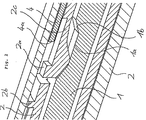
図1Aには、例えば、注射装置の後端を構成し、頂面図にてのみ概略図的に示した歯部分1dを有する歯付きバー1が前方に変位可能なスリーブ2内に配設され、該スリーブは図1Aの左側部に示した前端によってアンプル(図示せず)のストッパに対して押すことができ、これにより歯付きバー1を図1Aの左方向に向けて動かし、これにより注射装置の分与作用が行われるようにした、本発明により提案される投薬量設定機構の基本位置が示されている。前方に変位可能なスリーブ2が歯付き部分1の回りに配設されている。該スリーブは、本発明により提案された可撓性のアーム又はスナッパー2cを有している。該可撓性のアーム又はスナッパーは、図2及び図3に示すように、前方に変位可能なスリーブ2の開口部内に設けられ、半径方向内方又は外方に動くことができる。該アーム又はスナッパーは、図1Aに示した基本位置にあるとき、歯付きバー1の第一の凹所1a内に位置し、このとき、可撓性のアーム2cは図示した基本位置にて偏倚されない。このことは、前方に変位可能なスリーブ2が例えばプラスチックで出来ている場合、予め偏倚したスナッパー2cの張力は時間の経過に伴って弛緩するから、有益なことである。図1Aの左側における図示した前端において、前方に変位可能なスリーブ2は、例えば、弾性アーム2eのような弾性要素を有しており、該弾性要素の前端には、内方を向いた捕捉要素2c′が設けられている。該捕捉要素は、歯付きバー1の凹所又は歯部分1d内に位置して、このため図1Aに示すように、歯付きバー1は注射装置の分与方向に向けて、換言すれば図1Aの左方向に向けてのみ、前方に変位可能なスリーブ2に対して押すことができる。その反対方向への全ての動きは、歯付きバー1の外面に位置する凹所又は歯部1d内に存在する捕捉要素2c′によって妨害される。前方に変位可能なスリーブ2は、設定要素として作用するノブ5と固定状態に接続されている。
In FIG. 1A, for example, a toothed bar 1 constituting a rear end of an injection device and having a tooth part 1d schematically shown only in a top view is arranged in a
ノブ5を操作することにより変位させることのできない静止ストッパ4aを有する外側スリーブ4が前方に変位可能なスリーブ2の回りに設けられている。外側スリーブ4は、案内片3と接続される。該案内片は、前方に変位可能なスリーブ2の前側部分と同様に、捕捉要素3aを有する弾性アーム3bを備えており、該捕捉要素は、上述したように歯付きバー1内に位置し且つ、一方向に向けてのみ相対的な動きを許容することができる。
An
歯付きバー1は、長手方向に向けて細長い凹所1a、1cを有している。これらの凹所は、傾斜路1bによって互いに分離されている。図示した基本位置において、前方に変位可能なスリーブの可撓性のアーム2cは、歯付きバー1の第一の凹所1a内に位置しており、このため可撓性アーム2cの外面に設けられた第一のストッパ2aが前方に変位可能なスリーブ2の円周を超えて半径方向に突き出すことはない。
The toothed bar 1 has recesses 1a and 1c elongated in the longitudinal direction. These recesses are separated from each other by the ramp 1b. In the basic position shown, the
図1Bには、ユーザがノブ5を図1Bの右側に向けて引っ張ることにより投薬量設定機構を引っ張った後における、図1Aに示した投薬量設定機構の状態が示されている。ノブ5と接続された前方に変位可能なスリーブ2は外側スリーブ4に対して動かし、歯付きバー1は、捕捉要素3aによって引っ張り方向に向けて保持され、その結果、可撓性アーム2cに設けられた位置決め片2dは歯付きバー1の傾斜路1bに沿って移動し、このため半径方向外方に押され、ストッパとして作用する可撓性アーム2cの外面に設けられた耳状突起2aは、半径方向外方に押され且つ、引っ張り距離PDの端部にて外側スリーブ4のストッパ4aに対向する位置となる。その結果、ノブ5を引っ張ることにて実行される外側スリーブ4の引っ張り動作は制限される。このため、前方に変位可能なスリーブ2の第一のストッパ2aと、図1Aに示した外側スリーブ4の静止ストッパ4aとの間の距離PDは、引っ張り動作の最大長さ、従ってプライミング投薬分の最大量を一定にする。引っ張り動作の間、ユーザは、ノブ5を外側スリーブ4から引き出し、その間、歯付きバー1は、外側スリーブ4と固定状態に接続された案内片3に設けられた捕捉要素3aのため、静止状態に保持されており、このため、歯付きバー1は、引っ張り操作の間、案内片3及び外側スリーブ4に対して動くことができない。このように、前方に変位可能なスリーブ2の弾性アーム2eにおける捕捉要素2c′は、歯付きバー1の軸方向に向けて歯付きバープロファイル1dに沿って後方に向けて移動する。
FIG. 1B shows the state of the dosage setting mechanism shown in FIG. 1A after the user has pulled the dosage setting mechanism by pulling the
ノブ5を押すことにより、ノブは外側スリーブ4内に押し戻されて、図1Cに示したように、分与又はプライミングを実行する用意が整い、その結果、前方に変位可能なスリーブ2の前端に設けられた補足要素2c′は、歯付きバー1内に位置し且つ、ノブ5と接続された前方に変位可能なスリーブ2によって加えられる圧力を歯付きバー1まで伝達し、歯付きバーは図1Cの左側に向けて押され、このため、歯付きバーは図示しないアンプルのストッパを押し、これによりプライミング投薬分が分与されるようにする。これが実行されるとき、前方に変位可能なスリーブ2は歯付きバーに対して動かされない。歯付き要素3aは歯付きバー1の歯付きプロファイル1dに沿って移動する。
By pushing the
距離PDに基づいて一定とされたプライミング投薬分をプライミングし、又は分与した後、投薬量設定機構を再度引っ張って、図1Dに示すように注射するための特定の投薬分を設定することができる。この場合、ノブ5を案内片3の捕捉要素3aによって保持された歯付きバー1に対して引き出すことにより、前方に変位可能なスリーブ2は再度、後方に動かされる。このように、位置決め片2dは、歯付きバー1の第二の凹所1cの方向に向けて歯付きバー1の傾斜路1bから押されて離れ、また、可撓性のアーム2cの弾性力によって半径方向内方に第二の凹所1c内に押され、このため、第一のストッパを構成する耳状突起2aは、外側スリーブ4の静止ストッパ4aから離れるように動かされ、これにより距離PDによって規定された量よりも多量の投薬分を設定することを可能にする。引っ張り動作の間、前方に変位可能なスリーブ2は、該前方に変位可能なスリーブ2の外面に第二のストッパとして設けられたカム2bが外側スリーブ4の静止ストッパ4aに対向して位置し、これにより引っ張り動作を制限する迄、押すことができる。このため、前方に変位可能なスリーブ2の第二のストッパ2bと、図1Cに示した外側スリーブ4のストッパ4aとの間の距離ADは、引っ張り動作の最大長さを規定し、これにより注射すべく分与される投薬分を規定する。このため、分与投薬分を設定するための引っ張り動作は、最早、第一のストッパ2aによって制限されることはない。プライミングを実行するため、引っ張り動作に関して上述したように、案内片3の捕捉要素3aは、歯付きバー1を保持する一方、前方に変位可能なスリーブ2の捕捉要素2c′は、歯付きバー1に沿って移動する。
After priming or dispensing a priming dose made constant based on distance PD, the dose setting mechanism can be pulled again to set a specific dose for injection as shown in FIG. 1D. it can. In this case, by pulling out the
次に、ノブ5を押し且つ、前方に変位可能なスリーブ2を図1Eに示すように摺動させることにより、設定された投薬分を分与することができる。これが実行されるとき、歯付きバー1は、注射装置の分与オリフィスの方向に向けて前方に変位可能なスリーブ2と共に、前方に変位可能なスリーブ2の捕捉要素2c′によって押されて案内片3の捕捉要素3aが歯付きバー1に沿って移動するようにする。
Next, the set dosage can be dispensed by pushing the
従って、前方に変位可能なスリーブ2の可撓性アーム2cにおける第一のストッパ2aを凹所1a、1cによりそれぞれ画成された歯付きバー1のプロファイルによって傾斜路1b内に且つ傾斜路1b外に動かすことにより、順序制御が実現される。異なる投薬分の順序は、異なる凹所の長さ及び(又は)配置又は歯付きバー1のプロファイルに基づいて設定することができる。また、例えば、説明した実施の形態に関して上述した外側スリーブ4の静止ストッパ4aに加えて、例えば、外側スリーブ4の協働する凹所及び(又は)切欠きに又は歯付きバー1のプロファイルのその他の傾斜路及び凹所内にその他のストッパを設けることも可能である。
Accordingly, the first stopper 2a of the
Claims (8)
Applications Claiming Priority (2)
| Application Number | Priority Date | Filing Date | Title |
|---|---|---|---|
| DE102004041151A DE102004041151A1 (en) | 2004-08-25 | 2004-08-25 | Dosing device with flow control |
| PCT/CH2005/000470 WO2006021110A1 (en) | 2004-08-25 | 2005-08-12 | Dosing device comprising a run-off control |
Publications (2)
| Publication Number | Publication Date |
|---|---|
| JP2008510532A JP2008510532A (en) | 2008-04-10 |
| JP4660549B2 true JP4660549B2 (en) | 2011-03-30 |
Family
ID=34982584
Family Applications (1)
| Application Number | Title | Priority Date | Filing Date |
|---|---|---|---|
| JP2007528552A Expired - Fee Related JP4660549B2 (en) | 2004-08-25 | 2005-08-12 | Dosage setting mechanism with sequence control function |
Country Status (6)
| Country | Link |
|---|---|
| US (1) | US20070197975A1 (en) |
| EP (1) | EP1789117B1 (en) |
| JP (1) | JP4660549B2 (en) |
| CN (1) | CN101052429B (en) |
| DE (1) | DE102004041151A1 (en) |
| WO (1) | WO2006021110A1 (en) |
Families Citing this family (18)
| Publication number | Priority date | Publication date | Assignee | Title |
|---|---|---|---|---|
| US9486581B2 (en) * | 2002-09-11 | 2016-11-08 | Becton, Dickinson And Company | Injector device with force lock-out and injection rate limiting mechanisms |
| DE102005019428A1 (en) * | 2005-04-25 | 2006-10-26 | Tecpharma Licensing Ag | Setting device for setting of an injection device for dispensing a substance (e.g. a drug) useful for setting a substance injection device, e.g. from an ampul has first element with two moveable threads |
| GB2433032A (en) * | 2005-12-08 | 2007-06-13 | Owen Mumford Ltd | Syringe with dose adjustment means |
| US8585656B2 (en) * | 2009-06-01 | 2013-11-19 | Sanofi-Aventis Deutschland Gmbh | Dose setting mechanism for priming a drug delivery device |
| EP2399635A1 (en) | 2010-06-28 | 2011-12-28 | Sanofi-Aventis Deutschland GmbH | Auto-injector |
| EP2489388A1 (en) | 2011-02-18 | 2012-08-22 | Sanofi-Aventis Deutschland GmbH | Auto-injector |
| EP2489386A1 (en) | 2011-02-18 | 2012-08-22 | Sanofi-Aventis Deutschland GmbH | Auto-injector |
| EP2489380A1 (en) | 2011-02-18 | 2012-08-22 | Sanofi-Aventis Deutschland GmbH | Injection device |
| EP2489382A1 (en) | 2011-02-18 | 2012-08-22 | Sanofi-Aventis Deutschland GmbH | Auto-injector |
| EP2489384A1 (en) | 2011-02-18 | 2012-08-22 | Sanofi-Aventis Deutschland GmbH | Auto-injector |
| EP2489390A1 (en) | 2011-02-18 | 2012-08-22 | Sanofi-Aventis Deutschland GmbH | Detent mechanism |
| EP2489381A1 (en) | 2011-02-18 | 2012-08-22 | Sanofi-Aventis Deutschland GmbH | Auto-injector |
| EP2489387A1 (en) | 2011-02-18 | 2012-08-22 | Sanofi-Aventis Deutschland GmbH | Auto-injector |
| EP2489385A1 (en) | 2011-02-18 | 2012-08-22 | Sanofi-Aventis Deutschland GmbH | Auto-injector |
| EP2489389A1 (en) | 2011-02-18 | 2012-08-22 | Sanofi-Aventis Deutschland GmbH | Detent mechanism |
| DE102011082463A1 (en) | 2011-09-09 | 2013-03-14 | Tecpharma Licensing Ag | Can Memory Pen with blocking |
| US9751056B2 (en) | 2012-01-23 | 2017-09-05 | Merit Medical Systems, Inc. | Mixing syringe |
| US8834449B2 (en) | 2012-01-23 | 2014-09-16 | Ikomed Technologies, Inc. | Mixing syringe |
Family Cites Families (16)
| Publication number | Priority date | Publication date | Assignee | Title |
|---|---|---|---|---|
| US5545147A (en) * | 1992-10-20 | 1996-08-13 | Eli Lilly And Company | Anti-backup improvement for hypodermic syringes |
| FR2701211B1 (en) * | 1993-02-08 | 1995-05-24 | Aguettant Lab | DOSING INSTRUMENT, ESPECIALLY INJECTION |
| US6796970B1 (en) * | 1997-06-17 | 2004-09-28 | Novo Nordisk A/S | Dose setting device |
| DE69900026T2 (en) * | 1998-01-30 | 2001-05-10 | Novo Nordisk As | AN INJECTION SYRINGE |
| DE19900827C1 (en) * | 1999-01-12 | 2000-08-17 | Disetronic Licensing Ag | Device for the dosed administration of an injectable product |
| DE19900792C1 (en) * | 1999-01-12 | 2000-06-15 | Disetronic Licensing Ag | Injection unit forming part of e.g. pen-type self-injection syringe has continuous dosing stop in spiral form with constant pitch ensuring close fine control and accuracy in use |
| DE10047637A1 (en) * | 2000-09-26 | 2002-04-25 | Disetronic Licensing Ag | Device for administering an injectable product |
| AU2002353761A1 (en) * | 2001-03-27 | 2003-03-18 | Eli Lilly And Company | Medication dispensing apparatus configured for pull to set dose and push to inject set dose functionality |
| DE10129585A1 (en) * | 2001-06-20 | 2003-01-09 | Disetronic Licensing Ag | Device for the dosed administration of an injectable product |
| DE20112501U1 (en) * | 2001-07-30 | 2002-12-19 | Disetronic Licensing Ag, Burgdorf | Locking lock for connecting housing parts of an injection or infusion device |
| DE10163326A1 (en) * | 2001-07-30 | 2003-02-27 | Disetronic Licensing Ag | Administration device with dosing device |
| DE10229122B4 (en) * | 2002-06-28 | 2006-09-07 | Tecpharma Licensing Ag | Administration device with resettable actuation lock |
| DE10232158A1 (en) * | 2002-07-16 | 2004-02-05 | Disetronic Licensing Ag | Administration device with retracted piston rod |
| DE10232411A1 (en) * | 2002-07-17 | 2004-02-05 | Disetronic Licensing Ag | Administration device with adjustable dosing stop |
| DE10248061A1 (en) * | 2002-10-15 | 2004-05-06 | Disetronic Licensing Ag | Injection device with idle stroke |
| DE102004004310A1 (en) * | 2004-01-28 | 2005-08-18 | Tecpharma Licensing Ag | Injection device with lockable dosing member |
-
2004
- 2004-08-25 DE DE102004041151A patent/DE102004041151A1/en not_active Withdrawn
-
2005
- 2005-08-12 WO PCT/CH2005/000470 patent/WO2006021110A1/en not_active Ceased
- 2005-08-12 EP EP05769381.4A patent/EP1789117B1/en not_active Expired - Lifetime
- 2005-08-12 CN CN200580028341.9A patent/CN101052429B/en not_active Expired - Fee Related
- 2005-08-12 JP JP2007528552A patent/JP4660549B2/en not_active Expired - Fee Related
-
2007
- 2007-02-22 US US11/677,823 patent/US20070197975A1/en not_active Abandoned
Also Published As
| Publication number | Publication date |
|---|---|
| EP1789117B1 (en) | 2018-12-12 |
| DE102004041151A1 (en) | 2006-03-02 |
| JP2008510532A (en) | 2008-04-10 |
| WO2006021110A1 (en) | 2006-03-02 |
| US20070197975A1 (en) | 2007-08-23 |
| CN101052429B (en) | 2010-12-22 |
| CN101052429A (en) | 2007-10-10 |
| EP1789117A1 (en) | 2007-05-30 |
Similar Documents
| Publication | Publication Date | Title |
|---|---|---|
| JP4660549B2 (en) | Dosage setting mechanism with sequence control function | |
| US20240207521A1 (en) | Automatic injection device for administering a fixed dose | |
| US8043262B2 (en) | Injection device with controlled needle retraction | |
| JP5149998B2 (en) | Drug delivery device | |
| US8343103B2 (en) | Injection device with tensioning spring and tensioning element | |
| EP3452146B1 (en) | Drive assembly for a medicament delivery device | |
| JP5972377B2 (en) | Device for automatically injecting two doses of pharmaceutical products | |
| US8398594B2 (en) | Spring arrangement in an injection device | |
| JP4261482B2 (en) | Injection device with priming stroke | |
| US20080262443A1 (en) | Automatic injector sequence control for a container replacement | |
| US20080262427A1 (en) | Auto-injector activation triggering element | |
| US20160114107A1 (en) | Frontloaded Drug Delivery Device with Actuated Cartridge Holder and Piston Rod Coupling | |
| JP2010524600A (en) | Counter-rotatable dose setting mechanism for injection devices | |
| US9956349B2 (en) | Frontloaded drug delivery device with dynamic axial stop feature | |
| US10080845B2 (en) | Drug delivery device with piston rod coupling | |
| US8038655B2 (en) | Latching control device | |
| US7727201B2 (en) | Dosing device with priming function | |
| CN107405454A (en) | Dose setting mechanism and medicament delivery device comprising the dose setting mechanism | |
| TW201806634A (en) | Medicament delivery device | |
| JP2020516399A (en) | Injection device with plunger configuration and converging slope |
Legal Events
| Date | Code | Title | Description |
|---|---|---|---|
| A131 | Notification of reasons for refusal |
Free format text: JAPANESE INTERMEDIATE CODE: A131 Effective date: 20091216 |
|
| A601 | Written request for extension of time |
Free format text: JAPANESE INTERMEDIATE CODE: A601 Effective date: 20100316 |
|
| A602 | Written permission of extension of time |
Free format text: JAPANESE INTERMEDIATE CODE: A602 Effective date: 20100324 |
|
| A521 | Request for written amendment filed |
Free format text: JAPANESE INTERMEDIATE CODE: A523 Effective date: 20100614 |
|
| TRDD | Decision of grant or rejection written | ||
| A01 | Written decision to grant a patent or to grant a registration (utility model) |
Free format text: JAPANESE INTERMEDIATE CODE: A01 Effective date: 20101203 |
|
| A01 | Written decision to grant a patent or to grant a registration (utility model) |
Free format text: JAPANESE INTERMEDIATE CODE: A01 |
|
| A61 | First payment of annual fees (during grant procedure) |
Free format text: JAPANESE INTERMEDIATE CODE: A61 Effective date: 20101228 |
|
| FPAY | Renewal fee payment (event date is renewal date of database) |
Free format text: PAYMENT UNTIL: 20140107 Year of fee payment: 3 |
|
| R150 | Certificate of patent or registration of utility model |
Ref document number: 4660549 Country of ref document: JP Free format text: JAPANESE INTERMEDIATE CODE: R150 Free format text: JAPANESE INTERMEDIATE CODE: R150 |
|
| R250 | Receipt of annual fees |
Free format text: JAPANESE INTERMEDIATE CODE: R250 |
|
| R250 | Receipt of annual fees |
Free format text: JAPANESE INTERMEDIATE CODE: R250 |
|
| R250 | Receipt of annual fees |
Free format text: JAPANESE INTERMEDIATE CODE: R250 |
|
| R250 | Receipt of annual fees |
Free format text: JAPANESE INTERMEDIATE CODE: R250 |
|
| R250 | Receipt of annual fees |
Free format text: JAPANESE INTERMEDIATE CODE: R250 |
|
| R250 | Receipt of annual fees |
Free format text: JAPANESE INTERMEDIATE CODE: R250 |
|
| LAPS | Cancellation because of no payment of annual fees |