JP4640224B2 - VEHICLE TRAVEL BENDING DETECTING DEVICE AND VEHICLE ACTION RESPONSE - Google Patents
VEHICLE TRAVEL BENDING DETECTING DEVICE AND VEHICLE ACTION RESPONSE Download PDFInfo
- Publication number
- JP4640224B2 JP4640224B2 JP2006071354A JP2006071354A JP4640224B2 JP 4640224 B2 JP4640224 B2 JP 4640224B2 JP 2006071354 A JP2006071354 A JP 2006071354A JP 2006071354 A JP2006071354 A JP 2006071354A JP 4640224 B2 JP4640224 B2 JP 4640224B2
- Authority
- JP
- Japan
- Prior art keywords
- vehicle
- tendency
- lateral acceleration
- value
- acceleration
- Prior art date
- Legal status (The legal status is an assumption and is not a legal conclusion. Google has not performed a legal analysis and makes no representation as to the accuracy of the status listed.)
- Expired - Fee Related
Links
Images


Classifications
-
- B—PERFORMING OPERATIONS; TRANSPORTING
- B60—VEHICLES IN GENERAL
- B60G—VEHICLE SUSPENSION ARRANGEMENTS
- B60G17/00—Resilient suspensions having means for adjusting the spring or vibration-damper characteristics, for regulating the distance between a supporting surface and a sprung part of vehicle or for locking suspension during use to meet varying vehicular or surface conditions, e.g. due to speed or load
- B60G17/015—Resilient suspensions having means for adjusting the spring or vibration-damper characteristics, for regulating the distance between a supporting surface and a sprung part of vehicle or for locking suspension during use to meet varying vehicular or surface conditions, e.g. due to speed or load the regulating means comprising electric or electronic elements
- B60G17/016—Resilient suspensions having means for adjusting the spring or vibration-damper characteristics, for regulating the distance between a supporting surface and a sprung part of vehicle or for locking suspension during use to meet varying vehicular or surface conditions, e.g. due to speed or load the regulating means comprising electric or electronic elements characterised by their responsiveness, when the vehicle is travelling, to specific motion, a specific condition, or driver input
- B60G17/0162—Resilient suspensions having means for adjusting the spring or vibration-damper characteristics, for regulating the distance between a supporting surface and a sprung part of vehicle or for locking suspension during use to meet varying vehicular or surface conditions, e.g. due to speed or load the regulating means comprising electric or electronic elements characterised by their responsiveness, when the vehicle is travelling, to specific motion, a specific condition, or driver input mainly during a motion involving steering operation, e.g. cornering, overtaking
-
- B—PERFORMING OPERATIONS; TRANSPORTING
- B60—VEHICLES IN GENERAL
- B60G—VEHICLE SUSPENSION ARRANGEMENTS
- B60G17/00—Resilient suspensions having means for adjusting the spring or vibration-damper characteristics, for regulating the distance between a supporting surface and a sprung part of vehicle or for locking suspension during use to meet varying vehicular or surface conditions, e.g. due to speed or load
- B60G17/015—Resilient suspensions having means for adjusting the spring or vibration-damper characteristics, for regulating the distance between a supporting surface and a sprung part of vehicle or for locking suspension during use to meet varying vehicular or surface conditions, e.g. due to speed or load the regulating means comprising electric or electronic elements
- B60G17/018—Resilient suspensions having means for adjusting the spring or vibration-damper characteristics, for regulating the distance between a supporting surface and a sprung part of vehicle or for locking suspension during use to meet varying vehicular or surface conditions, e.g. due to speed or load the regulating means comprising electric or electronic elements characterised by the use of a specific signal treatment or control method
-
- B—PERFORMING OPERATIONS; TRANSPORTING
- B60—VEHICLES IN GENERAL
- B60G—VEHICLE SUSPENSION ARRANGEMENTS
- B60G2400/00—Indexing codes relating to detected, measured or calculated conditions or factors
- B60G2400/10—Acceleration; Deceleration
- B60G2400/104—Acceleration; Deceleration lateral or transversal with regard to vehicle
-
- B—PERFORMING OPERATIONS; TRANSPORTING
- B60—VEHICLES IN GENERAL
- B60G—VEHICLE SUSPENSION ARRANGEMENTS
- B60G2400/00—Indexing codes relating to detected, measured or calculated conditions or factors
- B60G2400/20—Speed
- B60G2400/204—Vehicle speed
-
- B—PERFORMING OPERATIONS; TRANSPORTING
- B60—VEHICLES IN GENERAL
- B60G—VEHICLE SUSPENSION ARRANGEMENTS
- B60G2400/00—Indexing codes relating to detected, measured or calculated conditions or factors
- B60G2400/40—Steering conditions
-
- B—PERFORMING OPERATIONS; TRANSPORTING
- B60—VEHICLES IN GENERAL
- B60G—VEHICLE SUSPENSION ARRANGEMENTS
- B60G2500/00—Indexing codes relating to the regulated action or device
- B60G2500/10—Damping action or damper
-
- B—PERFORMING OPERATIONS; TRANSPORTING
- B60—VEHICLES IN GENERAL
- B60G—VEHICLE SUSPENSION ARRANGEMENTS
- B60G2500/00—Indexing codes relating to the regulated action or device
- B60G2500/20—Spring action or springs
-
- B—PERFORMING OPERATIONS; TRANSPORTING
- B60—VEHICLES IN GENERAL
- B60G—VEHICLE SUSPENSION ARRANGEMENTS
- B60G2600/00—Indexing codes relating to particular elements, systems or processes used on suspension systems or suspension control systems
- B60G2600/14—Differentiating means, i.e. differential control
-
- B—PERFORMING OPERATIONS; TRANSPORTING
- B60—VEHICLES IN GENERAL
- B60G—VEHICLE SUSPENSION ARRANGEMENTS
- B60G2600/00—Indexing codes relating to particular elements, systems or processes used on suspension systems or suspension control systems
- B60G2600/18—Automatic control means
-
- B—PERFORMING OPERATIONS; TRANSPORTING
- B60—VEHICLES IN GENERAL
- B60G—VEHICLE SUSPENSION ARRANGEMENTS
- B60G2600/00—Indexing codes relating to particular elements, systems or processes used on suspension systems or suspension control systems
- B60G2600/60—Signal noise suppression; Electronic filtering means
- B60G2600/602—Signal noise suppression; Electronic filtering means high pass
-
- B—PERFORMING OPERATIONS; TRANSPORTING
- B60—VEHICLES IN GENERAL
- B60G—VEHICLE SUSPENSION ARRANGEMENTS
- B60G2600/00—Indexing codes relating to particular elements, systems or processes used on suspension systems or suspension control systems
- B60G2600/60—Signal noise suppression; Electronic filtering means
- B60G2600/604—Signal noise suppression; Electronic filtering means low pass
-
- B—PERFORMING OPERATIONS; TRANSPORTING
- B60—VEHICLES IN GENERAL
- B60G—VEHICLE SUSPENSION ARRANGEMENTS
- B60G2800/00—Indexing codes relating to the type of movement or to the condition of the vehicle and to the end result to be achieved by the control action
- B60G2800/01—Attitude or posture control
- B60G2800/012—Rolling condition
-
- B—PERFORMING OPERATIONS; TRANSPORTING
- B60—VEHICLES IN GENERAL
- B60G—VEHICLE SUSPENSION ARRANGEMENTS
- B60G2800/00—Indexing codes relating to the type of movement or to the condition of the vehicle and to the end result to be achieved by the control action
- B60G2800/01—Attitude or posture control
- B60G2800/016—Yawing condition
-
- B—PERFORMING OPERATIONS; TRANSPORTING
- B60—VEHICLES IN GENERAL
- B60G—VEHICLE SUSPENSION ARRANGEMENTS
- B60G2800/00—Indexing codes relating to the type of movement or to the condition of the vehicle and to the end result to be achieved by the control action
- B60G2800/24—Steering, cornering
-
- B—PERFORMING OPERATIONS; TRANSPORTING
- B60—VEHICLES IN GENERAL
- B60G—VEHICLE SUSPENSION ARRANGEMENTS
- B60G2800/00—Indexing codes relating to the type of movement or to the condition of the vehicle and to the end result to be achieved by the control action
- B60G2800/70—Estimating or calculating vehicle parameters or state variables
- B60G2800/702—Improving accuracy of a sensor signal
-
- B—PERFORMING OPERATIONS; TRANSPORTING
- B60—VEHICLES IN GENERAL
- B60G—VEHICLE SUSPENSION ARRANGEMENTS
- B60G2800/00—Indexing codes relating to the type of movement or to the condition of the vehicle and to the end result to be achieved by the control action
- B60G2800/90—System Controller type
- B60G2800/91—Suspension Control
- B60G2800/912—Attitude Control; levelling control
- B60G2800/9122—ARS - Anti-Roll System Control
Landscapes
- Engineering & Computer Science (AREA)
- Mechanical Engineering (AREA)
- Control Of Driving Devices And Active Controlling Of Vehicle (AREA)
- Regulating Braking Force (AREA)
- Control Of Transmission Device (AREA)
Description
本発明は、車両走行路の湾曲変化頻度や湾曲程度などの湾曲傾向を検出する装置、および、これにより検出した湾曲傾向を用いて車両の動作応答を好適に制御する装置に関するものである。 The present invention relates to an apparatus for detecting a bending tendency such as a curve change frequency and a degree of bending of a vehicle traveling path, and an apparatus for suitably controlling an operation response of a vehicle using the detected bending tendency.
車両走行路の湾曲傾向を検出する装置としては従来、例えば特許文献1に記載のごときものが提案されている。
この湾曲傾向検出装置は、自動変速機の変速制御に際して用いるもので、車両に作用する車幅方向の横加速度から車両がコーナリング走行中であるのを検知するものである。
As a device for detecting the tendency of a vehicle traveling path to bend, a device as described in
This bending tendency detection device is used for shift control of an automatic transmission, and detects that the vehicle is cornering from the lateral acceleration in the vehicle width direction that acts on the vehicle.
そして特許文献1は、当該コーナリング走行中を検知する間、自動変速機のアップシフトを抑制して自動変速機がロー側変速比選択傾向となるようにし、コーナリング走行の走破性を向上させる技術も開示している。
しかし従来のように、車両に作用する横加速度から車両走行路の湾曲傾向を検出するのでは以下のような問題を生ずる。
つまり、車両の横加速度はコーナリング走行による以外にも、左右輪間でタイヤ摩耗や空気圧が異なったり、左右輪の一方がパンクするなどに起因して、左右輪タイヤ有効径が異なることとなった場合にも発生する。
However, as in the prior art, detecting the tendency of the vehicle traveling path to curve from the lateral acceleration acting on the vehicle causes the following problems.
In other words, the lateral acceleration of the left and right wheels is different due to differences in tire wear and air pressure between the left and right wheels, as well as puncture of one of the left and right wheels. It also occurs in some cases.
従って、従来のように車両横加速度から車両走行路の湾曲傾向を検出するのでは、上記のように左右輪タイヤ有効径が異なることとなった場合に発生する横加速度をも、車両走行路の湾曲傾向に基づくものであると誤判定して、湾曲傾向の検出が誤差をもったものになるという問題を生ずる。 Therefore, when detecting the curve tendency of the vehicle travel path from the vehicle lateral acceleration as in the prior art, the lateral acceleration generated when the effective diameters of the left and right wheel tires are different as described above is also obtained from the vehicle travel path. There is a problem in that it is erroneously determined to be based on a bending tendency, and the detection of the bending tendency has an error.
本発明は、上記のように左右輪タイヤ有効径が異なることとなった場合に発生する横加速度は、当該左右輪タイヤ有効径の異なる状態が解消されない限り継続的に発生し続けると共に理論上は同じ値に保たれるとの事実認識に基づき、従って、当該車両横加速度の時間変化割合である車両横加速度微分値は0であって、走行路湾曲傾向の検出誤差から除外されるとの観点から、
車両横加速度に代えその時間変化割合である車両横加速度微分値をもとに湾曲傾向を検出するようにした車両走行路の湾曲傾向検出装置を提供して、
左右輪タイヤ有効径が異なることとなった場合に発生する横加速度を湾曲傾向と誤判定するような従来の問題を解消することを目的とする。
In the present invention, the lateral acceleration generated when the effective diameters of the left and right wheel tires are different as described above continues to be generated unless the state where the effective diameters of the left and right wheel tires are different is solved. Based on the fact that it is kept at the same value, the vehicle lateral acceleration differential value, which is the rate of time change of the vehicle lateral acceleration, is therefore 0, and is excluded from the detection error of the traveling road curve tendency From
Providing a bending tendency detection device for a vehicle traveling path that detects a bending tendency based on a vehicle lateral acceleration differential value that is a time change rate instead of the vehicle lateral acceleration,
An object of the present invention is to solve the conventional problem that the lateral acceleration generated when the effective diameters of the left and right wheel tires are different from each other is erroneously determined as a bending tendency.
本発明は更に、上記のような車両走行路の湾曲傾向検出装置により検出した湾曲傾向に基づき、運転操作に対する車両の動作が好適な応答となるよう車両状態を制御し得るようにした車両の動作応答制御装置をも提供しようとするものである。 The present invention further provides a vehicle operation in which the vehicle state can be controlled based on the curve tendency detected by the vehicle travel path curve tendency detecting device as described above so that the vehicle operation with respect to the driving operation has a suitable response. A response control device is also provided.
前者の目的のため、本発明による車両走行路の湾曲傾向検出装置は、請求項1に記載のごとく、
車両に作用する車幅方向の横加速度に基づき車両走行路の湾曲傾向を検出する装置を前提とし、
右車輪速及び左車輪速から前記横加速度を求める横加速度演算手段と、
左右輪速差に起因して前記横加速度の演算値に含まれる横加速度演算誤差を除去するバタワースフィルタと、
演算誤差除去後の横加速度から、前記横加速度の時間変化割合である横加速度微分値を求めるための横加速度微分値演算手段と、
車速に応じてフィルタ係数が設定されるフィルタで構成され、前記横加速度微分値をもとに前記車両走行路の湾曲傾向を推定する湾曲傾向推定手段と
を具備してなることを特徴とするものである。
For the former purpose, the vehicle travel path bending tendency detection device according to the present invention is as described in
Assuming a device that detects the tendency of the vehicle traveling path to bend based on the lateral acceleration acting on the vehicle in the vehicle width direction,
Lateral acceleration calculating means for obtaining the lateral acceleration from the right wheel speed and the left wheel speed;
A Butterworth filter for removing a lateral acceleration calculation error included in the calculated value of the lateral acceleration due to a difference between left and right wheel speeds;
From the lateral acceleration after the operation error is removed, and the lateral acceleration differential value calculating means for calculating a lateral acceleration differential value Ru time change rate der before Kiyoko acceleration,
It comprises a filter whose filter coefficient is set according to the vehicle speed, and comprises a bending tendency estimating means for estimating a bending tendency of the vehicle travel path based on the lateral acceleration differential value. It is.
また後者の目的のため、本発明による車両の動作応答制御装置は、請求項5に記載のごとく、
上記の湾曲傾向検出装置により検出した車両走行路の湾曲傾向信号と、前後加速度及び車速をもとに車両の加減速度合を検出して加減速傾向信号を求める加減速傾向検出手段からの加減速傾向信号のうち、大きい方を選択して運転状態信号とする運転状態信号生成手段と、
前記運転状態信号をフィルタリング処理して前記運転状態信号の平均出力レベルから運転傾向を判定する運転傾向判定手段とを有し、
検出した車両走行路の湾曲傾向に基づき、前記湾曲傾向が強いほど、運転者の運転操作に対する車両の動作応答が速くなるよう車両状態を制御することを特徴とするものである。
For the latter purpose, the vehicle motion response control apparatus according to the present invention is as described in
Acceleration / deceleration from the acceleration / deceleration trend detecting means for detecting the acceleration / deceleration trend signal by detecting the acceleration / deceleration rate of the vehicle based on the curve tendency signal of the vehicle traveling path detected by the above-described curve tendency detecting device and the longitudinal acceleration and vehicle speed. An operation state signal generating means that selects a larger one of the trend signals and sets it as an operation state signal;
Driving tendency determination means for filtering the driving state signal and determining a driving tendency from an average output level of the driving state signal;
Based on the curvature trend of the detected vehicle running path, the higher the bending tendency is strong and is characterized that you control the vehicle state such that the operational response of the vehicle becomes faster with respect to the driving operation of the driver.
前者の本発明による車両走行路の湾曲傾向検出装置によれば、
右車輪速及び左車輪速から横加速度を求め、左右輪速差に起因して横加速度の演算値に含まれる横加速度演算誤差を除去し、演算誤差除去後の横加速度から、横加速度の時間変化割合である横加速度微分値を求め、車速に応じてフィルタ係数が設定されるフィルタで、横加速度微分値をもとに車両走行路の湾曲傾向を推定するため、
そして、左右輪タイヤ有効径が異なることで発生している横加速度の微分値は理論上0に保たれて走行路湾曲傾向の検出に影響しないから、
左右輪タイヤ有効径が異なることで発生している横加速度を湾曲傾向と誤判定する前記した従来の問題を解消することができ、湾曲傾向検出精度を向上させることができる。
According to the former bending tendency detection device for a vehicle traveling path according to the present invention,
The lateral acceleration is calculated from the right wheel speed and the left wheel speed, the lateral acceleration calculation error included in the calculated value of the lateral acceleration due to the left and right wheel speed difference is removed, and the lateral acceleration time is calculated from the lateral acceleration after the calculation error is removed. seeking change ratio der key next acceleration differential value, a filter the filter coefficients are set according to the vehicle speed, to estimate the curvature trend of the vehicle traveling road based on the lateral acceleration differential value,
And because the differential value of the lateral acceleration that occurs due to the difference in the effective diameter of the left and right wheel tires is theoretically kept at 0 and does not affect the detection of the traveling curve bending tendency,
It is possible to eliminate the above-described conventional problem that the lateral acceleration generated due to the difference between the effective diameters of the left and right tires is determined to be a bending tendency, and it is possible to improve the accuracy of detecting the bending tendency.
また後者の本発明による車両の動作応答制御装置によれば、
上記の湾曲傾向検出装置により検出した車両走行路の湾曲傾向信号と、前後加速度及び車速をもとに車両の加減速度合を検出して加減速傾向信号を求める加減速傾向検出手段からの加減速傾向信号のうち、大きい方を選択して運転状態信号とし、前記運転状態信号をフィルタリング処理して前記運転状態信号の平均出力レベルから運転傾向を判定し、検出した車両走行路の湾曲傾向に基づき、前記湾曲傾向が強いほど、運転者の運転操作に対する車両の動作応答が速くなるよう車両状態を制御するため、
運転操作に対する車両の動作が湾曲傾向に応じた好適な応答となり、湾曲傾向が強い時は湾曲路の走破性を向上させ、湾曲傾向が強くない時は不要に高い車両の動作応答で乗り心地が悪くなる弊害を回避することができる。
Further, according to the latter operation response control device for a vehicle according to the present invention,
Acceleration / deceleration from the acceleration / deceleration trend detecting means for detecting the acceleration / deceleration trend signal by detecting the acceleration / deceleration rate of the vehicle based on the curve tendency signal of the vehicle traveling path detected by the above-described curve tendency detecting device and the longitudinal acceleration and vehicle speed. Of the trend signals, the larger one is selected as the driving state signal, and the driving state signal is filtered to determine the driving tendency from the average output level of the driving state signal, and based on the detected curve tendency of the vehicle traveling path In order to control the vehicle state such that the stronger the tendency to bend, the faster the response of the vehicle to the driving operation of the driver,
The vehicle response to the driving operation is a suitable response according to the curve tendency. When the curve tendency is strong, the running performance of the curved road is improved, and when the curve tendency is not strong, the ride comfort is unnecessarily high by the vehicle response. It is possible to avoid the worsening effects.
以下、本発明の実施の形態を、図面に示す実施例に基づき詳細に説明する。
図1は、本発明の一実施例になる車両走行路の湾曲傾向検出装置を具えた車両の運転傾向(スポーティー運転傾向や、ラグジュアリ運転傾向)判定装置を示し、
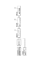
図2は、図1の車両運転傾向判定装置による判定結果を用いる無段変速機の変速制御システム(本発明による車両動作応答制御装置の一実施例)である。
Hereinafter, embodiments of the present invention will be described in detail based on examples shown in the drawings.
FIG. 1 shows a vehicle driving tendency (sporty driving tendency and luxury driving tendency) determination device including a vehicle travel path curve tendency detecting device according to an embodiment of the present invention.
FIG. 2 is a transmission control system for a continuously variable transmission (one embodiment of the vehicle operation response control apparatus according to the present invention) that uses the determination result by the vehicle driving tendency determination apparatus of FIG.
先ず図1の車両運転傾向判定装置を説明するに、この判定装置は、
車両の前後加速度Gxを検出する前後加速度センサ1からの信号と、
車速VSPを検出する車速センサ2からの信号と、
右車輪速VRを検出する右車輪速センサ3からの信号と、
左車輪速VLを検出する左車輪速センサ4からの信号と、
アクセルペダル踏み込み量(アクセル開度)APOを検出するアクセル開度センサ5からの信号を入力信号とし、
以下のようにして、運転者による車両の運転傾向(スポーティー運転傾向や、ラグジュアリ運転傾向)を判定する。
First, the vehicle driving tendency determination device in FIG. 1 will be described.
A signal from the
A signal from the
A signal from the right
A signal from the left wheel speed sensor 4 for detecting the left wheel speed VL,
The signal from the
The driving tendency of the vehicle by the driver (sporty driving tendency or luxury driving tendency) is determined as follows.
これがため図1の車両運転傾向判定装置は、運転者による車両の加減速操作傾向を検出する加減速傾向検出部10と、本発明の湾曲傾向検出装置に相当する湾曲傾向検出部20と、検出部10からの加減速傾向信号αおよび検出部20からの湾曲傾向信号βのうち大きい方を選択して運転状態信号γとするセレクトハイ・スイッチ30とより成る車両運転状態信号生成部40を具えるほか、
該生成部40からの運転状態信号γをフィルタリング処理して該信号γの平均出力レベルから運転傾向を判定する運転傾向判定部50と、
この判定部50で行うフィルタリング処理に際して用いる時定数を選択するための時定数選択部60とを具える。
Therefore, the vehicle driving tendency determination device of FIG. 1 includes an acceleration / deceleration
A driving
A time
加減速傾向検出部10は図3に示すごときもので、前後加速度Gxおよび車速VSPをもとに車両の加減速度合を検出して加減速傾向信号αを以下のように求める。
上記のGxが加速度(正値)である場合は、加速度基準値設定部11において予定のマップを基に車速VSPから、車両の可能最大加速度を加速度基準値Gaとして設定する。
次いで除算器12において、前後加速度Gxを加速度基準値Gaにより除算することにより、今の前後加速度Gxが最大加速度(加速度基準値)Gaに対してどの程度のものかを正規化(0〜1の信号に変換)した加速度正規化値αa=Gx/Gaを求める。
The acceleration / deceleration
When Gx is an acceleration (positive value), the acceleration reference value setting unit 11 sets the maximum possible acceleration of the vehicle as the acceleration reference value Ga from the vehicle speed VSP based on the planned map.
Next, in the
上記のGxが減速度(負値)である場合は、減速度基準値設定部13において予定のマップを基に車速VSPから、車両の可能最大減速度を減速度基準値Gbとして設定する。
次いで、減速度Gxを極性合わせのため極性反転器14により極性反転させ、除算器15において、減速度Gxの極性反転値を減速度基準値Gbにより除算することにより、今の減速度Gxが最大減速度(減速度基準値)Gbに対してどの程度のものかを正規化(0〜1の信号に変換)した減速度正規化値αb=|Gx|/Gbを求める。
この減速度正規化値αbを、加算器16で前記の加速度正規化値αaと合計して、両者の和値を、正規化した加減速傾向信号α=αa+αbとして図1のセレクトハイ・スイッチ30に供給する。
When Gx is a deceleration (negative value), the deceleration reference
Next, the polarity of the deceleration Gx is reversed by the
The deceleration normalization value αb is summed with the acceleration normalization value αa by the
図1における湾曲傾向検出部20は本発明における湾曲傾向検出装置に相当し、図4に示すごとく、横加速度演算部21と、バタワースフィルタ22と、横加速度微分値演算部23と、ローパスフィルタで構成した湾曲傾向算出部24とよりなり、該ローパスフィルタのフィルタ係数を設定するフィルタ係数設定部25を付加して構成する。
The bending
横加速度演算部21は、右車輪速VRおよび左車輪速VLから、図5につき以下に説明する理論に基づき車両に作用する横加速度Gyを算出するものである。
The lateral
先ず図5の理論を説明するに、図中、6Lは左車輪、6Rは右車輪である。
ここで、右車輪速VRおよび左車輪速VLの平均値Vwは、Vw=(VR+VL)/2で表され、これに車両旋回半径Rを乗算して得られる値は、右車輪速VRおよび左車輪速VL間の車輪速差(VR−VL)を左右輪間トレッドWで除算して得られる値に等しく、
{(VR+VL)/2}R=(VR−VL)/W
であり、この式から次式が得られる。
{(VR+VL)/(VR−VL)}W/2=R
ところで横加速度Gyは、Gy=Vw×2/Rであり、従って、横加速度Gyは、
Gy=Vw×2/R
=(VR−VL)・(VR+VL)}・(1/2)W
で表される。
First, the theory of FIG. 5 will be explained. In the figure, 6L is a left wheel and 6R is a right wheel.
Here, the average value Vw of the right wheel speed VR and the left wheel speed VL is expressed by Vw = (VR + VL) / 2, and the value obtained by multiplying this by the vehicle turning radius R is the right wheel speed VR and the left wheel speed VL. Equal to the value obtained by dividing the wheel speed difference (VR-VL) between the wheel speeds VL by the tread W between the left and right wheels,
{(VR + VL) / 2} R = (VR-VL) / W
From this equation, the following equation is obtained.
{(VR + VL) / (VR−VL)} W / 2 = R
By the way, the lateral acceleration Gy is Gy = Vw × 2 / R. Therefore, the lateral acceleration Gy is
Gy = Vw × 2 / R
= (VR-VL) ・ (VR + VL)} ・ (1/2) W
It is represented by
図4における横加速度演算部21は、右車輪速VRおよび左車輪速VLと、左右輪間トレッドWの半値とから、上式の演算により横加速度Gyを求める。
なお横加速度Gyは、かように演算により求めるのが経済的であるが、この代わりに、横加速度センサにより直接検出してもよいことは言うまでもない。
The lateral
It is economical to obtain the lateral acceleration Gy by such calculation, but it goes without saying that it may be directly detected by a lateral acceleration sensor instead.
上記の演算により求めた横加速度Gyはバタワースフィルタ22に通過させ、これにより、後述するごとく不整地走行などに伴う左右輪速差に起因して横加速度Gyの演算値に含まれる横加速度演算誤差を除去する。
図4における横加速度微分値演算部23は、かようにバタワースフィルタ22に通過させた後における横加速度(Gy)フィルタ処理値の時間変化割合である横加速度微分値dGyを求めて、その絶対値|dGy|を出力する。
従って横加速度微分値演算部23は、本発明における横加速度微分値演算手段に相当する。
The lateral acceleration Gy obtained by the above calculation is passed through the
The lateral acceleration differential value calculation unit 23 in FIG. 4 obtains the lateral acceleration differential value dGy, which is the rate of change over time of the lateral acceleration (Gy) filter processing value after passing through the
Accordingly, the lateral acceleration differential value calculation unit 23 corresponds to the lateral acceleration differential value calculation means in the present invention.
その後、かかる横加速度微分値|dGy|を湾曲傾向算出部24に通過させて車両走行路の湾曲傾向βを求める。
ここで湾曲傾向算出部24は、車速VSPが40km/hである場合について説明すると、図6に例示するごとく低い周波数領域で振幅ゲインが大きなフィルタゲイン特性を持ったローパスフィルタとし、走行状態に応じて異なる有効周波数帯の横加速度微分値|dGy|を抽出すると共にそれ以外の周波数帯におけるノイズ成分を除去し、当該ローパスフィルタを通過して抽出された横加速度微分値|dGy|の平均出力レベルから、前述したと同様にして0〜1の数値に正規化した車両走行路の湾曲傾向βを求める。
従って湾曲傾向算出部24はは、本発明における湾曲傾向推定手段に相当する。
Thereafter, the lateral acceleration differential value | dGy | is passed through the bending tendency calculation unit 24 to obtain the bending tendency β of the vehicle travel path.
Here, the bending tendency calculation unit 24 will explain the case where the vehicle speed VSP is 40 km / h. As illustrated in FIG. 6, the bending tendency calculation unit 24 is a low-pass filter having a filter gain characteristic with a large amplitude gain in a low frequency region, according to the traveling state. The differential output value | dGy | of different effective frequency bands is extracted, noise components in other frequency bands are removed, and the average output level of the differential value of lateral acceleration | dGy | extracted through the low-pass filter is extracted. In the same manner as described above, the curve tendency β of the vehicle traveling path normalized to a numerical value of 0 to 1 is obtained.
Therefore, the bending tendency calculation unit 24 corresponds to a bending tendency estimation unit in the present invention.
ところで、上記のように抽出すべき横加速度微分値|dGy|の有効周波数帯は、車速VSPなどの走行状態に応じて異なり、車速VSPが40km/hの時は横加速度微分値|dGy|が図7(a),(b)に波線(図6と同じもの)で示すごとく低周波数域で発生するが、車速VSPが80km/hの時は横加速度微分値|dGy|が図7(a),(b)に実線で示すごとく高周波数域で発生し、上記横加速度微分値|dGy|の有効周波数帯は車速VSPが高いほど高周波数域となる。 By the way, the effective frequency band of the lateral acceleration differential value | dGy | to be extracted as described above differs depending on the driving state such as the vehicle speed VSP, and when the vehicle speed VSP is 40 km / h, the lateral acceleration differential value | dGy | As shown by the wavy lines in Fig. 7 (a) and (b) (same as Fig. 6), it occurs in the low frequency range, but when the vehicle speed VSP is 80km / h, the lateral acceleration differential value | dGy | ) and (b) are generated in a high frequency range as indicated by a solid line, and the effective frequency band of the lateral acceleration differential value | dGy | becomes higher as the vehicle speed VSP is higher.
この事実から、図4に示すようにフィルタ係数設定部25を設け、これにより、湾曲傾向算出部24を成すローパスフィルタのフィルタ係数を、車速VSP(図5につき前述した車輪速平均値Vwでもよい)に応じ、高車速ほど高周波数域の横加速度微分値|dGy|を抽出し得るフィルタゲイン特性となるよう制御可能にする。
From this fact, a filter
従って、車速VSP=40km/hの時は、湾曲傾向算出部24を成すローパスフィルタのフィルタゲイン特性が図6および図7(a)に示すごときものとなって、車速VSP=40km/h時の有効周波数帯における横加速度微分値|dGy|を抽出すると共にそれ以外の周波数帯におけるノイズ成分を除去し得ることとなり、また、
車速VSP=80km/hの時は、湾曲傾向算出部24を成すローパスフィルタのフィルタゲイン特性が図7(b)に示すごときものとなって、車速VSP=80km/h時の有効周波数帯における横加速度微分値|dGy|を抽出すると共にそれ以外の周波数帯におけるノイズ成分を除去し得ることとなる。
Therefore, when the vehicle speed VSP is 40 km / h, the filter gain characteristics of the low-pass filter forming the bending tendency calculation unit 24 are as shown in FIGS. 6 and 7A, and when the vehicle speed VSP is 40 km / h. It is possible to extract the lateral acceleration differential value | dGy | in the effective frequency band and remove noise components in other frequency bands,
When the vehicle speed VSP = 80 km / h, the filter gain characteristics of the low-pass filter that forms the bending tendency calculation unit 24 are as shown in FIG. 7B, and the horizontal frequency in the effective frequency band when the vehicle speed VSP = 80 km / h is obtained. The acceleration differential value | dGy | can be extracted and noise components in other frequency bands can be removed.
なお、湾曲傾向算出部24を成すローパスフィルタとしては、車速VSPに応じて有効周波数帯が異なる横加速度微分値|dGy|を抽出できれば、上記の単一のローパスに限らず、図8に例示するようなフィルタゲイン特性を持ったバンドパスフィルタでもよいし、図9に例示するようなローパスフィルおよびハイパスフィルタの組み合わせにより構成してもよいことは言うまでもない。 Note that the low-pass filter that forms the bending tendency calculation unit 24 is not limited to the single low-pass described above, and is illustrated in FIG. 8 as long as the lateral acceleration differential value | dGy | having a different effective frequency band depending on the vehicle speed VSP can be extracted. Needless to say, a band-pass filter having such a filter gain characteristic may be used, or a combination of a low-pass filter and a high-pass filter exemplified in FIG.
図4における演算部21で前記のようにして演算した横加速度Gyをバタワースフィルタ22に通過させ、当該横加速度Gyの演算値に含まれる横加速度演算誤差を除去することによる効果を、図10に基づき以下に説明する。
図10(a)は、図4におけるバタワースフィルタ22が存在せず、横加速度演算値Gyをそのまま横加速度微分値演算部23に入力して横加速度微分値|dGy|の演算に資する場合における、直進走行時の動作タイムチャート、
図10(b)は、図4に示すようにバタワースフィルタ22を設け、横加速度演算値Gyをバタワースフィルタ22に通過させた後に横加速度微分値演算部23へ入力して横加速度微分値|dGy|の演算に資する場合における、直進走行時の動作タイムチャートである。
The effect of removing the lateral acceleration calculation error included in the calculated value of the lateral acceleration Gy by passing the lateral acceleration Gy calculated as described above by the calculating
FIG. 10 (a) shows the case where the
In FIG. 10 (b), a
図10(a),(b)に示すように、左右車輪速VL,VRがそれぞれ不整地などに起因して振動的に変化する場合(図では左右車輪速VL,VRの一方のみを示す)、両者の変動が同期せず位相ずれをもって変動することから、両者間の車輪速差(VL-VR)が直進走行時なのに図示のごとくに発生する。
このため、図4の演算部21で車輪速差(VL-VR)を用いて前記のごとくに演算した横加速度演算値Gyは、横加速度発生原因でないにもかかわらず、位相ずれをもって振動的に変化する左右車輪速VL,VR間の上記車輪速差(VL-VR)をも横加速度発生原因として内包し、図10(a),(b)に示すごときものとなる。
As shown in FIGS. 10 (a) and 10 (b), when the left and right wheel speeds VL and VR change in vibration due to rough terrain, etc. (only one of the left and right wheel speeds VL and VR is shown in the figure) Since the fluctuations of the two do not synchronize but fluctuate with a phase shift, the wheel speed difference (VL-VR) between the two occurs as shown in the figure even when traveling straight ahead.
For this reason, the lateral acceleration calculation value Gy calculated as described above using the wheel speed difference (VL-VR) in the
バタワースフィルタ22を設けない場合、図10(a)に示すように横加速度フィルタ処理値が横加速度演算値Gyと同じであり、これがそのまま図4の横加速度微分値演算部23に入力され、横加速度微分値|dGy|の演算に供される。
When the
よって横加速度微分値|dGy|が、不整地などのため位相ずれをもって振動的に変化する左右車輪速VL,VR間の上記車輪速差(VL-VR)に起因した演算値成分をも内包する横加速度演算値Gyに基づくものであることから、直進走行時なのに図10(a)に示すように大きくなる。
従って、この横加速度微分値|dGy|を基に図4の算出部24で前記のごとくに求める車両走行路の湾曲傾向βが、直進走行中であるにもかかわらず、図10(a)に示すように発生し、この湾曲傾向βから後述するように求める車両運転傾向δも、本来なら加減速傾向のみを持った波線で示すごときものであるところ、実線で示すように誤差を持ったものになる。
Therefore, the lateral acceleration differential value | dGy | also includes the calculated value component due to the wheel speed difference (VL-VR) between the left and right wheel speeds VL and VR, which changes vibrationally with a phase shift due to rough terrain. Since it is based on the lateral acceleration calculation value Gy, it becomes larger as shown in FIG.
Therefore, based on the lateral acceleration differential value | dGy |, the curve tendency β of the vehicle travel path obtained by the calculation unit 24 of FIG. 4 as described above is shown in FIG. The vehicle driving tendency δ, which is generated as shown below and is obtained from the curve tendency β, as will be described later, is originally a broken line having only an acceleration / deceleration tendency, but has an error as shown by a solid line. become.
これに対し図4のようにバタワースフィルタ22を設けた場合、図10(b)に示すように横加速度フィルタ処理値が、横加速度演算値Gyをバタワースフィルタ22に通過させて得られたもの、つまり、横加速度演算値Gyから、不整地などのため位相ずれをもって振動的に変化する左右車輪速VL,VR間の上記車輪速差(VL-VR)に起因した演算値成分を除去したものとなり、かかるフィルタ処理後の横加速度演算値Gyが図4の横加速度微分値演算部23に入力され、横加速度微分値|dGy|の演算に供される。
On the other hand, when the
よって横加速度微分値|dGy|が、不整地などのため位相ずれをもって振動的に変化する左右車輪速VL,VR間の上記車輪速差(VL-VR)に起因した演算値成分を含まない横加速度演算値Gyに基づくものとなり、横加速度微分値|dGy|が直進走行に符合して図10(b)に示すごとく略0に保たれる。
従って、この横加速度微分値|dGy|を基に図4の算出部24で前記のごとくに求める車両走行路の湾曲傾向βが、直進走行に符合して図10(b)に示すように0に保たれ、この湾曲傾向βから後述するように求める車両運転傾向δも、加減速傾向のみを持った図示するごとき誤差のないものになる。
Therefore, the lateral acceleration differential value | dGy | does not include the calculated value component caused by the wheel speed difference (VL-VR) between the left and right wheel speeds VL and VR, which changes vibrationally with a phase shift due to rough terrain. Based on the acceleration calculation value Gy, the lateral acceleration differential value | dGy | coincides with the straight traveling and is kept substantially zero as shown in FIG. 10 (b).
Therefore, the curve tendency β of the vehicle travel path obtained as described above by the calculation unit 24 of FIG. 4 based on the lateral acceleration differential value | dGy | is 0 as shown in FIG. Therefore, the vehicle driving tendency δ obtained as described later from this bending tendency β also has no error as shown in the figure having only the acceleration / deceleration tendency.
図11は、図1における湾曲傾向検出部20の他の実施例で、図4におけると同様の部分を同一符号にて示す。
本実施例においては、バタワースフィルタ22に通過させた横加速度演算値Gyをそのまま横加速度微分値演算部23へ入力せず、横加速度補正ゲイン設定部26で設定した補正ゲインにより、特に低車速時において横加速度演算値Gyを小さくなるよう補正し、低車速時はこの補正した横加速度演算値Gyを横加速度微分値演算部23へ入力するようになす。
FIG. 11 shows another embodiment of the bending
In this embodiment, the lateral acceleration calculation value Gy passed through the
これがため横加速度補正ゲイン設定部26は、車速VSP(図5につき前述した車輪速平均値Vwでもよい)を基に予定のマップから、低車速で小さくなる横加速度補正ゲイン(1より小さな正値)を検索して設定し、これを乗算器27において、バタワースフィルタ22に通過させた横加速度演算値Gyに乗算し、低車速で小さくなる補正済横加速度演算値Gyを求める。
For this reason, the lateral acceleration correction gain setting unit 26 calculates a lateral acceleration correction gain (a positive value smaller than 1) that becomes smaller at a low vehicle speed from a planned map based on the vehicle speed VSP (may be the wheel speed average value Vw described above with reference to FIG. 5). The
従って、横加速度微分値演算部23が補正済横加速度演算値Gyから前記したごとくに求める横加速度微分値|dGy|は、車速VSP=10km/h時について述べると、横加速度演算値Gyを補正しない場合の図12(a)に示す大きな値に対し、同図(b)に示すごとき小さなものとなり、低車速時に横加速度微分値|dGy|のピークを抑制することができる。
かようにすることにより、湾曲傾向算出部24が横加速度微分値|dGy|から前記したごとくに求める湾曲傾向βは低車速ほど小さくなって、これを用いた後述する車両の動作応答制御が低車速では行われないようにすることができる。
ちなみに、同じ湾曲傾向βを持った湾曲路でも、低車速では高車速時のような車両の動作応答制御が不要であり、このような時に不要な車両の動作応答制御がなされる愚を避けることができる。
Accordingly, the lateral acceleration differential value | dGy | obtained as described above from the corrected lateral acceleration calculated value Gy by the lateral acceleration differential value calculation unit 23 corrects the lateral acceleration calculated value Gy when the vehicle speed VSP = 10 km / h is described. In contrast, the large value shown in FIG. 12 (a) is smaller as shown in FIG. 12 (b), and the peak of the lateral acceleration differential value | dGy | can be suppressed at low vehicle speeds.
By doing so, the bending tendency β obtained by the bending tendency calculation unit 24 as described above from the lateral acceleration differential value | dGy | becomes smaller as the vehicle speed becomes lower, and the motion response control of the vehicle described later using this becomes lower. It can be prevented from being done at vehicle speed.
By the way, even on curved roads with the same curve tendency β, it is not necessary to control vehicle response at high vehicle speeds at low vehicle speeds, and avoid the foolishness of unnecessary vehicle response control at such times. Can do.
ところで、上記した各実施例による湾曲傾向の検出方式においては、車両の横加速度Gyに基づき車両走行路の湾曲傾向βを検出するに当たり、この横加速度Gyをそのまま用いず、その時間変化割合である車両横加速度微分値|dGy|を基に湾曲傾向βの検出を行うため、以下の作用効果が得られる。
図13は、車両走行イメージにより示すように車両が直進路を走行している間における、前記横加速度演算値Gy、横加速度微分値|dGy|、および湾曲傾向βの経時変化を示し、この図から明らかなように直進路走行のため、横加速度演算値Gyは継続的に0であり、横加速度微分値|dGy|も継続的に0であり、横加速度微分値|dGy|を基に0〜1の値に正規化して求めた湾曲傾向βも当然0に保たれる。
By the way, in the detection method of the bending tendency according to each of the above-described embodiments, when detecting the bending tendency β of the vehicle travel path based on the lateral acceleration Gy of the vehicle, the lateral acceleration Gy is not used as it is, and the time change rate is obtained. Since the bending tendency β is detected based on the vehicle lateral acceleration differential value | dGy |, the following effects are obtained.
FIG. 13 shows temporal changes of the lateral acceleration calculation value Gy, the lateral acceleration differential value | dGy |, and the bending tendency β while the vehicle is traveling on a straight path as shown by the vehicle traveling image. As can be seen from the figure, the lateral acceleration calculation value Gy is continuously 0, the lateral acceleration differential value | dGy | is also 0 continuously, and 0 based on the lateral acceleration differential value | dGy | Naturally, the bending tendency β obtained by normalizing to a value of ˜1 is also kept at 0.
図14は、車両走行イメージにより示すように車両が湾曲路を走行している間における、前記横加速度演算値Gy、横加速度微分値|dGy|、および湾曲傾向βの経時変化を示し、この図から明らかなように湾曲路走行のため、横加速度演算値Gyは湾曲路の湾曲状況に応じた0を基準とするサイン波形となり、その時間変化割合である横加速度微分値|dGy|は図示のごとく正値を保って連続的に変化するサイン波形となり、この横加速度微分値|dGy|の平均出力レベルを前述したと同様に0〜1の値に正規化して求めた湾曲傾向βは、横加速度微分値|dGy|の振幅および変化頻度に応じたレベルとなり、このレベルが高いほど車両走行路の湾曲傾向が強い(湾曲変化頻度が高い)と判定することができる。 FIG. 14 shows temporal changes of the lateral acceleration calculation value Gy, the lateral acceleration differential value | dGy |, and the bending tendency β while the vehicle is traveling on a curved road as shown by the vehicle traveling image. As can be seen from the figure, because of running on a curved road, the lateral acceleration calculation value Gy is a sine waveform based on 0 according to the curved condition of the curved road, and the lateral acceleration differential value | dGy | As shown above, the curve tendency β obtained by normalizing the average output level of the lateral acceleration differential value | dGy | to a value of 0 to 1 is It becomes a level according to the amplitude and change frequency of the acceleration differential value | dGy |, and it can be determined that the higher the level is, the stronger the tendency of the vehicle traveling path to bend (the higher the curve change frequency).
図15は、左右輪間でタイヤ摩耗や空気圧が異なったり、左右輪の一方がパンクするなどして、左右輪タイヤ有効径の異なる異径タイヤ車両が、車両走行イメージにより示すように直進路を走行している間における、前記横加速度演算値Gy、横加速度微分値|dGy|、および湾曲傾向βの経時変化を示す。
この場合、図15から明らかなように直進路走行とはいえ、左右輪タイヤ有効径が異なることに起因して横加速度演算値Gyは0でなくなり、左右輪タイヤ有効径の差(左右車輪速差)に応じた横加速度分の値となる。
しかし、左右輪タイヤ有効径が異なることで発生する左右車輪速差は一定であり、横加速度演算値Gyも図15に示すように一定値である。
よって横加速度微分値|dGy|は継続的に0に保たれ、横加速度微分値|dGy|を基に0〜1の値に正規化して求めた湾曲傾向βも当然0に保たれる。
従って、左右輪タイヤ有効径が異なったことで横加速度演算値Gyが発生しても、これが走行路湾曲傾向βの検出に影響せず、左右輪タイヤ有効径が異なった時に湾曲傾向βが誤検出されるのを防止することができる。
FIG. 15 shows that different tire tires with different effective diameters on the left and right wheels have a straight path as shown by the vehicle running image due to differences in tire wear and air pressure between the left and right wheels, or puncture of one of the left and right wheels. Changes in the lateral acceleration calculation value Gy, the lateral acceleration differential value | dGy |, and the bending tendency β over time during traveling are shown.
In this case, as is apparent from FIG. 15, although the vehicle travels on a straight road, the lateral acceleration calculation value Gy is not 0 due to the difference in the effective diameters of the left and right wheel tires. It is the value for the lateral acceleration corresponding to the difference.
However, the difference between the left and right wheel speeds generated when the left and right wheel tire effective diameters are different is constant, and the lateral acceleration calculation value Gy is also a constant value as shown in FIG.
Therefore, the lateral acceleration differential value | dGy | is continuously kept at 0, and the bending tendency β obtained by normalizing to 0 to 1 based on the lateral acceleration differential value | dGy | is naturally kept at 0.
Therefore, even if the lateral acceleration calculation value Gy occurs due to the difference in the effective diameters of the left and right wheel tires, this does not affect the detection of the traveling road curve tendency β. It can be prevented from being detected.
図16は、左右輪タイヤ有効径の異なる異径タイヤ車両が、車両走行イメージにより示すように湾曲路を走行している間における、前記横加速度演算値Gy、横加速度微分値|dGy|、および湾曲傾向βの経時変化を示す。
この場合、図16から明らかなように湾曲路走行のため、横加速度演算値Gyは湾曲路の湾曲状況に応じたサイン波形となるが、この波形が、波線で示す左右同径タイヤ時における横加速度演算値Gyのサイン波形(図14におけると同じ)よりも、左右輪タイヤ有効径の差(左右車輪速差)に応じた横加速度分の値だけ図示のごとくに嵩上げされたものとなる。
しかし同じ湾曲傾向であれば、横加速度演算値Gyのサイン波形は、左右同径タイヤである場合の波形(波線図示)も、左右異径タイヤである場合の波形(実線図示)も、同じ形となり、その時間変化割合である横加速度微分値|dGy|は図示のごとく、図14におけると同様な、正値を保った連続的に変化するサイン波形となり、この横加速度微分値|dGy|の平均出力レベルを0〜1の値に正規化して求めた湾曲傾向βも図14におけると同様なものとなる。
従って、左右輪タイヤ有効径が異なったことで横加速度演算値Gyが左右輪タイヤ有効径の差(左右車輪速差)に応じた横加速度分の値だけ嵩上げされても、この嵩上げ分が走行路湾曲傾向βの検出に影響せず、左右輪タイヤ有効径が異なった時に湾曲傾向βが誤検出されるのを防止することができる。
FIG. 16 shows that the lateral acceleration calculated value Gy, the lateral acceleration differential value | dGy |, and different tire tire vehicles having different effective diameters of the left and right wheel tires are traveling on a curved road as shown by the vehicle traveling image, and The time-dependent change of the bending tendency β is shown.
In this case, as is apparent from FIG. 16, because the vehicle runs on a curved road, the lateral acceleration calculation value Gy becomes a sine waveform corresponding to the curved condition of the curved road. Rather than the sine waveform of the acceleration calculation value Gy (same as in FIG. 14), the value corresponding to the lateral acceleration corresponding to the difference in the effective diameter of the left and right tires (the difference between the left and right wheel speeds) is raised as shown in the figure.
However, if the curve tendency is the same, the sine waveform of the lateral acceleration calculation value Gy has the same shape for both the left and right tires with the same diameter (the wavy line) and the waveform with the right and left tires with different diameters (the solid line). As shown in the figure, the lateral acceleration differential value | dGy |, which is the rate of change over time, is a continuously changing sine waveform that maintains a positive value, as in FIG. 14, and the lateral acceleration differential value | dGy | The bending tendency β obtained by normalizing the average output level to a value of 0 to 1 is the same as that in FIG.
Accordingly, even if the lateral acceleration calculated value Gy is increased by a value corresponding to the lateral acceleration corresponding to the difference between the left and right tire effective diameters (the difference in the left and right wheel speeds) due to the difference in the effective diameters of the left and right tires, the increased amount is increased. It is possible to prevent the curve tendency β from being erroneously detected when the effective diameters of the left and right wheel tires are different without affecting the detection of the road curve tendency β.
図1のセレクトハイ・スイッチ30は、検出部10で前記のごとくに検出した車両の加減速傾向信号α(0〜1間の正規化した値)、および、検出部20で前記各実施例につき前述したごとくに検出した車両走行路の湾曲傾向信号β(0〜1間の正規化した値)のうち、大きい方MAX(α,β)を運転状態信号γ(0〜1間の正規化した値)として出力する。
セレクトハイ・スイッチ30から(車両運転状態信号生成部40から)の運転状態信号γ=MAX(α,β)は運転傾向判定部50に入力し、この運転傾向判定部50は運転状態信号γをフィルタリング処理して該信号γの平均出力レベルから0〜1間の値に正規化した運転傾向δ(スポーティー運転傾向、ラグジュアリー運転傾向)を判定する。
The select
The driving state signal γ = MAX (α, β) from the select high switch 30 (from the vehicle driving state signal generation unit 40) is input to the driving
なお、運転傾向判定部50で行う運転状態信号γのフィルタリング処理に際して用いる時定数は、時定数選択部60が前後加速度Gxと、車速VSPと、アクセル開度APOとから判る車両の運転状態に応じて定め、あらゆる運転状態で運転傾向δ(スポーティー運転傾向、ラグジュアリー運転傾向)の判定を確実、且つ、正確に行い得るようになすものとする。
The time constant used in the filtering process of the driving state signal γ performed by the driving
図1による運転傾向δの検出処理を、左右車輪速VL,VRがそれぞれ図17に示すごときものである場合につき説明するに、
左右車輪速VL,VR間における車輪速差(VR-VL)を基に横加速度演算部21(図4参照)で前記したごとくに演算される横加速度演算値Gy、
これを図4のバタワースフィルタ22に通過させた後の横加速度フィルタ処理値、
これを基に横加速度微分値演算部23(図4参照)で前記したごとくに演算される横加速度微分値|dGy|、および、
これを基に湾曲傾向算出部24(図4参照)で前記したごとくに演算される路面湾曲傾向(横加速度変化頻度)βはそれぞれ図17に示すように経時変化する。
The detection process of the driving tendency δ according to FIG. 1 will be described in the case where the left and right wheel speeds VL and VR are respectively as shown in FIG.
Lateral acceleration calculation value Gy calculated as described above in the lateral acceleration calculation unit 21 (see FIG. 4) based on the wheel speed difference (VR-VL) between the left and right wheel speeds VL and VR,
Lateral acceleration filter processing value after passing this through the
Based on this, the lateral acceleration differential value | dGy | calculated as described above in the lateral acceleration differential value calculation unit 23 (see FIG. 4), and
Based on this, the road curve tendency (lateral acceleration change frequency) β calculated as described above by the curve tendency calculation unit 24 (see FIG. 4) changes with time as shown in FIG.
ところで図1による運転傾向δの検出処理が、検出部10からの加減速傾向信号α(0〜1間の正規化した値)と、検出部20からの湾曲傾向信号β(0〜1間の正規化した値)との大きい方を運転状態信号γとし、運転傾向δの演算に資することから、以下の作用効果を奏し得る。
つまり、加減速傾向信号αのみを用いて運転傾向δの演算を行うと、湾曲路であっても加減速傾向信号αがそれほど大きくない運転を行う場合、運転傾向δは図17の最下段に波線で示すように小さなものとなって、湾曲路であるにもかかわらずラグジュアリー運転傾向と判定する。
これに対し図1による運転傾向δの検出処理によれば、加減速傾向信号α(0〜1間の正規化した値)と、湾曲傾向信号β(0〜1間の正規化した値)との大きい方を運転状態信号γとし、運転傾向δの演算に資するため、湾曲路なのに加減速傾向信号αが大きくならない運転を行ったとしても、運転傾向δは湾曲路相応の湾曲傾向βに呼応して、図17の最下段に実線で示すように大きなものとなり、湾曲路では確実にこれに応じたスポーティー運転傾向と判定することができる。
By the way, the detection process of the driving tendency δ according to FIG. 1 is performed by the acceleration / deceleration tendency signal α (a normalized value between 0 and 1) from the detecting
In other words, when the driving tendency δ is calculated using only the acceleration / deceleration tendency signal α, the driving tendency δ is at the lowest level in FIG. It becomes small as shown by the wavy line, and it is judged as a luxury driving tendency even though it is a curved road.
On the other hand, according to the detection process of the driving tendency δ according to FIG. 1, the acceleration / deceleration tendency signal α (a normalized value between 0 and 1) and the bending tendency signal β (a normalized value between 0 and 1) In order to contribute to the calculation of driving tendency δ, the driving state signal γ corresponds to the bending tendency β corresponding to the curved road even if the acceleration / deceleration tendency signal α is not increased. Then, it becomes large as shown by the solid line in the lowermost stage of FIG. 17, and it can be determined that the sporty driving tendency according to this is sure on the curved road.
図1の運転傾向判定装置をマイクロコンピュータで構成する場合、その制御プログラムは図18や、図19に示すごときものとなり、図18は、図1における湾曲傾向検出部20が図4に示すようなものである場合の運転傾向判定プログラム、図19は、図1における湾曲傾向検出部20が図11に示すようなものである場合の運転傾向判定プログラムである。
When the driving tendency determination device of FIG. 1 is configured with a microcomputer, the control program is as shown in FIG. 18 or FIG. 19, and FIG. 18 shows the curve
先ず図18の運転傾向判定プログラムを説明するに、
ステップS11において、左右車輪速VL,VRを読み込み、
ステップS12において、図4の演算部21で行ったと同様な処理により横加速度Gyを演算する。
次いでステップS13において、横加速度演算値Gyに内包されるノイズを図4のバタワースフィルタ22によると同様なフィルタ処理により除去し、
ステップS14において、図4の演算部23で行ったと同様な処理により横加速度Gyの時間変化割合である横加速度微分値|dGy|を演算する。
First, to explain the driving tendency judgment program of FIG.
In step S11, the left and right wheel speeds VL and VR are read,
In step S12, the lateral acceleration Gy is calculated by a process similar to that performed by the
Next, in step S13, noise included in the lateral acceleration calculation value Gy is removed by the same filter processing as the
In step S14, the lateral acceleration differential value | dGy |, which is the time change rate of the lateral acceleration Gy, is calculated by the same processing as that performed by the calculation unit 23 of FIG.
ステップS15においては、図4の算出部24で行ったと同様な処理により横加速度微分値|dGy|から湾曲傾向(湾曲変化頻度)βを求め、
ステップS16において、この湾曲傾向(湾曲変化頻度)βを前述したと同様の処理により0〜1の数値に正規化し、
ステップS17においては、図4の検出部10(詳細は図3参照)で行ったと同様な処理により前後加速度Gxおよび車速VSPから、0〜1の数値に正規化された加減速傾向αを算出する。
In step S15, a bending tendency (bending change frequency) β is obtained from the lateral acceleration differential value | dGy | by the same process as that performed by the calculation unit 24 of FIG.
In step S16, this bending tendency (bending change frequency) β is normalized to a numerical value of 0 to 1 by the same process as described above,
In step S17, the acceleration / deceleration tendency α normalized to a numerical value of 0 to 1 is calculated from the longitudinal acceleration Gx and the vehicle speed VSP by the same processing as that performed by the
次のステップS18においては、ともに正規化された加減速傾向αと湾曲傾向(湾曲変化頻度)βとを比較し、
α<βであればステップS19において、大きい方の湾曲傾向(湾曲変化頻度)βに基づき、図1の判定部50で行ったと同様な処理により運転傾向δを求め、
α>βであればステップS20において、大きい方の加減速傾向αに基づき、図1の判定部50で行ったと同様な処理により運転傾向δを求める。
In the next step S18, both the acceleration / deceleration tendency α normalized and the bending tendency (curving change frequency) β are compared,
If α <β, in step S19, based on the larger curve tendency (curve change frequency) β, the driving tendency δ is obtained by the same process as that performed by the
If α> β, in step S20, based on the larger acceleration / deceleration tendency α, the driving tendency δ is obtained by the same process as that performed by the
次に図19の運転傾向判定プログラムを説明するに、これは、図18のステップS13およびステップS14間にステップS21を追加したものである。
追加したステップS21においては、ステップS13で図11のバタワースフィルタ22によると同様なフィルタ処理によりノイズ除去した後の横加速度演算値Gyを、図11の横加速度補正ゲイン設定部26および乗算器27によると同様な処理により、低車速ほど小さくなるよう補正し、
ステップS14で前記したごとくに横加速度微分値|dGy|を演算するに当たっては、当該補正した横加速度演算値Gyを用い、これにより、低車速では横加速度微分値|dGy|のピークを図12(b)につき前述したごとくに抑制する。
Next, the driving tendency determination program of FIG. 19 will be described, which is obtained by adding step S21 between step S13 and step S14 of FIG.
In the added step S21, the lateral acceleration calculation value Gy after noise removal by the same filter processing as in the
In calculating the lateral acceleration differential value | dGy | in step S14 as described above, the corrected lateral acceleration calculated value Gy is used, and as a result, the peak of the lateral acceleration differential value | dGy | Suppress as described above for b).
前記各実施例のようにして求めた車両の運転傾向β(スポーティー運転傾向や、ラグジュアリ運転傾向)は、例えば図2に示すように無段変速機の変速制御に用いて、車両の動作応答制御に供することができる。
図2において、71は、無段変速機の目標入力回転数Niを表した変速制御マップを示し、72は、無段変速機のスポーティ運転時における目標入力回転数の下限値NLim(Sporty)を表したスポーティ運転時目標入力回転数下限値マップを示し、73は、無段変速機のラグジュアリー運転時における目標入力回転数の下限値NLim(Luxuary)を表したラグジュアリー運転時目標入力回転数下限値マップを示す。
The vehicle driving tendency β (sporty driving tendency and luxury driving tendency) obtained as in each of the above embodiments is used for shift control of a continuously variable transmission, for example, as shown in FIG. Can be used.
In FIG. 2, 71 represents a shift control map representing the target input rotational speed Ni of the continuously variable transmission, and 72 represents the lower limit NLim (Sporty) of the target input rotational speed during sporty operation of the continuously variable transmission. The sporty driving target input speed lower limit map is shown. 73 is the luxury target driving input speed lower limit value NLim (Luxuary) representing the lower limit of the target input speed during luxury driving of the continuously variable transmission. Show the map.
変速制御マップ71は、アクセル開度APOおよび車速VSPをもとに、現在の運転状態に最適な無段変速機の目標入力回転数Niを検索し、
スポーティ運転時目標入力回転数下限値マップ72は、無段変速機のスポーティ運転時における比較的高い目標入力回転数の下限値NLim(Sporty)を車速VSPごとに求め、
ラグジュアリー運転時目標入力回転数下限値マップ73は、無段変速機のラグジュアリー運転時における比較的低い(変速制御マップ71のハイ側目標入力回転数に同じ)目標入力回転数の下限値NLim(Luxuary)を車速VSPごとに求める。
Based on the accelerator opening APO and the vehicle speed VSP, the
The target input rotation speed
The target input speed
補間計算部74は、前記した運転傾向δ(スポーティー運転傾向と、ラグジュアリー運転傾向との間の値)に応じ、現在の運転傾向δおよび車速VSPのもとでは目標入力回転数の下限値NLimを、スポーティ運転時の目標入力回転数下限値NLim(Sporty)と、ラグジュアリー運転時の目標入力回転数下限値NLim(Luxuary)との間の如何なる値にすべきかを補間計算により求める。
セレクトハイ・スイッチ75では、変速制御マップ71からの目標入力回転数Niと、補間計算部74からの目標入力回転数下限値NLimとのうち大きい方を制限済み目標入力回転数Ni(Lim)として選択し、無段変速機の実入力回転数がこの制限済み目標入力回転数Ni(Lim)に一致するよう無段変速機を変速制御する。
The
In the select
運転傾向δ(スポーティー運転傾向と、ラグジュアリー運転傾向との間の値)に応じたかかる無段変速機の変速制御によれば、運転傾向δがスポーティー運転傾向であればあるほど、制限済み目標入力回転数Ni(Lim)がスポーティ運転時の比較的高い目標入力回転数下限値NLim(Sporty)に接近し、結果として無段変速機は入力回転数を高く保たれるロー側変速比選択傾向となり、運転者のアクセル操作に対する車両の動作応答を高めて、スポーティー運転時に好まれる車両の動作応答を実現することができる。 According to the speed change control of the continuously variable transmission according to the driving tendency δ (a value between the sporty driving tendency and the luxury driving tendency), the more the driving tendency δ is the sporty driving tendency, the more limited the target input. The rotational speed Ni (Lim) approaches the relatively high target input rotational speed lower limit value NLim (Sporty) during sporty operation, and as a result, the continuously variable transmission tends to select a low-side gear ratio that keeps the input rotational speed high. The vehicle operation response to the driver's accelerator operation can be improved, and the vehicle operation response preferred during sporty driving can be realized.
なお、運転傾向δに応じた車両の動作応答制御は、図2につき上述したような無段変速機の変速制御に限らず、図20に示すようなショックアブソーバの減衰力制御や、図21に示すローリング抑止用スタビライザの剛性切り替え制御や、図22に示すパワーステアリング用操舵シスト力制御とすることもできる。 Note that the vehicle operation response control according to the driving tendency δ is not limited to the speed change control of the continuously variable transmission as described above with reference to FIG. 2, but the shock absorber damping force control as shown in FIG. It is also possible to adopt the rigidity switching control of the rolling suppression stabilizer shown in FIG. 22 or the steering steering force control for power steering shown in FIG.
図20に示すショックアブソーバの減衰力制御にあっては、ショックアブソーバコントローラ76が基本的には車速VSPやブレーキスイッチ信号などの車両情報に応じてショックアブソーバの目標減衰力を決定し、ショックアブソーバの減衰力がこの目標に一致するようモータや油圧ソレノイドなどの駆動装置77を介してショックアブソーバの減衰力調整オリフィス78を開度制御するが、
運転傾向δ(スポーティー運転傾向と、ラグジュアリー運転傾向との間の値)に応じ、運転傾向δがスポーティー運転傾向であればあるほど、上記の目標減衰力を大きくして減衰力調整オリフィス78の開度を小さくすることにより、
運転者のステアリング操作に対する車両の挙動応答を高めて、スポーティー運転時に好まれる車両の動作応答を実現することができる。
In the shock absorber damping force control shown in FIG. 20, the
Depending on the driving tendency δ (a value between a sporty driving tendency and a luxury driving tendency), the more the driving tendency δ is a sporty driving tendency, the larger the target damping force described above and the opening of the damping
It is possible to increase the vehicle behavior response to the driver's steering operation, and to realize the vehicle operation response that is preferred during sporty driving.
図21に示すローリング抑止用スタビライザの剛性切り替え制御にあっては、スタビライザコントローラ79が基本的には車速VSPや操舵角θなどの車両情報に応じてスタビライザの目標剛性を決定し、スタビライザの剛性がこの目標に一致するようモータや油圧ソレノイドなどの駆動装置80を介してスタビライザの剛性切り替え機構91を作動させるが、
運転傾向δ(スポーティー運転傾向と、ラグジュアリー運転傾向との間の値)に応じ、運転傾向δがスポーティー運転傾向であればあるほど、上記の目標剛性を大きくしてスタビライザの剛性を大きくすることにより、
運転者のステアリング操作時に車両がローリングするのを抑制して、スポーティー運転時に好まれる車両の動作応答を実現することができる。
In the stiffness switching control of the rolling suppression stabilizer shown in FIG. 21, the
Depending on the driving tendency δ (the value between the sporty driving tendency and the luxury driving tendency), the more the driving tendency δ is the sporty driving tendency, the larger the target rigidity and the higher the rigidity of the stabilizer. ,
It is possible to suppress the rolling of the vehicle at the time of the steering operation by the driver, and to realize the operation response of the vehicle that is preferred during the sporty driving.
図22に示すパワーステアリングの操舵シスト力制御にあっては、パワーステアリングコントローラ92が基本的には車速VSPや操舵角θなどの車両情報に応じてパワーステアリングの目標アシスト力を決定し、パワーステアリングのアシスト力がこの目標に一致するようモータや油圧ソレノイドなどの駆動装置93を介してパワーステアリングのアシスト機構94を作動させるが、
運転傾向δ(スポーティー運転傾向と、ラグジュアリー運転傾向との間の値)に応じ、運転傾向δがスポーティー運転傾向であればあるほど、上記の目標アシスト力を小さくして操舵力を重くすることにより、
スポーティー運転時に好まれる安定した操舵特性と、車両の動作応答を実現することができる。
In the power steering steering force control shown in FIG. 22, the
Depending on the driving tendency δ (a value between a sporty driving tendency and a luxury driving tendency), the more the driving tendency δ is a sporty driving tendency, the smaller the target assist force and the higher the steering force. ,
Stable steering characteristics preferred during sporty driving and vehicle response can be achieved.
1 前後加速度センサ
2 車速センサ
3 右車輪速センサ
4 左車輪速センサ
5 アクセル開度センサ
10 加減速傾向検出部
11 加速度基準値設定部
12 除算器
13 減速度基準値設定部
14 極性反転器
20 湾曲傾向検出部(湾曲傾向検出装置)
21 横加速度演算部
22 バタワースフィルタ
23 横加速度微分値演算部(横加速度微分値演算手段)
24 湾曲傾向算出部(湾曲傾向推定手段:フィルタ手段)
25 フィルタ係数設定部
26 横加速度補正ゲイン設定部
27 乗算器
30 セレクトハイ・スイッチ
40 車両運転状態信号生成部
50 運転傾向判定部
60 時定数選択部
71 変速制御マップ
72 スポーティ運転時目標入力回転数下限値マップ
73 ラグジュアリー運転時目標入力回転数下限値マップ
74 補間計算部
75 セレクトハイ・スイッチ
1 Longitudinal acceleration sensor
2 Vehicle speed sensor
3 Right wheel speed sensor
4 Left wheel speed sensor
5 Accelerator position sensor
10 Acceleration / deceleration trend detector
11 Acceleration reference value setting section
12 Divider
13 Deceleration reference value setting section
14 Polarity inverter
20 Bending tendency detector (bending tendency detector)
21 Lateral acceleration calculator
22 Butterworth filter
23 Lateral acceleration differential value calculation section (lateral acceleration differential value calculation means)
24 Bending tendency calculation unit (bending tendency estimation means: filter means)
25 Filter coefficient setting section
26 Lateral acceleration compensation gain setting section
27 multiplier
30 Select high switch
40 Vehicle operation state signal generator
50 Driving tendency judgment part
60 Time constant selector
71 Shift control map
72 Target input speed lower limit map for sporty operation
73 Lower limit target input speed map for luxury driving
74 Interpolation calculator
75 Select high switch
Claims (5)
右車輪速及び左車輪速から前記横加速度を求める横加速度演算手段と、
左右輪速差に起因して前記横加速度の演算値に含まれる横加速度演算誤差を除去するバタワースフィルタと、
演算誤差除去後の横加速度から、前記横加速度の時間変化割合である横加速度微分値を求めるための横加速度微分値演算手段と、
車速に応じてフィルタ係数が設定されるフィルタで構成され、前記横加速度微分値をもとに前記車両走行路の湾曲傾向を推定する湾曲傾向推定手段と
を具備してなることを特徴とする車両走行路の湾曲傾向検出装置。 In an apparatus for detecting a curve tendency of a vehicle travel path based on a lateral acceleration in a vehicle width direction acting on a vehicle,
Lateral acceleration calculating means for obtaining the lateral acceleration from the right wheel speed and the left wheel speed;
A Butterworth filter for removing a lateral acceleration calculation error included in the calculated value of the lateral acceleration due to a difference between left and right wheel speeds;
From the lateral acceleration after the operation error is removed, and the lateral acceleration differential value calculating means for calculating a lateral acceleration differential value Ru time change rate der before Kiyoko acceleration,
A vehicle, comprising: a filter whose filter coefficient is set in accordance with a vehicle speed; and a bending tendency estimating means for estimating a bending tendency of the vehicle travel path based on the lateral acceleration differential value. A device for detecting a tendency to bend a traveling path.
前記湾曲傾向推定手段は、低い周波数領域で振幅ゲインが大きなフィルタゲイン特性を持ったローパスフィルタで構成され、車速に応じて有効周波数帯が異なる横加速度微分値を抽出し、抽出された前記横加速度微分値の平均出力レベルから前記車両走行路の湾曲傾向を推定することを特徴とする車両走行路の湾曲傾向検出装置。 The vehicle travel path bending tendency detection device according to claim 1,
The bending tendency estimation means is lower in the frequency domain is composed of a low pass filter the amplitude gain with a large filter gain characteristics, the lateral acceleration enable frequency band extracting different lateral acceleration differential value in accordance with the vehicle speed, the extracted bending tendency detection device for a vehicle traveling path, wherein the benzalkonium to estimate the curvature trend of the vehicle traveling road from the average output level of the differential value.
前記ローパスフィルタは、前記有効周波数帯を高車速であるほど高周波数帯とするものであることを特徴とする車両走行路の湾曲傾向検出装置。 The vehicle travel path bending tendency detection device according to claim 2,
The low-pass filter, the bending tendency detection device for a vehicle travel path, characterized in that the effective frequency band is for the higher frequency band to be a high speed.
前記横加速度微分値演算手段は、低車速時、補正ゲインにより小さくなるよう補正した前記横加速度の演算値が入力することにより、低車速であるほど前記車両横加速度微分値のピークを抑制して前記湾曲傾向を小さくするものであることを特徴とする車両走行路の湾曲傾向検出装置。 The bending tendency detection device for a vehicle travel path according to any one of claims 1 to 3,
The lateral acceleration differential value calculation means, at low speed, by the calculating value of the lateral acceleration corrected to be smaller by the correction gain is input, to suppress the peak of the vehicle lateral acceleration differential value as is a low vehicle speed A bending tendency detecting device for a vehicle traveling path, which reduces the bending tendency.
前記運転状態信号をフィルタリング処理して前記運転状態信号の平均出力レベルから運転傾向を判定する運転傾向判定手段とを有し、
検出した車両走行路の湾曲傾向に基づき、前記湾曲傾向が強いほど、運転者の運転操作に対する車両の動作応答が速くなるよう車両状態を制御することを特徴とする車両の動作応答制御装置。 An acceleration / deceleration trend signal by detecting the vehicle acceleration / deceleration rate based on the curve tendency signal of the vehicle travel path detected by the curve tendency detection device according to any one of claims 1 to 4, and the longitudinal acceleration and the vehicle speed. Driving state signal generating means for selecting the larger one of the acceleration / deceleration tendency signals from the acceleration / deceleration tendency detecting means to obtain an operating state signal;
Driving tendency determination means for filtering the driving state signal and determining a driving tendency from an average output level of the driving state signal;
Based on the curvature trend of the detected vehicle running path, the higher the bending tendency is strong, the operation response control device for a vehicle according to claim and Turkey to control the vehicle state such that the operational response of the vehicle becomes faster with respect to the driving operation of the driver .
Priority Applications (5)
| Application Number | Priority Date | Filing Date | Title |
|---|---|---|---|
| JP2006071354A JP4640224B2 (en) | 2006-03-15 | 2006-03-15 | VEHICLE TRAVEL BENDING DETECTING DEVICE AND VEHICLE ACTION RESPONSE |
| US11/684,838 US7957877B2 (en) | 2006-03-15 | 2007-03-12 | Curving tendency detection device in vehicle, and vehicle response control apparatus using same |
| CN2007100056670A CN101038181B (en) | 2006-03-15 | 2007-03-13 | Curving tendency detection device in vehicle, and vehicle response control apparatus using same |
| EP07104229A EP1834816B1 (en) | 2006-03-15 | 2007-03-15 | Curving Tendency Detection |
| DE602007002426T DE602007002426D1 (en) | 2006-03-15 | 2007-03-15 | Curving tendency detection |
Applications Claiming Priority (1)
| Application Number | Priority Date | Filing Date | Title |
|---|---|---|---|
| JP2006071354A JP4640224B2 (en) | 2006-03-15 | 2006-03-15 | VEHICLE TRAVEL BENDING DETECTING DEVICE AND VEHICLE ACTION RESPONSE |
Publications (2)
| Publication Number | Publication Date |
|---|---|
| JP2007245897A JP2007245897A (en) | 2007-09-27 |
| JP4640224B2 true JP4640224B2 (en) | 2011-03-02 |
Family
ID=38134137
Family Applications (1)
| Application Number | Title | Priority Date | Filing Date |
|---|---|---|---|
| JP2006071354A Expired - Fee Related JP4640224B2 (en) | 2006-03-15 | 2006-03-15 | VEHICLE TRAVEL BENDING DETECTING DEVICE AND VEHICLE ACTION RESPONSE |
Country Status (5)
| Country | Link |
|---|---|
| US (1) | US7957877B2 (en) |
| EP (1) | EP1834816B1 (en) |
| JP (1) | JP4640224B2 (en) |
| CN (1) | CN101038181B (en) |
| DE (1) | DE602007002426D1 (en) |
Families Citing this family (28)
| Publication number | Priority date | Publication date | Assignee | Title |
|---|---|---|---|---|
| FR2885555B1 (en) * | 2005-05-10 | 2011-04-15 | Renault Sas | METHOD FOR CONTROLLING AT LEAST ONE ANTI-ROLLER BAR ACTUATOR ON BOARD A VEHICLE |
| DE102005054141A1 (en) * | 2005-11-14 | 2007-05-16 | Bosch Gmbh Robert | Method for determining the tire diameter of a motor vehicle |
| JP4640224B2 (en) * | 2006-03-15 | 2011-03-02 | 日産自動車株式会社 | VEHICLE TRAVEL BENDING DETECTING DEVICE AND VEHICLE ACTION RESPONSE |
| US8744689B2 (en) * | 2007-07-26 | 2014-06-03 | Hitachi, Ltd. | Drive controlling apparatus for a vehicle |
| JP5061776B2 (en) * | 2007-08-03 | 2012-10-31 | 日産自動車株式会社 | Vehicle travel control device and vehicle travel control method |
| JP5116702B2 (en) * | 2009-01-20 | 2013-01-09 | 富士重工業株式会社 | Shift control device for automatic transmission |
| JP4873042B2 (en) * | 2009-04-13 | 2012-02-08 | トヨタ自動車株式会社 | Vehicle control apparatus and vehicle control method |
| DE112009005022B4 (en) * | 2009-07-02 | 2013-09-26 | Mitsubishi Electric Corporation | Body speed estimator and collision safety guard system |
| DE112010003322B4 (en) | 2009-08-18 | 2020-01-02 | Toyota Jidosha Kabushiki Kaisha | Vehicle control system |
| JP5447290B2 (en) * | 2009-08-18 | 2014-03-19 | トヨタ自動車株式会社 | Vehicle control device |
| IT1398073B1 (en) * | 2010-02-19 | 2013-02-07 | Teleparking S R L | SYSTEM AND ESTIMATE METHOD OF THE DRIVING STYLE OF A MOTOR VEHICLE |
| EP2762372A1 (en) * | 2011-09-27 | 2014-08-06 | Toyota Jidosha Kabushiki Kaisha | Vehicle drive force control apparatus |
| US9550480B2 (en) | 2011-10-21 | 2017-01-24 | Autoliv Nissin Brake Systems Japan Co., Ltd. | Vehicle brake hydraulic pressure control apparatus and road surface friction coefficient estimating device |
| JP5892245B2 (en) * | 2012-06-13 | 2016-03-23 | 日産自動車株式会社 | Vehicle driving force control device and driving force control method |
| CN103939599B (en) * | 2014-04-29 | 2016-10-05 | 长城汽车股份有限公司 | A kind of automatic transmission shift control method, Apparatus and system |
| KR101575277B1 (en) * | 2014-08-11 | 2015-12-07 | 현대자동차 주식회사 | Apparatus and method of determining driving tendency of driver |
| CN104653766B (en) * | 2015-03-23 | 2017-01-04 | 上海汽车变速器有限公司 | The shift control method of vehicle bend and system |
| CA2986881C (en) * | 2015-05-22 | 2019-01-22 | Nissan Motor Co., Ltd. | Failure diagnosis device and failure diagnosis method |
| US9889878B2 (en) * | 2015-12-14 | 2018-02-13 | GM Global Technology Operations LLC | Method of tuning a calibration table for an electric power steering system, and a calibration system therefore |
| JP2018008550A (en) * | 2016-07-11 | 2018-01-18 | 株式会社デンソー | Steering control device |
| KR101905568B1 (en) * | 2016-12-15 | 2018-10-08 | 현대자동차 주식회사 | Apparatus for controlling cornering of vehicle and method thereof |
| CN107192560A (en) * | 2017-05-17 | 2017-09-22 | 重庆长安汽车股份有限公司 | A kind of vehicle accelerates power method for objectively evaluating |
| CN107842604A (en) * | 2017-09-20 | 2018-03-27 | 中国第汽车股份有限公司 | The method that Vehicular turn parameter is calculated using acceleration transducer |
| CN110274589B (en) * | 2018-03-15 | 2021-07-30 | 阿里巴巴(中国)有限公司 | Positioning method and device |
| CN111267853B (en) * | 2018-12-03 | 2021-06-18 | 广州汽车集团股份有限公司 | A kind of adaptive vehicle curve assist control method, device, computer equipment and storage medium |
| JP7135929B2 (en) * | 2019-02-20 | 2022-09-13 | トヨタ自動車株式会社 | Braking force controller |
| WO2021231758A1 (en) * | 2020-05-15 | 2021-11-18 | ClearMotion, Inc. | System and method for estimating lateral acceleration |
| DE112021003647T5 (en) * | 2020-07-08 | 2023-06-29 | Hitachi Astemo, Ltd. | Vehicle control device and suspension system |
Family Cites Families (42)
| Publication number | Priority date | Publication date | Assignee | Title |
|---|---|---|---|---|
| JP2528781Y2 (en) | 1988-12-26 | 1997-03-12 | 株式会社 ユニシアジェックス | Suspension system |
| DE3922040A1 (en) | 1989-07-05 | 1991-01-17 | Porsche Ag | METHOD AND DEVICE FOR CONTROLLING AN AUTOMATIC GEARBOX |
| DE3922051A1 (en) * | 1989-07-05 | 1991-01-24 | Porsche Ag | METHOD AND DEVICE FOR CONTROLLING AN AUTOMATIC GEARBOX |
| DE3924691C2 (en) * | 1989-07-26 | 1993-11-04 | Daimler Benz Ag | METHOD FOR COMPENSATING ERRORS OF AN ACCELERATOR |
| JP2623927B2 (en) * | 1990-07-05 | 1997-06-25 | 日産自動車株式会社 | Vehicle turning behavior control device |
| US5668724A (en) * | 1990-09-28 | 1997-09-16 | Robert Bosch Gmbh | Method for improving the controllabilty of motor vehicles |
| JP3015514B2 (en) | 1991-06-26 | 2000-03-06 | ナルデック株式会社 | Vehicle suspension device |
| JP3282256B2 (en) * | 1992-12-24 | 2002-05-13 | ティーディーケイ株式会社 | Supporting mechanism for floating magnetic head and magnetic head device |
| JPH07215193A (en) | 1994-01-31 | 1995-08-15 | Toyota Motor Corp | Vehicle behavior abnormality detection device |
| JP3116738B2 (en) * | 1994-07-28 | 2000-12-11 | トヨタ自動車株式会社 | Vehicle behavior control device |
| JPH0848257A (en) | 1994-08-09 | 1996-02-20 | Mitsubishi Motors Corp | Power steering controller |
| JP3305518B2 (en) | 1994-11-22 | 2002-07-22 | 本田技研工業株式会社 | Vehicle control device |
| US5735584A (en) * | 1994-11-25 | 1998-04-07 | Itt Automotive Europe Gmbh | Process for driving stability control with control via pressure gradients |
| DE19515057B4 (en) * | 1994-11-25 | 2006-08-03 | Continental Teves Ag & Co. Ohg | Brake system for a motor vehicle |
| US5711024A (en) * | 1994-11-25 | 1998-01-20 | Itt Automotive Europe Gmbh | System for controlling yaw moment based on an estimated coefficient of friction |
| US5710705A (en) * | 1994-11-25 | 1998-01-20 | Itt Automotive Europe Gmbh | Method for determining an additional yawing moment based on side slip angle velocity |
| US5671143A (en) * | 1994-11-25 | 1997-09-23 | Itt Automotive Europe Gmbh | Driving stability controller with coefficient of friction dependent limitation of the reference yaw rate |
| US5710704A (en) * | 1994-11-25 | 1998-01-20 | Itt Automotive Europe Gmbh | System for driving stability control during travel through a curve |
| US5701248A (en) * | 1994-11-25 | 1997-12-23 | Itt Automotive Europe Gmbh | Process for controlling the driving stability with the king pin inclination difference as the controlled variable |
| US5694321A (en) * | 1994-11-25 | 1997-12-02 | Itt Automotive Europe Gmbh | System for integrated driving stability control |
| US5774821A (en) * | 1994-11-25 | 1998-06-30 | Itt Automotive Europe Gmbh | System for driving stability control |
| DE19615311B4 (en) * | 1996-04-18 | 2006-06-29 | Robert Bosch Gmbh | Method and device for controlling a movement quantity representing the vehicle movement |
| DE19628980A1 (en) * | 1996-07-18 | 1998-01-22 | Teves Gmbh Alfred | Process for improving the control behavior of an ABS in the curve |
| DE19703322C1 (en) * | 1997-01-30 | 1998-03-26 | Abb Daimler Benz Transp | Carriage body inclination control module for rail vehicle |
| JP3428620B2 (en) | 1997-12-29 | 2003-07-22 | 三菱自動車工業株式会社 | Road surface friction coefficient determination device |
| SE511258C2 (en) * | 1998-01-27 | 1999-09-06 | Abb Daimler Benz Transp | Device for estimating lateral acceleration of a rail vehicle |
| US5948028A (en) * | 1998-02-03 | 1999-09-07 | Ford Global Technologies, Inc. | Method of improving response time in a vehicle active tilt control system |
| JP4320827B2 (en) | 1998-03-20 | 2009-08-26 | 株式会社デンソー | Body behavior control device |
| JPH11268647A (en) * | 1998-03-23 | 1999-10-05 | Tokico Ltd | Vibration control device for railway vehicles |
| JP3906399B2 (en) * | 1998-03-31 | 2007-04-18 | 株式会社日立製作所 | Suspension control device |
| US6625527B1 (en) * | 1999-02-18 | 2003-09-23 | Continental Teves Ag & Co. Ohg | Sensor system with monitoring device |
| JP2004500507A (en) * | 1999-12-03 | 2004-01-08 | ロベルト・ボッシュ・ゲゼルシャフト・ミト・ベシュレンクテル・ハフツング | Method for adjusting output torque of driving engine of automobile and running dynamic characteristic control device |
| SE519932C2 (en) * | 2000-05-25 | 2003-04-29 | Bombardier Transp Gmbh | Method and apparatus for determining a parameter for a tracked vehicle |
| DE10054647A1 (en) * | 2000-11-03 | 2002-05-08 | Daimler Chrysler Ag | Procedure for regulating driving stability |
| DE10291454D2 (en) * | 2001-03-28 | 2004-04-29 | Continental Teves Ag & Co Ohg | Process for improving the control behavior and the thermal load capacity of a motor vehicle control system |
| DE10130663A1 (en) * | 2001-06-28 | 2003-01-23 | Continental Teves Ag & Co Ohg | Method for modifying a driving stability control of a vehicle |
| WO2004041612A1 (en) * | 2002-11-08 | 2004-05-21 | Continental Teves Ag & Co.Ohg | Method and system for stabilizing a vehicle combination |
| JP2004347032A (en) | 2003-05-22 | 2004-12-09 | Fuji Heavy Ind Ltd | Transmission control device for transmission |
| JP2005125894A (en) * | 2003-10-22 | 2005-05-19 | Nissan Motor Co Ltd | Vehicle speed control device |
| CN100408398C (en) * | 2003-10-28 | 2008-08-06 | 大陆-特韦斯贸易合伙股份公司及两合公司 | Method and system for improving driving performance of vehicle |
| JP5034222B2 (en) * | 2005-11-17 | 2012-09-26 | トヨタ自動車株式会社 | Vehicle driving force control device |
| JP4640224B2 (en) * | 2006-03-15 | 2011-03-02 | 日産自動車株式会社 | VEHICLE TRAVEL BENDING DETECTING DEVICE AND VEHICLE ACTION RESPONSE |
-
2006
- 2006-03-15 JP JP2006071354A patent/JP4640224B2/en not_active Expired - Fee Related
-
2007
- 2007-03-12 US US11/684,838 patent/US7957877B2/en not_active Expired - Fee Related
- 2007-03-13 CN CN2007100056670A patent/CN101038181B/en not_active Expired - Fee Related
- 2007-03-15 EP EP07104229A patent/EP1834816B1/en not_active Not-in-force
- 2007-03-15 DE DE602007002426T patent/DE602007002426D1/en active Active
Also Published As
| Publication number | Publication date |
|---|---|
| EP1834816A1 (en) | 2007-09-19 |
| CN101038181A (en) | 2007-09-19 |
| CN101038181B (en) | 2010-06-09 |
| US20070219700A1 (en) | 2007-09-20 |
| JP2007245897A (en) | 2007-09-27 |
| US7957877B2 (en) | 2011-06-07 |
| EP1834816B1 (en) | 2009-09-16 |
| DE602007002426D1 (en) | 2009-10-29 |
Similar Documents
| Publication | Publication Date | Title |
|---|---|---|
| JP4640224B2 (en) | VEHICLE TRAVEL BENDING DETECTING DEVICE AND VEHICLE ACTION RESPONSE | |
| RU2497692C2 (en) | Vehicle suspension adaptive control | |
| US9375990B2 (en) | Suspension control device | |
| JP5234224B1 (en) | Vehicle control device | |
| JP3800901B2 (en) | Lane tracking control device | |
| KR102673012B1 (en) | System and method for determining backlash of driving system in vehicle | |
| KR102067216B1 (en) | Method and device for detecting a situation in which a motor vehicle is driving over a poor road surface | |
| JP2015214321A (en) | Stability control system, saddle-riding type vehicle having stability control system, method and computer program | |
| JP5908022B2 (en) | Measurement data acquisition system, saddle-ride type vehicle equipped with measurement data acquisition system, method and computer program | |
| JP5447290B2 (en) | Vehicle control device | |
| JP6000430B2 (en) | Measurement data acquisition system, saddle-ride type vehicle equipped with measurement data acquisition system, method and computer program | |
| US20140343815A1 (en) | Vehicle control system | |
| JP2010023803A (en) | Device and method for controlling vehicle | |
| JPH06227228A (en) | Suspension control device | |
| JP4212131B2 (en) | Method and apparatus for generating acceleration signal | |
| CN111824254B (en) | Steering control method and system for vehicle | |
| JP6238369B2 (en) | Vehicle suspension control device | |
| JP2024518686A (en) | Method for determining slip limits of vehicle wheels - Patents.com | |
| US11840210B2 (en) | Vehicle control system | |
| KR100229413B1 (en) | Rolling control system and control method of a vehicle | |
| JPH1178466A (en) | Damping force control device and road surface estimation method | |
| JP2006145517A (en) | Evaluation method of steering characteristics | |
| JP3334572B2 (en) | Damping force control device and road surface estimation method | |
| JPH1178468A (en) | Damping force control device and road surface estimation method | |
| US20250121878A1 (en) | Apparatus and Method of Compensating an Oscillation in a Steering System Without a Mechanical Connection Between the Control Unit and the Steered Wheels |
Legal Events
| Date | Code | Title | Description |
|---|---|---|---|
| A621 | Written request for application examination |
Free format text: JAPANESE INTERMEDIATE CODE: A621 Effective date: 20090204 |
|
| A871 | Explanation of circumstances concerning accelerated examination |
Free format text: JAPANESE INTERMEDIATE CODE: A871 Effective date: 20100720 |
|
| A975 | Report on accelerated examination |
Free format text: JAPANESE INTERMEDIATE CODE: A971005 Effective date: 20100805 |
|
| A131 | Notification of reasons for refusal |
Free format text: JAPANESE INTERMEDIATE CODE: A131 Effective date: 20100817 |
|
| A521 | Request for written amendment filed |
Free format text: JAPANESE INTERMEDIATE CODE: A523 Effective date: 20101018 |
|
| RD03 | Notification of appointment of power of attorney |
Free format text: JAPANESE INTERMEDIATE CODE: A7423 Effective date: 20101018 |
|
| TRDD | Decision of grant or rejection written | ||
| A01 | Written decision to grant a patent or to grant a registration (utility model) |
Free format text: JAPANESE INTERMEDIATE CODE: A01 Effective date: 20101102 |
|
| A01 | Written decision to grant a patent or to grant a registration (utility model) |
Free format text: JAPANESE INTERMEDIATE CODE: A01 |
|
| A61 | First payment of annual fees (during grant procedure) |
Free format text: JAPANESE INTERMEDIATE CODE: A61 Effective date: 20101115 |
|
| R150 | Certificate of patent or registration of utility model |
Free format text: JAPANESE INTERMEDIATE CODE: R150 |
|
| FPAY | Renewal fee payment (event date is renewal date of database) |
Free format text: PAYMENT UNTIL: 20131210 Year of fee payment: 3 |
|
| LAPS | Cancellation because of no payment of annual fees |