JP4613370B2 - Non-aqueous electrolyte battery - Google Patents
Non-aqueous electrolyte battery Download PDFInfo
- Publication number
- JP4613370B2 JP4613370B2 JP30308398A JP30308398A JP4613370B2 JP 4613370 B2 JP4613370 B2 JP 4613370B2 JP 30308398 A JP30308398 A JP 30308398A JP 30308398 A JP30308398 A JP 30308398A JP 4613370 B2 JP4613370 B2 JP 4613370B2
- Authority
- JP
- Japan
- Prior art keywords
- hexafluoropropylene
- positive electrode
- vinylidene fluoride
- active material
- negative electrode
- Prior art date
- Legal status (The legal status is an assumption and is not a legal conclusion. Google has not performed a legal analysis and makes no representation as to the accuracy of the status listed.)
- Expired - Fee Related
Links
Images


Classifications
-
- Y—GENERAL TAGGING OF NEW TECHNOLOGICAL DEVELOPMENTS; GENERAL TAGGING OF CROSS-SECTIONAL TECHNOLOGIES SPANNING OVER SEVERAL SECTIONS OF THE IPC; TECHNICAL SUBJECTS COVERED BY FORMER USPC CROSS-REFERENCE ART COLLECTIONS [XRACs] AND DIGESTS
- Y02—TECHNOLOGIES OR APPLICATIONS FOR MITIGATION OR ADAPTATION AGAINST CLIMATE CHANGE
- Y02E—REDUCTION OF GREENHOUSE GAS [GHG] EMISSIONS, RELATED TO ENERGY GENERATION, TRANSMISSION OR DISTRIBUTION
- Y02E60/00—Enabling technologies; Technologies with a potential or indirect contribution to GHG emissions mitigation
- Y02E60/10—Energy storage using batteries
Landscapes
- Secondary Cells (AREA)
- Battery Electrode And Active Subsutance (AREA)
Description
【0001】
【発明の属する技術分野】
本発明は、非水電解液あるいは固体電解質、ゲル状電解質を用いた非水電解質電池に関するものであり、特に、結着剤の改良に関するものである。
【0002】
【従来の技術】
近年、カメラー体型VTR、携帯電話、携帯用コンピューター等のポータブル電子機器が多く登場し、その高性能が図られている。
【0003】
そして、これらの電子機器のポータブル電源として、電池、特に二次電池、なかでもリチウムイオン電池について多くの研究がなされている。
【0004】
例えば、より高性能な機器は電池に多大な負荷を要求するため、低負荷での使用時に比べてサイクル劣化が大きい。このため、より過酷な条件でもサイクル性能が維持できる電池が求められている。
【0005】
【発明が解決しようとする課題】
従来のポリビニリデンフルオロライド単体を結着剤として用いた電池は、高負荷でのサイクル時に電極、特に負極活物質層の集電体からの剥離により、容量劣化を引き起こす。
【0006】
この活物質層の剥離は、充放電サイクルにおける活物質の膨張、収縮によって引き起こされる。
【0007】
本発明は、かかる従来のものの有する欠点を解消するために提案されたものであり、負極電極や正極電極における活物質層の剥離を防止することを目的とし、これにより過酷な条件でも優れたサイクル性能を発揮する非水電解質電池を提供することを目的とする。
【0008】
【課題を解決するための手段】
上述の目的を達成するために、本発明の非水電解質電池は、集電体と、上記集電体上に形成されたリチウムをドープ・脱ドープし得る活物質と結着剤とを含有する活物質層とからなる正極電極及び負極電極を有し、上記正極電極及び/又は負極電極の結着剤は、ビニリデンフルオライドとヘキサフルオロプロピレンとの共重合体及びポリビニリデンフルオライドを含有し、上記ビニリデンフルオライドとヘキサフルオロプロピレンとの共重合体の結着剤中に占める割合が50〜95重量%であり、上記ビニリデンフルオライドとヘキサフルオロプロピレンとの共重合体中の上記ヘキサフルオロプロピレンの割合が3〜15重量%である。
【0009】
結着剤に、ビニリデンフルオロライドとヘキサフルオロプロピレンの共重合体とポリビニリデンフルオライドとを併用することにより、ポリビニリデンフルオロライド単体を用いた場合に比べて集電体への接着強度が高くなり、その結果、高負荷でのサイクル特性が向上する。
【0010】
【発明の実施の形態】
以下、本発明の非水電解質電池の構成について、詳細に説明する。
【0011】
本発明の非水電解質電池は、集電体と、上記集電体上に形成され活物質と結着剤とを含有する活物質層とからなる正極電極及び負極電極を有してなるものである。
【0012】
そして、これら正極電極、負極電極のいずれか一方、あるいは両方の結着剤としてビニリデンフルオライドとヘキサフルオロプロピレンとの共重合体(コポリマー)及びポリビニリデンフルオライドを用いることが大きな特徴である。
【0013】
ここで、結着剤中のコポリマーの割合は、30〜95重量%とすることが好ましい。コポリマーの割合が少なすぎると、十分な接着強度を確保することができない。また、逆にコポリマーの割合が多すぎても接着強度が低下する。これまで、コポリマーの割合が多いほど接着強度が上がると考えられてきたが、本発明者等の実験によれば、電解液を含む電池内では、コポリマーの割合が多すぎると却って接着強度が低下することがわかった。このような現象は、本発明者等によって初めて明らかにされたものである。
【0014】
また、コポリマーにおけるヘキサフルオロプロピレンの割合は、3〜30重量%未満とする。この範囲を外れると、やはり接着強度が低下する。
【0015】
本発明の電池は、上記のような結着剤を使用する以外は、従来のリチウムイオン電池と同様に構成することができる。
【0016】
すなわち、リチウムイオン電池を構成する場合の負極材料としては、リチウムをドープ、脱ドープできる材料を使用することができる。このような負極の構成材料、たとえば難黒鉛化炭素系材料や黒鉛系材料の炭素材料を使用することができる。より具体的には、熱分解炭素類、コークス類(ピッチコークス、ニードルコークス、石油コークス)、黒鉛類、ガラス状炭素類、有機高分子化合物焼成体(フェノール樹脂、フラン樹脂等を適当な温度で焼成し炭素化したもの)、炭素繊維、活性炭等の炭素材料を使用することができる。このほか、リチウムをドープ、脱ドープできる材料としては、ポリアセチレン、ポリピロール等の高分子やSnO2 等の酸化物を使用することもできる。このような材料から負極を形成するに際しては、公知の結着剤等を添加することができる。
【0017】
正極は、目的とする電池の種類に応じて、金属酸化物、金属硫化物または特定の高分子を正極活物質として用いて構成することができる。たとえばリチウムイオン電池を構成する場合、正極活物質としては、TiS2、MoS2、NbSe2,V2O5等のリチウムを含有しない金属硫化物あるいは酸化物や、LiMO2 (式中Mは一種以上の遷移金属を表し、xは電池の充放電状態によって異なり、通常0.05以上1.10以下である。)を主体とするリチウム複合酸化物等を使用することができる。このリチウム複合酸化物を構成する遷移金属Mとしては、Co,Ni,Mn等が好ましい。このようなリチウム複合酸化物の具体例としてはLiCoO2,LiNiO2,LiNiyCo1-yO2(式中、0<y<1である。)、LiMn2O4等を挙げることができる。これらリチウム複合酸化物は、高電圧を発生でき、エネルギー密度的に的に優れた正極活物質となる。正極には、これらの正極活物質の複数種をあわせて使用してもよい。また、以上のような正極活物質を使用して正極を形成するに際して、公知の導電剤や結着剤等を添加することができる。
【0018】
電解質は、非水電解液あるいは固体電解質、ゲル状電解質のいずれであってもよい。
【0019】
例えば固体電解質電池、またはゲル状電解質電池を考えた場合、高分子固体電解質に使用する高分子材料としては、シリコンゲル、アクリルゲル、アクリロニトリルゲル、ポリフォスファゼン変成ポリマー、ポリエチレンオキサイド、ポリプロピレンオキサイド、及びこれらの複合ポリマーや架橋ポリマー、変成ポリマーなどもしくはフッ素系ポリマーとして、たとえばポリ(ビニリデンフルオロライド)やポリ(ビニリデンフルオロライド-co-ヘキサフルオロプロピレン)、ポリ(ビニリデンフルオロライド-co-テトラフルオロエチレン)、ポリ(ビニリデンフルオロライド-co-トリフルオロエチレン)などおよびこれらの混合物が各種使用できるが、勿論、これらに限定されるものではない。
【0020】
正極活物質層または負極活物質層に積層されている固体電解質、またはゲル状電解質は、高分子化合物と電解質塩と溶媒、(ゲル電解質の場合は、さらに可塑剤)からなる溶液を正極活物質層または負極活物質層に含浸させ、溶媒を除去し固体化したものである。正極活物質層または負極活物質層に積層された固体電解質、またはゲル状電解質は、その一部が正極活物質層または負極活物質層に含浸されて固体化されている。架橋系の場合は、その後、光または熱で架橋して固体化される。
【0021】
ゲル状電解質は、リチウム塩を含む可塑剤と2重量%以上〜30重量%以下のマトリクス高分子からなる。このとき、エステル類、エーテル類、炭酸エステル類などを単独または可塑剤の一成分として用いることができる。
【0022】
ゲル状電解質を調整するにあたり、このような炭酸エステル類をゲル化するマトリクス高分子としては、ゲル状電解質を構成するのに使用されている種々の高分子が利用できるが、酸化還元安定性から、たとえばポリ(ビニリデンフルオロライド)やポリ(ビニリデンフルオロライド-co-ヘキサフルオロプロピレン)などのフッ素系高分子を用いることが望ましい。
【0023】
高分子固体電解質は、リチウム塩とそれを溶解する高分子化合物からなり、高分子化合物としては、ポリ(エチレンオキサイド)や同架橋体などのエーテル系高分子、ポリ(メタクリレート)エステル系、アクリレート系、ポリ(ビニリデンフルオロライド)やポリ(ビニリデンフルオロライド-co-ヘキサフルオロプロピレン)などのフッ素系高分子などを単独、または混合して用いることができるが、酸化還元安定性から、たとえばポリ(ビニリデンフルオロライド)やポリ(ビニリデンフルオロライド-co-ヘキサフルオロプロピレン)などのフッ素系高分子を用いることが望ましい。
【0024】
このようなゲル状電解質または高分子固体電解質に含有させるリチウム塩として通常の電池電解液に用いられるリチウム塩を使用することができ、リチウム化合物(塩)としては、例えば以下のものが挙げられるが、これらに限定されるものではない。
【0025】
たとえば、塩化リチウム臭化リチウム、ヨウ化リチウム、塩素酸リチウム、過塩素酸リチウム、臭素酸リチウム、ヨウ素酸リチウム、硝酸リチウム、テトラフルオロほう酸リチウム、ヘキサフルオロリン酸リチウム、酢酸リチウム、ビス(トリフルオロメタンスルフォニル)イミドリチウム、LiAsF6、LiCF3SO3、LiC(SO2CF3)3、LiAlCl4、LiSiF6等を挙げることができる。
【0026】
これらリチウム化合物は単独で用いても複数を混合して用いても良いが、これらの中でLiPF6、LiBF4が酸化安定性の点から望ましい。
【0027】
リチウム塩を溶解する濃度として、ゲル状電解質なら、可塑剤中に0.1〜3.0モルで実施できるが、好ましくは0.5から2.0モル/リットルで用いることができる。
【0028】
上記構成の非水電解質電池においては、電池形状についても特に限定されることはない。例えば、円筒型、角型、コイン型、ボタン型等、任意の形状とすることができ、薄型、大型等、サイズも任意に設定すればよい。
【0029】
【実施例】
次に、本発明を適用した具体的な実施例及び比較例について、実験結果に基づいて説明する。
【0030】
実施例1
先ず、負極を次のように作製した。
【0031】
粉砕した黒鉛粉末90重量部と、結着剤としてポリ(ビニリデンフルオロライド-co-ヘキサフルオロプロピレン)(ヘキサフルオロプロピレンの含有量:7重量%)10重量部とを混合して負極合剤を調製し、さらにこれをN−メチル−2−ピロリドンに分散させスラリー状とした。そして、このスラリーを負極集電体である厚さ10μmの帯状銅箔の片面に均一に塗布し、乾燥後、ロールプレス機で圧縮成形し、負極を作製した。
【0032】
一方、正極を次のように作製した。
【0033】
正極活物質(LiCoO2)を得るために、炭酸リチウムと炭酸コバルトを0.5モル対1モルの比率で混合し、空気中、900℃で5時間焼成した。次に、得られたLiCoO2 85重量部、導電剤として黒鉛5重量部、結着剤としてポリビニリデンフルオロライド10重量部とを混合して正極合剤を調製し、さらにこれをN−メチル−2−ピロリドンに分散させスラリー状とした。そして、このスラリーを正極集電体である厚さ20μmの帯状アルミニウム箔の片面に均一に塗布し、乾燥した後、ロールプレス機で圧縮成形し、正極を作製した。
【0034】
以上のようにして得られた正極、負極を厚さ25μmの微孔性ポリボロピレンフィルムからなるセパレーターを介して密着させ、炭酸プロピレン50容量%、ジメトキシエタン50容量%を混合した混合溶媒中に、6フッ化リン酸リチウムを1mol/lの割合で溶解させた電解液を注入し、サンプル電池を作製した。
【0035】
実施例2〜24
負極中、正極中の結着剤を表1のようにして作製した以外は、実施例1と同様に電池を作製した。なお、コポリマーの割合が30重量%のもの、及びヘキサフルオロプロピレンの含有量が30重量%であるものを参考例とした。
【0036】
実施例25
先ず、負極を次のように作製した。
【0037】
粉砕した黒鉛粉末90重量部と、結着剤としてポリ(ビニリデンフルオロライド-co-ヘキサフルオロプロピレン)(ヘキサフルオロプロピレンの含有量:7重量%)10重量部とを混合して負極合剤を調製し、さらにこれをN−メチル−2−ピロリドンに分散させスラリー状とした。そして、このスラリーを負極集電体である厚さ10μmの帯状銅箔の片面に均一に塗布し、乾燥後、ロールプレス機で圧縮成形し、負極を作製した。
【0038】
一方、正極を次のように作製した。
【0039】
正極活物質(LiCoO2)を得るために、炭酸リチウムと炭酸コバルトを0.5モル対1モルの比率で混合し、空気中、900℃で5時間焼成した。次に、得られたLiCoO2 85重量部、導電剤として黒鉛5重量部、結着剤としてポリビニリデンフルオロライド10重量部とを混合して正極合剤を調製し、さらにこれをN−メチル−2−ピロリドンに分散させスラリー状とした。そして、このスラリーを正極集電体である厚さ20μmの帯状アルミニウム箔の片面に均一に塗布し、乾燥した後、ロールプレス機で圧縮成形し、正極を作製した。
【0040】
さらに、ゲル状電解質を次のようにして得た。
【0041】
負極、正極上に炭酸エチレン(EC)42.5重量部、炭酸プロピレン(PC)42.5重量部、LiPF6 15重量部からなる可塑剤30重量部に、ポリ(ビニリデンフルオロライド-co-ヘキサフルオロプロピレン)(ヘキサフルオロプロピレンの含有量:7重量%)10重量部、そして炭酸ジエチル60重量部を混合溶解させた溶液を均一に塗布し、含浸させ、常温で8時間放置し、炭酸ジメチルを気化、除去しゲル状電解質を得た。
【0042】
ゲル状電解質を塗布した負極、及び正極をゲル状電解質側をあわせ、圧着することで平板型ゲル状電解質電池を作製した。
【0043】
実施例26〜48
負極中、正極中の結着剤を表2のようにして作製した以外は、実施例25と同様に電池を作製した。なお、コポリマーの割合が30重量%のもの、及びヘキサフルオロプロピレンの含有量が30重量%であるものを参考例とした。
【0044】
比較例1〜9
負極中、正極中の結着剤を表1のようにして作製した以外は、実施例1と同様に電池を作製した。
【0045】
比較例10〜18
負極中、正極中の結着剤を表2のようにして作製した以外は、実施例25と同様に電池を作製した。
【0046】
評価
各実施例、比較例で用いた正極、負極の活物質層の集電体への接着強度測定を行い、次のように評価した。
【0047】
短冊状に切り取った電極に粘着テープを貼り、集電体と活物質層を一部剥離させ、引っ張り試験機で180°に引っ張り、そのときの応力から接着強度を算出した。
【0048】
また、実施例1〜48及び比較例1〜18の電池について、理論容量の1時間率充放電(1C)を行い、次のように評価した。
【0049】
各電池に対して、23℃、5時間率(O.2C)の定電流定電圧充電を上限4.2Vまで15時間行い、次にO.2Cの定電流放電を終止電圧2.5V間で行なった。放電容量はこのように決定し、これを100%としたときの1時間率充放電(1C)500サイクル後の容量維持率を計算した。
【0050】
これらの測定結果を表1、表2及び図1、図2に示す。
【0051】
【表1】
【表2】
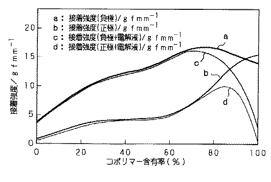
図1、図2から明らかなように、ポリ(ビニリデンフルオロライド−co−ヘキサフルオロプロピレン)を単独、または混合した電極の集電体への接着強度は向上しているのがわかった。
【0054】
その効果がポリ(ビニリデンフルオロライド−co−ヘキサフルオロプロピレン)中のヘキサフルオロプロピレンが3重量%から30重量%未満のとき、顕著な効果を示した。
【0055】
ポリ(ビニリデンフルオロライド−co−ヘキサフルオロプロピレン)とポリビニリデンフルオロライドを混合する場合、ポリ(ビニリデンフルオロライド−co−ヘキサフルオロプロピレン)が30重量%以上で顕著な効果が見られ、それは95重量%まで持続した。
【0056】
また、表1、表2から明らかなように、負極または正極にポリ(ビニリデンフルオロライド−co−ヘキサフルオロプロピレン)とポリビニリデンフルオロライドとを混合した結着剤を用いた場合、ポリビニリデンフルオロライドのみのものに比べて、明らかに500サイクル後の維持率が良かった。その効果は負極に用いたときに大きかった。また、ポリ(ビニリデンフルオロライド−co−ヘキサフルオロプロピレン)中のヘキサフルオロプロピレンが3重量%から30重量%のとき、顕著な効果を示し、接着強度と相関性があった。
【0057】
ポリ(ビニリデンフルオロライド−co−ヘキサフルオロプロピレン)とポリビニリデンフルオロライドを混合する場合、ポリ(ビニリデンフルオロライド−co−ヘキサフルオロプロピレン)が30重量%以上で顕著な効果が見られ、それは95重量%まで持続し、やはり接着強度と相関性があった。
【0058】
なお、非水電解液電池、ゲル状電解質電池共に同様の傾向が得られた。
【0059】
【発明の効果】
以上の説明からも明らかなように、本発明によれば、負極電極や正極電極における活物質層の剥離を防止することができ、過酷な条件でも優れたサイクル性能を発揮する非水電解質電池を提供することができる。
【図面の簡単な説明】
【図1】ヘキサフルオロプロピレンの含有率と接着強度の関係を示す特性図である。
【図2】コポリマーの含有率と接着強度の関係を示す特性図である。[0001]
BACKGROUND OF THE INVENTION
The present invention relates to a non-aqueous electrolyte battery using a non-aqueous electrolyte, a solid electrolyte, or a gel electrolyte, and particularly relates to improvement of a binder.
[0002]
[Prior art]
In recent years, many portable electronic devices such as camera-type VTRs, mobile phones, and portable computers have appeared and their high performance has been achieved.
[0003]
As a portable power source for these electronic devices, many studies have been made on batteries, in particular, secondary batteries, especially lithium ion batteries.
[0004]
For example, since a higher performance device requires a large load on the battery, the cycle deterioration is larger than that at the time of use at a low load. For this reason, a battery capable of maintaining cycle performance even under more severe conditions is demanded.
[0005]
[Problems to be solved by the invention]
A battery using a conventional polyvinylidene fluoride single substance as a binder causes capacity deterioration due to peeling of an electrode, particularly a negative electrode active material layer, from a current collector during a cycle under a high load.
[0006]
The separation of the active material layer is caused by the expansion and contraction of the active material in the charge / discharge cycle.
[0007]
The present invention has been proposed in order to eliminate the disadvantages of such conventional ones, and aims to prevent the active material layer from peeling off at the negative electrode or the positive electrode, thereby providing an excellent cycle even under severe conditions. It aims at providing the nonaqueous electrolyte battery which exhibits performance.
[0008]
[Means for Solving the Problems]
In order to achieve the above-described object, the nonaqueous electrolyte battery of the present invention contains a current collector, an active material capable of doping and dedoping lithium formed on the current collector, and a binder. It has a positive electrode and a negative electrode made of an active material layer, and the binder of the positive electrode and / or the negative electrode contains a copolymer of vinylidene fluoride and hexafluoropropylene and polyvinylidene fluoride, The proportion of the copolymer of vinylidene fluoride and hexafluoropropylene in the binder is 50 to 95 % by weight, and the hexafluoropropylene in the copolymer of vinylidene fluoride and hexafluoropropylene is in the binder. The proportion is 3 to 15% by weight .
[0009]
By using a vinylidene fluoride / hexafluoropropylene copolymer and polyvinylidene fluoride in combination as a binder, the adhesive strength to the current collector is higher than when using polyvinylidene fluoride alone. As a result, the cycle characteristics at a high load are improved.
[0010]
DETAILED DESCRIPTION OF THE INVENTION
Hereinafter, the configuration of the nonaqueous electrolyte battery of the present invention will be described in detail.
[0011]
The non-aqueous electrolyte battery of the present invention comprises a positive electrode and a negative electrode comprising a current collector and an active material layer formed on the current collector and containing an active material and a binder. is there.
[0012]
A major feature is that a copolymer (copolymer) of polyvinylidene fluoride and hexafluoropropylene and polyvinylidene fluoride are used as a binder for either or both of the positive electrode and the negative electrode.
[0013]
Here, the proportion of the copolymer in the binder is preferably 30 to 95% by weight. When the proportion of the copolymer is too small, sufficient adhesive strength cannot be ensured. Conversely, if the proportion of the copolymer is too large, the adhesive strength is lowered. Until now, it has been thought that the higher the proportion of the copolymer, the higher the adhesive strength. However, according to experiments conducted by the present inventors, the adhesive strength is lowered when the proportion of the copolymer is too large in the battery containing the electrolyte. I found out that Such a phenomenon has been clarified for the first time by the present inventors.
[0014]
The proportion of hexafluoropropylene in the copolymer shall be the less than 3 to 30% by weight. If it is out of this range, the adhesive strength also decreases.
[0015]
The battery of the present invention can be configured in the same manner as a conventional lithium ion battery except that the binder as described above is used.
[0016]
That is, as a negative electrode material for constituting a lithium ion battery, a material capable of doping and dedoping lithium can be used. A constituent material of such a negative electrode, for example, a non-graphitizable carbon material or a carbon material such as a graphite material can be used. More specifically, pyrolytic carbons, cokes (pitch coke, needle coke, petroleum coke), graphites, glassy carbons, organic polymer compound fired bodies (phenol resin, furan resin, etc.) at an appropriate temperature. Carbon materials such as those obtained by firing and carbonization), carbon fibers, activated carbon, and the like can be used. In addition, as a material capable of doping and dedoping lithium, a polymer such as polyacetylene or polypyrrole or an oxide such as SnO 2 can be used. In forming the negative electrode from such a material, a known binder or the like can be added.
[0017]
The positive electrode can be configured using a metal oxide, a metal sulfide, or a specific polymer as the positive electrode active material, depending on the type of the target battery. For example, in the case of constituting a lithium ion battery, the positive electrode active material may be a metal sulfide or oxide not containing lithium, such as TiS 2 , MoS 2 , NbSe 2 , V 2 O 5 , LiMO 2 (wherein M is one kind) The above transition metals are represented, and x varies depending on the charge / discharge state of the battery and is usually 0.05 or more and 1.10 or less. As the transition metal M constituting this lithium composite oxide, Co, Ni, Mn and the like are preferable. Specific examples of such a lithium composite oxide include LiCoO 2 , LiNiO 2 , LiNi y Co 1-y O 2 (where 0 <y <1), LiMn 2 O 4 and the like. . These lithium composite oxides can generate a high voltage and become a positive electrode active material excellent in energy density. A plurality of these positive electrode active materials may be used in combination for the positive electrode. Moreover, when forming a positive electrode using the above positive electrode active material, a well-known electrically conductive agent, a binder, etc. can be added.
[0018]
The electrolyte may be a non-aqueous electrolyte, a solid electrolyte, or a gel electrolyte.
[0019]
For example, when a solid electrolyte battery or a gel electrolyte battery is considered, examples of the polymer material used for the polymer solid electrolyte include silicon gel, acrylic gel, acrylonitrile gel, polyphosphazene modified polymer, polyethylene oxide, polypropylene oxide, and These composite polymers, cross-linked polymers, modified polymers, etc. or fluoropolymers such as poly (vinylidene fluoride), poly (vinylidene fluoride-co-hexafluoropropylene), poly (vinylidene fluoride-co-tetrafluoroethylene) , Poly (vinylidene fluoride-co-trifluoroethylene), and the like, and mixtures thereof can be used in various ways, but are not limited thereto.
[0020]
For the solid electrolyte or gel electrolyte laminated on the positive electrode active material layer or the negative electrode active material layer, a solution comprising a polymer compound, an electrolyte salt, and a solvent (or a plasticizer in the case of a gel electrolyte) is used as the positive electrode active material. A layer or a negative electrode active material layer is impregnated, and the solvent is removed and solidified. Part of the solid electrolyte or the gel electrolyte laminated on the positive electrode active material layer or the negative electrode active material layer is impregnated into the positive electrode active material layer or the negative electrode active material layer to be solidified. In the case of a crosslinked system, it is then solidified by crosslinking with light or heat.
[0021]
The gel electrolyte is composed of a plasticizer containing a lithium salt and a matrix polymer of 2 wt% to 30 wt%. At this time, esters, ethers, carbonates and the like can be used alone or as one component of a plasticizer.
[0022]
In preparing the gel electrolyte, various polymers used to form the gel electrolyte can be used as the matrix polymer for gelling such carbonates. From the viewpoint of redox stability, For example, it is desirable to use a fluorine-based polymer such as poly (vinylidene fluoride) or poly (vinylidene fluoride-co-hexafluoropropylene).
[0023]
The polymer solid electrolyte is composed of a lithium salt and a polymer compound that dissolves the lithium salt. Examples of the polymer compound include ether polymers such as poly (ethylene oxide) and cross-linked polymers, poly (methacrylate) esters, and acrylates. Fluorine polymers such as poly (vinylidene fluoride) and poly (vinylidene fluoride-co-hexafluoropropylene) can be used singly or in combination. For example, poly (vinylidene) can be used because of redox stability. Fluoropolymers such as (fluoride) and poly (vinylidene fluoride-co-hexafluoropropylene) are preferably used.
[0024]
As a lithium salt to be contained in such a gel electrolyte or a polymer solid electrolyte, a lithium salt used in a normal battery electrolyte can be used. Examples of the lithium compound (salt) include the following. However, it is not limited to these.
[0025]
For example, lithium chloride lithium bromide, lithium iodide, lithium chlorate, lithium perchlorate, lithium bromate, lithium iodate, lithium nitrate, lithium tetrafluoroborate, lithium hexafluorophosphate, lithium acetate, bis (trifluoromethane Examples thereof include sulfonyl) imidolithium, LiAsF 6 , LiCF 3 SO 3 , LiC (SO 2 CF 3 ) 3 , LiAlCl 4 , and LiSiF 6 .
[0026]
These lithium compounds may be used alone or in combination, and among them, LiPF 6 and LiBF 4 are desirable from the viewpoint of oxidation stability.
[0027]
As a concentration for dissolving the lithium salt, a gel electrolyte can be used at 0.1 to 3.0 mol in the plasticizer, but preferably 0.5 to 2.0 mol / liter.
[0028]
In the non-aqueous electrolyte battery having the above configuration, the battery shape is not particularly limited. For example, the shape may be any shape such as a cylindrical shape, a square shape, a coin shape, a button shape, and the size may be arbitrarily set such as a thin shape and a large size.
[0029]
【Example】
Next, specific examples and comparative examples to which the present invention is applied will be described based on experimental results.
[0030]
Example 1
First, the negative electrode was produced as follows.
[0031]
90 parts by weight of pulverized graphite powder and 10 parts by weight of poly (vinylidene fluoride-co-hexafluoropropylene) (hexafluoropropylene content: 7% by weight) as a binder are mixed to prepare a negative electrode mixture. Further, this was dispersed in N-methyl-2-pyrrolidone to form a slurry. And this slurry was uniformly apply | coated to the single side | surface of a 10-micrometer-thick strip | belt-shaped copper foil which is a negative electrode electrical power collector, after drying, it compression-molded with the roll press machine, and produced the negative electrode.
[0032]
On the other hand, the positive electrode was produced as follows.
[0033]
In order to obtain a positive electrode active material (LiCoO 2 ), lithium carbonate and cobalt carbonate were mixed at a ratio of 0.5 mol to 1 mol and fired at 900 ° C. for 5 hours in the air. Next, 85 parts by weight of LiCoO 2 obtained, 5 parts by weight of graphite as a conductive agent, and 10 parts by weight of polyvinylidene fluoride as a binder were mixed to prepare a positive electrode mixture, and this was further mixed with N-methyl- Dispersed in 2-pyrrolidone to form a slurry. And this slurry was uniformly apply | coated to the single side | surface of a 20-micrometer-thick strip | belt-shaped aluminum foil which is a positive electrode electrical power collector, after drying, it compression-molded with the roll press machine, and produced the positive electrode.
[0034]
The positive electrode and negative electrode obtained as described above were brought into close contact through a separator made of a microporous polyboropyrene film having a thickness of 25 μm, and mixed in a mixed solvent of 50% by volume of propylene carbonate and 50% by volume of dimethoxyethane. Then, an electrolyte solution in which lithium hexafluorophosphate was dissolved at a rate of 1 mol / l was injected to prepare a sample battery.
[0035]
Examples 2-24
A battery was produced in the same manner as in Example 1 except that the binder in the negative electrode and the positive electrode was produced as shown in Table 1. A copolymer having a copolymer ratio of 30% by weight and a hexafluoropropylene content of 30% by weight were used as reference examples.
[0036]
Example 25
First, the negative electrode was produced as follows.
[0037]
90 parts by weight of pulverized graphite powder and 10 parts by weight of poly (vinylidene fluoride-co-hexafluoropropylene) (hexafluoropropylene content: 7% by weight) as a binder are mixed to prepare a negative electrode mixture. Further, this was dispersed in N-methyl-2-pyrrolidone to form a slurry. And this slurry was uniformly apply | coated to the single side | surface of a 10-micrometer-thick strip | belt-shaped copper foil which is a negative electrode electrical power collector, after drying, it compression-molded with the roll press machine, and produced the negative electrode.
[0038]
On the other hand, the positive electrode was produced as follows.
[0039]
In order to obtain a positive electrode active material (LiCoO 2 ), lithium carbonate and cobalt carbonate were mixed at a ratio of 0.5 mol to 1 mol and fired at 900 ° C. for 5 hours in the air. Next, 85 parts by weight of LiCoO 2 obtained, 5 parts by weight of graphite as a conductive agent, and 10 parts by weight of polyvinylidene fluoride as a binder were mixed to prepare a positive electrode mixture, and this was further mixed with N-methyl- Dispersed in 2-pyrrolidone to form a slurry. And this slurry was uniformly apply | coated to the single side | surface of a 20-micrometer-thick strip | belt-shaped aluminum foil which is a positive electrode electrical power collector, after drying, it compression-molded with the roll press machine, and produced the positive electrode.
[0040]
Further, a gel electrolyte was obtained as follows.
[0041]
On the negative electrode and positive electrode, poly (vinylidene fluoride-co-hexa) was added to 30 parts by weight of a plasticizer consisting of 42.5 parts by weight of ethylene carbonate (EC), 42.5 parts by weight of propylene carbonate (PC) and 15 parts by weight of LiPF 6. Fluoropropylene) (hexafluoropropylene content: 7% by weight) 10 parts by weight and 60 parts by weight of diethyl carbonate were uniformly applied and impregnated, and allowed to stand at room temperature for 8 hours. Vaporization and removal yielded a gel electrolyte.
[0042]
A plate-type gel electrolyte battery was prepared by combining the negative electrode to which the gel electrolyte was applied and the positive electrode with the gel electrolyte side bonded together and pressure-bonded.
[0043]
Examples 26-48
A battery was produced in the same manner as in Example 25 except that the binder in the negative electrode and the positive electrode were produced as shown in Table 2. A copolymer having a copolymer ratio of 30% by weight and a hexafluoropropylene content of 30% by weight were used as reference examples.
[0044]
Comparative Examples 1-9
A battery was produced in the same manner as in Example 1 except that the binder in the negative electrode and the positive electrode was produced as shown in Table 1.
[0045]
Comparative Examples 10-18
A battery was produced in the same manner as in Example 25 except that the binder in the negative electrode and the positive electrode were produced as shown in Table 2.
[0046]
Evaluation The adhesion strength of the positive electrode and negative electrode active material layers used in the examples and comparative examples to the current collector was measured and evaluated as follows.
[0047]
Adhesive tape was affixed to the electrode cut into strips, the current collector and the active material layer were partially peeled off, and pulled at 180 ° with a tensile tester, and the adhesive strength was calculated from the stress at that time.
[0048]
Moreover, about the battery of Examples 1-48 and Comparative Examples 1-18, 1 hour rate charge / discharge (1C) of theoretical capacity | capacitance was performed, and it evaluated as follows.
[0049]
Each battery was charged at a constant current and a constant voltage at 23 ° C. and 5 hours rate (O.2C) for 15 hours up to an upper limit of 4.2 V. A constant current discharge of 2 C was performed at a final voltage of 2.5V. The discharge capacity was determined in this way, and the capacity retention rate after 500 cycles of 1 hour charge / discharge (1C) when this was taken as 100% was calculated.
[0050]
These measurement results are shown in Tables 1 and 2 and FIGS.
[0051]
[Table 1]
[Table 2]
As apparent from FIGS. 1 and 2, it was found that the adhesive strength of the electrode of the poly (vinylidene fluoride-co-hexafluoropropylene) alone or mixed with the current collector was improved.
[0054]
The effect was significant when the amount of hexafluoropropylene in the poly (vinylidene fluoride-co-hexafluoropropylene) was 3% to less than 30% by weight.
[0055]
When poly (vinylidene fluoride-co-hexafluoropropylene) and polyvinylidene fluoride are mixed, a significant effect is seen at 30% by weight or more of poly (vinylidene fluoride-co-hexafluoropropylene). % Lasted.
[0056]
As is clear from Tables 1 and 2, when a binder obtained by mixing poly (vinylidene fluoride-co-hexafluoropropylene) and polyvinylidene fluoride is used for the negative electrode or the positive electrode, the polyvinylidene fluoride is used. Obviously, the maintenance rate after 500 cycles was better than that of No. 1 only. The effect was great when used for the negative electrode. Further, when the hexafluoropropylene in the poly (vinylidene fluoride-co-hexafluoropropylene) was 3 to 30% by weight, a remarkable effect was exhibited, and there was a correlation with the adhesive strength.
[0057]
When poly (vinylidene fluoride-co-hexafluoropropylene) and polyvinylidene fluoride are mixed, a significant effect is seen at 30% by weight or more of poly (vinylidene fluoride-co-hexafluoropropylene). %, Which was also correlated with adhesive strength.
[0058]
The same tendency was obtained for both the non-aqueous electrolyte battery and the gel electrolyte battery.
[0059]
【The invention's effect】
As is clear from the above description, according to the present invention, a non-aqueous electrolyte battery that can prevent the active material layer from peeling off at the negative electrode or the positive electrode and exhibits excellent cycle performance even under severe conditions is provided. Can be provided.
[Brief description of the drawings]
FIG. 1 is a characteristic diagram showing the relationship between the content of hexafluoropropylene and adhesive strength.
FIG. 2 is a characteristic diagram showing the relationship between copolymer content and adhesive strength.
Claims (5)
上記正極電極及び/又は負極電極の結着剤は、ビニリデンフルオライドとヘキサフルオロプロピレンとの共重合体及びポリビニリデンフルオライドを含有し、
上記ビニリデンフルオライドとヘキサフルオロプロピレンとの共重合体の結着剤中に占める割合が50〜95重量%であり、
上記ビニリデンフルオライドとヘキサフルオロプロピレンとの共重合体中の上記ヘキサフルオロプロピレンの割合が3〜15重量%である非水電解質電池。A positive electrode and a negative electrode comprising a current collector and an active material layer containing an active material capable of doping and dedoping lithium formed on the current collector and a binder;
The binder for the positive electrode and / or the negative electrode contains a copolymer of vinylidene fluoride and hexafluoropropylene and polyvinylidene fluoride,
The proportion of the copolymer of vinylidene fluoride and hexafluoropropylene in the binder is 50 to 95 % by weight,
A nonaqueous electrolyte battery in which the ratio of the hexafluoropropylene in the copolymer of vinylidene fluoride and hexafluoropropylene is 3 to 15% by weight .
Priority Applications (1)
| Application Number | Priority Date | Filing Date | Title |
|---|---|---|---|
| JP30308398A JP4613370B2 (en) | 1998-10-23 | 1998-10-23 | Non-aqueous electrolyte battery |
Applications Claiming Priority (1)
| Application Number | Priority Date | Filing Date | Title |
|---|---|---|---|
| JP30308398A JP4613370B2 (en) | 1998-10-23 | 1998-10-23 | Non-aqueous electrolyte battery |
Publications (2)
| Publication Number | Publication Date |
|---|---|
| JP2000133270A JP2000133270A (en) | 2000-05-12 |
| JP4613370B2 true JP4613370B2 (en) | 2011-01-19 |
Family
ID=17916694
Family Applications (1)
| Application Number | Title | Priority Date | Filing Date |
|---|---|---|---|
| JP30308398A Expired - Fee Related JP4613370B2 (en) | 1998-10-23 | 1998-10-23 | Non-aqueous electrolyte battery |
Country Status (1)
| Country | Link |
|---|---|
| JP (1) | JP4613370B2 (en) |
Families Citing this family (4)
| Publication number | Priority date | Publication date | Assignee | Title |
|---|---|---|---|---|
| JP5202824B2 (en) * | 2006-07-14 | 2013-06-05 | Necエナジーデバイス株式会社 | Nonaqueous electrolyte secondary battery |
| JP7302731B2 (en) * | 2020-02-26 | 2023-07-04 | 株式会社村田製作所 | secondary battery |
| KR20250073338A (en) * | 2022-10-28 | 2025-05-27 | 다이킨 고교 가부시키가이샤 | Positive electrode binder, electrode mixture, electrode and secondary battery |
| CN121601764A (en) * | 2024-08-19 | 2026-03-03 | 宁德时代新能源科技股份有限公司 | Battery cells, batteries and electrical devices |
Family Cites Families (8)
| Publication number | Priority date | Publication date | Assignee | Title |
|---|---|---|---|---|
| JPH0997611A (en) * | 1995-09-29 | 1997-04-08 | Toray Ind Inc | Battery electrodes and secondary batteries |
| JPH09199130A (en) * | 1996-01-22 | 1997-07-31 | Elf Atochem Japan Kk | Electrode and secondary battery using it |
| JPH09199133A (en) * | 1996-01-22 | 1997-07-31 | Elf Atochem Japan Kk | Electrode and secondary battery using it |
| JPH09199134A (en) * | 1996-01-22 | 1997-07-31 | Elf Atochem Japan Kk | Electrode and secondary battery using it |
| JPH09259890A (en) * | 1996-03-21 | 1997-10-03 | Dainippon Printing Co Ltd | Electrode coating solution and electrode plate for non-aqueous electrolyte secondary battery |
| JPH09293535A (en) * | 1996-04-25 | 1997-11-11 | Sumitomo Chem Co Ltd | Non-aqueous secondary battery |
| JPH10112321A (en) * | 1996-10-07 | 1998-04-28 | Sony Corp | Non-aqueous electrolyte secondary battery and method of manufacturing the same |
| JPH10189053A (en) * | 1996-12-24 | 1998-07-21 | Toshiba Battery Co Ltd | Manufacture of polyelectrolyte battery |
-
1998
- 1998-10-23 JP JP30308398A patent/JP4613370B2/en not_active Expired - Fee Related
Also Published As
| Publication number | Publication date |
|---|---|
| JP2000133270A (en) | 2000-05-12 |
Similar Documents
| Publication | Publication Date | Title |
|---|---|---|
| US6355378B2 (en) | Solid state electrolyte cell having at least one electrode impregnated with a solid electrolyte | |
| JP4081895B2 (en) | Gel electrolyte for lithium ion secondary battery and gel electrolyte lithium ion secondary battery | |
| JP4992921B2 (en) | Non-aqueous electrolyte secondary battery | |
| US20210320331A1 (en) | Solid polymer matrix electrolyte (pme) for rechargeable lithium batteries and batteries made therewith | |
| JP5163065B2 (en) | Non-aqueous electrolyte secondary battery and non-aqueous electrolyte composition | |
| JP2001023687A (en) | Non-aqueous electrolyte battery | |
| JP2001291517A (en) | Cathode active material and non-aqueous electrolyte secondary battery | |
| KR20090092236A (en) | Non-aqueous electrolyte battery and negative electrode | |
| JP4355970B2 (en) | Solid electrolyte battery and manufacturing method thereof | |
| JP5029017B2 (en) | Negative electrode plate for non-aqueous electrolyte secondary battery, method for producing the same, and non-aqueous electrolyte secondary battery using the same | |
| JP4655118B2 (en) | Non-aqueous electrolyte battery and non-aqueous electrolyte composition | |
| JP2009302022A (en) | Nonaqueous electrolyte secondary battery | |
| CN1246927C (en) | Battery | |
| JP2009211941A (en) | Nonaqueous electrolyte secondary battery | |
| JP2001015156A (en) | Non-aqueous electrolyte battery | |
| JP4310646B2 (en) | Negative electrode and battery using the same | |
| JP2008210769A (en) | Non-aqueous electrolyte battery | |
| JP4815845B2 (en) | Polymer battery | |
| JPH11214034A (en) | Solid electrolyte battery and method of manufacturing the same | |
| JP2008305772A (en) | Non-aqueous electrolyte secondary battery and non-aqueous electrolyte | |
| JP4613370B2 (en) | Non-aqueous electrolyte battery | |
| JP4013036B2 (en) | Battery and manufacturing method thereof | |
| JPH11185773A (en) | Gel electrolyte battery | |
| JP4085481B2 (en) | battery | |
| JP2002015726A (en) | Gel electrolyte secondary battery |
Legal Events
| Date | Code | Title | Description |
|---|---|---|---|
| A621 | Written request for application examination |
Free format text: JAPANESE INTERMEDIATE CODE: A621 Effective date: 20050713 |
|
| A977 | Report on retrieval |
Free format text: JAPANESE INTERMEDIATE CODE: A971007 Effective date: 20080910 |
|
| A131 | Notification of reasons for refusal |
Free format text: JAPANESE INTERMEDIATE CODE: A131 Effective date: 20080924 |
|
| A521 | Written amendment |
Free format text: JAPANESE INTERMEDIATE CODE: A523 Effective date: 20081125 |
|
| A02 | Decision of refusal |
Free format text: JAPANESE INTERMEDIATE CODE: A02 Effective date: 20100323 |
|
| A521 | Written amendment |
Free format text: JAPANESE INTERMEDIATE CODE: A523 Effective date: 20100623 |
|
| A911 | Transfer of reconsideration by examiner before appeal (zenchi) |
Free format text: JAPANESE INTERMEDIATE CODE: A911 Effective date: 20100723 |
|
| TRDD | Decision of grant or rejection written | ||
| A01 | Written decision to grant a patent or to grant a registration (utility model) |
Free format text: JAPANESE INTERMEDIATE CODE: A01 Effective date: 20100921 |
|
| A01 | Written decision to grant a patent or to grant a registration (utility model) |
Free format text: JAPANESE INTERMEDIATE CODE: A01 |
|
| A61 | First payment of annual fees (during grant procedure) |
Free format text: JAPANESE INTERMEDIATE CODE: A61 Effective date: 20101004 |
|
| FPAY | Renewal fee payment (event date is renewal date of database) |
Free format text: PAYMENT UNTIL: 20131029 Year of fee payment: 3 |
|
| LAPS | Cancellation because of no payment of annual fees |