JP4611493B2 - Rotary printing press cylinder - Google Patents
Rotary printing press cylinder Download PDFInfo
- Publication number
- JP4611493B2 JP4611493B2 JP2000189457A JP2000189457A JP4611493B2 JP 4611493 B2 JP4611493 B2 JP 4611493B2 JP 2000189457 A JP2000189457 A JP 2000189457A JP 2000189457 A JP2000189457 A JP 2000189457A JP 4611493 B2 JP4611493 B2 JP 4611493B2
- Authority
- JP
- Japan
- Prior art keywords
- cylinder
- eccentric bearing
- contact
- eccentric
- printing press
- Prior art date
- Legal status (The legal status is an assumption and is not a legal conclusion. Google has not performed a legal analysis and makes no representation as to the accuracy of the status listed.)
- Expired - Fee Related
Links
Images


Classifications
-
- B—PERFORMING OPERATIONS; TRANSPORTING
- B41—PRINTING; LINING MACHINES; TYPEWRITERS; STAMPS
- B41F—PRINTING MACHINES OR PRESSES
- B41F13/00—Common details of rotary presses or machines
- B41F13/08—Cylinders
- B41F13/24—Cylinder-tripping devices; Cylinder-impression adjustments
- B41F13/26—Arrangement of cylinder bearings
- B41F13/28—Bearings mounted eccentrically of the cylinder axis
Landscapes
- Engineering & Computer Science (AREA)
- Mechanical Engineering (AREA)
- Rotary Presses (AREA)
- Perforating, Stamping-Out Or Severing By Means Other Than Cutting (AREA)
Description
【0001】
【発明の属する技術分野】
本発明は、対接する胴の着脱および胴のひねり調整を行う輪転印刷機の胴装置に関する。
【0002】
【従来の技術】
オフセット印刷機等各種の多色刷り輪転印刷機において、版胴上に装着された刷版の見当が各色の印刷ユニット間で合っていないと、各色の絵柄がずれて印刷されるので、この種の輪転印刷機の胴装置には版見当装置が備えられている。この種の輪転印刷機の胴装置としては、実開昭64−42135号公報に開示されたものがある。ここに開示されたものは、版胴の一方の端軸を偏心した外メタルを介して一方のフレームに支持し、他方の端軸を偏心した内メタルおよび外メタルを介して他方のフレームに支持している。このような構成において、左右一対の外メタルを回動操作することにより、ゴム胴に対する版胴の着脱およびニップ圧が調整され、内メタルを回動操作することにより、版胴のひねり調整が行われる。
【0003】
【発明が解決しようとする課題】
上述した従来の輪転印刷機の胴装置においては、偏心した内メタルと外メタルとを円滑に回動させるために、内メタルと外メタルの間および外メタルとフレームとの間に偏心量に対応して、一般にクリアランスと呼ばれ潤滑油が供給される隙間が設けられている。また、版胴の外周には版巻き付け用の切欠きが設けられ、ゴム胴にはブランケットを巻き付けるための切欠きが設けられている。このため、印刷中にこれら版胴とゴム胴の切欠きどうしが対向するときに印圧が抜け、その後再び版胴の外周とゴム胴の外周とが対接するときに版胴がゴム胴の直径方向に僅かに移動することに起因する振動が発生する。また、この振動は、上述したメタル間の隙間が摩耗により大きくなると大きくなり、版胴の軸線方向に縞状の濃淡、いわゆるショック目が発生し、印刷の品質を低下させる原因となっていた。
【0004】
本発明は上記した従来の問題に鑑みなされたものであり、その目的とするところは、印刷の品質を向上させた輪転印刷機の胴装置を提供することにある。
【0005】
【課題を解決するための手段】
この目的を達成するために、請求項1に係る発明は、一方側の胴の両端部を回転自在に支持する一対の第1の偏心軸受と、これら一対の第1の偏心軸受のうちの一方の偏心軸受を軸支する第2の偏心軸受と、この第2の偏心軸受と前記第1の偏心軸受のうちの他方の偏心軸受をそれぞれ軸支する一対の支持部材と、前記第1の偏心軸受を回動させる第1の駆動手段と、前記第2の偏心軸受を回動させる第2の駆動手段と、前記支持部材側に設けられ前記第1の駆動手段の駆動により前記一方側の胴が他方側の胴に対接するときに前記第1の偏心軸受に設けられた当接部が当接する当接部材とを備えたものである。
したがって、第1の駆動手段の駆動により一方側の胴が他方側の胴に対接すると、第1の偏心軸受が当接部材に当接し、この第1の偏心軸受が当接部材を回動中心として回動し、第1の偏心軸受の一部が第2の偏心軸受の一部に押し付けられる。
【0006】
また、請求項2に係る発明は、請求項1に係る発明において、前記第1の偏心軸受に設けられた前記当接部に設けられ、前記当接部材が当接する当接面または前記支持部材側に設けられた前記当接部材に設けられ、前記当接部が当接する当接面を前記一方側の胴のひねり方向と略同じ方向に形成したものである。
したがって、胴のひねり調整のために一方側の胴を移動させても、他方側の胴に対する一方側の胴のニップ圧はほぼ一定に保たれる。
【0007】
また、請求項3に係る発明は、請求項1に係る発明において、前記第1の偏心軸受と前記第2の偏心軸受との押圧部と、前記第2の偏心軸受と前記支持部材との押圧部とが、前記一方側の胴と他方側の胴との互いの軸心間を結んだ結線上に略位置付けられている。
したがって、一方の胴と他方の胴の外周に設けた互いの切欠きどうしが対向したときに、第1の偏心軸受と第2の偏心軸受が位置ずれすることがない。
【0008】
【発明の実施の形態】
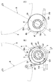
以下、本発明の実施の形態を図を用いて説明する。図1は本発明に係る輪転印刷機の胴装置を展開し一部を破断して示した正面図である。図2(a)は図1におけるII(a)矢視図、図2(b)は図1におけるII(b)矢視図である。
図1において、1A,1Bは左右のフレームであって、左側のフレーム1Aに設けた軸受孔2Aには、第2の偏心軸受としての外メタル3が回動自在に支持され、この外メタル3には第1の偏心軸受としての内メタル4が回動自在に支持されている。図2(b)に示すように、軸受孔2Aと外メタル3の外周との間および外メタル3の内周と内メタル4の外周との間には、これら外メタル3と内メタル4とが円滑に回動できるように、それぞれ潤滑油が供給されるクリアランス(以下、隙間という)3a,4aが設けられている。図1において、内メタル4のフレーム1Aの内側面に対接するフランジ部には、後述する当接部30aに当接する直線状に形成された係合面4cを有する係合突起4bが突設されている。図2(b)に示すように、この係合突起4bの係合面4cの形成方向Aは、後述するように外メタル3を回動操作することにより版胴7が移動する版胴7のひねり方向40と略一致している。
【0009】
右側のフレーム1Bには軸受孔2Bが設けられ、この軸受孔2Bには第1の偏心軸受としての内メタル6が回動自在に支持され、この内メタル6の外周と軸受孔2Bとの間にも隙間6aが設けられている。この内メタル6のフレーム1Bの内側面に対接するフランジ部には、当接部30aに当接する直線状に形成された係合面6cを有する係合突起6bが突設されている。7はゴム胴8に対接する版胴であって、左右の端軸7A,7Bが内メタル4,6にベアリング9,9を介して回転自在に軸支されている。左右の内メタル4,6の軸心C1は、版胴7の軸心Cに対してt1だけ偏心し、外メタル3の軸心C2は内メタル4の軸心C1に対してt2だけ偏心している。
【0010】
左右のフレーム1A,1Bの内側面には、左右一対のシリンダ11A,11Bが枢着されている。これらシリンダ11A,11Bのロッド12A,12Bは、左右の内メタル4,6のフレーム1A,1Bの内側面に対接するフランジ部に枢着され、その枢着部位13A,13Bと内メタル4,6の係合突起4b,6bとが版胴7の軸心Cを挟んで互いに略180°位相を違えるように位置付けられている。また、シリンダ11A,11Bのロッド12A,12Bの進退方向が、版胴7の軸心Cとゴム胴8の軸心C3とを結んだ線Bと略平行になるように構成されている。
【0011】
このような構成において、図2に示すように、シリンダ11A,11Bのロッド12A,12Bを前進させると、左右の内メタル4,6が版胴7の端軸7A,7Bの周りを回動するので、版胴7は内メタル4,6の軸心C1を回動中心として回動する。係合突起4b,6b後述するカム軸30,30の当接部30a,30aに当接すると、同図(a)において、内メタル6は当接部30aを回動中心として図中時計方向にわずかに回動する。したがって、図中41で示す部位において、内メタル6の外周の一部がフレーム1Bの軸受孔2Bの内周の一部を押圧する押圧部が形成される。この押圧部41は、ゴム胴8の軸心C3と版胴7の軸心Cとを結んだ線Bの延長線上に位置するように位置付けられている。
【0012】
また、同図(b)において、内メタル4は当接部30aを回動中心として図中反時計方向にわずかに回動する。したがって、図中42で示す部位において、内メタル4の外周の一部が外メタル3の内周の一部を押圧する押圧部が形成されるとともに、図中43で示す部位において、外メタル3の外周の一部がフレーム1Aの軸受孔2Aの内周の一部を押圧する押圧部が形成される。これら押圧部42,43は、ゴム胴8の軸心C3と版胴7の軸心Cとを結んだ線Bの延長線上に位置するように位置付けられている。また、押圧部41における内メタル6の軸受孔2Bへの押圧方向Dが線Bと同じ方向で、かつ押圧部42,43における内メタル4の外メタル3への押圧方向Dと外メタル3の軸受孔2Aへの押圧方向Dが線Bと同じ方向になっている。
【0013】
図1において、15はフレーム1Aにスタッドを介して固定されたモータであって、このモータ15にはモータ軸16の回転数を検出するポテンショメータ17が備えられ、モータ軸16にはギア18が軸着されている。20は回転自在でかつ軸方向の移動が規制された軸であって、ギア18に噛合するギア21が軸着され、上部に形成されたねじ部にはこま22が螺合し、このこま22は第1のレバー23の一端部に枢着されている。24は、互いに偏心した小径部24aと大径部24bが設けられた伝達軸であって、フレーム1Aに固定された支承部材25に回動自在に支持され、小径部24aは前記第1のレバー23の他端部に設けられた孔内に嵌合固定されている。
【0014】
伝達軸24の大径部24bは第2のレバー26の一端部に設けられた孔内に嵌合固定され、この第2のレバー26の他端部は前記外メタル3のフランジ部に枢着されている。したがって、モータ15が駆動され、モータ軸16の回転がギア18,21を介して軸20に伝達されると、こま22を介して第1のレバー23が伝達軸24を回動中心として回動するので、伝達軸24も一体的に回動する。伝達軸24の回動は大径部24bを介して第2のレバー26に伝達され、第2のレバー26が図2(b)に示すように図中矢印方向に移動するので、外メタル3が図中時計または反時計方向に回動する。このように、外メタル3が回動することにより、外メタル3の軸心C2が内メタル4の軸心C1に対して偏心していることにより、版胴7は図中矢印40で示すひねり方向に移動する。
【0015】
図1において、30はカム軸であって、左右のフレーム1A,1Bに穿孔した孔にブッシュ31を介して回動自在に支持され、左右のフレーム1A,1Bの内側から突出した一端部には、偏心したカム状の当接部30aが設けられている。33は図示しないゴム胴のメタルに回動自在に支持されたディスクであって、図示を省略した操作部材によって回動調整可能に構成されており、リンク部材34の一端部が枢着され、このリンク部材34の他端部にはレバー35の一端部が枢着されている。レバー35の他端部は、前記カム軸30の左右のフレーム1A,1Bの外側から突出した他端部に軸着されている。したがって、ディスク33を回動調整すると、リンク部材34およびレバー35を介して、カム軸30が回動するので、図2(b)において、当接部30aに当接する内メタル4の係合突起4bの位置が調整され、版胴7とゴム胴8とのニップ圧が調整される。
【0016】
次に、このような構成の輪転印刷機の胴装置におけるゴム胴8に対する版胴7の着脱動作を説明する。
シリンダ11A,11Bのロッド12A,12Bを前進させると、上述したように、左右の内メタル4,6が版胴7の端軸7A,7Bの周りを回動するので、版胴7は内メタル4,6の軸心C1を回動中心として回動する。係合突起4b,6bが後述するカム軸30,30の当接部30a,30aに当接することにより、内メタル4が押圧部42において外メタル3に押し付けられ、外メタル3および内メタル6が押圧部43,41において軸受孔2A,2Bに押し付けられ、版胴7がゴム胴8に適正なニップ圧をもって対接する。したがって、印刷中において版胴7とゴム胴8の外周に設けられた切欠きどうしが対向し、その後再び版胴7の外周とゴム胴8の外周が対接することにより、版胴7がゴム胴8の直径方向に僅かに移動しようとするが、押圧部41,42,43が形成されていることにより、この移動が阻止される。このため、版胴7とゴム胴8とが移動に起因する振動の発生を規制されるので印刷不良を防止できる。
【0017】
しかも、この押圧部41,42,43は、ゴム胴8の軸心C3と版胴7の軸心Cとを結んだ線Bの延長線上に位置するように位置付けられている。そして、押圧部41において、内メタル6の軸受孔2Bへの押圧方向Dが線Bと同じ方向で、かつ押圧部42,43において、内メタル4の外メタル3への押圧方向Dと外メタル3の軸受孔2Aへの押圧方向Dが線Bと同じ方向になっている。したがって、上述した版胴7とゴム胴8の切欠きに起因する版胴7の移動方向が、版胴7の軸心Cからゴム胴8の軸心C3方向、すなわち上述した押圧方向Dと反対方向であることから、版胴7の移動が規制されるので、印刷不良をより確実に防止できる。
【0018】
ここで、版胴7のひねり方向の調整が必要な場合には、図1においてモータ15を駆動すると、モータ軸16の回転がギア18,21を介して軸20に伝達され、こま22を介して第1のレバー23が伝達軸24を回動中心として回動するので、伝達軸24も一体的に回動する。伝達軸24の回動は大径部24bを介して第2のレバー26に伝達され、第2のレバー26が図2(b)に示すように図中矢印方向に移動するので、外メタル3が図中時計または反時計方向に回動し、版胴7が図中矢印40で示すひねり方向に移動する。このとき、版胴7のひねり方向40が係合突起4bの係合面4cの形成方向Aと一致していることにより、ひねり調整中に内メタル4と版胴7の端軸7Aとの位置関係が変化しないので、ゴム胴8に対する版胴7のニップ圧が適正に保たれる。
【0019】
図3は本発明の第2の実施の形態を示したもので、同図(a)は図1におけるII(a)矢視図、同図(b)は図1におけるII(b)矢視図である。
この第2の実施の形態が、上述した第1の実施の形態と異なる点は、シリンダ11A,11Bのロッド12A,12Bの進退方向が線Bと平行ではない点と、係合突起4bの係合面4cの形成方向Aが版胴7のひねり方向40と同じではない点にある。
【0020】
このような構成とすることにより、シリンダ11A,11Bのロッド12A,12Bを前進させると、左右の内メタル4,6が版胴7の端軸7A,7Bの周りを回動する。係合突起4b,6aが当接部30a,30aに当接することにより、内メタル4,6が当接部30a,30aを回動中心としてわずかに回動し、線Bの延長線上とは別の位置に位置付けられた押圧部41,42,43が形成される。この場合、シリンダ11A,11Bの駆動力を所定以上とすることにより、印刷中において版胴7とゴム胴8の外周に設けられた切欠きどうしが対向し、その後再び版胴7の外周とゴム胴8の外周が対接することにより、版胴7がゴム胴8の直径方向に僅かに移動しようとするが、押圧部41,42,43が形成されていることにより、この移動が阻止される。このため、版胴7とゴム胴8とが移動に起因する振動の発生を規制されるので印刷不良を防止できる。
【0021】
なお、本実施の形態においては、係合面4c,6cを係合突起4b,6bに形成したが、当接部30aに係合面を設けてもよい。
【0022】
【発明の効果】
以上説明したように、請求項1記載の発明によれば、第1の偏心軸受の一部が第2の偏心軸受の一部に押し付けられることにより、印刷中にこれら偏心軸受ががたつくことがないので印刷不良が防止できる。
【0023】
また、請求項2に係る発明によれば、ひねり見当の調整を行っても他方側の胴に対する一方側の胴のニップ圧がほぼ一定に保たれるので印刷品質が向上する。
【0024】
また、請求項3に係る発明によれば、印刷中に一方側の胴と他方側の胴との外周に設けた互いの切欠きが対向したとき、版胴7の移動が規制されるので、印刷不良をより確実に防止できる。
【図面の簡単な説明】
【図1】 本発明に係る輪転印刷機の胴装置を展開し一部を破断して示した正面図である。
【図2】 図2(a)は図1におけるII(a)矢視図、図2(b)は図1におけるII(b)矢視図である。
【図3】 本発明の第2の実施の形態を示したもので、同図(a)は図1におけるII(a)矢視図、同図(b)は図1におけるII(b)矢視図である。
【符号の説明】
2A,2B…軸受孔、3…外メタル、4,6…内メタル、7…版胴、7A,7B…端軸、8…ゴム胴、11A,11B…シリンダ、15…モータ、30a…当接部、40…ひねり方向、41,42,43…押圧部。[0001]
BACKGROUND OF THE INVENTION
The present invention relates to a cylinder device of a rotary printing press that performs attachment / detachment of a cylinder and a twist adjustment of the cylinder.
[0002]
[Prior art]
In various multi-color rotary printing presses such as offset printing machines, if the registration of the printing plates mounted on the plate cylinder does not match between the printing units of each color, the prints of each color are printed out of alignment. The cylinder device of the rotary printing press is provided with a plate registering device. A cylinder device of this type of rotary printing machine is disclosed in Japanese Utility Model Publication No. 64-42135. What is disclosed here supports one end shaft of the plate cylinder on one frame via an eccentric outer metal, and supports the other end shaft on the other frame via an eccentric inner metal and outer metal. is doing. In such a configuration, by rotating the pair of left and right outer metals, the plate cylinder is attached to and detached from the rubber cylinder and the nip pressure is adjusted. By rotating the inner metal, the twist of the plate cylinder is adjusted. Is called.
[0003]
[Problems to be solved by the invention]
In the above-described conventional rotary printing press cylinder device, in order to smoothly rotate the eccentric inner metal and outer metal, the amount of eccentricity is supported between the inner metal and the outer metal and between the outer metal and the frame. In general, there is a gap called a clearance through which lubricating oil is supplied. A notch for winding the plate is provided on the outer periphery of the plate cylinder, and a notch for winding the blanket is provided on the rubber cylinder. For this reason, the printing pressure is released when the notches of the plate cylinder and the rubber cylinder face each other during printing, and then the diameter of the cylinder becomes the diameter of the rubber cylinder when the outer periphery of the plate cylinder and the outer periphery of the rubber cylinder come into contact again. Vibration is generated due to slight movement in the direction. In addition, this vibration becomes larger when the gap between the metals becomes larger due to wear, and stripes in the axial direction of the plate cylinder, so-called shock eyes are generated, which causes the quality of printing to deteriorate.
[0004]
The present invention has been made in view of the above-described conventional problems, and an object of the present invention is to provide a cylinder device of a rotary printing press with improved printing quality.
[0005]
[Means for Solving the Problems]
In order to achieve this object, the invention according to claim 1 is directed to a pair of first eccentric bearings that rotatably support both end portions of one cylinder and one of the pair of first eccentric bearings. A second eccentric bearing that pivotally supports the eccentric bearing, a pair of support members that respectively pivotally support the other eccentric bearing of the second eccentric bearing and the first eccentric bearing, and the first eccentric bearing. A first driving means for rotating the bearing; a second driving means for rotating the second eccentric bearing; and a cylinder on the one side by driving the first driving means provided on the support member side. Is provided with a contact member with which a contact portion provided in the first eccentric bearing comes into contact.
Therefore, when the first cylinder comes into contact with the other cylinder by the driving of the first driving means, the first eccentric bearing contacts the contact member, and the first eccentric bearing rotates the contact member. It rotates about the center, and a part of the first eccentric bearing is pressed against a part of the second eccentric bearing.
[0006]
The invention according to claim 2 is the invention according to claim 1, wherein the contact surface or the support member is provided in the contact portion provided in the first eccentric bearing and contacts the contact member. The contact surface provided on the contact member provided on the side and contacted by the contact portion is formed in substantially the same direction as the twisting direction of the barrel on the one side.
Therefore, even if the cylinder on one side is moved to adjust the twist of the cylinder, the nip pressure of the cylinder on the one side with respect to the cylinder on the other side is kept substantially constant.
[0007]
The invention according to claim 3 is the invention according to claim 1, wherein the pressing portion between the first eccentric bearing and the second eccentric bearing, and the pressing between the second eccentric bearing and the support member. Is positioned substantially on a connection line connecting the axial centers of the one cylinder and the other cylinder.
Therefore, the first eccentric bearing and the second eccentric bearing are not displaced when the notches provided on the outer periphery of the one cylinder and the other cylinder face each other.
[0008]
DETAILED DESCRIPTION OF THE INVENTION
Hereinafter, embodiments of the present invention will be described with reference to the drawings. FIG. 1 is a front view showing a cylinder device of a rotary printing press according to the present invention expanded and partially broken. 2A is a view taken in the direction of arrow II (a) in FIG. 1, and FIG. 2B is a view taken in the direction of arrow II (b) in FIG.
In FIG. 1, 1A and 1B are left and right frames, and an outer metal 3 as a second eccentric bearing is rotatably supported in a
[0009]
A
[0010]
A pair of left and
[0011]
In such a configuration, as shown in FIG. 2, when the
[0012]
Further, in FIG. 2B, the inner metal 4 slightly rotates counterclockwise in the drawing with the
[0013]
In FIG. 1,
[0014]
The large-
[0015]
In FIG. 1,
[0016]
Next, the attaching / detaching operation of the
When the
[0017]
In addition, the
[0018]
Here, when adjustment of the twisting direction of the
[0019]
FIG. 3 shows a second embodiment of the present invention. FIG. 3 (a) is a view taken in the direction of arrow II (a) in FIG. 1, and FIG. 3 (b) is a view taken in the direction of arrow II (b) in FIG. FIG.
This second embodiment differs from the first embodiment described above in that the forward and backward directions of the
[0020]
With this configuration, when the
[0021]
In the present embodiment, the engagement surfaces 4c and 6c are formed on the
[0022]
【The invention's effect】
As described above, according to the first aspect of the present invention, a part of the first eccentric bearing is pressed against a part of the second eccentric bearing, so that the eccentric bearing does not rattle during printing. Therefore, printing defects can be prevented.
[0023]
According to the second aspect of the invention, even if the twist registration is adjusted, the nip pressure of the cylinder on one side with respect to the cylinder on the other side is kept substantially constant, so that the print quality is improved.
[0024]
Further, according to the invention according to claim 3, when the notches provided on the outer periphery of the cylinder on the one side and the cylinder on the other side face each other during printing, the movement of the
[Brief description of the drawings]
FIG. 1 is a front view showing a cylinder device of a rotary printing press according to the present invention expanded and partially broken.
2A is a view taken in the direction of arrow II (a) in FIG. 1, and FIG. 2B is a view taken in the direction of arrow II (b) in FIG.
3A and 3B show a second embodiment of the present invention, in which FIG. 3A is a view taken in the direction of arrow II (a) in FIG. 1, and FIG. FIG.
[Explanation of symbols]
2A, 2B ... bearing hole, 3 ... outer metal, 4, 6 ... inner metal, 7 ... plate cylinder, 7A, 7B ... end shaft, 8 ... rubber cylinder, 11A, 11B ... cylinder, 15 ... motor, 30a ... contact Part, 40 ... twist direction, 41, 42, 43 ... pressing part.
Claims (5)
Priority Applications (6)
| Application Number | Priority Date | Filing Date | Title |
|---|---|---|---|
| JP2000189457A JP4611493B2 (en) | 2000-06-23 | 2000-06-23 | Rotary printing press cylinder |
| AT01114483T ATE369981T1 (en) | 2000-06-23 | 2001-06-15 | CYLINDER DEVICE FOR A ROTARY PRINTING PRESS |
| ES01114483T ES2291247T3 (en) | 2000-06-23 | 2001-06-15 | CYLINDER DEVICE FOR A ROTARY PRESS. |
| EP01114483A EP1167027B1 (en) | 2000-06-23 | 2001-06-15 | Cylinder apparatus for a rotary printing press |
| DE60129886T DE60129886T2 (en) | 2000-06-23 | 2001-06-15 | Cylinder device for a rotary printing machine |
| US09/892,032 US6601504B2 (en) | 2000-06-23 | 2001-06-25 | Cylinder apparatus for rotary printing press |
Applications Claiming Priority (1)
| Application Number | Priority Date | Filing Date | Title |
|---|---|---|---|
| JP2000189457A JP4611493B2 (en) | 2000-06-23 | 2000-06-23 | Rotary printing press cylinder |
Publications (3)
| Publication Number | Publication Date |
|---|---|
| JP2002001904A JP2002001904A (en) | 2002-01-08 |
| JP2002001904A5 JP2002001904A5 (en) | 2007-07-12 |
| JP4611493B2 true JP4611493B2 (en) | 2011-01-12 |
Family
ID=18689086
Family Applications (1)
| Application Number | Title | Priority Date | Filing Date |
|---|---|---|---|
| JP2000189457A Expired - Fee Related JP4611493B2 (en) | 2000-06-23 | 2000-06-23 | Rotary printing press cylinder |
Country Status (6)
| Country | Link |
|---|---|
| US (1) | US6601504B2 (en) |
| EP (1) | EP1167027B1 (en) |
| JP (1) | JP4611493B2 (en) |
| AT (1) | ATE369981T1 (en) |
| DE (1) | DE60129886T2 (en) |
| ES (1) | ES2291247T3 (en) |
Families Citing this family (6)
| Publication number | Priority date | Publication date | Assignee | Title |
|---|---|---|---|---|
| US6886458B1 (en) * | 2003-12-18 | 2005-05-03 | Shinohara Machinery Co., Ltd. | Apparatus for adjusting printing pressure of satellite-type printing press |
| CN101137507A (en) * | 2005-05-20 | 2008-03-05 | 小森公司 | Register adjustment device for rotating body |
| JP2009000883A (en) | 2007-06-21 | 2009-01-08 | Komori Corp | Printing quality control method and apparatus for printing press |
| JP2009000881A (en) | 2007-06-21 | 2009-01-08 | Komori Corp | Printing quality control method and apparatus for relief printing press |
| DE102009055655A1 (en) * | 2009-11-24 | 2011-05-26 | Schaeffler Technologies Gmbh & Co. Kg | Eccentric adjustment on bearings of printing presses |
| JP6418630B2 (en) * | 2014-05-14 | 2018-11-07 | 株式会社小森コーポレーション | Printing machine cylinder |
Family Cites Families (15)
| Publication number | Priority date | Publication date | Assignee | Title |
|---|---|---|---|---|
| US2986086A (en) * | 1959-02-27 | 1961-05-30 | Miller Printing Machinery Co | Antifriction eccentric journaling mounting for rotatable member |
| US3786749A (en) * | 1972-04-07 | 1974-01-22 | Rockwell International Corp | Printing press cylinder support and control |
| DD125630A1 (en) * | 1976-05-13 | 1977-05-04 | ||
| DE2725030C3 (en) * | 1977-06-03 | 1982-01-07 | M.A.N. Maschinenfabrik Augsburg-Nürnberg AG, 8900 Augsburg | Changeover device for a convertible satellite printing unit |
| US4458591A (en) * | 1982-09-30 | 1984-07-10 | Harris Graphics Corporation | Rotary printing press |
| JPS59142148A (en) * | 1983-02-03 | 1984-08-15 | Komori Printing Mach Co Ltd | Print varnishing equipment |
| JPS59142150A (en) * | 1983-02-03 | 1984-08-15 | Komori Printing Mach Co Ltd | Varnish coater for print |
| DE3412812C1 (en) * | 1984-04-05 | 1985-06-27 | M.A.N.- Roland Druckmaschinen AG, 6050 Offenbach | Switching device for the blanket cylinders of a printing unit for a web-fed offset printing machine |
| DE3614027A1 (en) * | 1986-04-25 | 1987-10-29 | Roland Man Druckmasch | ACTUATING DEVICE FOR FIVE-CYLINDER PRINTING UNITS FROM OFFSET ROTATIONAL PRINTING MACHINES |
| JPS6442135A (en) | 1987-08-07 | 1989-02-14 | Mitsubishi Electric Corp | Semiconductor device |
| JP2524289Y2 (en) | 1991-05-15 | 1997-01-29 | 株式会社小森コーポレーション | Printing cylinder printing pressure adjustment device |
| DE9115598U1 (en) * | 1991-09-09 | 1992-04-23 | Koenig & Bauer AG, 8700 Würzburg | Arrangement for adjusting eccentric bushings for cylinders of printing machines |
| DE19515692A1 (en) * | 1995-04-28 | 1996-10-31 | Heidelberger Druckmasch Ag | Adjusting device for a blanket cylinder |
| US5722323A (en) * | 1995-09-13 | 1998-03-03 | Goss Graphic Systems, Inc. | Blanket cylinder throw-off device |
| US6347585B1 (en) * | 1998-08-04 | 2002-02-19 | Goss Graphic Systems, Inc. | Variable gap stabilizer |
-
2000
- 2000-06-23 JP JP2000189457A patent/JP4611493B2/en not_active Expired - Fee Related
-
2001
- 2001-06-15 EP EP01114483A patent/EP1167027B1/en not_active Expired - Lifetime
- 2001-06-15 ES ES01114483T patent/ES2291247T3/en not_active Expired - Lifetime
- 2001-06-15 DE DE60129886T patent/DE60129886T2/en not_active Expired - Lifetime
- 2001-06-15 AT AT01114483T patent/ATE369981T1/en not_active IP Right Cessation
- 2001-06-25 US US09/892,032 patent/US6601504B2/en not_active Expired - Lifetime
Also Published As
| Publication number | Publication date |
|---|---|
| DE60129886T2 (en) | 2008-04-30 |
| DE60129886D1 (en) | 2007-09-27 |
| ES2291247T3 (en) | 2008-03-01 |
| US20010054361A1 (en) | 2001-12-27 |
| EP1167027A3 (en) | 2004-01-14 |
| EP1167027A2 (en) | 2002-01-02 |
| US6601504B2 (en) | 2003-08-05 |
| ATE369981T1 (en) | 2007-09-15 |
| EP1167027B1 (en) | 2007-08-15 |
| JP2002001904A (en) | 2002-01-08 |
Similar Documents
| Publication | Publication Date | Title |
|---|---|---|
| JP5389406B2 (en) | Printing machine with pillow | |
| JPH0796598A (en) | Press with blanket cylinder-unloading device and its operating method | |
| JP4611493B2 (en) | Rotary printing press cylinder | |
| JP2938491B2 (en) | Printing machine ink unit | |
| EP1110725A2 (en) | Printing cylinder for offset printing | |
| JPWO2006123728A1 (en) | Rotating body registration adjustment device | |
| US5601021A (en) | Printing cylinder holding apparatus for printing machine | |
| JPH082630B2 (en) | Offset printing machine | |
| JP2726015B2 (en) | Printing cylinder position adjustment device with removable blanket | |
| JP3638074B2 (en) | Swing device for sheet-fed rotary printing press | |
| JPH04226362A (en) | Roller driving device for rotary printing machine | |
| JP2005022106A (en) | Roller support device | |
| JP2597629Y2 (en) | Roller holding device for printing press | |
| JP3103166U (en) | Rotary printing press with a furnisher roll. | |
| JPS63251237A (en) | Inking device of rotary printing press | |
| JPH1076636A (en) | Roller device for rotary printing press | |
| JPS6213800Y2 (en) | ||
| JP4189628B2 (en) | Printer | |
| JP2588289Y2 (en) | Nip pressure adjustment device for printing press | |
| JPH0745247B2 (en) | Roller contacting / separating device in printing machine | |
| JP3637953B2 (en) | Paper feed roller support device for ink jet recording apparatus | |
| JP2875856B2 (en) | Swing rider drive | |
| JPH0438999Y2 (en) | ||
| JPH0143234Y2 (en) | ||
| JPH09272196A (en) | Ink device for printer |
Legal Events
| Date | Code | Title | Description |
|---|---|---|---|
| A521 | Request for written amendment filed |
Free format text: JAPANESE INTERMEDIATE CODE: A523 Effective date: 20070525 |
|
| A621 | Written request for application examination |
Free format text: JAPANESE INTERMEDIATE CODE: A621 Effective date: 20070525 |
|
| A131 | Notification of reasons for refusal |
Free format text: JAPANESE INTERMEDIATE CODE: A131 Effective date: 20100525 |
|
| A521 | Request for written amendment filed |
Free format text: JAPANESE INTERMEDIATE CODE: A523 Effective date: 20100722 |
|
| TRDD | Decision of grant or rejection written | ||
| A01 | Written decision to grant a patent or to grant a registration (utility model) |
Free format text: JAPANESE INTERMEDIATE CODE: A01 Effective date: 20100914 |
|
| A01 | Written decision to grant a patent or to grant a registration (utility model) |
Free format text: JAPANESE INTERMEDIATE CODE: A01 |
|
| A61 | First payment of annual fees (during grant procedure) |
Free format text: JAPANESE INTERMEDIATE CODE: A61 Effective date: 20101014 |
|
| FPAY | Renewal fee payment (event date is renewal date of database) |
Free format text: PAYMENT UNTIL: 20131022 Year of fee payment: 3 |
|
| R150 | Certificate of patent or registration of utility model |
Ref document number: 4611493 Country of ref document: JP Free format text: JAPANESE INTERMEDIATE CODE: R150 Free format text: JAPANESE INTERMEDIATE CODE: R150 |
|
| FPAY | Renewal fee payment (event date is renewal date of database) |
Free format text: PAYMENT UNTIL: 20141022 Year of fee payment: 4 |
|
| LAPS | Cancellation because of no payment of annual fees |