JP4580048B2 - Automatic measuring method and automatic measuring apparatus for ball end mill tool - Google Patents
Automatic measuring method and automatic measuring apparatus for ball end mill tool Download PDFInfo
- Publication number
- JP4580048B2 JP4580048B2 JP20752599A JP20752599A JP4580048B2 JP 4580048 B2 JP4580048 B2 JP 4580048B2 JP 20752599 A JP20752599 A JP 20752599A JP 20752599 A JP20752599 A JP 20752599A JP 4580048 B2 JP4580048 B2 JP 4580048B2
- Authority
- JP
- Japan
- Prior art keywords
- tool
- end mill
- ball end
- spindle
- maximum value
- Prior art date
- Legal status (The legal status is an assumption and is not a legal conclusion. Google has not performed a legal analysis and makes no representation as to the accuracy of the status listed.)
- Expired - Lifetime
Links
Images


Landscapes
- Machine Tool Sensing Apparatuses (AREA)
Description
【0001】
【発明の属する技術分野】
本発明は、ボールエンドミル工具の自動測定方法および自動測定装置に関する。詳しくは、主軸にボールエンドミル工具を装着したままの状態において、そのボールエンドミル工具の工具データを自動測定するボールエンドミル工具の自動測定方法および自動測定装置に関する。
【0002】
【背景技術】
図8は、ワークWを工具T(ボールエンドミル工具Tb)で加工する際の関係を示している。なお、ここでは、説明の便宜上、2軸(X軸およびY軸)平面を示している。同図において、
MO:機械固有の機械原点(座標X0,Y0)
WO:ワークの加工原点(座標:Xw,Yw)
である。
【0003】
一般に、加工プログラムは、ワークWの加工原点WOを基準に作成される。つまり、ワークWの加工原点WOを基準に、ワークWの最終加工形状を考慮して作成される。
作成した加工プログラムを用いて実際にワークWを加工するに際しては、工具Tbの形状を考慮して、工具長補正、工具径補正など、数値制御装置の加工のための補正機能が用いられる。
【0004】
数値制御装置の補正機能に関して、実際の加工プログラムを補正するには、ボールエンドミル工具Tbによって切削するための加工位置の座標が必要である。
とくに、図8に示すように、主軸ヘッドのアタッチメントによって、ボールエンドミル工具Tbが傾斜して設定された場合、そのボールエンドミル工具Tbがある座標位置に位置決めされたとき、その工具Tbの各軸方向の最大値、この場合、Y軸方向のY(min)およびX軸方向のX(max)の座標位置が必要となる。
【0005】
このような工具データが判れば、これを基に加工プログラムを補正することができるからである。たとえば、図8において、実際にワークWの加工原点WOから座標(X1、Y1)に工具Tを移動させるプログラムが作成されていたとすると、工具Tを形状を考慮して、実際には、工具Tを座標(X2、Y2)に移動させることができるからである。
【0006】
しかしながら、従来の工作機械においては、ボールエンドミル工具を主軸に装着したままの状態では、工具の長さ、太さ(径)など工具データに関する測定は行われていない。
従来、ボールエンドミル工具について工具データに測定するには、ツールプリセッタなどを使用して、ボールエンドミル工具の形状を観測し、ボールエンドミル工具の長さ、太さ(径)などの工具データを手動により測定していた。
【0007】
【発明が解決しようとする課題】
しかし、従来のような工具データの測定法では、ボールエンドミル工具を主軸に装着した状態で工具データを測定するのではないから、主軸ヘッドのアタッチメントによって傾斜して設定された場合では、工具形状の正確なデータを把握しづらい。
【0008】
また、ワークの自動加工にあたって、事前に工具データの蓄積のための時間を必要とするため、ワーク加工のトータル時間が長くなるという問題もある。しかも、同一のボールエンドミル工具を長期に使用した場合、摩耗などで形状が変化したときも、その都度、ボールエンドミル工具を主軸から外したのち、この外した工具を手動計測しなければならないため、ワーク加工のトータル時間が長くなってしまうという問題があった。
【0009】
本発明の目的は、このような従来の課題を解消し、主軸にボールエンドミル工具を装着した状態で工具形状を測定できるようにすることにより、正確に工具形状を測定できるうえ、ワーク加工のトータル時間を短縮できるボールエンドミル工具の自動測定方法および自動測定装置を提供することにある。
【0010】
【課題を解決するための手段】
本発明のボールエンドミル工具の自動測定方法および自動測定装置は、上記目的を達成するため、次の構成を採用する。
請求項1に記載のボールエンドミル工具の自動測定方法は、ワークをセットするテーブルと、ボールエンドミル工具を装着可能な主軸と、前記テーブルおよび前記主軸を相対移動させるとともに前記主軸の姿勢を変化させる移動機構と、制御装置とを有する工作機械において、前記ボールエンドミル工具の形状を測定するボールエンドミル工具の自動測定方法であって、略立方体の基台と、この基台の5つの面に該面に対して直交する方向へ変位可能に設けられた5つの基準面と、この各基準面の変位を検出して出力するセンサとを有する工具検出装置を前記テーブルに固定する工程と、前記制御装置のマクロプログラムにより実行され、前記主軸にキャリブレーション用の標準工具を装着し、その標準工具を前記工具検出装置の複数の基準面に順番に接触させ、このときの工具検出装置からの出力および主軸の移動位置から各基準面の座標を測定する基準面測定工程と、前記制御装置のマクロプログラムにより実行され、前記主軸に前記ボールエンドミル工具を装着し、このボールエンドミル工具が実際に加工する姿勢になるように前記主軸の姿勢を制御したのち、そのボールエンドミル工具が前記工具検出装置の複数の基準面に接触するように主軸を移動させ、この接触状態において、ボールエンドミル工具を回転させつつ工具検出装置の出力を監視してその最大値を求める最大値測定工程と、を備えたことを特徴とする。
【0011】
この発明によれば、予め、主軸にキャリブレーション用の標準工具を装着し、その標準工具を工具検出装置の基準面に接触させ、このときの工具検出装置からの出力および主軸の移動位置から基準面の座標を測定しておく。
次に、主軸に測定対象のボールエンドミル工具を装着し、そのボールエンドミル工具が、予め測定した工具検出装置の基準面に接触するように主軸を移動させる。この状態、つまり、ボールエンドミル工具が工具検出装置の基準面に接触した状態において、ボールエンドミル工具を回転させつつ工具検出装置の出力を監視してその最大値を求める。そして、この最大値を補正値として加工プログラムの補正を行う。
従って、主軸にボールエンドミル工具を装着した状態で工具形状を測定できるから、正確に工具形状を測定できる。しかも、都度、ボールエンドミル工具を主軸から取り外して測定しなくてもよいから、測定時間、ひいては、ワーク加工のトータル時間を短縮できる。
【0012】
請求項2に記載のボールエンドミル工具の自動測定方法は、請求項1に記載のボールエンドミル工具の自動測定方法において、前記最大値測定工程は、主軸にボールエンドミル工具を装着する工具装着工程と、ボールエンドミル工具が工具検出装置の基準面に接触するように主軸を移動さて停止させる主軸移動工程と、ボールエンドミル工具を工具検出装置の基準面に接触させた状態で回転させる工具回転工程と、工具検出装置の出力を監視してその最大値を求める最大値検出工程とを含むことを特徴とする。
この発明によれば、最大値測定工程が、工具装着工程と、主軸移動工程と、工具回転工程と、最大値検出工程から構成するとともに、主軸の移動完了後に工具を回転させて、工具検出装置の出力を監視してその最大値を求めるようにしたから、ボールエンドミル工具が基準面に接触したときにはボールエンドミル工具が回転していないから、ボールエンドミル工具の接触時に工具検出装置の基準面が損傷される虞が少ない。
【0013】
請求項3に記載のボールエンドミル工具の自動測定方法は、請求項1または請求項2に記載のボールエンドミル工具の自動測定方法において、前記最大値測定工程において、前記ボールエンドミル工具を加工時とは逆回転させつつ工具検出装置の出力を監視してその最大値を求めることを特徴とする。
この発明によれば、最大値測定工程において、ボールエンドミル工具を加工時とは逆回転させつつ工具検出装置の出力を監視するようにしたから、ボールエンドミル工具の回転によって工具検出装置の基準面が切削されるような虞がない。
【0014】
請求項4に記載のボールエンドミル工具の自動測定方法は、請求項1または請求項2に記載のボールエンドミル工具の自動測定方法において、前記最大値測定工程において、前記ボールエンドミル工具を加工時の最低回転数より低速な回転数でかつ加工時とは逆回転で回転させつつ工具検出装置の出力を監視してその最大値を求めることを特徴とする。
この発明によれば、最大値測定工程において、ボールエンドミル工具を加工時の最低回転数より低速な回転数でかつ加工時とは逆回転で回転させるようにしたから、請求項3に記載の発明に比べ、より工具検出装置の基準面の破損を防止できる。
【0015】
請求項5に記載ボールエンドミル工具の自動測定装置は、ワークをセットするテーブルと、工具を装着可能な主軸と、前記テーブルおよび前記主軸を相対移動させるとともに前記主軸の姿勢を変化させる移動機構と、前記主軸にキャリブレーション用の標準工具および測定対象のボールエンドミル工具を選択的に装着するための工具交換装置と、前記テーブルに固定された略立方体の基台と、この基台の5つの面に該面に対して直交する方向へ変位可能に設けられた5つの基準面と、この各基準面の変位を検出して出力するセンサとを有する工具検出装置と、前記移動機構および工具交換装置を制御し、かつ、前記工具検出装置からの信号を取り込み処理する制御装置とを備え、前記制御装置は、前記主軸にキャリブレーション用の標準工具が装着された状態において、その標準工具を前記工具検出装置の複数の基準面に順番に接触させ、このときの工具検出装置からの出力および移動機構の移動位置から各基準面の座標を測定する基準面測定手段と、前記主軸に測定対象のボールエンドミル工具が装着された状態において、このボールエンドミル工具が実際に加工する姿勢になるように前記主軸の姿勢を制御したのち、そのボールエンドミル工具が前記工具検出装置の複数の基準面に接触するように移動機構を移動させ、この接触状態において、ボールエンドミル工具を回転させつつ工具検出装置からの出力を監視してその最大値を求める最大値測定手段とを含む、を備えたことを特徴とする。
【0016】
この発明によれば、請求項1に記載した発明と同様に、主軸にボールエンドミル工具を装着した状態で工具形状を測定できるから、正確に工具形状を測定でき、しかも、都度、ボールエンドミル工具を主軸から取り外して測定しなくてもよいから、測定時間、ひいては、ワーク加工のトータル時間を短縮できる。
【0017】
請求項6に記載のボールエンドミル工具の自動測定装置は、請求項5に記載のボールエンドミル工具の自動測定装置において、前記最大値測定手段は、前記ボールエンドミル工具を加工時とは逆回転させつつ工具検出装置の出力を監視してその最大値を求めることを特徴とする。
この発明によれば、請求項3に記載の発明と同様に、ボールエンドミル工具を加工時とは逆回転させつつ工具検出装置の出力を監視するようにしたから、ボールエンドミル工具の回転によって工具検出装置の基準面が切削されるような虞がない。
【0018】
請求項7に記載のボールエンドミル工具の自動測定装置は、請求項5に記載のボールエンドミル工具の自動測定装置において、前記最大値測定手段は、前記ボールエンドミル工具を加工時の最低回転数より低速な回転数でかつ加工時とは逆回転で回転させつつ工具検出装置の出力を監視してその最大値を求めることを特徴とする。
この発明によれば、請求項4に記載の発明と同様に、ボールエンドミル工具を加工時の最低回転数より低速な回転数でかつ加工時とは逆回転で回転させるようにしたから、より工具検出装置の基準面の破損を防止できる。
【0019】
【発明の実施の形態】
以下、本発明の一実施形態を図面に基づいて説明する。
図1は本発明のボールエンドミル工具の自動測定装置を備えた工作機械の本体を示している(正面)。同工作機械の本体は、テーブル1と、このテーブル1の前後方向(Y軸方向)へ移動可能に設けられた門形フレーム2と、この門形フレーム2の水平ビーム2Aに沿って左右方向(X軸方向)へ移動可能に設けられたサドル3と、このサドル3に上下方向へ昇降可能に設けられた昇降プレート4と、この昇降プレート4に前記Y軸と平行な軸を中心として旋回可能に設けられた旋回プレート5と、この旋回プレート5に設けられた主軸8を有する主軸ヘッド6とから構成されている。ここに、門形フレーム2、サドル3、昇降プレート4および旋回プレート5は、ワークをセットするテーブル1と工具を装着可能な主軸8とをX,Y,Z軸方向へ相対移動させる移動機構10を構成している。
【0020】
前記テーブル1には、ワーク(図示省略)が取り付けられるとともに、工具が接触したとき変位可能な基準面を有し、その基準面の変位を検出して出力する工具検出装置11が設けられている。
前記主軸ヘッド6は、前記旋回プレート5に固定されたハウジング7と、このハウジング7(図示省略)に軸受を介して回転可能に支承された主軸8と、この主軸8を回転駆動させる主軸モータ9とを備える。主軸8には、工具交換装置(図3参照)によって加工に必要な工具、たとえば、ボールエンドミル工具Tb(図6参照)が自動的に装着されるとともに、キャリブレーション用の標準工具Ta(図5参照)が装着されるようになっている。
【0021】
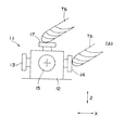
図2は前記工具検出装置11を示している。同工具検出装置11は、略立方体の基台12と、この基台12の5つの面に、つまり、12X1,12X2,12Y1,12Y2,12Z面に設けられた5つの基準面13〜17とを備える。各基準面13〜17は、基台2内に設けられた弾性部材によって各軸方向へ変位可能で、常時は突出した位置に保たれている。基台12内には、各基準面13〜17の変位を検出するセンサが設けられ、このセンサで検出された値が外部へ出力されるようになっている。従って、この工具検出装置11によれば、少なくともX、Y、Zの3軸方向の変位を5方向から測定できるようになっている。
【0022】
図3は工作機械の制御手段のブロック図を示している。同制御手段は、前記工具検出装置11からの出力信号を入力とする数値制御装置21と、シーケンスコントローラ22と、このシーケンスコントローラ22からの指令に基づいて前記主軸モータ9の駆動を制御する主軸モータドライブユニット24および工具交換装置25とを備える。
数値制御装置21は、工作機械を数値制御するために使用され、マクロプログラム23により工作機械に適した専用的機能を実現できる。
シーケンスコントローラ22は、数値制御装置21の加工プログラムをもとに、加工プログラムのうちの主にMコードの制御を行う。
主軸モータドライブユニット24は、シーケンスコントローラ22からの出力を受け、主軸モータ9を駆動する。
【0023】
次に、本実施形態の作用を説明する。
ボールエンドミル工具Tbの自動測定にあたっては、図4のフローチャートに示す手順で行う。
まず、キャリブレーション用の標準工具Taを主軸8に装着する(ST1)。
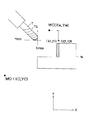
たとえば、図5に示すように、工具長Lおよび工具径Dが既知のキャリブレーション用の標準工具Taを主軸8に装着する。
次に、その標準工具Taを工具検出装置11へ位置決めする(ST2)。つまり、標準工具Taが工具検出装置11の基準面13〜17に接触するように、移動機構10を駆動させる。たとえば、門形フレーム2をY軸方向へ、サドル3をX軸方向へ、昇降プレート4をZ軸方向へ移動させる。
このとき、標準工具Taを工具検出装置11の5つの基準面13〜17に順番に接触させ、そのときの主軸8の移動位置(各軸の移動位置)および工具検出装置11の出力から、各基準面13〜17の座標を求める(ST3)。
【0024】
次に、ボールエンドミル工具Tbを主軸8に装着する(ST4)。これには、工具交換装置25を駆動させて、今まで装着されていたキャリブレーション用の標準工具Taを主軸8から外し、新たにボールエンドミル工具Tbを主軸8に装着する。このとき、ボールエンドミル工具Tbを実際に加工する姿勢に制御する。たとえば、ボールエンドミル工具Tbを傾斜させた状態で加工を行う場合には、旋回プレート5を旋回させてボールエンドミル工具Tbを傾斜した姿勢にセットする。
次に、そのボールエンドミル工具Tbを工具検出装置11へ位置決めする(ST5)。つまり、そのボールエンドミル工具Tbが各軸方向の基準面13〜17に接触するように主軸8を移動させる。たとえば、最初にX軸方向の基準面14に接触するように、図6の(A)の位置まで移動させる。
【0025】
この後、ボールエンドミル工具Tbを加工時の最低回転数より低速な回転数でかつ加工時とは逆回転で回転させ(ST6)、このときの工具検出装置11の出力を取り込んでその最大値を求めたのち(ST7)、回転を停止させる(ST8)。これにより、X軸方向の形状を測定できる。
これをY軸およびZ軸の基準面について行い、各軸方向の形状の測定を行ったのち、最大値と工具理論値との差分を計算し(ST9)、その各差分を補正テーブルにストアする(ST10)。
【0026】
たとえば、▲1▼工具径補正の場合には、ST10において、マクロにより、図7(A)に示す工具径補正テーブルDTを作る。つまり、ST9で計算した工具径補正データ(最大値と工具理論値との差分)をV2000〜エリアにストアして工具径補正テーブルDTを作る。この場合、加工プログラムの補正にあたっては、たとえば、G41D00(工具径補正右)またはG42D00(工具径補正左)によって補正データを読み出して補正を行うことができる。
また、▲2▼工具長補正の場合には、ST10において、マクロにより、図7(B)に示す工具長補正テーブルHTを作る。つまり、ST9で計算した工具長補正データ(最大値と工具理論値との差分)をV2500〜エリアにストアして工具長補正テーブルHTを作る。この場合、加工プログラムの補正にあたっては、たとえば、G43H00によって補正データを読み出して補正を行うことができる。
【0027】
さらに、▲3▼座標系設定の場合には、GコードのG92を用いて、マクロで設定したデータを使用して補正する。
なお、これらの▲1▼工具径補正、▲2▼工具長補正および▲3▼座標系設定を組み合わせて補正を行うようにしてもよい。
【0028】
従って、本実施形態によれば、主軸8にボールエンドミル工具Tbを装着した状態で工具形状を測定できるから、正確に工具形状を測定でき、しかも、都度、ボールエンドミル工具Tbを主軸8から取り外して測定しなくてもよいから、測定時間、ひいては、ワーク加工のトータル時間を短縮できる。
【0029】
また、ボールエンドミル工具Tbの最大値の測定において、ボールエンドミル工具Tbを加工時とは逆回転させつつ工具検出装置11の出力を監視するようにしたから、ボールエンドミル工具Tbの回転によって工具検出装置11の基準面13〜17が切削されるような虞がない。
しかも、その際、ボールエンドミル工具Tbを加工時の最低回転数より低速な回転数でかつ加工時とは逆回転で回転させるようにしたから、より工具検出装置11の基準面13〜17の破損を防止できる。
【0030】
なお、上記実施形態では、ワークを載置するテーブル1に対して、ボールエンドミル工具TbをX,Y,Z軸方向へ移動させる構成であったが、これとは逆に、ボールエンドミル工具Tbに対して、ワークを載置するテーブル1をX,Y,Z軸方向へ移動させる構成でもよい。
また、上記実施形態では、加工の最初、あるいは、途中において、キャリブレーション用の標準工具Taを用いて基準面13〜17の測定を行ったが、加工を行う前に事前に測定しておいてもよい。このようにすれば、ワークの加工時においては、ボールエンドミル工具の形状測定のみを行えばよいから、よりワーク加工のトータル時間を短縮できる。
【0031】
【発明の効果】
本発明のボールエンドミル工具の自動測定方法および自動測定装置によれば、主軸にボールエンドミル工具を装着した状態で工具形状を測定できるようにすることにより、正確に工具形状を測定できるうえ、ワーク加工のトータル時間を短縮できる。
【図面の簡単な説明】
【図1】本発明のボールエンドミル工具の自動測定装置を備えた工作機械の本体を示す正面図である。
【図2】同上実施形態において用いられる工具検出装置を示す斜視図である。
【図3】同上実施形態における工作機械の制御装置を示すブロック図である。
【図4】同上実施形態におけるボールエンドミル工具の自動測定工程を示すフローチャートである。
【図5】同上実施形態において、主軸にキャリブレーション用の標準工具を装着した状態を示す斜視図である。
【図6】同上実施形態において、主軸に装着したボールエンドミル工具を工具検出装置の基準面に接触させた状態を示す正面図である。
【図7】同上実施形態における補正テーブルを示すもので、図7(A)は工具径補正テーブル、図7(B)は工具長補正テーブルをそれぞれ示している。
【図8】従来例(ボールエンドミル工具を用いてワークを加工する際の関係)を示す図である。
【符号の説明】
1 テーブル
8 主軸
10 移動機構
11 工具検出装置
13〜17 基準面
21 数値制御装置(制御装置)
25 工具交換装置
Ta 標準工具
Tb ボールエンドミル工具
W ワーク[0001]
BACKGROUND OF THE INVENTION
The present invention relates to an automatic measuring method and an automatic measuring apparatus for a ball end mill tool. More specifically, the present invention relates to an automatic measuring method and an automatic measuring apparatus for a ball end mill tool that automatically measures tool data of the ball end mill tool while the ball end mill tool is mounted on a spindle.
[0002]
[Background]
FIG. 8 shows the relationship when machining the workpiece W with the tool T (ball end mill tool Tb). Here, for convenience of explanation, a biaxial (X axis and Y axis) plane is shown. In the figure,
MO: Machine-specific machine origin (coordinates X0, Y0)
WO: Workpiece origin (coordinates: Xw, Yw)
It is.
[0003]
Generally, the machining program is created based on the machining origin WO of the workpiece W. That is, it is created in consideration of the final machining shape of the workpiece W with the machining origin WO of the workpiece W as a reference.
When the workpiece W is actually machined using the created machining program, a correction function for machining of the numerical control device such as tool length correction and tool diameter correction is used in consideration of the shape of the tool Tb.
[0004]
Regarding the correction function of the numerical control device, in order to correct the actual machining program, the coordinates of the machining position for cutting with the ball end mill tool Tb are required.
In particular, as shown in FIG. 8, when the ball end mill tool Tb is inclined and set by the attachment of the spindle head, when the ball end mill tool Tb is positioned at a certain coordinate position, each axial direction of the tool Tb In this case, the coordinate position of Y (min) in the Y-axis direction and X (max) in the X-axis direction is required.
[0005]
This is because if such tool data is known, the machining program can be corrected based on the tool data. For example, in FIG. 8, if a program for moving the tool T from the machining origin WO of the workpiece W to the coordinates (X1, Y1) has been created, the tool T is actually considered in consideration of the shape. This is because can be moved to the coordinates (X2, Y2).
[0006]
However, in a conventional machine tool, measurement of tool data such as the length and thickness (diameter) of the tool is not performed in a state where the ball end mill tool is mounted on the spindle.
Conventionally, to measure tool data for a ball end mill tool, use a tool presetter, etc. to observe the shape of the ball end mill tool, and manually record the tool data such as the length and thickness (diameter) of the ball end mill tool. It was measured by.
[0007]
[Problems to be solved by the invention]
However, the conventional tool data measurement method does not measure the tool data with the ball end mill tool mounted on the spindle, so if it is tilted and set by the spindle head attachment, the tool shape Difficult to grasp accurate data.
[0008]
In addition, since automatic work machining requires time for storing tool data in advance, there is a problem that the total work machining time becomes long. In addition, when the same ball end mill tool is used for a long time, even if the shape changes due to wear, etc., the ball end mill tool must be removed from the spindle each time, and the removed tool must be manually measured. There was a problem that the total processing time of the workpiece was increased.
[0009]
The object of the present invention is to eliminate such a conventional problem and to measure the tool shape with the ball end mill tool mounted on the spindle so that the tool shape can be accurately measured, and the total machining of the workpiece is also possible. An object of the present invention is to provide an automatic measuring method and an automatic measuring apparatus for a ball end mill tool capable of reducing time.
[0010]
[Means for Solving the Problems]
The ball end mill tool automatic measuring method and automatic measuring apparatus according to the present invention employ the following configuration in order to achieve the above object.
The automatic measurement method for a ball end mill tool according to claim 1 includes a table for setting a workpiece, a spindle on which the ball end mill tool can be mounted, and a movement for moving the table and the spindle relative to each other and changing the attitude of the spindle. In a machine tool having a mechanism and a control device, there is provided an automatic measuring method for a ball end mill tool for measuring the shape of the ball end mill tool, wherein a substantially cubic base and five surfaces of the base are arranged on the surface. A step of fixing a tool detection device to the table having five reference surfaces provided so as to be displaceable in directions orthogonal to each other, and a sensor for detecting and outputting the displacement of each reference surface ; is performed by a macro program, a standard tool for calibration is attached to the main shaft, a plurality of reference of the tool detection device that standard tools Brought into contact in turn, and the reference surface measurement step of measuring the coordinates of each reference plane from the output and the movement position of the main shaft from the tool detector of the time, is performed by the macro program of said control device, said ball to said main shaft After mounting an end mill tool and controlling the attitude of the spindle so that the ball end mill tool is in an actual machining attitude, the spindle is adjusted so that the ball end mill tool contacts a plurality of reference surfaces of the tool detection device. And a maximum value measuring step of obtaining the maximum value by monitoring the output of the tool detection device while rotating the ball end mill tool in this contact state .
[0011]
According to this invention, a standard tool for calibration is mounted on the spindle in advance, the standard tool is brought into contact with the reference surface of the tool detection device, and the reference from the output from the tool detection device and the movement position of the spindle at this time Measure the coordinates of the surface.
Next, the ball end mill tool to be measured is mounted on the main shaft, and the main shaft is moved so that the ball end mill tool contacts the reference surface of the tool detection device measured in advance. In this state, that is, in a state where the ball end mill tool is in contact with the reference surface of the tool detection device, the output of the tool detection device is monitored while the ball end mill tool is rotated to obtain the maximum value. Then, the machining program is corrected using the maximum value as a correction value.
Therefore, since the tool shape can be measured with the ball end mill tool mounted on the spindle, the tool shape can be measured accurately. Moreover, since it is not necessary to remove the ball end mill tool from the spindle every time and measure, it is possible to shorten the measurement time and thus the total time of workpiece machining.
[0012]
The automatic measurement method of the ball end mill tool according to claim 2 is the automatic measurement method of the ball end mill tool according to claim 1, wherein the maximum value measuring step includes a tool mounting step of mounting the ball end mill tool on the spindle, A spindle moving process for stopping the ball end mill tool by moving the spindle so that it comes into contact with the reference surface of the tool detection device, a tool rotating step for rotating the ball end mill tool in contact with the reference surface of the tool detection device, and a tool And a maximum value detecting step of monitoring the output of the detection device and obtaining the maximum value.
According to this invention, the maximum value measuring step includes a tool mounting step, a spindle moving step, a tool rotating step, and a maximum value detecting step, and the tool is rotated after the movement of the main shaft is completed. Since the ball end mill tool does not rotate when the ball end mill tool contacts the reference surface, the reference surface of the tool detection device is damaged when the ball end mill tool contacts. There is little possibility of being done.
[0013]
The automatic measurement method of the ball end mill tool according to
According to the present invention, in the maximum value measuring step, the output of the tool detection device is monitored while the ball end mill tool is rotated in the reverse direction to that during processing. Therefore, the reference surface of the tool detection device is changed by the rotation of the ball end mill tool. There is no risk of cutting.
[0014]
The automatic measurement method for a ball end mill tool according to claim 4 is the automatic measurement method for a ball end mill tool according to claim 1 or 2, wherein in the maximum value measurement step, the ball end mill tool has a minimum It is characterized in that the maximum value is obtained by monitoring the output of the tool detection device while rotating at a lower rotational speed than the rotational speed and rotating in the reverse direction to the machining.
According to this invention, in the maximum value measuring step, the ball end mill tool is rotated at a rotational speed lower than the minimum rotational speed at the time of machining and in a reverse direction to that at the time of machining. Compared to the above, it is possible to prevent the reference surface of the tool detection device from being damaged.
[0015]
The ball end mill tool automatic measuring device according to
[0016]
According to the present invention, since the tool shape can be measured with the ball end mill tool mounted on the spindle, as in the invention described in claim 1, the tool shape can be measured accurately. Since measurement does not have to be performed after removing from the spindle, the measurement time, and thus the total time for machining the workpiece, can be shortened.
[0017]
The automatic measuring apparatus for a ball end mill tool according to
According to the present invention, the output of the tool detection device is monitored while the ball end mill tool is rotated in the reverse direction to that during machining, as in the invention of the third aspect. There is no fear that the reference plane of the apparatus will be cut.
[0018]
The automatic measurement apparatus for a ball end mill tool according to claim 7 is the automatic measurement apparatus for a ball end mill tool according to
According to this invention, the ball end mill tool is rotated at a rotational speed lower than the minimum rotational speed at the time of machining and in the reverse direction from the machining time, as in the invention of the fourth aspect. It is possible to prevent damage to the reference surface of the detection device.
[0019]
DETAILED DESCRIPTION OF THE INVENTION
Hereinafter, an embodiment of the present invention will be described with reference to the drawings.
FIG. 1 shows a main body of a machine tool equipped with an automatic measuring device for a ball end mill tool according to the present invention (front view). The machine tool body includes a table 1, a portal frame 2 movably provided in the front-rear direction (Y-axis direction) of the table 1, and a horizontal beam 2 </ b> A in the horizontal direction ( A
[0020]
The table 1 is provided with a
The
[0021]
FIG. 2 shows the
[0022]
FIG. 3 shows a block diagram of the control means of the machine tool. The control means includes a
The
The
The spindle
[0023]
Next, the operation of this embodiment will be described.
The automatic measurement of the ball end mill tool Tb is performed according to the procedure shown in the flowchart of FIG.
First, a calibration standard tool Ta is mounted on the spindle 8 (ST1).
For example, as shown in FIG. 5, a standard tool Ta for calibration with a known tool length L and tool diameter D is mounted on the
Next, the standard tool Ta is positioned to the tool detection device 11 (ST2). That is, the moving
At this time, the standard tool Ta is sequentially brought into contact with the five
[0024]
Next, the ball end mill tool Tb is mounted on the spindle 8 (ST4). For this purpose, the
Next, the ball end mill tool Tb is positioned to the tool detection device 11 (ST5). That is, the
[0025]
Thereafter, the ball end mill tool Tb is rotated at a rotational speed lower than the minimum rotational speed at the time of machining and in a reverse direction to the machining time (ST6), and the output of the
This is performed for the Y-axis and Z-axis reference planes, and after measuring the shape in each axis direction, the difference between the maximum value and the tool theoretical value is calculated (ST9), and each difference is stored in the correction table. (ST10).
[0026]
For example, in the case of (1) tool radius correction, a tool radius correction table DT shown in FIG. That is, the tool radius correction data (difference between the maximum value and the tool theoretical value) calculated in ST9 is stored in the V2000-area to create the tool radius correction table DT. In this case, in the correction of the machining program, for example, correction data can be read and corrected by G41D00 (tool radius correction right) or G42D00 (tool radius correction left).
In the case of (2) tool length correction, in ST10, a tool length correction table HT shown in FIG. That is, the tool length correction data (difference between the maximum value and the tool theoretical value) calculated in ST9 is stored in the V2500-area and the tool length correction table HT is created. In this case, when correcting the machining program, for example, the correction data can be read and corrected by G43H00.
[0027]
Further, in the case of (3) coordinate system setting, the G code G92 is used to correct using the data set by the macro.
The correction may be performed by combining these (1) tool radius correction, (2) tool length correction and (3) coordinate system setting.
[0028]
Therefore, according to the present embodiment, the tool shape can be measured with the ball end mill tool Tb mounted on the
[0029]
Further, in the measurement of the maximum value of the ball end mill tool Tb, the output of the
In addition, at this time, the ball end mill tool Tb is rotated at a rotational speed lower than the minimum rotational speed at the time of machining and in a reverse direction to that at the time of machining, so that the reference surfaces 13 to 17 of the
[0030]
In the above embodiment, the ball end mill tool Tb is moved in the X, Y, and Z axis directions with respect to the table 1 on which the workpiece is placed. On the other hand, the structure which moves the table 1 which mounts a workpiece | work to a X, Y, Z-axis direction may be sufficient.
In the above embodiment, the reference surfaces 13 to 17 are measured using the standard tool Ta for calibration at the beginning or in the middle of the processing. However, the measurement is performed in advance before the processing. Also good. In this way, at the time of workpiece machining, only the shape measurement of the ball end mill tool has to be performed, so that the total workpiece machining time can be further shortened.
[0031]
【The invention's effect】
According to the ball end mill tool automatic measuring method and automatic measuring apparatus of the present invention, the tool shape can be measured with the ball end mill tool mounted on the spindle, thereby accurately measuring the tool shape and processing the workpiece. Total time can be shortened.
[Brief description of the drawings]
FIG. 1 is a front view showing a main body of a machine tool equipped with an automatic measuring device for a ball end mill tool according to the present invention.
FIG. 2 is a perspective view showing a tool detection device used in the embodiment.
FIG. 3 is a block diagram showing a machine tool control apparatus according to the embodiment;
FIG. 4 is a flowchart showing an automatic measurement process of the ball end mill tool in the embodiment.
FIG. 5 is a perspective view showing a state in which a standard tool for calibration is mounted on the spindle in the embodiment.
FIG. 6 is a front view showing a state in which the ball end mill tool mounted on the main shaft is brought into contact with a reference surface of the tool detection device in the embodiment.
FIGS. 7A and 7B show a correction table according to the embodiment, FIG. 7A shows a tool radius correction table, and FIG. 7B shows a tool length correction table.
FIG. 8 is a diagram showing a conventional example (relationship when machining a workpiece using a ball end mill tool).
[Explanation of symbols]
DESCRIPTION OF SYMBOLS 1 Table 8 Main axis |
25 Tool changer Ta Standard tool Tb Ball end mill tool W Workpiece
Claims (7)
略立方体の基台と、この基台の5つの面に該面に対して直交する方向へ変位可能に設けられた5つの基準面と、この各基準面の変位を検出して出力するセンサとを有する工具検出装置を前記テーブルに固定する工程と、
前記制御装置のマクロプログラムにより実行され、前記主軸にキャリブレーション用の標準工具を装着し、その標準工具を前記工具検出装置の複数の基準面に順番に接触させ、このときの工具検出装置からの出力および主軸の移動位置から各基準面の座標を測定する基準面測定工程と、
前記制御装置のマクロプログラムにより実行され、前記主軸に前記ボールエンドミル工具を装着し、このボールエンドミル工具が実際に加工する姿勢になるように前記主軸の姿勢を制御したのち、そのボールエンドミル工具が前記工具検出装置の複数の基準面に接触するように主軸を移動させ、この接触状態において、ボールエンドミル工具を回転させつつ工具検出装置の出力を監視してその最大値を求める最大値測定工程と、
を備えたことを特徴とするボールエンドミル工具の自動測定方法。In a machine tool comprising: a table for setting a workpiece; a spindle on which a ball end mill tool can be mounted; a moving mechanism for moving the table and the spindle relative to each other and changing the attitude of the spindle; and a control device. An automatic measuring method of a ball end mill tool for measuring the shape of a tool,
A substantially cubic base, five reference surfaces provided on the five surfaces of the base so as to be displaceable in a direction perpendicular to the surface, and a sensor for detecting and outputting the displacement of each reference surface; Fixing the tool detection device to the table,
It is executed by the macro program of the control device, and a standard tool for calibration is mounted on the spindle, and the standard tool is brought into contact with a plurality of reference surfaces of the tool detection device in order, from the tool detection device at this time A reference plane measurement process for measuring the coordinates of each reference plane from the output and the movement position of the spindle;
It is executed by a macro program of the control device, the ball end mill tool is mounted on the spindle, and after controlling the attitude of the spindle so that the ball end mill tool is in an actual machining attitude, the ball end mill tool is A maximum value measuring step of moving the spindle so as to contact a plurality of reference surfaces of the tool detection device, and in this contact state, monitoring the output of the tool detection device while rotating the ball end mill tool to obtain the maximum value;
A method for automatically measuring a ball end mill tool, comprising:
前記最大値測定工程は、主軸にボールエンドミル工具を装着する工具装着工程と、ボールエンドミル工具が工具検出装置の基準面に接触するように主軸を移動さて停止させる主軸移動工程と、ボールエンドミル工具を工具検出装置の基準面に接触させた状態で回転させる工具回転工程と、工具検出装置の出力を監視してその最大値を求める最大値検出工程とを含むことを特徴とするボールエンドミル工具の自動測定方法。In the automatic measurement method of the ball end mill tool according to claim 1,
The maximum value measuring step includes a tool mounting step of mounting a ball end mill tool on the main shaft, a main shaft moving step of moving the main shaft to stop so that the ball end mill tool contacts the reference surface of the tool detection device, and a ball end mill tool. A ball end mill tool automatic comprising: a tool rotation process for rotating the tool detection apparatus in contact with a reference surface of the tool detection apparatus; and a maximum value detection process for monitoring the output of the tool detection apparatus to obtain the maximum value. Measuring method.
前記最大値測定工程において、前記ボールエンドミル工具を加工時とは逆回転させつつ工具検出装置の出力を監視してその最大値を求めることを特徴とするボールエンドミル工具の自動測定方法。In the automatic measuring method of the ball end mill tool according to claim 1 or 2,
An automatic measuring method for a ball end mill tool, wherein, in the maximum value measuring step, the maximum value is obtained by monitoring the output of a tool detection device while rotating the ball end mill tool in the reverse direction to that during processing.
前記最大値測定工程において、前記ボールエンドミル工具を加工時の最低回転数より低速な回転数でかつ加工時とは逆回転で回転させつつ工具検出装置の出力を監視してその最大値を求めることを特徴とするボールエンドミル工具の自動測定方法。In the automatic measuring method of the ball end mill tool according to claim 1 or 2,
In the maximum value measuring step, the output of the tool detection device is monitored and the maximum value is obtained while rotating the ball end mill tool at a rotation speed lower than the minimum rotation speed at the time of machining and in a reverse rotation to the machining time. A ball end mill tool automatic measuring method characterized by
前記主軸にキャリブレーション用の標準工具および測定対象のボールエンドミル工具を選択的に装着するための工具交換装置と、
前記テーブルに固定された略立方体の基台と、この基台の5つの面に該面に対して直交する方向へ変位可能に設けられた5つの基準面と、この各基準面の変位を検出して出力するセンサとを有する工具検出装置と、
前記移動機構および工具交換装置を制御し、かつ、前記工具検出装置からの信号を取り込み処理する制御装置とを備え、
前記制御装置は、前記主軸にキャリブレーション用の標準工具が装着された状態において、その標準工具を前記工具検出装置の複数の基準面に順番に接触させ、このときの工具検出装置からの出力および移動機構の移動位置から各基準面の座標を測定する基準面測定手段と、前記主軸に測定対象のボールエンドミル工具が装着された状態において、このボールエンドミル工具が実際に加工する姿勢になるように前記主軸の姿勢を制御したのち、そのボールエンドミル工具が前記工具検出装置の複数の基準面に接触するように移動機構を移動させ、この接触状態において、ボールエンドミル工具を回転させつつ工具検出装置からの出力を監視してその最大値を求める最大値測定手段とを含む、
ことを特徴とするボールエンドミル工具の自動測定装置。A table for setting a workpiece, a spindle on which a tool can be mounted, a moving mechanism for relatively moving the table and the spindle and changing the attitude of the spindle;
A tool changer for selectively mounting a standard tool for calibration and a ball end mill tool to be measured on the spindle;
A substantially cubic base fixed to the table, five reference surfaces provided on the five surfaces of the base so as to be displaceable in a direction perpendicular to the surface, and displacement of each reference surface are detected. And a tool detection device having a sensor for output,
A control device that controls the moving mechanism and the tool changer, and takes in and processes a signal from the tool detection device;
In a state where a calibration standard tool is mounted on the spindle, the control device sequentially contacts the standard tool with a plurality of reference surfaces of the tool detection device, and outputs from the tool detection device at this time and Reference surface measuring means for measuring the coordinates of each reference surface from the moving position of the moving mechanism, and the ball end mill tool to be actually processed in a state where the ball end mill tool to be measured is mounted on the spindle. After controlling the attitude of the spindle , the moving mechanism is moved so that the ball end mill tool comes into contact with a plurality of reference surfaces of the tool detecting device, and in this contact state, the ball end mill tool is rotated while the tool detecting device is rotating. And a maximum value measuring means for obtaining the maximum value by monitoring the output of
An automatic measuring device for a ball end mill tool.
前記最大値測定手段は、前記ボールエンドミル工具を加工時とは逆回転させつつ工具検出装置の出力を監視してその最大値を求めることを特徴とするボールエンドミル工具の自動測定装置。In the automatic measurement apparatus of the ball end mill tool according to claim 5,
The automatic measuring device for a ball end mill tool, wherein the maximum value measuring means obtains the maximum value by monitoring the output of the tool detecting device while rotating the ball end mill tool in the reverse direction to the machining.
前記最大値測定手段は、前記ボールエンドミル工具を加工時の最低回転数より低速な回転数でかつ加工時とは逆回転で回転させつつ工具検出装置の出力を監視してその最大値を求めることを特徴とするボールエンドミル工具の自動測定装置。In the automatic measurement apparatus of the ball end mill tool according to claim 5,
The maximum value measurement means obtains the maximum value by monitoring the output of the tool detection device while rotating the ball end mill tool at a rotation speed lower than the minimum rotation speed at the time of machining and in a reverse rotation to the machining time. An automatic measuring device for ball end mill tools.
Priority Applications (1)
| Application Number | Priority Date | Filing Date | Title |
|---|---|---|---|
| JP20752599A JP4580048B2 (en) | 1999-07-22 | 1999-07-22 | Automatic measuring method and automatic measuring apparatus for ball end mill tool |
Applications Claiming Priority (1)
| Application Number | Priority Date | Filing Date | Title |
|---|---|---|---|
| JP20752599A JP4580048B2 (en) | 1999-07-22 | 1999-07-22 | Automatic measuring method and automatic measuring apparatus for ball end mill tool |
Publications (2)
| Publication Number | Publication Date |
|---|---|
| JP2001030143A JP2001030143A (en) | 2001-02-06 |
| JP4580048B2 true JP4580048B2 (en) | 2010-11-10 |
Family
ID=16541171
Family Applications (1)
| Application Number | Title | Priority Date | Filing Date |
|---|---|---|---|
| JP20752599A Expired - Lifetime JP4580048B2 (en) | 1999-07-22 | 1999-07-22 | Automatic measuring method and automatic measuring apparatus for ball end mill tool |
Country Status (1)
| Country | Link |
|---|---|
| JP (1) | JP4580048B2 (en) |
Cited By (1)
| Publication number | Priority date | Publication date | Assignee | Title |
|---|---|---|---|---|
| CN109203109A (en) * | 2017-06-30 | 2019-01-15 | 仕兴机械工业股份有限公司 | Feed system for numerically adjusting speed of pneumatic cylinder |
Families Citing this family (5)
| Publication number | Priority date | Publication date | Assignee | Title |
|---|---|---|---|---|
| KR100413126B1 (en) * | 2001-10-30 | 2003-12-31 | 최명일 | How to determine the machining range of a workpiece in an automatic engraving machine |
| JP4955451B2 (en) * | 2007-05-16 | 2012-06-20 | ヤマザキマザック株式会社 | Control method of compound lathe device, compound lathe device, blade position registration device, and blade position detection device |
| JP5479298B2 (en) * | 2010-10-21 | 2014-04-23 | 三菱重工業株式会社 | Cutting edge position correction method |
| DE112014006253T5 (en) | 2014-01-24 | 2016-10-27 | Mitsubishi Electric Corporation | Tool shape measuring device and tool shape measuring method |
| CN112872910B (en) * | 2021-01-13 | 2022-03-29 | 湖北文理学院 | Alignment method before machining of integral blisk compound CNC milling double-column machine tool |
Family Cites Families (6)
| Publication number | Priority date | Publication date | Assignee | Title |
|---|---|---|---|---|
| JPH051765Y2 (en) * | 1985-09-10 | 1993-01-18 | ||
| JPH064220B2 (en) * | 1986-10-07 | 1994-01-19 | 株式会社新潟鐵工所 | Automatic grindstone size measurement method in numerical control grinder |
| JPS63283846A (en) * | 1987-05-14 | 1988-11-21 | Mitsubishi Electric Corp | Tool cutting edge diameter measurement method |
| JPH0765896B2 (en) * | 1989-04-21 | 1995-07-19 | オークマ株式会社 | How to measure the sphericity of a ball end mill |
| JP3116129B2 (en) * | 1995-08-07 | 2000-12-11 | 株式会社牧野フライス製作所 | Processing method |
| JPH10146741A (en) * | 1996-11-11 | 1998-06-02 | Metro-Le:Kk | Tool sensor |
-
1999
- 1999-07-22 JP JP20752599A patent/JP4580048B2/en not_active Expired - Lifetime
Cited By (2)
| Publication number | Priority date | Publication date | Assignee | Title |
|---|---|---|---|---|
| CN109203109A (en) * | 2017-06-30 | 2019-01-15 | 仕兴机械工业股份有限公司 | Feed system for numerically adjusting speed of pneumatic cylinder |
| CN109203109B (en) * | 2017-06-30 | 2021-04-27 | 仕兴机械工业股份有限公司 | Feeding System for Numerically Adjusting Speed of Pneumatic Cylinder |
Also Published As
| Publication number | Publication date |
|---|---|
| JP2001030143A (en) | 2001-02-06 |
Similar Documents
| Publication | Publication Date | Title |
|---|---|---|
| CN100506480C (en) | Grinding machine with concentricity correction | |
| JP4684428B2 (en) | Tool presetter | |
| US20170326700A1 (en) | Machine tool | |
| CN107443145B (en) | Machine tool | |
| JP3333681B2 (en) | Cutting edge position measuring device | |
| US6732009B2 (en) | Machining error correction method adapted for numerically controlled machine tool and grinding machine using the same | |
| JP5373675B2 (en) | Machine Tools | |
| CN112775718A (en) | Method and system for measuring correction values of position measuring sensors of machine tool | |
| CN112775720A (en) | Method and system for measuring position of object of machine tool, and computer-readable recording medium | |
| JP2005034934A (en) | Numerically controlled apparatus, machine tool equipped with the same, and method for calculating coordinate of workpiece | |
| JP4580048B2 (en) | Automatic measuring method and automatic measuring apparatus for ball end mill tool | |
| CN108655830A (en) | machine tool system and fastening method | |
| JP5440154B2 (en) | Grinding program, automatic grinding program and cylindrical grinder | |
| JP2015033755A (en) | Device for processing mill roll | |
| JP2004034187A (en) | Machine tool | |
| JPH05162002A (en) | Combined machine tool with detector for dimension and position of work to be machined | |
| JPH09155693A (en) | Cutting center Y-axis blade edge measuring device | |
| JP3613802B2 (en) | How to set bytes | |
| JP5401858B2 (en) | Grinding machine and grinding method | |
| JP3866834B2 (en) | Dental prosthesis manufacturing equipment | |
| JP7285107B2 (en) | Rotary tool equipment and machine tools | |
| JP4048356B2 (en) | Machining center capable of machining gears and gear machining method | |
| JP2004330339A (en) | Compound machining lathe | |
| JP4242229B2 (en) | Method and apparatus for correcting thermal displacement of machine tool | |
| JP4324264B2 (en) | Tool presetter |
Legal Events
| Date | Code | Title | Description |
|---|---|---|---|
| A621 | Written request for application examination |
Free format text: JAPANESE INTERMEDIATE CODE: A621 Effective date: 20060712 |
|
| RD02 | Notification of acceptance of power of attorney |
Free format text: JAPANESE INTERMEDIATE CODE: A7422 Effective date: 20070809 |
|
| A131 | Notification of reasons for refusal |
Free format text: JAPANESE INTERMEDIATE CODE: A131 Effective date: 20090908 |
|
| A521 | Request for written amendment filed |
Free format text: JAPANESE INTERMEDIATE CODE: A523 Effective date: 20091023 |
|
| A131 | Notification of reasons for refusal |
Free format text: JAPANESE INTERMEDIATE CODE: A131 Effective date: 20100330 |
|
| A521 | Request for written amendment filed |
Free format text: JAPANESE INTERMEDIATE CODE: A523 Effective date: 20100527 |
|
| TRDD | Decision of grant or rejection written | ||
| A01 | Written decision to grant a patent or to grant a registration (utility model) |
Free format text: JAPANESE INTERMEDIATE CODE: A01 Effective date: 20100824 |
|
| A01 | Written decision to grant a patent or to grant a registration (utility model) |
Free format text: JAPANESE INTERMEDIATE CODE: A01 |
|
| A61 | First payment of annual fees (during grant procedure) |
Free format text: JAPANESE INTERMEDIATE CODE: A61 Effective date: 20100827 |
|
| FPAY | Renewal fee payment (event date is renewal date of database) |
Free format text: PAYMENT UNTIL: 20130903 Year of fee payment: 3 |
|
| R150 | Certificate of patent or registration of utility model |
Ref document number: 4580048 Country of ref document: JP Free format text: JAPANESE INTERMEDIATE CODE: R150 Free format text: JAPANESE INTERMEDIATE CODE: R150 |
|
| EXPY | Cancellation because of completion of term |