JP4544698B2 - Vehicle type identification method and apparatus - Google Patents
Vehicle type identification method and apparatus Download PDFInfo
- Publication number
- JP4544698B2 JP4544698B2 JP2000139289A JP2000139289A JP4544698B2 JP 4544698 B2 JP4544698 B2 JP 4544698B2 JP 2000139289 A JP2000139289 A JP 2000139289A JP 2000139289 A JP2000139289 A JP 2000139289A JP 4544698 B2 JP4544698 B2 JP 4544698B2
- Authority
- JP
- Japan
- Prior art keywords
- vehicle
- detection
- distance
- height
- unit
- Prior art date
- Legal status (The legal status is an assumption and is not a legal conclusion. Google has not performed a legal analysis and makes no representation as to the accuracy of the status listed.)
- Expired - Fee Related
Links
Images


Landscapes
- Traffic Control Systems (AREA)
- Optical Radar Systems And Details Thereof (AREA)
- Length Measuring Devices By Optical Means (AREA)
Description
【0001】
【発明の属する技術分野】
本発明は、通路を通行する車種を判別するための車種判別方法および装置に関する。
【0002】
【従来の技術】
一般に、道路を通過する車両台数を計測するには、超音波やマイクロ波を用いて行ったり、あるいはカメラ画像を用いて撮像して行う方法が採用されている。
【0003】
【発明が解決しようとする課題】
ところで、近年、どのような車種の車両がどれだけ道路を通過するかを判別する必要が生じてきている。
【0004】
しかし、上記計測方法では、道路を通過する車両台数を計測するには問題はないが、車種の判別がきわめてむずかしいという問題があった。
本発明は上記問題点を解決して、簡単な構成で正確に車種を判別できる車種判別方法および装置に関する。
【0005】
【課題を解決するための手段】
上記課題を解決するために、請求項1記載の車種判別方法は、第1検出部および第2検出部からなる測定部と、演算判定部とにより、通路を通過する車両の車種を判定するに際し、
前記測定部で、
第1検出部に設けられた非接触式位置センサにより、車両の通過を検出し、
前記第1検出部による検出位置から通路の前方または後方に所定距離離れた位置で、第2検出部に設けられた距離センサから投射波を車両の上方から照射して所定周期で通路の横断方向に走査するとともに、その反射波と投射波の走査角とを検出して、第2検出部から車両の反射面までの距離を演算し、
前記演算判定部で、
第2検出部で得られた距離と前記走査角から車高と車幅とを演算し、前記距離センサと前記非接触式位置センサの検出時間差と、検出位置の水平距離から車両の速度を演算し、前記車高データと車両の速度から車長を演算し、さらに前記車高データから車両の平面部を抽出し、当該車両の平面部のうち、所定範囲内の高低差で、かつ一定以上の高さと車長方向の長さが一定以上あり、かつ最も車両の前面に近い平面部の1つを運転席天井面に特定し、当該運転席天井面とその前後の車長のデータにより車種を判定するものである。
上記構成によれば、第1検出部の非接触式位置センサと第2検出部の距離センサの検出信号の検出時間差と検出位置の水平距離から車両の速度を求めるとともに、車高データから求められた複数の平面部のうちの1つを、多種ある車両のうちで特に特徴となる運転席天井面として特定し、運転席天井面のデータとその前後の車体の長さで車種を判別するので、簡単な操作で車種を正確に判別することができる。
【0006】
また請求項2記載の車種判別方法は、第1検出部および第2検出部からなる測定部と、演算判定部とにより、通路を通過する車両の車種を判定するに際し、
前記測定部で、
第1検出部に設けられた速度検出センサにより車両の速度を検出し、
第2検出部に設けられた距離センサから投射波を車両の上方から照射して所定周期で通路の横断方向に走査するとともに、その反射波と投射波の走査角とを検出して第2検出部から車両の反射面までの距離を演算し、
前記演算判定部で、
第2検出部で得られた前記距離と前記走査角から車高と車幅とを演算するとともに、前記車高データと車両の速度から車両の車長を演算し、さらに前記車高データから車両の平面部を抽出し、当該平面部のうち、所定範囲内の高低差で、かつ一定以上の高さと車長方向の長さが一定以上あり、かつ最も車両の前面に近い平面部の1つを運転席天井面に特定し、当該運転席天井面とその前後の車長のデータにより車種を判定するものである。
上記構成によれば、第1検出部の速度検出センサにより車両の速度を求めるとともに、車高データから求められた複数の平面部のうちの1つを、多種ある車両のうちで特に特徴となる運転席天井面として特定し、運転席天井面のデータとその前後の車体の長さで車種を判別するので、簡単な操作で車種を正確に判別することができる。
【0007】
請求項3記載の車種判別方法は、第1検出部と第2検出部からなる測定部と、演算判定部とにより、通路を通過する車両の車種を判定するに際し、
前記測定部で、
第1検出部から車両に対して第1投射波を車両の上方から照射して、所定周期で通路の横断方向に走査するとともに、当該第1投射波の走査角を検出して、第1検出部から車両の反射面までの距離を演算し、
第2検出部から車両に対して、第1投射波の照射位置から通路の前方または後方に所定距離離れた位置で、車両の上方から第2投射波を照射して通路の横断方向に所定周期で走査するとともに、その反射波と第2投射波の走査角とを検出して、第2検出部から車両の反射面までの距離を演算し、
演算判定部で、
第1検出部および第2検出部から得られた前記距離と前記走査角から車高と車幅とを演算し、車両の前端または後端を検出した検出位置の水平距離から車速を演算し、車高データと車両の速度から車両の車長を演算するとともに、前記車高データから車両の平面部を抽出し、当該平面部のうち、所定範囲内の高低差で、かつ一定以上の高さと車長方向の長さが一定以上あり、かつ最も車両の前面に近い平面部を運転席天井面に特定し、当該運転席天井面とその前後の車長のデータにより車種を判定するものである。
上記構成によれば、第1検出部の距離センサと第2検出部の距離センサの車両の前端または後端を検出した検出位置の水平距離から車両の速度を求めるとともに、車高データから求められた複数の平面部のうちの1つを、多種ある車両のうちで特に特徴となる運転席天井面として特定し、運転席天井面のデータとその前後の車体の長さで車種を判別するので、簡単な操作で車種を正確に判別することができる。
【0008】
請求項4記載の車種判別装置は、第1検出部と第2検出部からなる測定部と、演算判定部とにより、通路を通過する車両の車種を判定する車種判別装置であって、
測定部の第1検出部に、通路を通過する車両に対して車両の上方から第1投射波を照射し車両までの距離を検出する第1距離センサと、前記第1投射波を通路の横断方向に所定周期で走査する走査装置と、前記第1投射波の走査角を検出する走査角検出器と、測定部から車両の反射面までの距離を演算する第1距離演算部とを設け、
測定部の第2検出部に、第1投射波の照射位置から前後方向に所定距離離れた位置で、第2検出部から通路を通過する車両に対して第2投射波を照射して車両までの距離を検出する第2距離センサと、第2投射波を通路の横断方向に所定周期で走査する走査装置と、第2投射波の走査角を検出する走査角検出器と、測定部から車両の反射面までの距離を演算する第2距離演算部とを設け、
演算判定部に、
第1検出部および第2検出部の検出データから、車高を演算する車高検知部と、車両の前端または後端を検出した検出位置の水平距離から車速を演算する車速演算部と、車幅を演算するとともに、前記車高検知部の車高データと前記車速演算部の車速データから車長を演算する車高・車幅・車長演算部と、前記車高データから平面部を抽出し、当該平面部のうち、所定範囲内の高低差で、かつ一定以上の高さと車長方向の長さが一定以上あり、かつ最も車両の前面に近い1つの平面部を運転席天井面に特定する天井面決定部と、前記運転席天井面とその前後の車長のデータにより車種を判定する車種判別部とを具備したものである。
【0009】
上記構成によれば、測定部の第1検出部および第2検出部から所定周期で通路横断方向に走査される投射波により、車両反射部までの距離を測定する。そして演算判定部で車高および車幅を演算し、車両の前端または後端を検出した検出位置の水平距離から車速を演算し、さらに車高データと車速データから車長を演算するとともに車両の平面部を抽出し、これら平面部の1つを、多種ある車両のうちで特に特徴となる運転席天井面として決定されるので、運転席天井面のデータとその前後の車長データに基づいて車種を正確に判別することができ、簡単な構成で車種を正確に判別することができる。
【0010】
請求項5記載の車種判別装置は、請求項4記載の構成において、通路の側部で、車両に向かって上方から天井面および一方の側面に投射波を照射する位置に、第1検出部と第2検出部からなる測定部を配置したものである。
上記構成によれば、第1検出部と第2検出部とを一箇所にまとめて設置することにより、設置コストを低減することができる。
【0012】
【発明の実施の形態】
以下、本発明に係る車種判別装置の実施の形態を図1〜図14に基づいて説明する。
【0013】
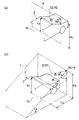
図1〜図3に示すように、この車種判別装置は、車両2が通過する通路たとえば高速道路の料金所入口や立体駐車場入口などの通路1(図では1車線で説明したが複数車線でも可)に設置されており、通路1の側部に1本の支柱1aを介して配置されて通過する車両(車体)2を検出する測定部3と、測定部3からの信号により車種を判別する演算判定部4と、演算判定部4の出力データを表示する表示装置5aおよび出力データを記録する記憶装置5bとを備えた記憶表示部5とで構成されている。
【0014】
(測定部)
この測定部3は、図3に示すように、第1検出部6および第2検出部7により構成されている。この第1検出部6には、投射波の一種であるレーザパルスからなる第1投射光S1を通路1を通過する車両2に向って上方から天井面および一方(支柱1a側)の側面5に照射し、車両2や路面1bに反射した第1反射光(反射波)R1を受光する第1投受光器21aと、第1投受光器21aの検出信号を測定部3から車両2の反射面までの距離データdに変換する第1距離演算部21bとを具備した第1レーザ距離センサ(第1距離センサ)21が設けられている。また、この第1投受光器21aにより、第1投射光S1の照射軌跡が、路面における通路(車長方向A,車両の進行方向)に対して垂直に交差するように所定周期でレーザスキャンを行う第1走査装置22と、第1投射光S1の走査角θ1を検出する第1走査角検出器23とが設けられている。
【0015】
なお、この実施の形態では、測定部3の第1検出部6と第2検出部7とを設置コストを考慮して一個所にまとめて設置したため、第1走査装置22により第1投射光S1の照射横断面fが路面1bに対してα゜傾斜するように設定している。しかし、照射横断面fは第2検出部7の照射軌跡と所定の距離以上はなれればよく、路面1bに対する傾斜角αは設定値により補正できるため路面に直角であっても、傾斜角があってもよく、第1検出部6と第2検出部7を別々に設置してもよい。またこの第1検出部1は、第2検出部7と同様にレーザスキャンされているため、検出目標となる車両2を、自動二輪などから区別して検出することができる。
【0016】
また、第1検出部6では、単に車両の有無が判断されればよいため、レーザセンサに代えて、設備コストを考慮すると、投射光の受光の断続を検出する近接スイッチなどの非接触式位置センサでもよい。さらに、車両の速度を検出できれば第1検出部6の機能を果たすことができるため、第1検出部6に代えて速度センサを設置することもできる。
【0017】
また第2検出部7には、レーザパルスからなる第2投射光S2を、通路1を通過する車両2に向って天井面および一方(支柱1a側)の側面5に照射し、車両2や路面1bに反射した第2反射光R2を受光する第2投受光器31aと、第2投受光器31aの検出信号を測定部3から車両2の反射面までの距離データdに変換する第2距離演算部31bからなる第2レーザ距離センサ(第2距離センサ)31が設けられている。また、この第2投受光器31aを走査して、第2投射光S2を照射軌跡が車両2の進行方向に対して垂直に交差し、かつ走査横断面eが路面1bに垂直になるように所定周期でレーザスキャンを行う第2走査装置32と、第2投射光S2の走査角θ2を検出する第2走査角検出器33とが設けられている。
【0018】
(演算判定部)
前記演算判定部4は、車高検知部11と車速演算部12と車高・車幅・車長演算部13と天井面決定部14と車種判別部15が具備されている。
【0019】
前記車高検知部11は、第1,第2距離演算部21b,31bからの距離データdと、走査角検出器23,33からの走査角データθとにより、測定部3の設定高さHsに基づいて車両2の反射面の高さ(車高)hを演算するものである。
すなわち、図4(a)に示すように、照射横断面eが路面1bに垂直な第2投射光S2の場合には、車高h2=Hs−d2×cosθ2で求められる。しかし、第1投射光S1は図4(b)に示すように、照射横断面fが路面に対してα゜傾斜しており、この場合には、検出された距離データd1を前記通路1の長さ方向の垂直座標面上での距離データd1′に補正すると、d1′=d1×cosθ1となり、実際の車高h2=Hs−d1′×sinα=Hs−d1×cosθ1×sinαにより補正して求めることができる。そして、この複数のスキャン分の演算結果を図示しないメモリに記憶させる。
【0020】
また車速演算部12は、車両2の前端間の距離、すなわち第1投射光S1と第2投射光S2により最初に車両を検出した位置間の水平距離(第1投射光S1の位置は検出高さh1により補正)Lsを、第1投射光S1と第2投射光S2により最初に車両を検出した時(路面より高い高さhを検出した時)の時間差(実際にはスキャン本数×スキャン周期)で除算して車両2の第1の車速データを求める。さらに車両2の後端間の距離、すなわち第1投射光S1と第2投射光S2により最後に車両を検出とした位置間の水平距離(第1投射光S1の位置は検出高さh1により補正)を、第1投射光S1と第2投射光S2により最後に車両を検出とした時(路面のみしか検出できなかった時)の時間差(実際にはスキャン本数とスキャン周期で求められた時間)で除算して車両2の第2の車速データを求める。そして、計測環境や設定条件などにより、第1の車速と第2の車速の平均値をとるか、第1の車速と第2の車速の一方を選択することにより、車両2の速度Vを決定する。
【0021】
なお、車速演算部12における他の速度検出方法として、スキャン周期を短くして細かく計測し、車両2の前端で車速を求める場合、前端部付近での数スキャン内のデータのうち、第1投射光S1と第2投射光S2の高さh1,h2が近い位置間で水平距離を求めればよい。車両2の後端で車速を求める場合も考え方は同じである。
【0022】
さらに車高・車幅・車長演算部13は、車速と第2投射光S2の走査タイミングに基づいて所定走査タイミング間の車両2の移動量(長さ)を、車長L=スキャン回数×スキャン周期×車速Vにより演算される。また車高は、車高データhのうち、最も高い値が選択される。さらに車幅Dは、図2(b)に示すように、各照射断面において、路面より高い左端の距離データをdL、その時の走査角をθLとし、また路面より高い右端の距離データをdRその時の走査角をθRとして車幅D=|dL×cosθL−dR×cosθR|で求めた最も長い値とする。
【0023】
前記天井面決定部14は、車高データhをもとに演算された車両2の平面部のうち、それが所定範囲内の高低差であり、かつその高さが一定値以上あり、車長方向Aに沿う長さが一定値以上あり、さらに最も車両2の前面に近い平面部が運転席天井面2aに特定される。
【0024】
すなわち、天井面が平面部であるかどうかの特定は、図5に示すように、まず車高検知部11によって演算された複数のスキャンによる車両2の高さデータhから車長方向のデータと幅方向のデータにおいて、[1]式を満たす平面部分を車両2の前側から順に探す。
【0025】
|H(I,j)-H(I,j+1)|<TH …[1]
ここで、I:行(車長方向の車高データh)
j:列(車幅方向の車高データh)
H(I,j):I行j列目の車高データh、
H(I,j+1):I行j+1列目の車高データh、
TH(Threshold):平面とみなすための高低差の許容範囲(しきい値)である。
【0026】
なお、ここで、図2(a)に示すように、距離データd1,d2と等しい値が側面2bで表れることも考えられるが、側面の場合は|H(I,j)-H(I,j+1)|≧THとなるので上記[1]式を満足せず、天井面か側面部であるかを判断することができる。
【0027】
そして、上記[1]式を一定の割合以上満足するデータ列が見つかると、この平面部分が[2]式を満足するかどうかを確認する。
TH Min<|Hv(I)-Hv(I+1)|<TH Max …[2]
TH Min:隣合う測定箇所の高低差の最小許容値
TH Max:隣合う測定箇所に高低差の最大許容値
Hv(I):I行目の車高データhの平均値
Hv(I+1):I+1行目の車高データhの平均値である。
このように[1]および[2]式を満足する平面部分を平面部として抽出する。
【0028】
そして、これら平面部のうち、高さが一定値以上あり、車長方向の長さがに一定値以上あるかどうかを演算し、これら条件を満足した平面部のうち、最も車両2の前側に近い部分を運転席天井面2aであると特定する。
【0029】
前記車種判別部15では、上記天井面決定部14の演算結果と、車高・車幅・車長演算部13により得られたデータにより、予め入力された車種データに基づいて車種判別を行う。
【0030】
たとえば1つの判別基準として、図10〜図14に示すように、運転席天井面2aの前後部に所定の車長L1,L3のボンネット部分やトランク部分などを有している。これらの各車種の平面部の値は、車種によって異なったしきい値を有しており、車種によって車長の範囲も決められている。さらに上記[1]および[2]式を満足しない運転席天井面2a以外では、天井面決定部14において、運転席天井面2aの前方の前部車体および後方の後部車体の長さL1,L3および高さhが演算され、前部車体と運転席天井面2aと後部車体の長さデータL1,L2,L3によって車種が判別される。なお、図12(ワンボックスタイプ)、図9(トラック)、図13(バス)に示す車両2(車体)についても同様に車種が判別される。
【0031】
ここで、車種によっては、運転席天井面2aにレーザパルスを反射しないサンルーフSが装備されている場合もあるが、この場合には車高データhが乱れる。そこで、図15に示すように、車高データh(計測データ列)のうちから最大高さを示す点の列を結んで直線に見做し(直線近似処理し)、天井面の勾配S(1,2,3,4)のうち、車高データhの乱れが発生している箇所が直線でかつ勾配、すなわち図ではS(3)が、下記の[3]式
TH Min<S(3)<TH Max …[3]
を満足する場合、天井面決定部2aがその部分をサンルーフSと判断する。これにより、この実施の形態によれば、サンルーフの有無に関係なく車種を特定することができる。
【0032】
次に、上記構成における車種判別装置における車種判別方法を図7〜図9のフローチャートに基づいて説明する。
1.図7に示すように、第1投受光器21aおよび第2投受光器31aから第1投射光S1および第2投射光S2がそれぞれ通路1に向けて照射され、第1反射光R1および第2反射光R2が検出される。そしてこれら検出信号が第1,第2距離演算部21b,31bで測定部3から車両2の反射面までの距離dが演算される。
【0033】
この動作を第1投受光器21および第2投受光器31で1ラインスキャンを完了まで行い、1ライン分の距離データが順次距離演算部24,34に記憶される。
【0034】
次いで図8に示すように、車高検知部11では、第1,第2距離演算部21a,31aおよび第1,第2走査角検出器23,33の検出信号が入力され、これらのデータから高さデータhが演算され、メモリに保存される。
【0035】
そして、車両前端部の検出において、第2検出部7からの高さデータh2がチェックされ、路面1bより高い部分(=車両)が検出されると、高さデータh2が車速演算部12に出力される。ついで、車高検知部11の第1検出部6の車高データh1がチェックされ、路面1bより高い部分(=車両)が検出されると、高さデータh1が車速演算部12に出力されメモリに保存される。同様に、車両の後端部も検出される。
【0036】
この車速演算部12では、第1,第2投射光S1,S2による車両2の前端間および後端間の水平距離と、第1,第2投射光S1,S2による検出時間差から車両2の速度Vを決定する。
【0037】
さらに、図9に示すように、車高・車幅・車長演算部13では、第2検出部7の検出データにより、車両2の車高hと車長Lと車幅Dが演算される。
次いで天井面決定部14では、高さデータhから高さが1定値以上あり、かつそれが平面で車長の長さ方向に沿って1定値以上あり、かつ最も車両2の前面に近い部分を運転席天井面2aと決定する。
【0038】
続いて、車種判別部15では、運転席天井面2aの前部車体の長さL1および後部車体の長さL3を演算するとともに、車長、車高、車幅の各データと車体ののL1,L2,L3より車種が判別される。
【0039】
このように上記実施の形態によれば、車種判別の特徴である平面部を検出して運転席天井部を特定し、運転席天井部の高さや広さや長さのデータと、運転席天井部の配置位置(前後のボンネットやトランク等を含めて)を考慮するとともに、車両の車高、車幅、車長のデータから車種を正確に特定することができる。
【0040】
また2つのレーザ距離センサを走査するだけで、必要な車両の平面部の抽出と運転席天井面2aの特定を行うことができ、装置構造を簡単にできるとともに、低コストで提供することができる。これにより、たとえば道路計画などの予備調査において、どのような車種の車両がどれだけの交通量を有しているかを自動的に調査することができ、道路計画に有効利用できる。
【0041】
なお、上記実施の形態では、距離センサにレーザ距離センサを使用したが、超音波距離センサであってもよい。
【0042】
【発明の効果】
以上に述べたごとく請求項1記載の車種判別方法によれば、第1検出部の非接触式位置センサと第2検出部の距離センサの検出信号の検出時間差と検出位置の水平距離から車両の速度を求めるとともに、車高データから求められた複数の平面部のうちの1つを、多種ある車両のうちで、特に特徴となる運転席天井面として特定し、運転席天井面のデータとその前後の車体の長さで車種を判別するので、簡単な操作で車種を正確に判別することができる。
【0043】
請求項2記載の車種判別方法によれば、第1検出部の速度検出センサにより車両の速度を求めるとともに、車高データから求められた複数の平面部のうちの1つを、多種ある車両のうちで特に特徴となる運転席天井面として特定し、運転席天井面のデータとその前後の車体の長さで車種を判別するので、簡単な操作で車種を正確に判別することができる。
【0044】
請求項3記載の車種判別方法によれば、第1検出部の距離センサと第2検出部の距離センサの車両の前端または後端を検出した検出位置の水平距離から車両の速度を求めるとともに、車高データから求められた複数の平面部のうちの1つを、多種ある車両のうちで、特に特徴となる運転席天井面として特定し、運転席天井面のデータとその前後の車体の長さで車種を判別するので、簡単な操作で車種を正確に判別することができる。
【0045】
請求項4記載の車種判別装置によれば、測定部の第1検出部および第2検出部から所定周期で通路横断方向に走査される投射波により、車両反射部までの距離を測定する。そして演算判定部で車高および車幅を演算し、車両の前端または後端を検出した検出位置の水平距離から車速を演算し、さらに車高データと車速データから車長を演算するとともに車両の平面部を抽出し、これら平面部のうちの1つを、多種ある車両のうちで特に特徴となる運転席天井面として特定されるので、運転席天井面のデータとその前後の車長データに基づいて車種を正確に判別することができ、簡単な構成で車種を正確に判別することができる。
請求項5記載の車種判別装置によれば、第1検出部と第2検出部とを一箇所にまとめて設置することにより、設置コストを低減することができる。
【図面の簡単な説明】
【図1】本発明にかかる車種判別装置の実施の形態を示す全体斜視図である。
【図2】(a)は同車種判別装置の検出状態を示す車両の横断面図、(b)は同車幅検出状態を示す正面図である。
【図3】同車種判別装置を示す構成図である。
【図4】(a)(b)は同車種判別装置による車高データの演算方法を示し、(a)は第2反射光の説明図、(b)は第1反射光の説明図である。
【図5】同車種判別装置による検出状態を示す全体の模式図である。
【図6】同車種判別装置による検出状態を示す側面の模式図である。
【図7】同車種判別装置の判別手順を示すフローチャートである。
【図8】同車種判別装置の判別手順を示すフローチャートである。
【図9】同車種判別装置の判別手順を示すフローチャートである。
【図10】同車種判別装置によるセダンタイプの判別基準の車体を示す説明図である。
【図11】同車種判別装置によるバンタイプの判別基準の車体を示す説明図である。
【図12】同車種判別装置によるワンボックスタイプの判別基準の車体を示す説明図である。
【図13】同車種判別装置によるトラックタイプの判別基準の車体を示す説明図である。
【図14】同車種判別装置によるバスタイプの判別基準の車体を示す説明図である。
【図15】同車種判別装置によるサンルーフを有する車体の判別状態を示す説明図である。
【符号の説明】
S1,S2 第1,第2投射光
R1,R2 第1,第2反射光
1 通路
1a 支柱
1b 路面
2 車体
3 測定部
4 演算判定部
5 記憶表示部
6 第1検出部
7 第2検出部
11 車高検知部
12 速度演算部
13 車高・車幅・車長演算部
14 天井面決定部
15 車種判別部
21 第1レーザ距離センサ
21a 第1投受光器
21b 第1距離演算部
22 第1走査装置
23 第1走査角検出器
31 第2レーザ距離センサ
31a 第2投受光器
31b 第2距離演算部
32 第2走査装置
33 第2走査角検出器[0001]
BACKGROUND OF THE INVENTION
The present invention relates to a vehicle type determination method and apparatus for determining a vehicle type passing through a passage.
[0002]
[Prior art]
In general, in order to measure the number of vehicles passing through a road, a method is used in which ultrasonic waves or microwaves are used, or imaging is performed using camera images.
[0003]
[Problems to be solved by the invention]
By the way, in recent years, it has become necessary to determine how many types of vehicles pass the road.
[0004]
However, in the above measurement method, there is no problem in measuring the number of vehicles passing through the road, but there is a problem that it is very difficult to discriminate the vehicle type.
The present invention relates to a vehicle type discriminating method and apparatus capable of solving the above-described problems and accurately discriminating a vehicle type with a simple configuration.
[0005]
[Means for Solving the Problems]
In order to solve the above-mentioned problem, the vehicle type identification method according to
In the measurement unit,
The non-contact position sensor provided in the first detection unit detects the passage of the vehicle,
The crossing direction of the passage in a predetermined cycle by irradiating the projection wave from above the vehicle from the distance sensor provided in the second detection portion at a position away from the detection position by the first detection portion in front or behind the passage. To detect the reflected wave and the scanning angle of the projected wave, to calculate the distance from the second detection unit to the reflective surface of the vehicle,
In the calculation determination unit,
The vehicle height and the vehicle width are calculated from the distance obtained by the second detector and the scanning angle, and the vehicle speed is calculated from the detection time difference between the distance sensor and the non-contact position sensor and the horizontal distance of the detection position. The vehicle length is calculated from the vehicle height data and the speed of the vehicle, and the plane portion of the vehicle is extracted from the vehicle height data. The plane portion of the vehicle has a height difference within a predetermined range and a certain level or more. the length of the height and the vehicle length direction are more than a certain, and most one of the planar portions specific to the driver's seat ceiling surface close to the front of the vehicle, vehicle type by the data in the vehicle length of the driver's seat ceiling surface and its front and rear Is determined.
According to the above configuration, the vehicle speed is obtained from the detection time difference between the detection signals of the non-contact position sensor of the first detection unit and the distance sensor of the second detection unit and the horizontal distance of the detection position, and is obtained from the vehicle height data. In addition, one of the plurality of plane portions is specified as a driver seat ceiling surface that is particularly characteristic among various vehicles, and the vehicle type is determined by data on the driver seat ceiling surface and the length of the vehicle body before and after the driver seat ceiling surface. The vehicle type can be accurately determined with a simple operation.
[0006]
In the vehicle type identification method according to
In the measurement unit,
The speed detection sensor provided in the first detection unit detects the speed of the vehicle,
A second wave is detected by irradiating a projected wave from above the vehicle from a distance sensor provided in the second detector and scanning in the transverse direction of the passage at a predetermined cycle, and detecting the reflected wave and the scanning angle of the projected wave. Calculate the distance from the vehicle to the reflective surface of the vehicle,
In the calculation determination unit,
The vehicle height and the vehicle width are calculated from the distance and the scanning angle obtained by the second detection unit, the vehicle length is calculated from the vehicle height data and the vehicle speed, and the vehicle height is calculated from the vehicle height data. One of the plane portions of the plane portion having a height difference within a predetermined range, having a certain height or more and a length in the vehicle length direction, and closest to the front surface of the vehicle. the identified in the driver's seat ceiling surface, it is to determine the vehicle type by the data in the vehicle length of the driver's seat ceiling surface and its front and rear.
According to the above configuration, the speed of the vehicle is obtained by the speed detection sensor of the first detection unit, and one of the plurality of plane parts obtained from the vehicle height data is particularly characteristic among various vehicles. Since it is specified as the driver's seat ceiling surface and the vehicle type is determined based on the data on the driver's seat ceiling surface and the length of the vehicle body before and after the data, the vehicle type can be accurately determined with a simple operation.
[0007]
In the vehicle type identification method according to
In the measurement unit,
The first detection unit irradiates the vehicle with a first projection wave from above the vehicle, scans the vehicle in the transverse direction of the passage at a predetermined cycle, and detects the scanning angle of the first projection wave to perform the first detection. Calculate the distance from the vehicle to the reflective surface of the vehicle,
The second detection wave is irradiated from the upper side of the vehicle to the vehicle at a predetermined distance from the first detection wave irradiation position to the front or rear of the passage from the second detection unit to the vehicle at a predetermined cycle in the transverse direction of the passage. And scanning the reflected wave and the scanning angle of the second projection wave to calculate the distance from the second detection unit to the reflecting surface of the vehicle,
In the operation judgment unit,
Calculating a vehicle height and a vehicle width from the distance between the scanning angle obtained from the first detector and the second detector calculates the vehicle speed from the horizontal distance detection position detected the front end or rear end of the vehicle, The vehicle length is calculated from the vehicle height data and the vehicle speed, and the plane portion of the vehicle is extracted from the vehicle height data. The plane portion has a height difference within a predetermined range and a certain height or more. A plane portion that is longer than a certain length in the vehicle length direction and that is closest to the front of the vehicle is identified as the ceiling surface of the driver's seat, and the vehicle type is determined based on the data on the driver's seat ceiling surface and the vehicle length before and after that. .
According to the above configuration, the vehicle speed is obtained from the horizontal distance of the detection position where the front end or the rear end of the vehicle of the distance sensor of the first detection unit and the distance sensor of the second detection unit is detected, and is obtained from the vehicle height data. In addition, one of the plurality of plane portions is specified as a driver seat ceiling surface that is particularly characteristic among various vehicles, and the vehicle type is determined by data on the driver seat ceiling surface and the length of the vehicle body before and after the driver seat ceiling surface. The vehicle type can be accurately determined with a simple operation.
[0008]
The vehicle type discriminating device according to
A first distance sensor for detecting a distance to the vehicle by irradiating a vehicle passing through the passage with a first projection wave from above the vehicle to the first detection unit of the measurement unit, and passing the first projection wave across the passage A scanning device that scans in the direction with a predetermined period, a scanning angle detector that detects a scanning angle of the first projection wave, and a first distance calculation unit that calculates the distance from the measurement unit to the reflecting surface of the vehicle,
The second detection wave is irradiated to the vehicle passing through the passage from the second detection unit to the vehicle at a position away from the irradiation position of the first projection wave in the front-rear direction by the second detection unit of the measurement unit. A second distance sensor that detects the distance of the second projection wave, a scanning device that scans the second projected wave in the transverse direction of the passage at a predetermined period, a scanning angle detector that detects a scanning angle of the second projected wave, and a vehicle from the measurement unit A second distance calculation unit that calculates the distance to the reflective surface of
In the calculation judgment part,
A vehicle height detection unit that calculates the vehicle height from detection data of the first detection unit and the second detection unit, a vehicle speed calculation unit that calculates the vehicle speed from the horizontal distance of the detection position where the front end or the rear end of the vehicle is detected, extraction with calculates the width and height, vehicle width, vehicle length calculator for calculating a vehicle length from the vehicle speed data of the vehicle height data and the vehicle speed calculating section of the vehicle height detecting unit, the flat portion from the vehicle height data and, among the flat portion, with a height difference within a predetermined range, and there the length of the predetermined or greater height and vehicle length direction is equal to or greater than a predetermined, and the most one plane portion close to the front of the vehicle on the driver's seat ceiling surface A ceiling surface determination unit to be identified, and a vehicle type determination unit that determines a vehicle type based on data on the ceiling surface of the driver's seat and the vehicle length before and after the ceiling surface.
[0009]
According to the said structure, the distance to a vehicle reflection part is measured by the projection wave scanned in a channel crossing direction by the predetermined period from the 1st detection part and 2nd detection part of a measurement part. Then, the vehicle height and vehicle width are calculated by the calculation determination unit, the vehicle speed is calculated from the horizontal distance of the detected position where the front end or the rear end of the vehicle is detected, the vehicle length is calculated from the vehicle height data and the vehicle speed data, and the vehicle Since a plane portion is extracted and one of these plane portions is determined as a driver seat ceiling surface that is particularly characteristic among various vehicles, it is based on data on the driver seat ceiling surface and vehicle length data before and after that. The vehicle type can be accurately determined, and the vehicle type can be accurately determined with a simple configuration.
[0010]
According to a fifth aspect of the present invention, there is provided the vehicle type identification device according to the fourth aspect, wherein the first detection unit and the side of the passage are disposed at positions where the projection wave is irradiated from the upper side toward the vehicle toward the ceiling surface and one side surface. The measurement part which consists of a 2nd detection part is arrange | positioned.
According to the above configuration, the installation cost can be reduced by installing the first detection unit and the second detection unit together in one place.
[0012]
DETAILED DESCRIPTION OF THE INVENTION
DESCRIPTION OF EMBODIMENTS Hereinafter, an embodiment of a vehicle type identification device according to the present invention will be described with reference to FIGS.
[0013]
As shown in FIGS. 1 to 3, this vehicle type identification device is used for a
[0014]
(Measurement part)
As shown in FIG. 3, the
[0015]
In this embodiment, since the first detection unit 6 and the
[0016]
In addition, since the first detection unit 6 simply needs to determine the presence or absence of the vehicle, in consideration of the equipment cost instead of the laser sensor, a non-contact position such as a proximity switch that detects intermittent light reception of the projection light is used. It may be a sensor. Furthermore, since the function of the 1st detection part 6 can be fulfilled if the speed of a vehicle can be detected, it can replace with the 1st detection part 6 and a speed sensor can also be installed.
[0017]
The
[0018]
(Calculation judgment part)
The
[0019]
The vehicle
That is, as shown in FIG. 4A, when the irradiation cross section e is the second projection light S2 perpendicular to the
[0020]
The vehicle
[0021]
In addition, as another speed detection method in the vehicle
[0022]
Further, the vehicle height / vehicle width / vehicle
[0023]
The ceiling
[0024]
That is, as shown in FIG. 5, first, whether or not the ceiling surface is a plane portion is determined by using vehicle height data h based on a plurality of scans calculated by the vehicle
[0025]
| H (I, j) -H (I, j + 1) | <TH (1)
Where I: line (vehicle height data h in the vehicle length direction)
j: Row (vehicle height data h in the vehicle width direction)
H (I, j): Vehicle height data h in I row and j column
H (I, j + 1): vehicle height data h of I row j + 1 column
TH (Threshold): This is an allowable range (threshold value) of height difference for considering a plane.
[0026]
Here, as shown in FIG. 2A, a value equal to the distance data d 1 , d 2 may appear on the
[0027]
When a data string satisfying the above-mentioned formula [1] at a certain rate or more is found, it is confirmed whether or not this plane portion satisfies the formula [2].
TH Min <| Hv (I) -Hv (I + 1) | <TH Max… [2]
TH Min: Minimum allowable height difference between adjacent measurement points TH Max: Maximum allowable height difference between adjacent measurement points
Hv (I): Average value of vehicle height data h on line I
Hv (I + 1): The average value of the vehicle height data h in the I + 1th row.
In this way, a plane portion satisfying the expressions [1] and [2] is extracted as a plane portion.
[0028]
And among these plane parts, it is calculated whether the height is a certain value or more and the length in the vehicle length direction is more than a certain value, and among the plane parts satisfying these conditions, the most front side of the
[0029]
The vehicle
[0030]
For example, as one discrimination criterion, as shown in FIGS. 10 to 14, a bonnet portion and a trunk portion of predetermined vehicle lengths L1 and L3 are provided at the front and rear portions of the driver's
[0031]
Here, depending on the vehicle type, there may be a sunroof S that does not reflect the laser pulse on the driver's
TH Min <S (3) <TH Max… [3]
Is satisfied, the ceiling
[0032]
Next, a vehicle type identification method in the vehicle type identification device having the above configuration will be described based on the flowcharts of FIGS.
1. As shown in FIG. 7, the first projection light S1 and the second projection light S2 are irradiated toward the
[0033]
This operation is performed until one line scan is completed by the first light emitter /
[0034]
Next, as shown in FIG. 8, in the vehicle
[0035]
In detecting the front end of the vehicle, the height data h 2 from the
[0036]
In the vehicle
[0037]
Further, as shown in FIG. 9, the vehicle height / vehicle width / vehicle
Next, the ceiling
[0038]
Subsequently, the vehicle
[0039]
As described above, according to the embodiment, the driver seat ceiling is identified by detecting the plane portion, which is a feature of vehicle type discrimination, and the height, width and length data of the driver seat ceiling, and the driver seat ceiling The vehicle type can be accurately identified from the vehicle height, width and length data of the vehicle.
[0040]
Further, by simply scanning the two laser distance sensors, it is possible to extract a necessary plane portion of the vehicle and specify the driver's
[0041]
In the above embodiment, the laser distance sensor is used as the distance sensor, but an ultrasonic distance sensor may be used.
[0042]
【The invention's effect】
As described above, according to the vehicle type identification method of the first aspect , the detection time difference between the detection signals of the non-contact type position sensor of the first detection unit and the distance sensor of the second detection unit and the horizontal distance of the detection position can be used. In addition to obtaining the speed, one of a plurality of plane portions obtained from the vehicle height data is specified as a particularly characteristic driver's seat ceiling surface among various vehicles, and the data on the driver's seat ceiling surface and its Since the vehicle type is determined by the length of the front and rear vehicle bodies, the vehicle type can be accurately determined by a simple operation.
[0043]
According to the vehicle type identification method of the second aspect, the speed of the vehicle is obtained by the speed detection sensor of the first detection unit, and one of the plurality of plane parts obtained from the vehicle height data is obtained from a variety of vehicles. Among them, the driver's seat ceiling surface, which is a special feature, is specified, and the vehicle type is determined based on the data on the driver's seat ceiling surface and the length of the vehicle body before and after the driver's seat ceiling surface.
[0044]
According to the vehicle type identification method of
[0045]
According to the vehicle type discriminating device of the fourth aspect, the distance to the vehicle reflecting portion is measured by the projection wave scanned in the passage crossing direction at a predetermined cycle from the first detecting portion and the second detecting portion of the measuring portion. Then, the vehicle height and vehicle width are calculated by the calculation determination unit, the vehicle speed is calculated from the horizontal distance of the detected position where the front end or the rear end of the vehicle is detected, the vehicle length is calculated from the vehicle height data and the vehicle speed data, and the vehicle extracting the flat portions, one of these flat parts, particularly identified as the driver's seat ceiling surface which is a feature among the multi-species certain vehicle, data of the driver's seat ceiling surface and its front and rear vehicle length data The vehicle type can be accurately determined based on the above, and the vehicle type can be accurately determined with a simple configuration.
According to the vehicle type identification device of the fifth aspect, the installation cost can be reduced by installing the first detection unit and the second detection unit together in one place.
[Brief description of the drawings]
FIG. 1 is an overall perspective view showing an embodiment of a vehicle type identification device according to the present invention.
FIG. 2A is a cross-sectional view of a vehicle showing a detection state of the vehicle type discrimination device, and FIG. 2B is a front view showing a vehicle width detection state.
FIG. 3 is a configuration diagram showing the vehicle type discrimination device.
FIGS. 4A and 4B show a vehicle height data calculation method by the vehicle type discriminating apparatus, FIG. 4A is an explanatory diagram of second reflected light, and FIG. 4B is an explanatory diagram of first reflected light; .
FIG. 5 is an overall schematic diagram showing a detection state by the vehicle type discrimination device.
FIG. 6 is a schematic side view showing a detection state by the vehicle type identification device.
FIG. 7 is a flowchart showing a discrimination procedure of the vehicle type discrimination device.
FIG. 8 is a flowchart showing a discrimination procedure of the vehicle type discrimination device.
FIG. 9 is a flowchart showing a discrimination procedure of the vehicle type discrimination device.
FIG. 10 is an explanatory diagram showing a sedan type discrimination reference vehicle body by the vehicle type discrimination device.
FIG. 11 is an explanatory view showing a vehicle body of a van type discrimination criterion by the vehicle type discrimination device.
FIG. 12 is an explanatory view showing a one-box type discrimination reference vehicle body by the vehicle type discrimination device.
FIG. 13 is an explanatory view showing a vehicle body of a track type discrimination reference by the vehicle type discrimination device.
FIG. 14 is an explanatory view showing a vehicle body of a bus type discrimination reference by the vehicle type discrimination device.
FIG. 15 is an explanatory view showing a discrimination state of a vehicle body having a sunroof by the vehicle type discrimination device.
[Explanation of symbols]
S1, S2 First and second projection light R1, R2 First and second reflected
Claims (5)
前記測定部で、
第1検出部に設けられた非接触式位置センサにより、車両の通過を検出し、
前記第1検出部による検出位置から通路の前方または後方に所定距離離れた位置で、第2検出部に設けられた距離センサから投射波を車両の上方から照射して所定周期で通路の横断方向に走査するとともに、その反射波と投射波の走査角とを検出して、第2検出部から車両の反射面までの距離を演算し、
前記演算判定部で、
第2検出部で得られた距離と前記走査角から車高と車幅とを演算し、前記距離センサと前記非接触式位置センサの検出時間差と、検出位置の水平距離から車両の速度を演算し、前記車高データと車両の速度から車長を演算し、さらに前記車高データから車両の平面部を抽出し、当該車両の平面部のうち、所定範囲内の高低差で、かつ一定以上の高さと車長方向の長さが一定以上あり、かつ最も車両の前面に近い平面部の1つを運転席天井面に特定し、当該運転席天井面とその前後の車長のデータにより車種を判定する
ことを特徴とする車種判別方法。 In determining the vehicle type of the vehicle passing through the passage by the measurement unit including the first detection unit and the second detection unit and the calculation determination unit,
In the measurement unit,
The non-contact position sensor provided in the first detection unit detects the passage of the vehicle,
The crossing direction of the passage in a predetermined cycle by irradiating the projection wave from above the vehicle from the distance sensor provided in the second detection portion at a position away from the detection position by the first detection portion in front or behind the passage. To detect the reflected wave and the scanning angle of the projected wave, to calculate the distance from the second detection unit to the reflective surface of the vehicle,
In the calculation determination unit,
The vehicle height and the vehicle width are calculated from the distance obtained by the second detector and the scanning angle, and the vehicle speed is calculated from the detection time difference between the distance sensor and the non-contact position sensor and the horizontal distance of the detection position. The vehicle length is calculated from the vehicle height data and the speed of the vehicle, and the plane portion of the vehicle is extracted from the vehicle height data. The plane portion of the vehicle has a height difference within a predetermined range and a certain level or more. the length of the height and the vehicle length direction are more than a certain, and most one of the planar portions specific to the driver's seat ceiling surface close to the front of the vehicle, vehicle type by the data in the vehicle length of the driver's seat ceiling surface and its front and rear A vehicle type identification method characterized by determining
前記測定部で、
第1検出部に設けられた速度検出センサにより車両の速度を検出し、
第2検出部に設けられた距離センサから投射波を車両の上方から照射して所定周期で通路の横断方向に走査するとともに、その反射波と投射波の走査角とを検出して第2検出部から車両の反射面までの距離を演算し、
前記演算判定部で、
第2検出部で得られた前記距離と前記走査角から車高と車幅とを演算するとともに、前記車高データと車両の速度から車両の車長を演算し、さらに前記車高データから車両の平面部を抽出し、当該平面部のうち、所定範囲内の高低差で、かつ一定以上の高さと車長方向の長さが一定以上あり、かつ最も車両の前面に近い平面部の1つを運転席天井面に特定し、当該運転席天井面とその前後の車長のデータにより車種を判定する
ことを特徴とする車種判別方法。 In determining the vehicle type of the vehicle passing through the passage by the measurement unit including the first detection unit and the second detection unit and the calculation determination unit,
In the measurement unit,
The speed detection sensor provided in the first detection unit detects the speed of the vehicle,
A second wave is detected by irradiating a projected wave from above the vehicle from a distance sensor provided in the second detector and scanning in the transverse direction of the passage at a predetermined cycle, and detecting the reflected wave and the scanning angle of the projected wave. Calculate the distance from the vehicle to the reflective surface of the vehicle,
In the calculation determination unit,
The vehicle height and the vehicle width are calculated from the distance and the scanning angle obtained by the second detection unit, the vehicle length is calculated from the vehicle height data and the vehicle speed, and the vehicle height is calculated from the vehicle height data. One of the plane portions of the plane portion having a height difference within a predetermined range, having a certain height or more and a length in the vehicle length direction, and closest to the front surface of the vehicle. the operation specified in the seat ceiling surface, vehicle type identification method characterized by determining the vehicle type by the data in the vehicle length of the driver's seat ceiling surface and its front and rear.
前記測定部で、
第1検出部から車両に対して第1投射波を車両の上方から照射して、所定周期で通路の横断方向に走査するとともに、当該第1投射波の走査角を検出して、第1検出部から車両の反射面までの距離を演算し、
第2検出部から車両に対して、第1投射波の照射位置から通路の前方または後方に所定距離離れた位置で、車両の上方から第2投射波を照射して通路の横断方向に所定周期で走査するとともに、その反射波と第2投射波の走査角とを検出して、第2検出部から車両の反射面までの距離を演算し、
演算判定部で、
第1検出部および第2検出部から得られた前記距離と前記走査角から車高と車幅とを演算し、車両の前端または後端を検出した検出位置の水平距離から車速を演算し、車高データと車両の速度から車両の車長を演算するとともに、前記車高データから車両の平面部を抽出し、当該平面部のうち、所定範囲内の高低差で、かつ一定以上の高さと車長方向の長さが一定以上あり、かつ最も車両の前面に近い平面部を運転席天井面に特定し、当該運転席天井面とその前後の車長のデータにより車種を判定する
ことを特徴とする車種判別方法。 When determining the vehicle type of the vehicle passing through the passage by the measurement unit including the first detection unit and the second detection unit and the calculation determination unit,
In the measurement unit,
The first detection unit irradiates the vehicle with a first projection wave from above the vehicle, scans the vehicle in the transverse direction of the passage at a predetermined cycle, and detects the scanning angle of the first projection wave to perform the first detection. Calculate the distance from the vehicle to the reflective surface of the vehicle,
The second detection wave is irradiated from the upper side of the vehicle to the vehicle at a predetermined distance from the first detection wave irradiation position to the front or rear of the passage from the second detection unit to the vehicle at a predetermined cycle in the transverse direction of the passage. And scanning the reflected wave and the scanning angle of the second projection wave to calculate the distance from the second detection unit to the reflecting surface of the vehicle,
In the operation judgment unit,
Calculating a vehicle height and a vehicle width from the distance between the scanning angle obtained from the first detector and the second detector calculates the vehicle speed from the horizontal distance detection position detected the front end or rear end of the vehicle, The vehicle length is calculated from the vehicle height data and the vehicle speed, and the plane portion of the vehicle is extracted from the vehicle height data. The plane portion has a height difference within a predetermined range and a certain height or more. The length in the vehicle length direction is more than a certain value, and the flat part closest to the front of the vehicle is specified as the ceiling surface of the driver's seat, and the vehicle type is determined based on the data on the ceiling surface of the driver's seat and the vehicle length before and after the driver's seat. Car model identification method.
測定部の第1検出部に、通路を通過する車両に対して車両の上方から第1投射波を照射し車両までの距離を検出する第1距離センサと、前記第1投射波を通路の横断方向に所定周期で走査する走査装置と、前記第1投射波の走査角を検出する走査角検出器と、測定部から車両の反射面までの距離を演算する第1距離演算部とを設け、
測定部の第2検出部に、第1投射波の照射位置から前後方向に所定距離離れた位置で、第2検出部から通路を通過する車両に対して第2投射波を照射して車両までの距離を検出する第2距離センサと、第2投射波を通路の横断方向に所定周期で走査する走査装置と、第2投射波の走査角を検出する走査角検出器と、測定部から車両の反射面までの距離を演算する第2距離演算部とを設け、
演算判定部に、
第1検出部および第2検出部の検出データから、車高を演算する車高検知部と、車両の前端または後端を検出した検出位置の水平距離から車速を演算する車速演算部と、車幅を演算するとともに、前記車高検知部の車高データと前記車速演算部の車速データから車長を演算する車高・車幅・車長演算部と、前記車高データから平面部を抽出し、当該平面部のうち、所定範囲内の高低差で、かつ一定以上の高さと車長方向の長さが一定以上あり、かつ最も車両の前面に近い1つの平面部を運転席天井面に特定する天井面決定部と、前記運転席天井面とその前後の車長のデータにより車種を判定する車種判別部とを具備した
ことを特徴とする車種判別装置。 A vehicle type discriminating device that determines a vehicle type of a vehicle passing through a passage by a measurement unit including a first detection unit and a second detection unit, and a calculation determination unit,
A first distance sensor for detecting a distance to the vehicle by irradiating a vehicle passing through the passage with a first projection wave from above the vehicle to the first detection unit of the measurement unit, and passing the first projection wave across the passage A scanning device that scans in the direction with a predetermined period, a scanning angle detector that detects a scanning angle of the first projection wave, and a first distance calculation unit that calculates the distance from the measurement unit to the reflecting surface of the vehicle,
The second detection wave is irradiated to the vehicle passing through the passage from the second detection unit to the vehicle at a position away from the irradiation position of the first projection wave in the front-rear direction by the second detection unit of the measurement unit. A second distance sensor that detects the distance of the second projection wave, a scanning device that scans the second projected wave in the transverse direction of the passage at a predetermined period, a scanning angle detector that detects a scanning angle of the second projected wave, and a vehicle from the measurement unit A second distance calculation unit that calculates the distance to the reflective surface of
In the calculation judgment part,
A vehicle height detection unit that calculates the vehicle height from detection data of the first detection unit and the second detection unit, a vehicle speed calculation unit that calculates the vehicle speed from the horizontal distance of the detection position where the front end or the rear end of the vehicle is detected, extraction with calculates the width and height, vehicle width, vehicle length calculator for calculating a vehicle length from the vehicle speed data of the vehicle height data and the vehicle speed calculating section of the vehicle height detecting unit, the flat portion from the vehicle height data and, among the flat portion, with a height difference within a predetermined range, and there the length of the predetermined or greater height and vehicle length direction is equal to or greater than a predetermined, and the most one plane portion close to the front of the vehicle on the driver's seat ceiling surface A vehicle type discriminating apparatus comprising: a ceiling surface determining unit to be identified; and a vehicle type discriminating unit that discriminates a vehicle type based on data on the ceiling surface of the driver's seat and a vehicle length before and after the ceiling surface.
ことを特徴とする請求項4記載の車種判別装置。 The measurement part which consists of the 1st detection part and the 2nd detection part has been arranged in the position which irradiates a projection wave to a ceiling surface and one side from the upper part toward the vehicles in the side part of a passage. 4. The vehicle type identification device according to 4.
Priority Applications (1)
| Application Number | Priority Date | Filing Date | Title |
|---|---|---|---|
| JP2000139289A JP4544698B2 (en) | 2000-05-12 | 2000-05-12 | Vehicle type identification method and apparatus |
Applications Claiming Priority (1)
| Application Number | Priority Date | Filing Date | Title |
|---|---|---|---|
| JP2000139289A JP4544698B2 (en) | 2000-05-12 | 2000-05-12 | Vehicle type identification method and apparatus |
Publications (2)
| Publication Number | Publication Date |
|---|---|
| JP2001319290A JP2001319290A (en) | 2001-11-16 |
| JP4544698B2 true JP4544698B2 (en) | 2010-09-15 |
Family
ID=18646767
Family Applications (1)
| Application Number | Title | Priority Date | Filing Date |
|---|---|---|---|
| JP2000139289A Expired - Fee Related JP4544698B2 (en) | 2000-05-12 | 2000-05-12 | Vehicle type identification method and apparatus |
Country Status (1)
| Country | Link |
|---|---|
| JP (1) | JP4544698B2 (en) |
Families Citing this family (20)
| Publication number | Priority date | Publication date | Assignee | Title |
|---|---|---|---|---|
| JP3997837B2 (en) * | 2002-05-27 | 2007-10-24 | 株式会社デンソー | In-vehicle radar device, program |
| KR100625678B1 (en) * | 2004-11-01 | 2006-09-20 | 하이테콤시스템(주) | Vehicle detection system |
| JP4766269B2 (en) * | 2007-03-06 | 2011-09-07 | 株式会社安川電機 | Object detection method, object detection apparatus, and robot equipped with the same |
| JP5303873B2 (en) * | 2007-06-13 | 2013-10-02 | 株式会社Ihi | Vehicle shape measuring method and apparatus |
| JP5558077B2 (en) * | 2009-10-30 | 2014-07-23 | 三菱電機株式会社 | Vehicle detection device and toll charge system |
| JP5429565B2 (en) * | 2010-03-31 | 2014-02-26 | マツダ株式会社 | Vehicle height detection device |
| KR101296133B1 (en) * | 2011-09-05 | 2013-08-19 | (주)인펙비전 | classifing system for vehicle's type using laser distance sensor |
| JP6007395B2 (en) * | 2012-03-13 | 2016-10-12 | 株式会社創発システム研究所 | Traffic detection system |
| JP6340159B2 (en) * | 2012-05-11 | 2018-06-06 | 日本信号株式会社 | Vehicle type discrimination system by distance measurement sensor |
| KR101415142B1 (en) | 2013-04-18 | 2014-07-04 | (주)유에이종합통신 | Vehicle auto inspection system |
| JP6090190B2 (en) * | 2014-02-06 | 2017-03-08 | オムロン株式会社 | Mobile management device |
| JP5936649B2 (en) * | 2014-06-04 | 2016-06-22 | 三菱電機株式会社 | Vehicle detection device and toll charge system |
| JP2017096792A (en) * | 2015-11-25 | 2017-06-01 | 株式会社デンソーウェーブ | Traffic volume measuring device |
| CN107403555A (en) * | 2017-08-30 | 2017-11-28 | 中交第二航务工程勘察设计院有限公司 | A kind of highway overload remediation system and method |
| US12198268B2 (en) | 2020-03-31 | 2025-01-14 | Pioneer Corporation | Information processing device |
| CN114690257B (en) * | 2020-12-31 | 2026-02-10 | 同方威视技术股份有限公司 | Vehicle safety inspection system and safety inspection methods |
| CN114740490A (en) * | 2021-01-07 | 2022-07-12 | 杭州电子科技大学 | Continuous vehicle length measuring system based on single line laser radar and measuring method thereof |
| CN113124777B (en) * | 2021-04-20 | 2023-02-24 | 辽宁因泰立电子信息有限公司 | Vehicle size determination method, device and system and storage medium |
| WO2022259344A1 (en) * | 2021-06-08 | 2022-12-15 | 三菱電機株式会社 | Laser radar device |
| JP7676289B2 (en) * | 2021-10-08 | 2025-05-14 | 三菱重工機械システム株式会社 | Vehicle width measurement device, vehicle type discrimination device, vehicle type discrimination system, vehicle width measurement method and program |
Family Cites Families (1)
| Publication number | Priority date | Publication date | Assignee | Title |
|---|---|---|---|---|
| JP3363763B2 (en) * | 1997-12-19 | 2003-01-08 | 日立造船株式会社 | Vehicle type determination method and device |
-
2000
- 2000-05-12 JP JP2000139289A patent/JP4544698B2/en not_active Expired - Fee Related
Also Published As
| Publication number | Publication date |
|---|---|
| JP2001319290A (en) | 2001-11-16 |
Similar Documents
| Publication | Publication Date | Title |
|---|---|---|
| JP4544698B2 (en) | Vehicle type identification method and apparatus | |
| JP3206414B2 (en) | Vehicle type identification device | |
| CN114056324B (en) | Parking space recognition method and system based on data fusion | |
| US7633433B2 (en) | Method for detecting and documenting traffic violations at a traffic light | |
| CN101218127B (en) | Parking device | |
| JP4076196B2 (en) | Vehicle width measuring method and apparatus | |
| US20110013201A1 (en) | Device and method for measuring a parking space | |
| US10488517B2 (en) | Method and apparatus for recognizing vehicles using laser beam scanning | |
| JPH0830893A (en) | Vehicle type identification device and pay area management device | |
| CN111899562A (en) | Vehicle meeting prompting method for curve blind area | |
| WO2016143750A1 (en) | Vehicle parameter measurement device, vehicle type determination device, vehicle parameter measurement method, and program | |
| CN107229906A (en) | A kind of automobile overtaking's method for early warning based on units of variance model algorithm | |
| JPH11224397A (en) | Vehicle measuring device | |
| JP3636150B2 (en) | Judgment method of object type of reflector on runway | |
| US20150269428A1 (en) | Vehicle imaging system, vehicle imaging method and device, program, and recording medium | |
| JP4036119B2 (en) | Vehicle detection device and vehicle detection method | |
| JP4279302B2 (en) | Detection device | |
| US9784677B2 (en) | System and method for remotely sensing visible ray transmittance of vehicle window | |
| JP2019133241A (en) | Vehicle detection device and vehicle detection system | |
| JPH1123250A (en) | Object length measuring device, object monitoring device, vehicle length measuring device, and vehicle monitoring device | |
| JP3498532B2 (en) | Vehicle shape discriminator | |
| JPH08329398A (en) | Road detection device | |
| JP6777515B2 (en) | Vehicle type discrimination device, vehicle type discrimination method and program | |
| JP3539289B2 (en) | Vehicle type identification method and vehicle type identification device | |
| JP7676289B2 (en) | Vehicle width measurement device, vehicle type discrimination device, vehicle type discrimination system, vehicle width measurement method and program |
Legal Events
| Date | Code | Title | Description |
|---|---|---|---|
| A621 | Written request for application examination |
Free format text: JAPANESE INTERMEDIATE CODE: A621 Effective date: 20061221 |
|
| A131 | Notification of reasons for refusal |
Free format text: JAPANESE INTERMEDIATE CODE: A131 Effective date: 20091201 |
|
| A521 | Request for written amendment filed |
Free format text: JAPANESE INTERMEDIATE CODE: A523 Effective date: 20100201 |
|
| TRDD | Decision of grant or rejection written | ||
| A01 | Written decision to grant a patent or to grant a registration (utility model) |
Free format text: JAPANESE INTERMEDIATE CODE: A01 Effective date: 20100601 |
|
| A01 | Written decision to grant a patent or to grant a registration (utility model) |
Free format text: JAPANESE INTERMEDIATE CODE: A01 |
|
| A61 | First payment of annual fees (during grant procedure) |
Free format text: JAPANESE INTERMEDIATE CODE: A61 Effective date: 20100629 |
|
| FPAY | Renewal fee payment (event date is renewal date of database) |
Free format text: PAYMENT UNTIL: 20130709 Year of fee payment: 3 |
|
| FPAY | Renewal fee payment (event date is renewal date of database) |
Free format text: PAYMENT UNTIL: 20130709 Year of fee payment: 3 |
|
| LAPS | Cancellation because of no payment of annual fees |