JP4521996B2 - child seat - Google Patents
child seat Download PDFInfo
- Publication number
- JP4521996B2 JP4521996B2 JP2001006463A JP2001006463A JP4521996B2 JP 4521996 B2 JP4521996 B2 JP 4521996B2 JP 2001006463 A JP2001006463 A JP 2001006463A JP 2001006463 A JP2001006463 A JP 2001006463A JP 4521996 B2 JP4521996 B2 JP 4521996B2
- Authority
- JP
- Japan
- Prior art keywords
- angle meter
- seat
- child seat
- belt
- angle
- Prior art date
- Legal status (The legal status is an assumption and is not a legal conclusion. Google has not performed a legal analysis and makes no representation as to the accuracy of the status listed.)
- Expired - Lifetime
Links
Images



Landscapes
- Seats For Vehicles (AREA)
Description
【0001】
【発明の属する技術分野】
本発明は、ベルトガイド付きのチャイルドシートに関するもので、特に、そのチャイルドシートが自動車のシートに正しい角度で取付けられているかどうかを確認するための角度計を設置したチャイルドシートに関するものである。
【0002】
【従来の技術】
図8は従来より一般的に使用されているチャイルドシートとこれに設置された角度計の例を示している。Bがチャイルドシートであり、このチャイルドシートBは、乳幼児の座る座部1aとその座部につらなる背部1bとその座部1aにほぼ垂直若しくは外側へ鈍角に立ち上げられた左右の肘掛け部1cと同じくその背部1bにほぼ垂直若しくは外側へ鈍角に立ち上げられた左右の側部1dとからなる肘掛け付き椅子型のチャイルドシート本体1と、このチャイルドシート本体1を水平方向に回転可能および/またはリクライニング方向にスライドさせる台座3と、から構成される。そして、チャイルドシート本体1には、肩ベルト4及び腰ベルト5と、座部1aに乳幼児が座った状態で腹の部分に座部1aから立設している腹当て6とが備わっている。腹当て6にはバックルが設けられ、肩ベルト4及び腰ベルト5を挿通したタングがこのバックルに着脱可能に係止される。
このように、肩ベルト4と腰ベルト5とそして腹当て6とにより、乳幼児は安全かつ快適に保持される。
また、台座3にはチャイルドシート本体1との対向部に窪みを設けたベルト挿通部3aが設けられており、この挿通部3aに自動車のシートベルトを挿通することにより、チャイルドシートBを自動車シートに固定している。
さらに、チャイルドシート本体1は、その座部1aと背部1bと肘掛け部1cと側部1dとは一体成型されたシェル構造となっており、そして、ポリプロピレン樹脂のプラスチック成型品が多く使用されており、この一体成型されたシェル構造のチャイルドシート本体1の乳幼児の着座する表面は、シートクッション7で被われている。
【0003】
ところで、自動車シートの座面は水平に近い座面から急な傾斜角を持ったものまで自動車によりさまざまな角度となっているので、チャイルドシートをこのような自動車シートへ固定する場合、チャイルドシートが自動車シートに適正な角度で取り付けられているかどうかを確認する必要があることから、その確認を行えるように、従来より角度計を備えたチャイルドシートが提案されている。
図8ではこのような角度計をチャイルドシートに設けた例をいくつか示している。角度計8aはシート本体1の側部1dに設けた例であり、角度計8bは台座3に設けた例、角度計8cはシート本体の側部1dの上面に設けた例を示している。しかし、これらのどの角度計もその取付け位置が、自動車シート上へのチャイルドシートの固定時には見難い位置にある。
【0004】
一方、財団法人日本規格協会の定めたJISD0401−1996自動車用品―年少者保護装置(以下、JIS規格と略記する。)によれば、年少者保護装置の種類及び区分を規制しており、その種類は、「乳児用ベッド」、「幼児用シート」、「学童用シート」に分けられている。更に、その区分は、年少者(体重36kg以下の新生児、乳児、幼児、学童などの総称)の体重範囲によって、W1(10kg未満)、W2(9kg以上18kg以下)、W3(15kg以上25kg以下)、W4(22kg以上36kg以下)に分けられている。そして、図9に示すのが、区分W1に相当する後向き専用幼児用シートである。図において、Cが後向き専用幼児用シートW1である。このJIS規格区分W1に相当するチャイルドシートCには2つのタイプがあり、1つはその底面が円弧状をしていて、室内でのロッキングチェアとしての使用も可能なものであり、もう1つは底面が平らな面をしていて、安定に着座させておくタイプのものである。
【0005】
図9(a)および図9(b)はいずれもこの後向き専用幼児用シート(W1)Cを自動車シートに載置した状態の側面図を示している。図9(a)はチャイルドシート本体1の底面1eが円弧状をしている例で、このように底面1eが円弧状をしているために、自動車のシートSとの取付け角度は任意の角度に取付けてシートベルトで固定することができることとなる。したがって、2点鎖線のチャイルドシートC1のように水平に近い取り付け状態になることも起こりうるが、このような水平に近い取り付けは適正な取り付け角度ではない。
このように底面1eが円弧状をしているチャイルドシートC1では、任意の角度に取付け自由となるからこそ、適正な取り付け角度となっているかをその都度確認する必要がある。
【0006】
一方、図9(b)は、チャイルドシート本体1の底面1eが平らな面になっている例である。この場合、チャイルドシート本体1の底面1fは平面であり、また自動車シートSの座面S1も平面であるので、図9(a)とは違って自動車への取付け角度は一義的に決まってしまう。しかし、自動車シートSの座面S1は前述のようにその自動車によりさまざまな角度となっているので、図9(b)の2点鎖線のように水平に近い座面S2の場合もあり得、そうするとチャイルドシートCも2点鎖線のように水平に近いC2の位置などのように不適正な取付角度になってしまう。
このようにチャイルドシート本体1の底面1fが平らな面の場合も、適正な取り付け角度となっているかをその都度確認する必要がある。
このように、後向き専用のチャイルドシートCの2つのタイプのいずれについても、適正な取り付け角度となっているかを確認する必要があったが、従来のこのチャイルドシートCにおいても、図8のチャイルドシートBと同様、その載置時に角度計が見難い位置にあるために、チャイルドシートを自動車のシートへの載置時に角度計を視認することを忘れる場合が多かった。
【0007】
【発明が解決しようとする課題】
そこで、本発明の目的は上記課題を解決するもので、チャイルドシートを自動車のシートに取付ける際に、角度計の見落としを確実に防ぐことのできるチャイルドシートを提供することにある。
【0008】
【課題を解決するための手段】
前記の目的を達成するため、請求項1記載の発明は、チャイルドシート本体の自動車取付のために設けられたベルトガイドの肘掛け部に角度計を設置したチャイルドシートであって、シートベルトが前記肘掛け部とベルトガイド受けの間を通るように前記肘掛け部にベルトガイド受けを形成し、前記ベルトガイド受けの上部をガイドカバーで被せ、前記ベルトガイド受けと前記ガイドカバーとを前記肘掛け部に固定し、前記角度計が前記ベルトガイド受け内に回転可能に取付けられ、前記角度計は角度計ケースと該角度計ケース内に軸支される角度計ホイールより構成され、前記角度計ホイールの下部にバランサを付加したこと特徴とする。
一般に、前記区分W1に相当する後向き専用チャイルドシートには、自動車のシートにチャイルドシートを載置し固定するためにベルトガイドをチャイルドシート本体の左右一対の肘掛け部と本体の背部の裏側との合わせて3箇所に設けており、自動車のシートベルトをそれらのベルトガイドに経由させて自動車のシートへ固定する方式が一般的である。したがって、以上の構成によって、自動車のシートにチャイルドシートを取付ける際、シートベルトをベルトガイド経由させるためには必ずベルトガイドを見るので、ベルトガイドに設置されている角度計も必然的に見ることになり、角度計の見落としを防ぐことができる。
【0009】
角度計が角度計ケースと該角度計ケース内に軸支される角度計ホイールより構成されることにより、簡単な構造となり、低廉なコストと故障のない安定したものとなり、メンテナンスの必要もなく、安心して使用することができる。
【0010】
また、角度計を上から視認するので、この肘掛け部を見たときに自然と一緒に角度計も視認することができ、従って、見落としがなくなり、常に適正な角度で取付けることができる。
【0011】
また、角度計ホイールの下部にバランサを付加したことにより、チャイルドシートの載置作業時のチャイルドシートの揺れによる角度計の振れをはやく停止させることができるようになる。
【0013】
【発明の実施の形態】
以下、本発明の実施の形態を図面に基づいて説明する。
図1は、本発明の実施の形態を示したチャイルドシートの斜視図である。
同図において、チャイルドシートAは、図9のチャイルドシートCと同じで、自動車の進行方向に対して後向きに設置されるタイプのものである。このチャイルドシートAは、乳幼児の座る座部1aとその座部1aにつらなる背部1bと、その座部1aにほぼ垂直若しくは外側へ鈍角に立ち上げられた左右の肘掛け部1cと、同じくその背部1bにほぼ垂直若しくは外側へ鈍角に立ち上げられた左右の側部1dとからなるチャイルドシート本体1と、このチャイルドシート本体1のほぼ中央部近傍を支点9aとするハンドル9を備えている。ハンドル9は乳幼児をチャイルドシート本体1に乗せたまま運搬するときに把持して持ち運ぶためのものである。
さらに、肩ベルト及び腰ベルトと、乳幼児が座部1aに座った状態で腹の部分に座部1aから立設している腹当てと、を備えている。これらの肩ベルト、腰ベルト、腹当ては、図8と同様であり、図1では図面を見やすくするために図示していない。さらに、チャイルドシート本体1の乳幼児の着座する表面は、シートクッション7により被われている。
【0014】
このチャイルドシートAを自動車のシートS1に載置し固定する際は、自動車のシートベルト10を次のように引き回して自動車のシートS1へチャイルドシートAを固定している。すなわち、この方式は3点式シートベルトと呼称されているもので、シートベルト10の途中に挿通されているタング11aを持ってシートベルト10を引くと、シートベルト10が背ベルト10s側から引き出される。そこで、まずチャイルドシート本体1の背部1bに設けられたベルトガイド2cを通り、チャイルドシート本体1の前面へ回って、自動車のフロア側に固定されたベルトの先端に設けられたバックル11bにタング11aを差し込んで係止する。タング11aを挿通するシートベルト10の腰ベルト10w側は、肘掛け部1cに配設されたベルトガイド2aを通り、反対側の肘掛け部1cへ向かい、そこのベルトガイド2bを通り、自動車のアンカー(図示なし)に固定されている。
【0015】
そして、本発明によると、このチャイルドシート本体1の肘掛け部1cのベルトガイド2aに角度計8が設置されている。自動車シートの左右のどちら側にチャイルドシートを載置しても、角度確認を迅速に行えるように角度計8は左右両方のベルトガイド2a、2bに設置しておいてもよい。
このように本発明による角度計は自動車シートに固定の際、必ず目にするベルトガイドの中に設置されているために、視認性が向上すると共に、しかもあまり大きくないベルトガイドの中に設置するために、角度計の簡素化・小型化が行なえ、結果的にコストを抑える効果も生まれる。
【0016】
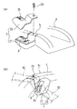
図2は図1のベルトガイド2aの拡大斜視図である。図2(a)はベルトガイドに角度計を設置した説明用の分解斜視図であり、図2(b)は、ベルトガイドに角度計を設置状態を別の角度から見た斜視図である。図2において、チャイルドシート本体1の肘掛け部1cに配設されたベルトガイド2は、ベルトガイド受け21とこのベルトガイド受け21の上に覆われるベルトカバー22とから構成されている。この肘掛け部1cにベルトガイド受け21を形成し、ベルトガイド受け21の上部をガイドカバー22で被せ、ベルトガイド受け21とガイドカバー22とをビス23で肘掛け部1cに固定している。そして、角度計8がベルトガイド受け21内に後述するように回転可能に取付けられている。
また、図2(b)によれば、角度計8がガイドカバー22の窓24より飛び出している。シートベルト(図2(b)の2点鎖線)10は、この肘掛け部1cとベルトガイド受け21の間を通り、次の行き先へ引き回されている。
このように、チャイルドシートAを自動車のシートSに載置し固定するとき、シートベルト10を必ずベルトガイド受け21に沿わして引き回すので、ベルトガイド2に設けられた角度計8も自然と視認するようになるので、角度計の見落としを確実に防ぐことができる。
【0017】
図3は、図2(b)のベルトガイド中央部を長さ方向に切断した断面図である。
図3において、角度計8は、角度計ケース81と角度計ホイール82より構成されている。角度計ケース81の軸孔81aに角度計ホイール82の軸82aを嵌め込み軸支状態となっている。従って、角度計ホイール82は、角度計ケース81に対して、軸82aを支点として回転可能となっている。
このように軸孔81aと軸82aによって軸支された角度計8は、ベルトガイド受け21に設けられた角度計受け台21aに載置され、ビス83によりねじ止めされて、ベルトガイド受け21に固定されている。すなわち、角度計受け台21aは、ベルトガイド受け21に設けられたリブである。リブの上面に角度計ケース81の下面の平らな面を載置し、ビス83で固定する。
なお、本実施形態では、ビス83で固定するようにしたが、これに限定されるものではなく、角度計ケース81をベルトガイド受け21とガイドカバー22とで挟むようにして固定してもよい。
【0018】
図4は角度計の分解斜視図である。図4(a)は角度計ケースの斜視図であり、図4(b)は図4(a)の角度計ケースの中に軸支される角度計ホイールの斜視図である。
角度計ケース81は上部を半円状の透明体で形成し、この半円状の頂面81cに罫線81bを表示している。この罫線81bは刻印若しくは凸状の突起で成されている。罫線81bは角度を記す目印となる。角度計ケース81は透明プラスチック成型品であるので、罫線81bは刻印若しくは凸状の突起が有効である。しかし、角度計ケース81が不透明部品の場合は罫線81bに代えて長孔窓を穿孔するのがよい。そして、角度計ケース81の中央脚部には軸孔81aを穿孔している。この軸孔81aに角度計ホイール82の軸82aが軸支される。
【0019】
一方、角度計ホイール82は図4(b)のように、上部の円形部82aと下部の延設部82bより成り、一般にプラスチック成型品である。上部円形部82aは中央部分を軸82a’とし、軸82a’の周囲を4本のリブとしてその他を肉盗みして軽量化を図っている。延設部82bは錘の役割をしている。
【0020】
以上のような角度計の作用について説明する。
前述のように角度計ケース81は半円状であり、角度計ホイール82の円形はその角度計ケース81の半円状の内周よりもやや小さい半径の円形と成っており、そのため角度計ホイール82は角度計ケース81の中に収納され、その状態で角度計ホイール82はその軸82aを中心として角度計ケース81の中で自由に回動する。そして、角度計ホイール82の延設部82bは錘としての役割を成しているので、図3において、いま、チャイルドシート本体1が図よりどちらかに(例えば、図において反時計方向に)傾いたとすると、チャイルドシート本体1に固定のベルトガイド2も(したがって、角度計ケース81も)一緒に傾くこととなるが、角度計ケース81内の角度計ホイール82だけはその軸82aを中心として回動し、常に重力の方向にその延設部82bを向けている。したがって、角度計ホイール82の上面82cに「10°」とか「20°」といった角度表示や「OK」(「適」)および「NG」(「不適」)等と表示をしておくことにより、角度計ケース81の頂面81cの罫線81bの文字を読みとることで、いまどういう状態にあるかが把握できる。
また、延設部82bの重量を重くしておくと、角度表示が早く安定するので、早く視認できるようになる。
【0021】
図5は角度計ホイールの他の実施の形態を示すものである。図5(a)は角度計ホイールの斜視図であり、図5(b)は角度計ホイールの分解側面図である。
この角度計ホイール82はプラスチックでできているため軽くて錘としての機能があまり良好でないので、その延設部82bに錘としてバランサ85を付加したものである。このバランサ85はビス85a、ナット85b及びワッシャ85cより簡単に構成することができる。
【0022】
以上の説明は、JIS規格の区分W1を例として説明したが、本発明はこれに限定されるものではなく、その他のW2、W3においても適用可能である。さらに、JIS規格の区分に何ら限定されるものではなく、例えば、諸外国の規格等に対応するものにおいても本発明を実施することができる。
すなわち、チャイルドシートを自動車シートに固定する際に自動車シートベルトが用いられ、これをチャイルドシートの所定の箇所(ルート)に引き回して固定が行われるが、その必ず引き回すルートの直近に角度計を設置してもよい。
このようにすることによって、チャイルドシートを自動車シートに固定する際、自動車シートベルトの引き回しによって必ず角度計が目に入るようになるので角度計の見過ごしが防止できる。図6および図7はそれぞれこれらの引き回しルートの直近に角度計を設置した例を示している。
【0023】
図6は図8のチャイルドシートの台座3のベルト挿通部3aの直近に角度計8を設置した例を示している。チャイルドシートBは乳幼児の座る座部1aとその座部につらなる背部1bと、その座部1aにほぼ垂直若しくは外側へ鈍角に立ち上げられた左右の肘掛け部1cと、同じくその背部1bにほぼ垂直若しくは外側へ鈍角に立ち上げられた左右の側部1dとからなる肘掛け付き椅子型のチャイルドシート本体1と、このチャイルドシート本体1を水平方向に回転可能および/またはリクライニング方向にスライドさせる台座3と、を備えている。この台座3にはチャイルドシート本体1との対向部に窪みを設けたベルト挿通部3aが設けられており、この挿通部3aに自動車のシートベルト12のタングが挿通された後、自動車フロアに固定されたバックル(図示なし)に装着し、そして、自動車シートベルト12の肩ベルト12aと腰ベルト12bとの重ね部にクリップ13を嵌めることにより、チャイルドシートBを固定している。
そこで、この自動車シートベルト12を必ず挿通する挿通部3aの直近に角度計8を設置しておくことにより、チャイルドシートの載置者はクリップ13の操作時に直近の角度計8をも見ることとなり、視認を忘れることが無くなる。
角度計8を挿通部3aの直近の台座部分に取り付ける取り付け方は、図3での説明に準じて行えば、台座3の中に取り付けることができる。
【0024】
図7は本出願人の先の出願に係るもので、チャイルドシート本体1の中央前面に形成された操作用開口16に臨ませてクリップ17を固定設置させている。これにより、図6のようなクリップ13の紛失が防止できるというものである。
そこで、本発明の別の実施の形態によれば、この操作用開口16に臨ませて固定設置されたクリップ17の直近に角度計8を設置した例を示している。
チャイルドシートBは図7に示したように、幼児を収容するチャイルドシート本体1とシート本体1を車両の座席に着座させて座席にシート本体1を適宜な姿勢で保持させる基台3とによって構成されており、シート本体1は回転自在,傾斜自在または一体的に基台3に支持されている。そして、このチャイルドシート1は、ベルト挿通部にシートベルト12をタング14と共に挿通させ、挿出させたシートベルト12のタング14を座席のバックル15に装着させ、さらに、図7に示したようにシート本体1の中央前面に形成された操作用開口16に臨ませてクリップ17を固定設置させている。
そこで、本発明の別の実施の形態により、このチャイルドシート本体1の前面に形成された操作用開口16のクリップ17の直近に角度計8を設置している。
このようにすることにより、チャイルドシートの載置者はクリップ17の操作時に必ず角度計8をも見ることとなり、視認を忘れることが無くなる。
なお、角度計8は図3での説明に準じてクリップ17と同じく台座3側に設けても、あるいはチャイルドシート本体1側に取り付けてもよい。
【0025】
【発明の効果】
以上説明したように、本発明によれば、チャイルドシートを自動車に取付ける際に必ず見ることとなるベルトガイドやシートベルト引き回しルート直近に角度計を設置したので、そこに設置された角度計を見落とすことがなくなる。
また、角度計を上向きに設置したことにより、視認し易くなり、面倒なチャイルドシートの取付け作業を簡単化できる。
更に、角度計を角度計ケースと角度計ホイールより構成された簡単な構造としたので、廉価な角度計を提供することができた。
そして、角度計ホイールに使用範囲を表示して、適切な角度であるかの確認を即時にできるようにしたので、取付け作業が更に楽になった。
更に、軽量なプラスチック製の角度計ホイールにバランサを付加したことにより、角度表示が早く安定するようになったので、取付け作業が迅速化できた。
また、角度計はあまり大きくないベルトガイドの中に設置するために、簡素化、小型化となり、美観もよくなり、またコストを抑える効果も生まれる。
【図面の簡単な説明】
【図1】本発明による第1の実施の形態を示した斜視図である。
【図2】本発明によるベルトガイドに角度計を設置した斜視図で、(a)はベルトガイドに角度計を設置した説明用の分解斜視図であり、(b)は、ベルトガイドに角度計を設置した説明用の斜視図である。
【図3】ベルトガイドに角度計を設置した説明用の断面図である。
【図4】角度計の斜視図で、(a)は角度計ケースの斜視図であり、(b)は角度計ホイールの斜視図である。
【図5】角度計ホイールの他の実施の形態を示すもので、(a)は角度計ホイールの組立図の斜視図であり、(b)は角度計ホイールの分解側面図である。
【図6】本発明の別の実施の形態で、台座のベルト挿通部の直近に角度計を設置した例を示している。
【図7】本発明のさらに別の実施の形態で、チャイルドシート本体の前面に形成された操作用開口の直近に角度計を設置した例を示している。
【図8】従来のチャイルドシートに角度計を設置した例を示したものである。
【図9】後向き設置タイプのチャイルドシートの自動車シートへの取付けを示し、(a)はチャイルドシート本体の底面が円弧状の場合であり、(b)は平面の場合である。
【符号の説明】
A、B、C、C1、C2 チャイルドシート
S シート
S1、S2 座面
1 チャイルドシート本体
1a 座部
1b 背部
1c 肘掛け部
1d 側部
1e、1f 底面
2、2a、2b、2c ベルトガイド
21 ベルトガイド受け
21a 角度計受け台
22 ガイドカバー
23 ビス
24 窓
3 台座
4 肩ベルト
5 腰ベルト
6 腹当て
7 シートクッション
8、8a、8b、8c 角度計
81 角度計ケース
81a 軸孔
81b 罫線
81c 上面
82 角度計ホイール
82a 上部円形部
82a’軸
82b 延設部
82c 上面
83 ビス
84 ステッカー、使用範囲部
84a 「適」若しくは「OK」の表示
84b 「不適」若しくは「NG」の表示
85 バランサ
85a ビス
85b ナット
85c ワッシャ
9 ハンドル
9a 支点
10 シートベルト
11 バックル
11a 差込バックル
11b 受け口バックル
12 自動車シートベルト
12a 肩ベルト
12b 腰ベルト
13 クリップ
14 タング
15 バックル
16 操作用開口
17 クリップ[0001]
BACKGROUND OF THE INVENTION
The present invention relates to a child seat with a belt guide, and more particularly to a child seat provided with an angle meter for confirming whether or not the child seat is attached to an automobile seat at a correct angle.
[0002]
[Prior art]
FIG. 8 shows an example of a child seat generally used conventionally and an angle meter installed in the child seat. B is a child seat, and this child seat B is similar to the
In this manner, the infant is held safely and comfortably by the shoulder belt 4, the waist belt 5, and the
The
Furthermore, the
[0003]
By the way, the seat surface of the car seat has various angles depending on the car, from the seat surface close to the horizontal to the one with a steep inclination angle, so when the child seat is fixed to such a car seat, the child seat is the car seat. Since it is necessary to check whether or not it is attached at an appropriate angle, a child seat provided with an angle meter has been proposed so far to enable the confirmation.
FIG. 8 shows some examples in which such an angle meter is provided on a child seat. The
[0004]
On the other hand, according to JIS D0401-1996 Automobile Accessories-Juvenile Protection Equipment (hereinafter abbreviated as JIS standard) established by the Japanese Standards Association, the types and categories of juvenile protection equipment are regulated. Are divided into “infant beds”, “infant seats” and “schoolchild seats”. Furthermore, the classification is W1 (less than 10 kg), W2 (9 kg or more and 18 kg or less), W3 (15 kg or more and 25 kg or less), depending on the weight range of young people (generic name for newborns, infants, infants, schoolchildren, etc. with a weight of 36 kg or less). , W4 (22 kg or more and 36 kg or less). FIG. 9 shows a rear-facing dedicated infant seat corresponding to the section W1. In the figure, C is a rear-facing dedicated infant seat W1. There are two types of child seats C corresponding to this JIS standard classification W1, one of which has an arc shape at the bottom, and can be used as a rocking chair in the room. The bottom has a flat surface, and is a type that can be stably seated.
[0005]
9 (a) and 9 (b) show side views of the state in which the rear-facing dedicated infant seat (W1) C is placed on the car seat. FIG. 9A is an example in which the
Thus, in the child seat C1 in which the
[0006]
On the other hand, FIG. 9B is an example in which the
In this way, even when the bottom surface 1f of the
As described above, it is necessary to confirm whether the proper attachment angle is obtained for either of the two types of the rear-facing child seat C. The conventional child seat C is similar to the child seat B of FIG. Since the angle meter is in a position that is difficult to see at the time of placement, the child often forgets to visually check the angle meter at the time of placing the child seat on the car seat.
[0007]
[Problems to be solved by the invention]
SUMMARY OF THE INVENTION Accordingly, an object of the present invention is to provide a child seat that can reliably prevent an angle meter from being overlooked when the child seat is attached to a vehicle seat.
[0008]
[Means for Solving the Problems]
In order to achieve the above-mentioned object, the invention according to
In general, in the rear-facing dedicated child seat corresponding to the section W1, there are three belt guides including a pair of left and right armrest portions of the child seat body and the back of the back portion of the body seat for mounting and fixing the child seat on the car seat. In general, there is a system in which the seat belt of the automobile is fixed to the seat of the automobile via the belt guide. Therefore, with the above configuration, when attaching a child seat to a car seat, the belt guide is always seen in order to pass the seat belt through the belt guide, so the angle meter installed on the belt guide is also necessarily seen. , Can prevent the angle meter from being overlooked.
[0009]
The angle meter is composed of an angle meter case and an angle meter wheel that is pivotally supported in the angle meter case, so that it has a simple structure, low cost and stable without trouble, no maintenance is required, Can be used with confidence.
[0010]
In addition, since the angle meter is visually recognized from above, the angle meter can be visually recognized together with nature when the armrest portion is viewed. Therefore, there is no oversight, and the angle meter can always be attached at an appropriate angle.
[0011]
In addition, by adding a balancer to the lower part of the angle meter wheel, it is possible to quickly stop the angle meter from being shaken by the child seat during the child seat placement operation.
[0013]
DETAILED DESCRIPTION OF THE INVENTION
Hereinafter, embodiments of the present invention will be described with reference to the drawings.
FIG. 1 is a perspective view of a child seat showing an embodiment of the present invention.
In the same figure, the child seat A is the same as the child seat C in FIG. 9, and is of the type installed rearward with respect to the traveling direction of the automobile. The child seat A includes a
Furthermore, a shoulder belt and a waist belt, and an abdomen resting upright from the
[0014]
When the child seat A is placed and fixed on the vehicle seat S1, the child seat A is fixed to the vehicle seat S1 by drawing the
[0015]
And according to this invention, the
As described above, the angle meter according to the present invention is installed in the belt guide that is always seen when it is fixed to the automobile seat, so that the visibility is improved and it is installed in the belt guide that is not so large. Therefore, the angle meter can be simplified and miniaturized, and as a result, the cost can be reduced.
[0016]
FIG. 2 is an enlarged perspective view of the
Further, according to FIG. 2B, the
Thus, when the child seat A is placed and fixed on the seat S of the automobile, the
[0017]
FIG. 3 is a cross-sectional view of the central portion of the belt guide of FIG.
In FIG. 3, the
The
In this embodiment, the
[0018]
FIG. 4 is an exploded perspective view of the angle meter. 4A is a perspective view of the angle meter case, and FIG. 4B is a perspective view of an angle meter wheel that is pivotally supported in the angle meter case of FIG. 4A.
The upper part of the
[0019]
On the other hand, as shown in FIG. 4B, the
[0020]
The operation of the angle meter as described above will be described.
As described above, the
In addition, if the weight of the
[0021]
FIG. 5 shows another embodiment of the goniometer wheel. FIG. 5A is a perspective view of the angle meter wheel, and FIG. 5B is an exploded side view of the angle meter wheel.
Since the
[0022]
In the above description, the classification W1 of the JIS standard has been described as an example, but the present invention is not limited to this, and can be applied to other W2 and W3. Furthermore, the present invention is not limited to JIS standards, and the present invention can be implemented in, for example, those corresponding to standards of various foreign countries.
In other words, when a child seat is fixed to an automobile seat, an automobile seat belt is used, and the child seat is routed to a predetermined position (route) of the child seat to be fixed, but an angle meter is installed near the route to be surely routed. Also good.
By doing so, when the child seat is fixed to the automobile seat, the angle meter can be surely caught by the drawing of the automobile seat belt, so that the angle meter can be prevented from being overlooked. 6 and 7 show examples in which an angle meter is installed in the immediate vicinity of these routing routes.
[0023]
FIG. 6 shows an example in which the
Therefore, by installing the
A method of attaching the
[0024]
FIG. 7 relates to an earlier application by the present applicant, and a
Therefore, according to another embodiment of the present invention, an example is shown in which the
As shown in FIG. 7, the child seat B is composed of a
Therefore, according to another embodiment of the present invention, an
In this way, the child seat holder always sees the
The
[0025]
【The invention's effect】
As described above, according to the present invention, since the angle meter is installed in the vicinity of the belt guide or the seat belt routing route that is surely seen when the child seat is attached to the automobile, the angle meter installed there is overlooked. Disappears.
Moreover, since the angle meter is installed upward, it is easy to visually recognize and the troublesome child seat mounting operation can be simplified.
Furthermore, since the angle meter has a simple structure composed of an angle meter case and an angle meter wheel, an inexpensive angle meter could be provided.
And the range of use is displayed on the angle meter wheel, so that it is possible to immediately check whether the angle is appropriate, making the installation work easier.
Furthermore, by adding a balancer to a lightweight plastic angle meter wheel, the angle display can be stabilized quickly, so that the installation work can be speeded up.
In addition, since the angle meter is installed in a belt guide that is not so large, it is simplified and miniaturized, the aesthetics are improved, and the cost is reduced.
[Brief description of the drawings]
FIG. 1 is a perspective view showing a first embodiment of the present invention.
FIG. 2 is a perspective view in which an angle meter is installed in a belt guide according to the present invention, (a) is an exploded perspective view for explanation in which an angle meter is installed in a belt guide, and (b) is an angle meter in the belt guide. It is a perspective view for explanation which installed.
FIG. 3 is a sectional view for explanation in which an angle meter is installed on the belt guide.
4A is a perspective view of an angle meter case, and FIG. 4B is a perspective view of an angle meter wheel.
5A and 5B show another embodiment of the angle meter wheel, in which FIG. 5A is a perspective view of an assembly view of the angle meter wheel, and FIG. 5B is an exploded side view of the angle meter wheel.
FIG. 6 shows an example in which an angle meter is installed in the immediate vicinity of the belt insertion portion of the pedestal according to another embodiment of the present invention.
FIG. 7 shows an example in which an angle meter is installed in the immediate vicinity of the operation opening formed on the front surface of the child seat body in still another embodiment of the present invention.
FIG. 8 shows an example in which an angle meter is installed on a conventional child seat.
FIGS. 9A and 9B show attachment of a rear-facing type child seat to an automobile seat, in which FIG. 9A shows the case where the bottom surface of the child seat body is arcuate, and FIG. 9B shows the case where it is a plane.
[Explanation of symbols]
A, B, C, C1, C2 Child seat S Seat S1,
Claims (1)
Priority Applications (12)
| Application Number | Priority Date | Filing Date | Title |
|---|---|---|---|
| JP2001006463A JP4521996B2 (en) | 2001-01-15 | 2001-01-15 | child seat |
| EP01127658A EP1211124B1 (en) | 2000-11-24 | 2001-11-20 | Child car seat and baby carriage |
| DE60111478T DE60111478T2 (en) | 2000-11-24 | 2001-11-20 | Child seat and stroller |
| DE60132383T DE60132383D1 (en) | 2000-11-24 | 2001-11-20 | Child seat for vehicles |
| ES01127658T ES2243378T3 (en) | 2000-11-24 | 2001-11-20 | CHAIR FOR CHILDREN AND BABY CAR. |
| EP05010764A EP1586483B1 (en) | 2000-11-24 | 2001-11-20 | Child car seat |
| TW090128711A TW539633B (en) | 2000-11-24 | 2001-11-20 | Child car seat and baby carriage |
| US09/989,422 US6695400B2 (en) | 2000-11-24 | 2001-11-21 | Child car seat and baby carriage |
| KR10-2001-0073226A KR100521712B1 (en) | 2000-11-24 | 2001-11-23 | Child car seat |
| CNB011429143A CN1321831C (en) | 2000-11-24 | 2001-11-26 | a stroller |
| US10/759,423 US6793280B2 (en) | 2000-11-24 | 2004-01-20 | Child car seat and baby carriage |
| KR1020050016101A KR100542450B1 (en) | 2000-11-24 | 2005-02-25 | Baby carriage |
Applications Claiming Priority (1)
| Application Number | Priority Date | Filing Date | Title |
|---|---|---|---|
| JP2001006463A JP4521996B2 (en) | 2001-01-15 | 2001-01-15 | child seat |
Publications (2)
| Publication Number | Publication Date |
|---|---|
| JP2002211289A JP2002211289A (en) | 2002-07-31 |
| JP4521996B2 true JP4521996B2 (en) | 2010-08-11 |
Family
ID=18874350
Family Applications (1)
| Application Number | Title | Priority Date | Filing Date |
|---|---|---|---|
| JP2001006463A Expired - Lifetime JP4521996B2 (en) | 2000-11-24 | 2001-01-15 | child seat |
Country Status (1)
| Country | Link |
|---|---|
| JP (1) | JP4521996B2 (en) |
Families Citing this family (3)
| Publication number | Priority date | Publication date | Assignee | Title |
|---|---|---|---|---|
| JP4539337B2 (en) * | 2004-02-10 | 2010-09-08 | タカタ株式会社 | child seat |
| DE102007043020A1 (en) * | 2007-09-11 | 2009-03-12 | Takata-Petri Ag | Child protection system for a motor vehicle seat |
| AU2020201572B2 (en) * | 2019-03-13 | 2021-11-25 | Britax Child Safety, Inc. | Child safety seat |
Family Cites Families (4)
| Publication number | Priority date | Publication date | Assignee | Title |
|---|---|---|---|---|
| JPH11278116A (en) * | 1998-01-27 | 1999-10-12 | Aprica Kassai Inc | Seat for young person |
| JPH11291799A (en) * | 1998-04-09 | 1999-10-26 | Combi Corp | child seat |
| JP3890772B2 (en) * | 1998-09-30 | 2007-03-07 | タカタ株式会社 | child seat |
| US6139101A (en) * | 1998-10-23 | 2000-10-31 | Graco Children's Product Inc. | Adjustable base convertible child car seat |
-
2001
- 2001-01-15 JP JP2001006463A patent/JP4521996B2/en not_active Expired - Lifetime
Also Published As
| Publication number | Publication date |
|---|---|
| JP2002211289A (en) | 2002-07-31 |
Similar Documents
| Publication | Publication Date | Title |
|---|---|---|
| US6793280B2 (en) | Child car seat and baby carriage | |
| JP2558451Y2 (en) | Vehicle seat | |
| EP0853018B1 (en) | Vehicular child safety seat | |
| US5551750A (en) | Headrest booster seat | |
| US9796303B1 (en) | Integrated child safety seat | |
| KR930012099B1 (en) | Car child care chair | |
| CN100584657C (en) | Child car seat and stroller | |
| JP4521996B2 (en) | child seat | |
| JP4242981B2 (en) | child seat | |
| JP4118443B2 (en) | child seat | |
| CN215793354U (en) | Supplementary rest sleeve area and seat | |
| JP3211980B2 (en) | Car seat with child seat | |
| JPS6030110Y2 (en) | seat equipment | |
| JP2691122B2 (en) | Vehicle seat with infant seat | |
| JP3128020B2 (en) | Car seat | |
| JPH07315092A (en) | Built-in type child seat | |
| JP2002102002A (en) | Foldable seat | |
| KR200267712Y1 (en) | A protected chair of a nursing child for a car | |
| KR100287375B1 (en) | Arm rest mounting structure for rear seat of vehicle | |
| JP2000301970A (en) | Child seat | |
| JP3396809B2 (en) | Seat with occupant sitting posture detection device | |
| JP2001206192A (en) | Seat for both adult and child | |
| JP2001130300A (en) | Fixing device of seat for baby | |
| JPH08197992A (en) | Vehicle seat | |
| JPH0739606U (en) | Headrest device for vehicle seat |
Legal Events
| Date | Code | Title | Description |
|---|---|---|---|
| RD04 | Notification of resignation of power of attorney |
Free format text: JAPANESE INTERMEDIATE CODE: A7424 Effective date: 20060324 |
|
| RD04 | Notification of resignation of power of attorney |
Free format text: JAPANESE INTERMEDIATE CODE: A7424 Effective date: 20071129 |
|
| A621 | Written request for application examination |
Free format text: JAPANESE INTERMEDIATE CODE: A621 Effective date: 20080110 |
|
| A977 | Report on retrieval |
Free format text: JAPANESE INTERMEDIATE CODE: A971007 Effective date: 20100210 |
|
| A131 | Notification of reasons for refusal |
Free format text: JAPANESE INTERMEDIATE CODE: A131 Effective date: 20100216 |
|
| A521 | Request for written amendment filed |
Free format text: JAPANESE INTERMEDIATE CODE: A523 Effective date: 20100416 |
|
| TRDD | Decision of grant or rejection written | ||
| A01 | Written decision to grant a patent or to grant a registration (utility model) |
Free format text: JAPANESE INTERMEDIATE CODE: A01 Effective date: 20100518 |
|
| A01 | Written decision to grant a patent or to grant a registration (utility model) |
Free format text: JAPANESE INTERMEDIATE CODE: A01 |
|
| A61 | First payment of annual fees (during grant procedure) |
Free format text: JAPANESE INTERMEDIATE CODE: A61 Effective date: 20100525 |
|
| R150 | Certificate of patent or registration of utility model |
Ref document number: 4521996 Country of ref document: JP Free format text: JAPANESE INTERMEDIATE CODE: R150 Free format text: JAPANESE INTERMEDIATE CODE: R150 |
|
| FPAY | Renewal fee payment (event date is renewal date of database) |
Free format text: PAYMENT UNTIL: 20130604 Year of fee payment: 3 |
|
| R250 | Receipt of annual fees |
Free format text: JAPANESE INTERMEDIATE CODE: R250 |
|
| R250 | Receipt of annual fees |
Free format text: JAPANESE INTERMEDIATE CODE: R250 |
|
| R250 | Receipt of annual fees |
Free format text: JAPANESE INTERMEDIATE CODE: R250 |
|
| R250 | Receipt of annual fees |
Free format text: JAPANESE INTERMEDIATE CODE: R250 |
|
| R250 | Receipt of annual fees |
Free format text: JAPANESE INTERMEDIATE CODE: R250 |
|
| R250 | Receipt of annual fees |
Free format text: JAPANESE INTERMEDIATE CODE: R250 |
|
| R250 | Receipt of annual fees |
Free format text: JAPANESE INTERMEDIATE CODE: R250 |
|
| R250 | Receipt of annual fees |
Free format text: JAPANESE INTERMEDIATE CODE: R250 |
|
| EXPY | Cancellation because of completion of term |