JP4513980B2 - Capacity scheduling method and system - Google Patents
Capacity scheduling method and system Download PDFInfo
- Publication number
- JP4513980B2 JP4513980B2 JP2005514742A JP2005514742A JP4513980B2 JP 4513980 B2 JP4513980 B2 JP 4513980B2 JP 2005514742 A JP2005514742 A JP 2005514742A JP 2005514742 A JP2005514742 A JP 2005514742A JP 4513980 B2 JP4513980 B2 JP 4513980B2
- Authority
- JP
- Japan
- Prior art keywords
- capacity
- flow
- mobile station
- base station
- request
- Prior art date
- Legal status (The legal status is an assumption and is not a legal conclusion. Google has not performed a legal analysis and makes no representation as to the accuracy of the status listed.)
- Expired - Fee Related
Links
- 238000000034 method Methods 0.000 title claims description 31
- 230000005540 biological transmission Effects 0.000 claims description 45
- 238000010586 diagram Methods 0.000 description 5
- 230000001934 delay Effects 0.000 description 2
- 239000000284 extract Substances 0.000 description 1
- KJFBVJALEQWJBS-XUXIUFHCSA-N maribavir Chemical compound CC(C)NC1=NC2=CC(Cl)=C(Cl)C=C2N1[C@H]1O[C@@H](CO)[C@H](O)[C@@H]1O KJFBVJALEQWJBS-XUXIUFHCSA-N 0.000 description 1
- 230000011664 signaling Effects 0.000 description 1
Images


Classifications
-
- H—ELECTRICITY
- H04—ELECTRIC COMMUNICATION TECHNIQUE
- H04L—TRANSMISSION OF DIGITAL INFORMATION, e.g. TELEGRAPHIC COMMUNICATION
- H04L47/00—Traffic control in data switching networks
- H04L47/10—Flow control; Congestion control
- H04L47/24—Traffic characterised by specific attributes, e.g. priority or QoS
- H04L47/2425—Traffic characterised by specific attributes, e.g. priority or QoS for supporting services specification, e.g. SLA
- H04L47/2433—Allocation of priorities to traffic types
-
- H—ELECTRICITY
- H04—ELECTRIC COMMUNICATION TECHNIQUE
- H04W—WIRELESS COMMUNICATION NETWORKS
- H04W28/00—Network traffic management; Network resource management
- H04W28/02—Traffic management, e.g. flow control or congestion control
- H04W28/0268—Traffic management, e.g. flow control or congestion control using specific QoS parameters for wireless networks, e.g. QoS class identifier [QCI] or guaranteed bit rate [GBR]
-
- H—ELECTRICITY
- H04—ELECTRIC COMMUNICATION TECHNIQUE
- H04L—TRANSMISSION OF DIGITAL INFORMATION, e.g. TELEGRAPHIC COMMUNICATION
- H04L47/00—Traffic control in data switching networks
- H04L47/10—Flow control; Congestion control
- H04L47/24—Traffic characterised by specific attributes, e.g. priority or QoS
-
- H—ELECTRICITY
- H04—ELECTRIC COMMUNICATION TECHNIQUE
- H04L—TRANSMISSION OF DIGITAL INFORMATION, e.g. TELEGRAPHIC COMMUNICATION
- H04L47/00—Traffic control in data switching networks
- H04L47/50—Queue scheduling
-
- H—ELECTRICITY
- H04—ELECTRIC COMMUNICATION TECHNIQUE
- H04W—WIRELESS COMMUNICATION NETWORKS
- H04W28/00—Network traffic management; Network resource management
- H04W28/02—Traffic management, e.g. flow control or congestion control
- H04W28/10—Flow control between communication endpoints
- H04W28/12—Flow control between communication endpoints using signalling between network elements
-
- H—ELECTRICITY
- H04—ELECTRIC COMMUNICATION TECHNIQUE
- H04W—WIRELESS COMMUNICATION NETWORKS
- H04W72/00—Local resource management
- H04W72/12—Wireless traffic scheduling
-
- H—ELECTRICITY
- H04—ELECTRIC COMMUNICATION TECHNIQUE
- H04W—WIRELESS COMMUNICATION NETWORKS
- H04W72/00—Local resource management
- H04W72/50—Allocation or scheduling criteria for wireless resources
- H04W72/54—Allocation or scheduling criteria for wireless resources based on quality criteria
- H04W72/543—Allocation or scheduling criteria for wireless resources based on quality criteria based on requested quality, e.g. QoS
-
- H—ELECTRICITY
- H04—ELECTRIC COMMUNICATION TECHNIQUE
- H04W—WIRELESS COMMUNICATION NETWORKS
- H04W72/00—Local resource management
- H04W72/50—Allocation or scheduling criteria for wireless resources
- H04W72/52—Allocation or scheduling criteria for wireless resources based on load
-
- H—ELECTRICITY
- H04—ELECTRIC COMMUNICATION TECHNIQUE
- H04W—WIRELESS COMMUNICATION NETWORKS
- H04W72/00—Local resource management
- H04W72/50—Allocation or scheduling criteria for wireless resources
- H04W72/56—Allocation or scheduling criteria for wireless resources based on priority criteria
- H04W72/566—Allocation or scheduling criteria for wireless resources based on priority criteria of the information or information source or recipient
- H04W72/569—Allocation or scheduling criteria for wireless resources based on priority criteria of the information or information source or recipient of the traffic information
Landscapes
- Engineering & Computer Science (AREA)
- Computer Networks & Wireless Communication (AREA)
- Signal Processing (AREA)
- Quality & Reliability (AREA)
- Mobile Radio Communication Systems (AREA)
- Data Exchanges In Wide-Area Networks (AREA)
Description
本発明は、データパケット伝送に関し、特に移動局から基地局へアップリンクパケットを伝送するための閉ループキャパシティスケジューリング方法に関する。 The present invention relates to data packet transmission, and more particularly to a closed loop capacity scheduling method for transmitting uplink packets from a mobile station to a base station.
WCDMAシステムにおいて、セルのアップリンクキャパシティは、分配方式によって管理されており、移動局は、無線ネットワーク制御装置によって制御されている最大容量まで伝送することを許されている。アップリンクノイズライズの管理は、無線ネットワーク制御装置が、移動局の最大伝送速度を制御するという低速な統計的多重化の制御が用いられている。従って、ノイズライズの変動が大きく、大きなノイズライズマージンが必要となるため、アップリンクキャパシティの損失を招くことになる。また、WCDMAの優先度処理では、より高い優先度のデータパケットが、低い優先度のデータパケットより先に伝送されている。
HSDPAの姉妹技術として、閉ループベースに基づくキャパシティスケジューリングが3GPPにおいて提案されている。参考文献として、“TR25.896V1.0.0、Feasibility Study for Enhanced Uplink for UTRAFDD”を参照されたい。アップリンクキャパシティスケジューリングは、Enhanced Uplink R6 Study Itemにおいて検討されている。この方式では、基地局における高速なアップリンクスケジューリングが適用されており、同時にパケット送信する移動局を制限することによって、セルのノイズライズ変動を削減するように移動局パケット伝送を制御している。全体のノイズライズを管理するために、キャパシティスケジューラーは移動局のアップリンク送信電力、伝送速度、及びタイミングを制御している。
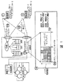
図1に示されているように、基地局13は、アップリンクにおけるキャパシティリクエスト110と、ダウンリンクにおけるキャパシティ割り当て120を交換することによって、移動局11及び12のアップリンク伝送キャパシティを制御する。キャパシティスケジューリングとは、共有アップリンクキャパシティ14を使用して、データパケットを伝送する移動局に対して、伝送速度と伝送時間を制御することである。スケジューリングタイミング140とはキャパシティスケジューリングが決定されるタイミングであり、この決定は、次のスケジューリングタイミングまで有効である。移動局は、スケジューリングインターバル内に、許可された伝送速度で送信を行う。
従って、本発明の第1の目的は、全体のアップリンクノイズライズを制限することによって、システムのキャパシティを最大限利用できるキャパシティスケジューリングを提供することである。
また、アップリンクパケットスケジューリングでは、トラフィッククラスに基づいてパケット伝送を区別することはきわめて重要である。例えば、図1における補償ビットレートトラフィッククラス11を有するストリームサービスを使用し、最小補償キャパシティを必要としている移動局1と、図1の利用可能ビットレートトラフィッククラス12を有するベストエフォート型サービスを使用しておりQoSの要求がない移動局2について考える。
これら二つのQoSトラフィッククラスがセル内にあるとき、キャパシティスケジューラー13は、システムのスループットを最大限利用する一方で、個々のトラフィッククラスのQoSを満足するような方法で、アップリンクキャパシティを効果的に利用するべきである。
すなわち、本発明の第2の目的は、複数QoSパケット伝送をサポートとするキャパシティスケジューリングを提供することである。
また、アップリンクパケットスケジューリングにおいては、優先度クラスに基づいて、パケット伝送を区別する手段が設けられていることもきわめて重要である。例えば、特別に会費を払った図1のビジネスユーザー11が、より経済性を重視したホームユーザー12よりも高い優先順位で扱われるべきであると仮定する。このように、複数の優先度がネットワーク内に共存する時、キャパシティは低い優先度のパケット伝送よりも先に、高い優先度のパケット伝送に割り当てられるように、キャパシティは有効活用されるべきである。
従って、本発明の第3の目的は、複数の優先度を有するパケット伝送をサポートするキャパシティスケジューリングを提供することである。
さらに、アップリンクパケットスケジューリングにおいて、複数のデータパケット伝送を多重化するための手段を有することも必要である。例えば、図1における移動局1‘11’のユーザーが、ストリームサービスを使用して同僚と通信している一方で、インターネットからファイルをダウンロードするかもしれない。この場合、それぞれのデータパケット伝送は、異なるトラフィッククラスと優先度を有しているので、複数QoS及び複数優先度を有するデータパケット伝送がネットワーク内に共存していることになる。図1のキャパシティスケジューリング‘13’で優先度に基づいて伝送を差別化するのと同時に、それぞれのデータパケット伝送における個々のQoSを満足するように、キャパシティは割り当てられるべきである。
従って、本発明の第4の目的は、複数QoS及び複数優先度を有するパケット伝送をサポートするキャパシティスケジューリングを提供することである。
また、アップリンクパケットスケジューリングにおいて、もしキャパシティスケジューリングが、無線チャネル環境の変化に追従できるほど早ければ、無線リソースを有効活用することができる。これは、無線チャネルのより近くでスケジューリングを行うことにより可能となる。よりノイズライズマージンを小さくできるようにアップリンクノイズライズのすばやい変動を平坦化することによって、キャパシティの向上が達成される。基地局におけるアップリンクパケットスケジューリングは、より高いシステムスループットを維持する一方で、ネットワーク内の複数QoS及び複数優先度を考慮するべきである。
すなわち、本発明の第5の目的は、複数QoS及び複数優先度をサポートする一方、システムキャパシティを最大限利用するキャパシティスケジューリングを提供することである。In WCDMA systems, the uplink capacity of a cell is managed by a distribution scheme, and mobile stations are allowed to transmit up to the maximum capacity controlled by the radio network controller. For the management of uplink noise rise, low-speed statistical multiplexing control in which the radio network controller controls the maximum transmission rate of the mobile station is used. Therefore, the fluctuation of the noise rise is large and a large noise rise margin is required, resulting in a loss of uplink capacity. In WCDMA priority processing, a data packet having a higher priority is transmitted before a data packet having a lower priority.
As a sister technology of HSDPA, capacity scheduling based on closed loop base has been proposed in 3GPP. As a reference, please refer to “TR25.896V1.0.0, Feasibility Study for Enhanced Uplink for UTRAFDD”. Uplink capacity scheduling is discussed in the Enhanced Uplink R6 Study Item. In this method, high-speed uplink scheduling in the base station is applied, and mobile station packet transmission is controlled so as to reduce cell noise rise fluctuation by limiting mobile stations that transmit packets simultaneously. In order to manage the overall noise rise, the capacity scheduler controls the uplink transmission power, transmission rate, and timing of the mobile station.
As shown in FIG. 1, the base station 13 controls the uplink transmission capacity of the
Accordingly, a first object of the present invention is to provide capacity scheduling that can make maximum use of system capacity by limiting the overall uplink noise rise.
In uplink packet scheduling, it is very important to distinguish packet transmission based on traffic class. For example, using a stream service having a compensated bit rate traffic class 11 in FIG. 1, using a
When these two QoS traffic classes are in the cell, the capacity scheduler 13 takes advantage of the uplink capacity in such a way as to satisfy the QoS of the individual traffic classes while maximizing the system throughput. Should be used.
That is, a second object of the present invention is to provide capacity scheduling that supports multi-QoS packet transmission.
In uplink packet scheduling, it is also very important to provide a means for distinguishing packet transmissions based on priority classes. For example, suppose that the business user 11 of FIG. 1 who paid a special membership fee should be treated with a higher priority than the
Accordingly, a third object of the present invention is to provide capacity scheduling that supports packet transmission having a plurality of priorities.
Furthermore, it is necessary to have means for multiplexing a plurality of data packet transmissions in uplink packet scheduling. For example, a user of mobile station 1'11 'in FIG. 1 may download a file from the Internet while communicating with a colleague using a stream service. In this case, since each data packet transmission has a different traffic class and priority, data packet transmissions having a plurality of QoS and a plurality of priorities coexist in the network. At the same time as the capacity scheduling '13' of FIG. 1 differentiates transmissions based on priority, capacity should be allocated to satisfy the individual QoS in each data packet transmission.
Accordingly, a fourth object of the present invention is to provide capacity scheduling that supports packet transmissions having multiple QoS and multiple priorities.
Also, in uplink packet scheduling, radio resources can be effectively utilized if capacity scheduling is fast enough to follow changes in the radio channel environment. This is possible by scheduling closer to the radio channel. Increased capacity is achieved by flattening the quick fluctuations in uplink noise rise so that the noise rise margin can be further reduced. Uplink packet scheduling at the base station should take into account multiple QoS and multiple priorities in the network while maintaining higher system throughput.
That is, a fifth object of the present invention is to provide a capacity scheduling that supports a plurality of QoS and a plurality of priorities while maximally utilizing a system capacity.
本発明の第1の形態によると、本方法は、基地局と移動局との間における閉ループキャパシティスケジューリングをサポートするためのものである。該方法は、それぞれのフローを該移動局におけるフローキャパシティ制御装置(FCC)に適用するステップと、該移動局に用意され、且つそれぞれ互いに異なっている複数のQoSトラフィッククラスから、選択されたトラフィッククラスとしてトラフィッククラスを選択するステップと、異なったQoSトラフィッククラスを伝送するために、該選択されたトラフィッククラスを考慮して、移動局でそれぞれのフローに優先度を割り当てるステップを有する。
本発明の第2の形態によると、該方法は、該移動局のFCCによって、該選択されたトラフィッククラスに基づき、それぞれのフローのアップリンクキャパシティを計算するステップを有する。
本発明の第3の形態によると、該方法は、優先度と選択されたトラフィッククラスとアップリンク送信電力を使用して、キャパシティリクエスト制御装置(CRC)によってそれぞれのフローのキャパシティリクエストを変更するステップと、それぞれのフローの変更キャパシティリクエストを、移動局から基地局へ伝送するステップを有する。
本発明の第4の形態によると、該方法は、該基地局で変更キャパシティリクエストを受信するステップと、該変更キャパシティリクエストを使用して、基地局でキャパシティスケジューラー(CS)によってそれぞれのフローに対する許容(allowable)キャパシティを計算するステップと、それぞれのフローの許容キャパシティを表しているキャパシティ割り当てを、基地局から移動局へ伝送するステップを有する。
本発明の第5の形態によると、該方法は、該移動局におけるキャパシティ割り当て制御装置(CAC)によって、キャパシティ割り当てを受信するステップと、該選択されたトラフィッククラスとアップリンク送信電力を使用して、CACにおいて受信されたキャパシティ割り当てを変更して、変更割り当てキャパシティとするステップと、該変更割り当てキャパシティを使用して、FCCにおける許容キャパシティをアップデートするステップを有する。
本発明の第6の形態によると、本システムは、移動局と基地局間における閉ループキャパシティスケジューリングをサポートするためのものである。該移動局は、複数のQoSトラフィッククラスからQoSトラフィッククラスを選択可能であり、選択されたQoSトラフィッククラスによって特定される、各データフローの要求アップリンクキャパシティを計算するためのフローキャパシティ制御装置(FCC)と、変更されたキャパシティを表している変更キャパシティリクエストを生ずるように、要求アップリンクキャパシティを変更するためのキャパシティリクエスト制御装置(CRC)と、該変更キャパシティリクエストを、該移動局から該基地局へ伝送する手段を有する。
本発明の第7の形態によると、該移動局は、アップリンク送信電力に基づき、受信した割り当てキャパシティを変更するキャパシティ割り当て制御装置(CAC)と、該変更割り当てキャパシティを使用して、許可(allowed)キャパシティをアップデートするFCCを有する。
本発明の第8の形態によると、該基地局は、変更キャパシティリクエストを受信するための受信手段と、移動局から送信された、選択されたトラフィッククラスと、優先度、および変更キャパシティリクエストを使用して、各フローに対する許容キャパシティを計算するためのキャパシティスケジューラーとを有している。
本発明の第9の形態によると、本方法は、複数のアップリンクデータフローに対するアップリンクキャパシティを基地局で管理するためのものである。該方法は、最大アップリンクキャパシティとスケジューリングできないアップリンクキャパシティとの差異を表す、スケジュール可能なアップリンクキャパシティを基地局において計算するステップと、移動局から送信されたキャパシティリクエストを受信するステップと、最小QoS要求を満たすために、各フローへ割り当てられた優先度に基づいて、各フローに対する最小QoSキャパシティを計算するステップと、各フローへ最小QoSを割り当てるステップとを有する。
本発明の第10の形態によると、該方法は、最小QoSキャパシティを割り当てたあとに残った利用可能且つスケジュール可能なアップリンクキャパシティを最大限利用できるように、各フローに対する追加リクエストキャパシティを計算するステップと、追加リクエストキャパシティを有する各フローに、残りのキャパシティを割り当てるステップとを有する。
本発明の特定の形態によると、本方法は、基地局と複数の移動局との間における閉ループキャパシティスケジューリングをサポートするものである。該方法は、
1.各フローのトラフィッククラスによって、それぞれのフローをフローキャパシティ制御装置(FCC)に入力し、優先度とキャパシティの初期値を各フローに割り当てるステップと、
2.移動局において、データフローに属するデータパケットを、割り当てられたデータパケット待ち行列(キュー)に保存するステップと、
3.移動局におけるフローキャパシティ制御装置において、要求サービス品質に基づき、データフローの要求アップリンクキャパシティを計算するステップと、
4.キャパシティリクエスト制御装置(CRC)において、割り当てられた優先度を用いて前記データフローセットのキャパシティリクエストを変更し、該移動局から該基地局に変更キャパシティリクエストを送信するステップと、
5.前記複数の移動局から送られたキャパシティリクエストを基地局で受信し、前記複数の移動局から送られたデータパケットを受信した後、再送データパケットを計算するステップと、
6.基地局におけるキャパシティスケジューラーが、割り当てられたQoSトラフィッククラスと優先度と、受信したキャパシティリクエストを使用して、各フローに対する許容キャパシティを計算するステップと、
7.基地局がキャパシティ割り当てを送信し、キャパシティ割り当て制御装置において、割り当てられた優先度を使用して、データフローのセットを受信された割り当てキャパシティを変更するステップと、
8.フローキャパシティ制御装置において、セット内のデータフローの変更割り当てキャパシティを使用して、許可キャパシティをアップデートするステップとを有する。
本発明の他の形態によると、サブシステムは、複数のアップリンクデータフローに対して、基地局でアップリンクキャパシティをスケジューリングするためにアップリンクキャパシティを管理するシステムに用いられる。該システムは、
1.基地局においてスケジュール可能なアップリンクキャパシティを評価し、そのスケジュール可能なアップリンクキャパシティは、最大アップリンクキャパシティと非スケジューラブルアップリンクキャパシティの差異であるようなステップと、
2.上記の方法でキャパシティリクエストを受信し、処理するステップと、
3.前のデータパケット伝送の受信状態(から、要求される再送パケット用のキャパシティを計算し、割り当てるステップと、
4.最小QoS要求を満たすために、前記セットにおけるフローに対する最小QoSキャパシティ(特に、GBR、ABR、TBRに対しては、補償キャパシティ、最小容量及び要求キャパシティがそれぞれ最小QoSキャパシティである)をそれぞれを計算するステップと、
5.割り当てられた優先度に基づいて、前記セットにおけるフローに最小QoSキャパシティを割り当てるステップと、
6.再送及び最小QoSキャパシティを割り当てた後に残った、利用可能且つスケジュール可能なアップリンクキャパシティを最大限有効活用するように前記フローセットにおける追加リクエストキャパシティ(GBR及びABRに対しては、各々補償キャパシティと最小容量以上のキャパシティが追加リクエストキャパシティである)を計算するステップと、
7.割り当てられた優先度に基づいて、前記セットにおける追加リクエストキャパシティを有するフロー(特に、優先度が低いフローよりも前に、より高い優先度のフローにキャパシティが割り当てられる。残りのキャパシティが優先度に比例して割り当てられるのが好ましい。)に残りのキャパシティを割り当てるステップと、
8.再送、最小QoS及び残りのキャパシティを使用して、各フローに対する全キャパシティを計算し、移動局へ伝送するステップを有する。
本発明の他の形態によると、方法は、移動局においてアップリンクキャパシティフローキャパシティ制御装置を管理するために用いられる。該方法は、
1.トラフィッククラスを使用して、前記セットの各フローのQoSパラメータを割り当てるステップと、(ただし、QoSトラフィッククラスは、補償ビットレート、ターゲットビットレート、及び利用可能ビットレートを含むことが好ましい。また、要求QoSパラメータは、最大容量、最小容量、ターゲットキャパシティ及び補償キャパシティを含むことが好ましい)
2.前記セット内の各フローの再送キャパシティを計算するステップと、
3.QoS要求を満足するように、新しいデータパケット伝送に対する要求キャパシティを計算するステップと、
4.アップリンクキャパシティスケジューラに対するキャパシティリクエストを計算するステップを有する。
本発明の他の形態によると、本方法は、キャパシティリクエストと割り当てメッセージをシグナリングすることに用いられ、
1.前記フローセットにおけるフローのキャパシティリクエストとフローIDを含むキャパシティリクエストメッセージを生成するステップと(ただし、キャパシティリクエストメッセージは移動局で符号化され、基地局で復号化されることが好ましい)、
2.移動局からキャパシティリクエストメッセージを伝送して、基地局で受信するステップと(キャパシティリクエストメッセージは、個別アップリンクチャネルを介して伝送されることが好ましい)、
3.セット内のフローのキャパシティ割り当てとフローIDを含むキャパシティ割り当てメッセージを生成するステップと(キャパシティ割り当てメッセージは基地局で符号化され、移動局で復号化されることが好ましい)、
4.基地局からキャパシティ割り当てメッセージを伝送し、前記移動局で受信するステップ(ただし、キャパシティ割り当てメッセージは、個別のダウンリンク制御チャネルを介して伝送されることが好ましい)とを有する。
本発明の第1の利点は、基地局におけるQoS及び優先度を考慮したアップリンクキャパシティスケジューリングを可能にすることである。アップリンクデータフローのキャパシティが、移動局の最大容量を制御することによりラフに制御されているようなシステムと比較して、本発明では、データフローの優先度及びQoSの両方が基地局によって処理可能であり、基地局はフローのQoSと優先度の両方を考慮することができる。
さらに、本発明の第2の利点は、移動局及び基地局の両方が、優先度に加えてデータフローのQoSをも認識することである。WCDMAにおける現在の速度割り当て方法では、複数のアップリンクデータフロー間でアップリンクキャパシティを分配するときに、データフローの優先度のみが考慮されている。本願では、要求フローキャパシティを最小QoSと残りのキャパシティに分割することが可能なので、より優先度の低いデータフローの最小QoSキャパシティが、より優先度の高いデータフローの追加QoSキャパシティより先に補償される。
本発明の第3の利点は、移動局が、データフローのQoS及び優先度を考慮して、キャパシティリクエストとキャパシティ割り当てを調整することができる点である。キャパシティリクエストの調整は、要求キャパシティの合計が、所定のアップリンク伝送電力において不足している時に、きわめて重要である。また、キャパシティ割り当ての調整は、スケジューリング遅延が発生している際に要求される。本願では、QoS及び優先度を考慮した調整が提案されており、より低い優先度を有するフローの追加キャパシティでも、より高い優先度を有する最小QoSキャパシティより先に調整される。According to a first aspect of the invention, the method is for supporting closed loop capacity scheduling between a base station and a mobile station. The method includes the steps of applying each flow to a flow capacity controller (FCC) in the mobile station, and selected traffic from a plurality of QoS traffic classes prepared in the mobile station and different from each other. Selecting a traffic class as a class and assigning a priority to each flow at the mobile station in consideration of the selected traffic class in order to transmit different QoS traffic classes.
According to a second aspect of the invention, the method comprises the step of calculating the uplink capacity of each flow based on the selected traffic class by the FCC of the mobile station.
According to a third aspect of the invention, the method modifies the capacity request for each flow by a capacity request controller (CRC) using the priority, the selected traffic class and the uplink transmission power. And transmitting a change capacity request for each flow from the mobile station to the base station.
According to a fourth aspect of the present invention, the method comprises the steps of receiving a modified capacity request at the base station, and using the modified capacity request at each base station by a capacity scheduler (CS). Calculating an allowable capacity for the flow and transmitting a capacity allocation representing the allowable capacity of each flow from the base station to the mobile station.
According to a fifth aspect of the invention, the method uses a capacity allocation controller (CAC) in the mobile station to receive a capacity allocation, and uses the selected traffic class and uplink transmission power. And changing the capacity allocation received in the CAC to change allocation capacity, and using the change allocation capacity to update the allowable capacity in the FCC.
According to a sixth aspect of the present invention, the system is for supporting closed loop capacity scheduling between a mobile station and a base station. The mobile station is capable of selecting a QoS traffic class from a plurality of QoS traffic classes, and a flow capacity controller for calculating a required uplink capacity of each data flow specified by the selected QoS traffic class (FCC), a capacity request controller (CRC) for changing the requested uplink capacity to produce a changed capacity request representing the changed capacity, and the changed capacity request, Means for transmitting from the mobile station to the base station;
According to a seventh aspect of the present invention, the mobile station uses a capacity allocation controller (CAC) that changes a received allocation capacity based on uplink transmission power, and the change allocation capacity, It has an FCC that updates the allowed capacity.
According to an eighth aspect of the present invention, the base station comprises a receiving means for receiving a modified capacity request, a selected traffic class, a priority, and a modified capacity request transmitted from the mobile station. And a capacity scheduler for calculating the allowable capacity for each flow.
According to a ninth aspect of the invention, the method is for managing uplink capacity for a plurality of uplink data flows at a base station. The method calculates at a base station a schedulable uplink capacity representing a difference between maximum uplink capacity and non-schedulable uplink capacity, and receives a capacity request transmitted from a mobile station. Calculating a minimum QoS capacity for each flow based on the priority assigned to each flow to satisfy the minimum QoS requirement, and assigning a minimum QoS to each flow.
According to a tenth aspect of the present invention, the method includes additional request capacity for each flow so that the available and schedulable uplink capacity remaining after allocating the minimum QoS capacity can be maximized. And assigning the remaining capacity to each flow having additional request capacity.
According to a particular form of the invention, the method supports closed-loop capacity scheduling between a base station and a plurality of mobile stations. The method
1. Depending on the traffic class of each flow, entering each flow into a flow capacity controller (FCC) and assigning priority and capacity initial values to each flow;
2. Storing, in a mobile station, data packets belonging to a data flow in an assigned data packet queue (queue);
3. In the flow capacity control apparatus in the mobile station, calculating the required uplink capacity of the data flow based on the required service quality;
4). In a capacity request controller (CRC), changing the capacity request of the data flow set using the assigned priority, and transmitting the changed capacity request from the mobile station to the base station;
5). Receiving a capacity request sent from the plurality of mobile stations at a base station, receiving a data packet sent from the plurality of mobile stations, and calculating a retransmission data packet;
6). A capacity scheduler at the base station using the assigned QoS traffic class and priority and the received capacity request to calculate an allowable capacity for each flow;
7). A base station transmits a capacity allocation and, at a capacity allocation controller, uses the allocated priority to change the allocated capacity received set of data flows;
8). In the flow capacity controller, updating the allowed capacity using the change allocation capacity of the data flows in the set.
According to another aspect of the present invention, the subsystem is used in a system for managing uplink capacity in order to schedule uplink capacity at a base station for a plurality of uplink data flows. The system
1. Assessing schedulable uplink capacity at the base station, the schedulable uplink capacity being the difference between the maximum uplink capacity and the non-schedulable uplink capacity;
2. Receiving and processing a capacity request in the manner described above;
3. Calculating and assigning the capacity for the requested retransmission packet from the reception state of the previous data packet transmission (
4). To meet the minimum QoS requirements, the minimum QoS capacity for the flows in the set (especially for GBR, ABR, TBR, the compensation capacity, the minimum capacity, and the requested capacity are the minimum QoS capacity) Calculating each one, and
5). Assigning a minimum QoS capacity to the flows in the set based on the assigned priority;
6). Additional request capacity in the flow set (for GBR and ABR, respectively compensated to make the best use of the available and schedulable uplink capacity remaining after assigning retransmission and minimum QoS capacity. Calculating capacity and capacity above minimum capacity is additional request capacity);
7). Based on the assigned priority, flows with additional request capacity in the set (especially, higher priority flows are assigned capacity before lower priority flows. The remaining capacity is Allocating the remaining capacity to the preferred capacity),
8). Using the retransmission, the minimum QoS and the remaining capacity, the total capacity for each flow is calculated and transmitted to the mobile station.
According to another aspect of the invention, the method is used for managing an uplink capacity flow capacity controller in a mobile station. The method
1. Assigning QoS parameters for each flow in the set using a traffic class (where the QoS traffic class preferably includes a compensation bit rate, a target bit rate, and an available bit rate. The QoS parameters preferably include maximum capacity, minimum capacity, target capacity and compensation capacity)
2. Calculating the retransmission capacity of each flow in the set;
3. Calculating a request capacity for a new data packet transmission to satisfy a QoS requirement;
4). Calculating a capacity request for the uplink capacity scheduler.
According to another aspect of the invention, the method is used for signaling capacity requests and assignment messages;
1. Generating a capacity request message including a flow capacity request and a flow ID in the flow set (however, the capacity request message is preferably encoded by the mobile station and decoded by the base station);
2. Transmitting a capacity request message from the mobile station and receiving it at the base station (the capacity request message is preferably transmitted via a dedicated uplink channel);
3. Generating a capacity allocation message including the capacity allocation and flow ID of the flows in the set (the capacity allocation message is preferably encoded at the base station and decoded at the mobile station);
4). Transmitting a capacity allocation message from a base station and receiving it at the mobile station (however, the capacity allocation message is preferably transmitted via a separate downlink control channel).
A first advantage of the present invention is that it enables uplink capacity scheduling considering QoS and priority at the base station. Compared to a system where the capacity of the uplink data flow is roughly controlled by controlling the maximum capacity of the mobile station, in the present invention, both the priority and QoS of the data flow are determined by the base station. The base station can consider both the QoS and priority of the flow.
Furthermore, a second advantage of the present invention is that both the mobile station and the base station recognize the QoS of the data flow in addition to the priority. In current rate allocation methods in WCDMA, only the priority of data flows is taken into account when distributing uplink capacity among multiple uplink data flows. In the present application, it is possible to divide the requested flow capacity into minimum QoS and remaining capacity, so the minimum QoS capacity of the lower priority data flow is higher than the additional QoS capacity of the higher priority data flow. First compensated.
A third advantage of the present invention is that the mobile station can adjust capacity requests and capacity allocation taking into account the QoS and priority of the data flow. Capacity request adjustment is critical when the total requested capacity is insufficient for a given uplink transmission power. Also, capacity allocation adjustment is required when scheduling delays occur. In the present application, an adjustment considering QoS and priority is proposed, and even an additional capacity of a flow having a lower priority is adjusted before a minimum QoS capacity having a higher priority.
図1は基地局が移動局に対して行うアップリンクキャパシティ制御について説明するための図である。
図2は複数QoSトラフィッククラスと優先度処理をサポートするためのキャパシティスケジューリングの一般的概略図である。
図3は一般的なフローキャパシティ制御装置を説明しているフローチャートである。
図4はGBRトラフィッククラスのためのフローキャパシティ制御装置のフローチャートである。
図5はTBRトラフィッククラスのためのフローキャパシティ制御装置のフローチャートである。
図6はキャパシティスケジューラーの一般的フローチャートを示した図であり、複数QoS及び複数優先度フローをサポートするための階層的キャパシティ割り当てについて説明するための図である。
図7は第2の実施形態に用いられるアップリンク及びダウンリンクチャネルを含む、複数の移動局と一つの基地局を有するシステム構成を示した図である。FIG. 1 is a diagram for explaining uplink capacity control performed by a base station for a mobile station.
FIG. 2 is a general schematic diagram of capacity scheduling to support multiple QoS traffic classes and priority processing.
FIG. 3 is a flowchart illustrating a general flow capacity control apparatus.
FIG. 4 is a flow chart of the flow capacity controller for the GBR traffic class.
FIG. 5 is a flowchart of the flow capacity controller for the TBR traffic class.
FIG. 6 is a diagram illustrating a general flow chart of the capacity scheduler, and is a diagram for explaining hierarchical capacity allocation for supporting a plurality of QoS and a plurality of priority flows.
FIG. 7 is a diagram showing a system configuration including a plurality of mobile stations and one base station including uplink and downlink channels used in the second embodiment.
本発明は、セル内で閉ループアップリンクキャパシティスケジューリングを維持するためのものである。図2は、アップリンク及びダウンリンクチャネルを含む、複数の移動局と一つの基地局を有するシステム構成を示している。移動局には、フローキャパシティ制御装置(FCC)、キャパシティリクエスト制御装置(CRC)フローキュー、TFC制御装置(TFCC)、フロー多重化器(FMUX)、及び符号化器(ENC)が存在する。基地局には、キャパシティスケジューラー(CS)と、復号化器(DEC)、フロー分離器(FDEMUX)、フローキューが存在する。
移動局において、アップリンクで送信されるデータパケットが、図2のアップリンクデータフローキュー211で保存される。フローキューには常にフローキャパシティ制御装置(FCC)212が付属しており、このFCCはQoSパラメータ、独自のID番号、フローキューの待ち行列サイズに関する情報を保持している。
新しいデータフローを確立する際に、無線ネットワーク制御装置は初期キャパシティを設定することが好ましく、初期キャパシティはFCCに信号で伝えられる。FCCは、フローの要求QoSに基づいて、データフローの要求アップリンクキャパシティを計算し、キャパシティリクエスト(CR)を生成し、CRはその後キャパシティリクエスト制御装置(CRC)213に送られる。CRCは図2における、現在利用可能な送信電力の残存量2130を調べて、収容可能な全アップリンクキャパシティを計算する。
CRCに接続されているFCCからのキャパシティリクエストの全体の量が収容可能なアップリンクキャパシティよりも大きい場合には、CRCは、最も優先度の低いフローから最も優先度の高いフローの順にCRの量を削減する。CRCがCRを多重化した後、基地局にあるアップリンクキャパシティスケジューラーにCRMが伝送される「221」。それからスケジューラーの決定は、各データフローに対する許可アップリンクキャパシティを示すキャパシティ割り当てメッセージ(CAM)として移動局に送信される。CAMはキャパシティ割り当て制御装置(CAC)「214」によって受信され、分離されて各FCCに入る。CACは、利用可能な送信電力の残存量に基づき、サポート可能なアップリンクキャパシティを計算する。もし受信されたCAMの全体の量が収納可能なアップリンクキャパシティの量よりも多い場合には、CACは、最も優先度の低いフローから最も優先度の高いフローの順にCAMを削減する。
この方法において、各FCCは独立に、キャパシティスケジューラーによって処理されるCAMとCRMの閉ループ制御を実行する。
移動局において、アップリンクデータ伝送は、以下の方法で実行される:TFC制御装置(TFCC)215は、各データフローに割り当てられたフローキャパシティを集め、各フローが割り当てられたフローキャパシティまでデータパケットを送信するという方法を用いて、トランスポートフォーマットの組合せを計算する。TFCC215はまた、基地局にTFCI(Transport Format Combination Indicator)を送る。TFCIが選択されたら、フローキューからのデータパケットはENC216によって符号化され、FMUX217によって多重化される。TFCIは、多重化データパケットに加えて、アップリンクトラフィックチャネルに送られる。
基地局において、以下の方法でアップリンクデータ受信が実行される:
フロー分解器(FDEMUX)221は受信したビットストリームを分離サブビットストリームに分離し、分離サブビットストリームはDEC222によって別々に復号化される。復号化に成功したデータパケットは、それぞれのフローキューに保存される「223」。DEC222は、各データパケットの復号化状態を再送制御装置(RETXC)に報告し、RETXCはアップリンクキャパシティスケジューラー225にその状態を送信する。
基地局において、移動局からのCRMは受信され「226」、キャパシティスケジューラー(CS)225に与えられる。CS225によってCAMが生成され、移動局に伝送される「227」。
アップリンク制御チャネルにおいて、CRMは移動局から基地局に伝送される「241」。各CRMは各フローの要求キャパシティとFIDを含んでいる。CRMは、移動局で符号化され、基地局で復号化されることが好ましい。移動局は、現在の送信電力の残存量についての報告を送信することが望ましい。また、各移動局は別々のUL制御チャネルを伝送することが好ましい。
ダウンリンクエアインターフェースにおいて、CAMは、基地局から移動局へ伝送される「242」。各CAMは、各フローに対する許可キャパシティとFIDを含んでいる。CAMは、基地局で符号化され、移動局で復号化されることが好ましい。基地局は、CAMを受信する移動局に対し、共有ダウンリンク制御チャネルによって送信することが好ましい。
フローキャパシティ制御装置の一般的構造は図3に示されている。制御装置の詳細な実装についてはフローのトラフィッククラスに依存するが、この図では、すべてのトラフィッククラスに共通している、主な手順が示されている。FCCは、少なくとも図3のスケジューリングインターバル31と同じ時間で実行される。FCCの入力パラメータは、フローに対する現在の割り当てキャパシティ(AC)、再送用要求キャパシティ(RCR)、及びフローのQoSパラメータである。各トラフィッククラスは各々QoSパラメータセットを有することが好ましい。FCCの出力パラメータは、再送用割り当てキャパシティ(ACRT)、新送信用割り当てキャパシティ(ACNT)、及びキャパシティリクエスト(CR)である。まず初めに、FCCは、図3のパケットデータの要求遅延32、33を満足するために、再送用要求キャパシティを計算する。要求遅延は、FCCができるだけ必要とするキャパシティを再送に割り当てられるように、厳しく設定することが好ましい。次に、FCCは、図3に340、341、35で示されている、フローの最小QoSキャパシティと追加QoSキャパシティの両方を含んでいる、新しいデータ送信用の要求リクエストを計算する。図3の残存キャパシティ(LOL)360は、ACとACRT及びACNTの合計の差異に相当する。最後に、CRは、次のスケジューリングインターバルに対して、さらにキャパシティが必要かどうかを計算する。
GBRとは、キャパシティがスケジューラーによって所定のレベルまで補償されたトラフィッククラスのことである。GBRトラフィッククラスのQoSパラメータは、最大容量(MC)と補償キャパシティ(GC)である。GCが最小補償キャパシティであるのに対し、MCは許容キャパシティの上限である。スケジューラーは、アップリンクキャパシティの使用可能率に基づいて、GCよりも多くのキャパシティを割り当てる。
GBRトラフィッククラスに関するFCCの実行については、図4に示されている。GBRトラフィッククラスのQoSパラメータは、最大容量(MC)と補償キャパシティ(GC)である。再送データは、新しい送信データより高い優先度を有している。従って、まず初めにACが再送データに割り当てられ、次に、残存キャパシティがデータ(41、42)に割り当てられる。新しい送信への割り当てに関しては、下限値が現在のフローキューサイズ(QC)か新送信用に利用可能なキャパシティ(NDC)のいずれかであるのに対して、上限値は、QoSパラメータである最大容量が使用される。従って、NDCがMCより大きいか、QCがNDCより小さい場合においてのみ、LOCが正となることは明らかである。最後に、キャパシティリクエスト(CR)が、最大容量(MC)と残存フローキューサイズ(QC−ACNT)を比較することによって、計算される(図4における43)。
ABRは、キャパシティの使用可能な割合に基づいて割り当てられるキャパシティが決定されるトラフィッククラスのことである。ABRトラフィッククラスのQoSパラメータは、最大容量(MC)と最小容量(MNC)である。MNCは、TCPやTCKのような小さなデータパケットを任意タイミングで送信するための最小容量であり、一方、MCは許容キャパシティの上限である。
ABR FCCの実装方法はGBR FCCの場合に、補償キャパシティ(GC)のQoSパラメータをゼロに設定した場合と同じである。この場合、キャパシティスケジューラーに対するQoS要求が無いため、可能な限りたくさんのキャパシティを割り当てることができる。CSは、小さなデータパケットを任意のタイミングで送信するために、少なくともMNCを割り当てることが好ましい。
TBRは、キャパシティがターゲットレベルで管理されているトラフィッククラスである。TBRトラフィッククラスのQoSパラメータは、最大容量(MC)とターゲットキャパシティ(TC)である。FCCは、平均キャパシティがターゲットキャパシティとなるよう瞬時キャパシティを制御する一方、MCを許容キャパシティの上限値とする。
図5には、TBR FCCの実装例が示されている。再送データは、新しい送信データより高い優先度を有している。従って、まず初めに再送データにACが割り当てられ、次に、残りのキャパシティが新しい送信データ(図5の51)に割り当てられる。新しい送信への割り当てに関して、初めに、割り当てられたキャパシティの現在の移動平均(MAAC)とTC(52)の差が計算される。それからTCを満足するような要求キャパシティを(53、530)計算する。そして、割り当てキャパシティ(ACNT)がMCとキューサイズ(QC)を超過しないように54、キャパシティ割り当てが実行される。新たに計算されたACNT(55)を使用して移動平均をとることによってMAACをアップデートし、最終的にTCを満足するようにキャパシティリクエスト(CR)が計算される(56)。収束速度を上げるために、指数関数的な調整制御を使用してもよい(530)。
アップリンクキャパシティスケジューラーの実装例が図6に示されている。スケジューリングインターバルの初めに、図6に示すように基地局は、熱雑音、セル間干渉、及び非スケジューラブルデータ伝送601を含む、非スケジューラブルアップリンクキャパシティを測定する。非スケジューラブルデータ伝送は、スケジューラーが制御していない、バックグラウンドロードである。CSは、最大容量及び非スケジューラブルキャパシティとの差である、利用可能且つスケジュール可能なキャパシティを計算する。
移動局からのキャパシティリクエストの受信に際し、基地局はキャパシティリクエストの調整を実行するが、その様子は、図6の602の通りである:
基地局は、各移動局に対する許可送信電力ヘッドルームの最小値を割り当てた後、各移動局に対するサポート可能な最大キャパシティを計算する。許可送信電力ヘッドルームの最小値は、ネットワーク内における他セルへの干渉を制御する。一定の許可送信電力ヘッドルームの最小値でサポート可能な最大キャパシティは、要求されるキャパシティの合計値と比較される。サポート可能な最大キャパシティが、要求キャパシティの合計値よりも大きくなるように、最も優先度の低いフローから最も優先度の高いフローの順にキャパシティリクエストの追加QoSキャパシティ部分が削減される。もしそれでも十分でなければ、キャパシティリクエストの最小QoSキャパシティ部分が、最も優先度の低いフローから最も優先度の高いフローの順に削減される。それでも十分でなければ、要求キャパシティの再送部分が、最も優先度の低いフローから最も優先度の高いフローの順に削減される。基地局は、要求再送キャパシティ(RCRTX)、各優先度レベル(RCMQ(1)からRCMQ(N))に対する最小QoSキャパシティ、そして全ての移動局に対する追加QoSキャパシティ(RCEQ(1)からRCEQ(N))の全量を計算する。基地局はまた、各移動局のフロー毎に、フロー情報及び報告を受けたキャパシティリクエストを用いて、再送キャパシティ、最小QoSキャパシティ及び追加QoSキャパシティを計算する。
全スケジュール可能なキャパシティより小さくなるべきである、割り当てキャパシティの合計値をスケジュール可能な全キャパシティ
よりも小さくするために、基地局はまず図6にあるように、スケジュール可能なキャパシティを再送キャパシティ61に割り当てる。もし、スケジュール可能な全キャパシティが要求再送キャパシティの合計値を満たすのに十分でない場合、基地局は、最も優先度の高いフローから最も優先度の低いフローの順に再送キャパシティを割り当てる。もしも、スケジュール可能な全キャパシティが要求再送キャパシティの合計値を満たすのに十分な場合、基地局は、図6の最も優先度の高いフロー62から最も優先度の低いフロー63の順で、残りのスケジュール可能なキャパシティを最小QoSキャパシティに割り当てる。もしこれでもまだスケジュール可能なキャパシティが十分な場合、基地局は、図6の最も優先度の高いフロー64からの最も優先度の低いフロー65の順に、追加QoSキャパシティに残りのスケジュール可能なキャパシティを割り当てる。同じ優先度レベルに属するフロー間において、キャパシティは公正なスケジューリング方法において、分配されることが好ましい。最後に基地局は、各移動局の各フローに対して、割り当て再送キャパシティ、割り当て最小QoSキャパシティ及び割り当て追加QoSキャパシティの合計である全割り当てキャパシティを計算する。
以下に本発明の第2の実施形態に関して図7を参照して説明する。
図7は第2の実施形態に用いられるアップリンク及びダウンリンクチャネルを含む、複数の移動局と一つの基地局を有するシステム構成を示している。
図7が第1の実施形態におけるシステム構成を示す図2と異なる点は、図2におけるCACを具備していない点である。その代わり、第2の実施形態におけるシステム構成では、基地局が送信するCAMはTFCC「215」にて受信される。CAMは、各移動局に割り当てられた総割り当てキャパシティを示しており、TFCCは総割り当てキャパシティ以下で、且つ移動局の最大電力以下となるようなトランスポートフォーマットの組み合わせを選択する。このときTFCCは優先度の高いフローの要求品質が、優先度の低いフローの要求品質よりも先に満たされるようにトランスポートフォーマットの組み合わせを決定する。その後、TFCCは選択したトランスポートフォーマットの組み合わせを示すTFCIを基地局に送るとともに、選択したトランスポートフォーマットの組み合わせに関する情報をFCCへ送る。
FCCは、選択したトランスポートフォーマットの組み合わせの情報から各データフローに割り当てられたキャパシティの情報を取り出し、フローの要求QoSに基づいて、データフローの要求アップリンクキャパシティを計算しキャパシティリクエスト(CR)を生成する。その後は、CRはCRCに送られ、第1の実施形態と同様な手順で多重化し、キャパシティリクエストメッセージ(CRM)として基地局にあるキャパシティスケジューラー(CS)に送信される。
ここで、第2の実施形態におけるCSは、図6で説明した第1の実施形態におけるCSと同じ手順で各フローの割り当てキャパシティを計算する。その後、本実施形態におけるCSは、計算した各フローに対する割り当てキャパシティの合計(総割り当てキャパシティ)を計算し、総割り当てキャパシティを示すキャパシティ割り当てメッセージ(CAM)を下り回線において移動局に送信する。
以上に述べた点が、第2の実施形態が第1の実施形態と異なる点であり、それ以外の部分は第1の実施形態と同じであるため省略する。The present invention is for maintaining closed loop uplink capacity scheduling within a cell. FIG. 2 shows a system configuration having a plurality of mobile stations and one base station, including uplink and downlink channels. The mobile station includes a flow capacity controller (FCC), a capacity request controller (CRC) flow queue, a TFC controller (TFCC), a flow multiplexer (FMUX), and an encoder (ENC). . In the base station, there are a capacity scheduler (CS), a decoder (DEC), a flow separator (FDEMUX), and a flow queue.
In the mobile station, data packets transmitted on the uplink are stored in the uplink
In establishing a new data flow, the radio network controller preferably sets the initial capacity, which is signaled to the FCC. The FCC calculates the requested uplink capacity of the data flow based on the flow's requested QoS and generates a capacity request (CR), which is then sent to the capacity request controller (CRC) 213. The CRC examines the remaining
If the total amount of capacity requests from the FCC connected to the CRC is greater than the accommodable uplink capacity, the CRC is in the order of the lowest priority flow to the highest priority flow. Reduce the amount of After the CRC multiplexes the CR, the CRM is transmitted to the uplink capacity scheduler in the base station “221”. The scheduler decision is then sent to the mobile station as a capacity allocation message (CAM) indicating the allowed uplink capacity for each data flow. The CAM is received by a capacity allocation controller (CAC) “214”, separated and entered into each FCC. The CAC calculates the supported uplink capacity based on the remaining amount of available transmit power. If the total amount of CAM received is greater than the amount of uplink capacity that can be accommodated, the CAC reduces the CAM in order from the lowest priority flow to the highest priority flow.
In this way, each FCC independently performs a closed loop control of the CAM and CRM processed by the capacity scheduler.
At the mobile station, uplink data transmission is performed in the following manner: TFC controller (TFCC) 215 collects the flow capacity assigned to each data flow and up to the flow capacity to which each flow is assigned. A transport format combination is calculated using a method of transmitting data packets. The
At the base station, uplink data reception is performed in the following manner:
A flow decomposer (FDEUX) 221 separates the received bitstream into separated sub-bitstreams, which are separately decoded by the
At the base station, the CRM from the mobile station is received “226” and provided to the capacity scheduler (CS) 225. A CAM is generated by the
In the uplink control channel, CRM is transmitted “241” from the mobile station to the base station. Each CRM contains the requested capacity and FID for each flow. The CRM is preferably encoded at the mobile station and decoded at the base station. It is desirable for the mobile station to transmit a report on the current remaining amount of transmission power. Each mobile station preferably transmits a separate UL control channel.
In the downlink air interface, the CAM is transmitted “242” from the base station to the mobile station. Each CAM includes an allowed capacity and FID for each flow. The CAM is preferably encoded at the base station and decoded at the mobile station. The base station preferably transmits to the mobile station that receives the CAM via a shared downlink control channel.
The general structure of the flow capacity controller is shown in FIG. The detailed implementation of the controller depends on the traffic class of the flow, but this figure shows the main steps that are common to all traffic classes. The FCC is executed at least at the same time as the
GBR is a traffic class whose capacity is compensated to a predetermined level by a scheduler. The QoS parameters of the GBR traffic class are maximum capacity (MC) and compensation capacity (GC). While GC is the minimum compensation capacity, MC is the upper limit of allowable capacity. The scheduler allocates more capacity than GC based on uplink capacity availability.
The FCC implementation for the GBR traffic class is illustrated in FIG. The QoS parameters of the GBR traffic class are maximum capacity (MC) and compensation capacity (GC). The retransmission data has a higher priority than the new transmission data. Therefore, AC is first assigned to retransmission data, and then remaining capacity is assigned to data (41, 42). For allocation to new transmissions, the lower limit is either the current flow queue size (QC) or the capacity available for new transmissions (NDC), whereas the upper limit is a QoS parameter. Maximum capacity is used. Thus, it is clear that LOC is positive only when NDC is greater than MC or QC is less than NDC. Finally, the capacity request (CR) is calculated by comparing the maximum capacity (MC) and the remaining flow queue size (QC-ACNT) (43 in FIG. 4).
ABR is a traffic class in which allocated capacity is determined based on the available percentage of capacity. The QoS parameters of the ABR traffic class are maximum capacity (MC) and minimum capacity (MNC). MNC is the minimum capacity for transmitting small data packets such as TCP and TCK at an arbitrary timing, while MC is the upper limit of allowable capacity.
The implementation method of the ABR FCC is the same as that when the QoS parameter of the compensation capacity (GC) is set to zero in the case of the GBR FCC. In this case, since there is no QoS requirement for the capacity scheduler, as much capacity as possible can be allocated. The CS preferably allocates at least an MNC in order to transmit a small data packet at an arbitrary timing.
The TBR is a traffic class whose capacity is managed at a target level. The QoS parameters of the TBR traffic class are maximum capacity (MC) and target capacity (TC). The FCC controls the instantaneous capacity so that the average capacity becomes the target capacity, while setting MC as the upper limit value of the allowable capacity.
FIG. 5 shows an implementation example of TBR FCC. The retransmission data has a higher priority than the new transmission data. Therefore, AC is first assigned to retransmission data, and then the remaining capacity is assigned to new transmission data (51 in FIG. 5). For assignment to a new transmission, first the difference between the current moving average (MAAC) and TC (52) of the assigned capacity is calculated. Then, the required capacity that satisfies TC is calculated (53, 530). Then, capacity allocation is executed 54 so that the allocation capacity (ACNT) does not exceed the MC and queue size (QC). The MAAC is updated by taking a moving average using the newly calculated ACNT (55), and finally a capacity request (CR) is calculated to satisfy TC (56). Exponential adjustment control may be used to increase convergence speed (530).
An example implementation of an uplink capacity scheduler is shown in FIG. At the beginning of the scheduling interval, the base station measures non-schedulable uplink capacity, including thermal noise, inter-cell interference, and
Upon receiving the capacity request from the mobile station, the base station performs capacity request adjustment as shown in FIG. 6 at 602:
The base station assigns a minimum allowed transmission power headroom for each mobile station and then calculates the maximum capacity that can be supported for each mobile station. The minimum allowed transmission power headroom controls interference to other cells in the network. The maximum capacity that can be supported by the minimum value of a certain allowed transmit power headroom is compared to the total required capacity. The additional QoS capacity portion of the capacity request is reduced in order from the lowest priority flow to the highest priority flow so that the maximum capacity that can be supported is greater than the total requested capacity. If still not enough, the minimum QoS capacity portion of the capacity request is reduced from the lowest priority flow to the highest priority flow. If that is not enough, the retransmission portion of the requested capacity is reduced from the flow with the lowest priority to the flow with the highest priority. The base station may request requested capacity (RCRTX), minimum QoS capacity for each priority level (RCCM (1) to RCMM (N)), and additional QoS capacity for all mobile stations (RCEQ (1) to RCEQ). (N)) is calculated. The base station also calculates retransmission capacity, minimum QoS capacity and additional QoS capacity for each mobile station flow using the flow information and the capacity request received.
To make the total allocated capacity smaller than the total schedulable capacity, which should be less than the total schedulable capacity, the base station first sets the schedulable capacity as shown in FIG. Assigned to
Hereinafter, a second embodiment of the present invention will be described with reference to FIG.
FIG. 7 shows a system configuration including a plurality of mobile stations and one base station including uplink and downlink channels used in the second embodiment.
FIG. 7 differs from FIG. 2 showing the system configuration in the first embodiment in that the CAC in FIG. 2 is not provided. Instead, in the system configuration in the second embodiment, the CAM transmitted by the base station is received by TFCC “215”. The CAM indicates the total allocated capacity allocated to each mobile station, and the TFCC selects a transport format combination that is less than the total allocated capacity and less than the maximum power of the mobile station. At this time, the TFCC determines a combination of transport formats so that the required quality of the high priority flow is satisfied before the required quality of the low priority flow. Thereafter, the TFCC sends a TFCI indicating the selected transport format combination to the base station, and sends information related to the selected transport format combination to the FCC.
The FCC extracts the capacity information allocated to each data flow from the information of the combination of the selected transport formats, calculates the requested uplink capacity of the data flow based on the flow request QoS, and calculates the capacity request ( CR). Thereafter, the CR is sent to the CRC, multiplexed in the same procedure as in the first embodiment, and transmitted as a capacity request message (CRM) to the capacity scheduler (CS) in the base station.
Here, the CS in the second embodiment calculates the allocated capacity of each flow in the same procedure as the CS in the first embodiment described in FIG. After that, the CS in the present embodiment calculates the total allocated capacity (total allocated capacity) for each flow and transmits a capacity allocation message (CAM) indicating the total allocated capacity to the mobile station in the downlink. To do.
The points described above are the points where the second embodiment is different from the first embodiment, and the other parts are the same as those of the first embodiment, and are therefore omitted.
Claims (16)
フローを前記移動局におけるフローキャパシティ制御装置(FCC)に入力するステップと、
複数のQoSトラフィッククラスから、前記フローに対するトラフィッククラスを選択するステップと、
当該選択されたトラフィッククラスに基づき、前記フローのアップリンクキャパシティリクエストを計算するステップと、
異なるQoSトラフィッククラスを伝送するために、当該選択されたトラフィッククラスを考慮して、移動局で前記フローに優先度を割り当てるステップを有することを特徴とする閉ループキャパシティスケジューリング方法。In a method for providing closed loop capacity scheduling between a base station and a mobile station, the mobile station inputs a flow to a flow capacity controller (FCC) in the mobile station;
Selecting a traffic class for the flow from a plurality of QoS traffic classes;
Calculating an uplink capacity request for the flow based on the selected traffic class ;
A closed-loop capacity scheduling method comprising: assigning a priority to the flow in a mobile station in consideration of the selected traffic class in order to transmit different QoS traffic classes .
前記フローの変更キャパシティリクエストを、移動局から基地局へ伝送するステップを有することを特徴とする請求項1記載の閉ループキャパシティスケジューリング方法。Further modifying the flow capacity request using priority, selected traffic class and uplink transmit power;
The closed loop capacity scheduling method according to claim 1, further comprising a step of transmitting the flow change capacity request from a mobile station to a base station.
該変更キャパシティリクエストを使用して、前記基地局でキャパシティスケジューラー(CS)によって前記フローに対する許容(allowable)キャパシティを計算するステップと、
前記フローの許容キャパシティを表しているキャパシティ割り当てを、前記基地局から前記移動局へ送信するステップを有することを特徴とする請求項2記載の閉ループキャパシティスケジューリング方法。Further receiving a change capacity request at the base station;
Using the modified capacity request to calculate an allowable capacity for the flow by a capacity scheduler (CS) at the base station;
The closed loop capacity scheduling method according to claim 2 , further comprising a step of transmitting a capacity allocation representing an allowable capacity of the flow from the base station to the mobile station.
該変更キャパシティリクエストを使用して、前記基地局でCSによって前記フローに対する許容キャパシティを計算するステップと、
前記移動局ごとにフローの許容キャパシティの合計値(総許容キャパシティ)を計算するステップと、
前記移動局の総許容キャパシティを表しているキャパシティ割り当てを、前記基地局から前記移動局へ送信するステップを有することを特徴とする請求項2記載の閉ループキャパシティスケジューリング方法。Further receiving a change capacity request at the base station;
Using the modified capacity request to calculate an allowed capacity for the flow by the CS at the base station;
Calculating a total allowable flow capacity (total allowable capacity) for each mobile station;
3. The closed loop capacity scheduling method according to claim 2 , further comprising the step of transmitting a capacity allocation representing the total allowable capacity of the mobile station from the base station to the mobile station.
当該選択トラフィッククラスとアップリンク送信電力を使用して、前記CACにおいて受信されたキャパシティ割り当てを変更して、変更割り当てキャパシティとするステップと、
当該変更割り当てキャパシティを使用して、前記FCCにおける許容キャパシティをアップデートするステップを有することを特徴とする請求項3記載の閉ループキャパシティスケジューリング方法。Receiving a capacity allocation by a capacity allocation controller (CAC) in the mobile station;
Using the selected traffic class and uplink transmit power to change the capacity allocation received in the CAC to a changed allocation capacity;
The closed loop capacity scheduling method according to claim 3 , further comprising the step of updating the allowable capacity in the FCC using the change allocation capacity.
TFCCにおいて前記キャパシティ割り当てに応じてトランスポートフォーマット組み合わせを選択するステップと、
前記選択されたトランスポートフォーマット組み合わせに応じて、前記FCCにおいて前記フローのキャパシティリクエストを計算することを特徴とする請求項4記載の閉ループキャパシティスケジューリング方法。Receiving a capacity assignment by a transport format combination controller (TFCC) in the mobile station;
Selecting a transport format combination according to the capacity allocation in TFCC;
5. The closed loop capacity scheduling method according to claim 4 , wherein a capacity request of the flow is calculated in the FCC according to the selected transport format combination.
選択QoSトラフィッククラスによって特定される、各データフローの要求アップリンクキャパシティを計算するためのフローキャパシティ制御装置(FCC)を有し、
前記移動局はさらに、
変更されたキャパシティを示す変更キャパシティリクエストを示すように要求アップリンクキャパシティを変更するためのキャパシティリクエスト制御装置(CRC)と、
当該変更キャパシティリクエストを、前記移動局から前記基地局へ送信する手段を有することを特徴とするシステム。In a system for providing closed loop capacity scheduling between a mobile station and a base station, wherein a QoS traffic class can be selected from a plurality of QoS traffic classes,
Have a selected QoS are identified by the traffic class, flow capacity controller for calculating the required uplink capacity for each data flow (FCC),
The mobile station further includes:
A capacity request controller (CRC) for changing the requested uplink capacity to indicate a change capacity request indicating the changed capacity;
System characterized by chromatic the change capacity request, means for transmitting to said base station from said mobile station.
基地局から送信された割り当てキャパシティを、アップリンク送信電力に基づき変更するキャパシティ割り当て制御装置(CAC)と、
当該変更割り当てキャパシティを使用して、許可(allowed)キャパシティをアップデートするFCCを有することを特徴とするシステム。The system of claim 9 , wherein the mobile station further comprises:
A capacity allocation controller (CAC) that changes the allocated capacity transmitted from the base station based on uplink transmission power;
A system comprising an FCC that uses the change allocation capacity to update the allowed capacity.
基地局から送信されたキャパシティ割り当てに応じてトランスポートフォーマット組み合わせを選択するTFCCと、
選択されたトランスポートフォーマット組み合わせを使用して、フローごとのキャパシティリクエストを計算するFCCを有することを特徴とするシステム。The system of claim 9 , wherein the mobile station further comprises:
A TFCC that selects a transport format combination according to the capacity allocation transmitted from the base station;
A system comprising an FCC that calculates a capacity request per flow using a selected transport format combination.
変更キャパシティリクエストを受信するための受信手段と、
移動局から送信された変更キャパシティリクエストと、選択トラフィッククラス、優先度を使用して、各フローに対する許容キャパシティを計算するためのキャパシティスケジューラーとを有していることを特徴とするシステム。The system according to claim 9 or 10 , wherein the base station receives a change capacity request;
A system comprising: a modified capacity request transmitted from a mobile station; and a capacity scheduler for calculating an allowable capacity for each flow using a selected traffic class and priority.
選択QoSトラフィッククラスによって特定される、各データフローの要求アップリンクキャパシティを計算するためのフローキャパシティ制御装置(FCC)と、
変更されたキャパシティを示す変更キャパシティリクエストを示すように要求アップリンクキャパシティを変更するためのキャパシティリクエスト制御装置(CRC)と、
当該変更キャパシティリクエストを、前記移動局から前記基地局へ送信する手段を有することを特徴とする移動局装置。A mobile station apparatus whose uplink capacity is controlled by a base station,
A flow capacity controller (FCC) for calculating the required uplink capacity of each data flow identified by the selected QoS traffic class ;
A capacity request controller (CRC) for changing the requested uplink capacity to indicate a change capacity request indicating the changed capacity;
A mobile station apparatus comprising means for transmitting the change capacity request from the mobile station to the base station .
当該変更割り当てキャパシティを使用して、許可(allowed)キャパシティをアップデートするFCCをさらに有することを特徴とする請求項13記載の移動局装置。A capacity allocation controller (CAC) that changes the allocated capacity transmitted from the base station based on uplink transmission power;
The mobile station apparatus according to claim 13 , further comprising an FCC that updates an allowed capacity using the change allocation capacity.
選択されたトランスポートフォーマット組み合わせを使用して、フローごとのキャパシティリクエストを計算するFCCをさらに有することを特徴とする請求項14記載の移動局装置。A TFCC that selects a transport format combination according to the capacity allocation transmitted from the base station;
The mobile station apparatus according to claim 14 , further comprising an FCC that calculates a capacity request for each flow by using the selected transport format combination.
変更キャパシティリクエストを受信するための受信手段と、
移動局から送信された変更キャパシティリクエストと、選択トラフィッククラス、優先度を使用して、各フローに対する許容キャパシティを計算するためのキャパシティスケジューラーとを有することを特徴とする基地局装置。A base station apparatus that performs uplink capacity control for a plurality of mobile station apparatuses, and receiving means for receiving a change capacity request;
A base station apparatus comprising: a changed capacity request transmitted from a mobile station; and a capacity scheduler for calculating an allowable capacity for each flow using a selected traffic class and priority.
Applications Claiming Priority (3)
| Application Number | Priority Date | Filing Date | Title |
|---|---|---|---|
| JP2003356936 | 2003-10-16 | ||
| JP2003356936 | 2003-10-16 | ||
| PCT/JP2004/014688 WO2005039229A1 (en) | 2003-10-16 | 2004-09-29 | Capacity scheduling method and system |
Publications (2)
| Publication Number | Publication Date |
|---|---|
| JPWO2005039229A1 JPWO2005039229A1 (en) | 2007-02-08 |
| JP4513980B2 true JP4513980B2 (en) | 2010-07-28 |
Family
ID=34463232
Family Applications (1)
| Application Number | Title | Priority Date | Filing Date |
|---|---|---|---|
| JP2005514742A Expired - Fee Related JP4513980B2 (en) | 2003-10-16 | 2004-09-29 | Capacity scheduling method and system |
Country Status (6)
| Country | Link |
|---|---|
| US (1) | US20090017836A1 (en) |
| EP (1) | EP1679923A4 (en) |
| JP (1) | JP4513980B2 (en) |
| KR (1) | KR100891050B1 (en) |
| CN (1) | CN1868233B (en) |
| WO (1) | WO2005039229A1 (en) |
Families Citing this family (22)
| Publication number | Priority date | Publication date | Assignee | Title |
|---|---|---|---|---|
| DE60328235D1 (en) | 2003-09-30 | 2009-08-13 | Mitsubishi Electric Corp | Mobile communication system for controlling the communication mode |
| EP1679910A4 (en) * | 2003-10-17 | 2011-09-14 | Nec Corp | Signaling method, system, base station and mobile station |
| KR100735241B1 (en) * | 2005-07-19 | 2007-07-03 | 삼성전자주식회사 | System and method for uplink scheduling in a communication system |
| WO2007012751A1 (en) * | 2005-07-29 | 2007-02-01 | France Telecom | Allocating radio resources to reduce the transmission power of a terminal |
| KR101194108B1 (en) | 2005-09-22 | 2012-10-24 | 리서치 인 모션 리미티드 | Communication method |
| CN1859303A (en) * | 2006-01-25 | 2006-11-08 | 华为技术有限公司 | Dynamic flow control method based on end port |
| US8170572B2 (en) * | 2006-04-14 | 2012-05-01 | Qualcomm Incorporated | Methods and apparatus for supporting quality of service in communication systems |
| JP4751791B2 (en) * | 2006-08-22 | 2011-08-17 | 株式会社エヌ・ティ・ティ・ドコモ | Data inflow control device and data inflow control method |
| US7929466B2 (en) * | 2006-10-20 | 2011-04-19 | The Boeing Company | Prioritized channel assignment for wireless links |
| US8406255B2 (en) * | 2007-04-23 | 2013-03-26 | Qualcomm Incorporated | Method and apparatus for controlling data transmission in a wireless communication system |
| GB2452698B (en) * | 2007-08-20 | 2010-02-24 | Ipwireless Inc | Apparatus and method for signaling in a wireless communication system |
| JP5022859B2 (en) | 2007-10-22 | 2012-09-12 | 株式会社エヌ・ティ・ティ・ドコモ | Transmission rate control method, mobile communication system, and radio base station |
| JP5113500B2 (en) | 2007-11-26 | 2013-01-09 | 株式会社エヌ・ティ・ティ・ドコモ | Transmission rate control method and radio base station |
| CN101656988B (en) * | 2008-08-19 | 2011-11-16 | 中国移动通信集团上海有限公司 | Method, device and system for managing service quality |
| US9485061B2 (en) * | 2012-10-12 | 2016-11-01 | Samsung Electronics Co., Ltd. | Communication system with flexible repeat-response mechanism and method of operation thereof |
| US9301172B2 (en) | 2012-10-19 | 2016-03-29 | Telefonaktiebolaget Lm Ericsson (Publ) | Method, apparatus, and system for interference and noise estimation |
| US9001686B2 (en) * | 2013-03-29 | 2015-04-07 | Telefonaktiebolaget L M Ericsson (Publ) | Interference estimation with TDM |
| EP3055958B1 (en) * | 2013-10-07 | 2017-06-28 | Telefonaktiebolaget LM Ericsson (publ) | Downlink flow management |
| EP2863597B1 (en) * | 2013-10-21 | 2016-01-06 | Accenture Global Services Limited | Computer-implemented method, computer system, computer program product to manage traffic in a network |
| WO2015112120A1 (en) | 2014-01-21 | 2015-07-30 | Empire Technology Development Llc | Methods and devices for high throughput screening of conditions affecting stem cell differentiation |
| KR102334214B1 (en) * | 2017-05-15 | 2021-12-02 | 삼성전자주식회사 | Method and apparatus for controlling QoS information |
| FR3106710B1 (en) * | 2020-01-28 | 2022-02-11 | Naval Group | DATA FLOW EXCHANGE MANAGEMENT MODULE IN AN EXCHANGE ARCHITECTURE FOR MOBILE VEHICLE TRAINING |
Citations (2)
| Publication number | Priority date | Publication date | Assignee | Title |
|---|---|---|---|---|
| WO2002028118A2 (en) * | 2000-09-28 | 2002-04-04 | Telefonaktiebolaget Lm Ericsson (Publ) | Systems and methods for dimensioning a wireless communication system |
| WO2003043275A2 (en) * | 2001-11-14 | 2003-05-22 | Kabushiki Kaisha Toshiba | Data transmission in low traffic periods |
Family Cites Families (9)
| Publication number | Priority date | Publication date | Assignee | Title |
|---|---|---|---|---|
| US5666348A (en) * | 1995-09-18 | 1997-09-09 | Telefonaktiebolaget L M Ericsson (Publ.) | Packet switched radio channel admission control in a cellular telecommunications system |
| US6067107A (en) * | 1998-04-30 | 2000-05-23 | Wink Communications, Inc. | Response capacity management in interactive broadcast systems by periodic reconfiguration of response priorities |
| US6198937B1 (en) * | 1999-04-22 | 2001-03-06 | Motorola, Inc. | Method and apparatus for controlling radio link capacity in a communication system |
| US6747976B1 (en) * | 2000-05-23 | 2004-06-08 | Centre for Wireless Communications of The National University of Singapore | Distributed scheduling architecture with efficient reservation protocol and dynamic priority scheme for wireless ATM networks |
| US7027394B2 (en) * | 2000-09-22 | 2006-04-11 | Narad Networks, Inc. | Broadband system with traffic policing and transmission scheduling |
| US20020075805A1 (en) * | 2000-09-22 | 2002-06-20 | Narad Networks, Inc. | Broadband system with QOS based packet handling |
| EP1209936A1 (en) * | 2000-11-22 | 2002-05-29 | Lucent Technologies Inc. | Method and system for UMTS packet transmission scheduling on shared downlink channels |
| US6807426B2 (en) * | 2001-04-12 | 2004-10-19 | Qualcomm Incorporated | Method and apparatus for scheduling transmissions in a communication system |
| JP2003229896A (en) * | 2002-02-01 | 2003-08-15 | Fujitsu Ltd | Packet transmission scheduling apparatus and packet transmission scheduling method |
-
2004
- 2004-09-29 JP JP2005514742A patent/JP4513980B2/en not_active Expired - Fee Related
- 2004-09-29 WO PCT/JP2004/014688 patent/WO2005039229A1/en not_active Ceased
- 2004-09-29 US US10/576,288 patent/US20090017836A1/en not_active Abandoned
- 2004-09-29 CN CN2004800304092A patent/CN1868233B/en not_active Expired - Fee Related
- 2004-09-29 KR KR20067009416A patent/KR100891050B1/en not_active Expired - Fee Related
- 2004-09-29 EP EP04773619A patent/EP1679923A4/en not_active Withdrawn
Patent Citations (2)
| Publication number | Priority date | Publication date | Assignee | Title |
|---|---|---|---|---|
| WO2002028118A2 (en) * | 2000-09-28 | 2002-04-04 | Telefonaktiebolaget Lm Ericsson (Publ) | Systems and methods for dimensioning a wireless communication system |
| WO2003043275A2 (en) * | 2001-11-14 | 2003-05-22 | Kabushiki Kaisha Toshiba | Data transmission in low traffic periods |
Also Published As
| Publication number | Publication date |
|---|---|
| EP1679923A4 (en) | 2011-07-27 |
| CN1868233A (en) | 2006-11-22 |
| CN1868233B (en) | 2010-06-16 |
| WO2005039229A1 (en) | 2005-04-28 |
| KR100891050B1 (en) | 2009-03-31 |
| KR20060098383A (en) | 2006-09-18 |
| US20090017836A1 (en) | 2009-01-15 |
| EP1679923A1 (en) | 2006-07-12 |
| JPWO2005039229A1 (en) | 2007-02-08 |
Similar Documents
| Publication | Publication Date | Title |
|---|---|---|
| JP4513980B2 (en) | Capacity scheduling method and system | |
| JP4748313B2 (en) | Signaling method, system, base station and mobile station | |
| JP4335619B2 (en) | Packet priority control apparatus and method | |
| EP2341671B1 (en) | Virtually centralized uplink scheduling | |
| JP4481990B2 (en) | Harmonized data flow control and buffer sharing in UMTS | |
| US9282544B2 (en) | Mobile communication system and communication control method | |
| CN101156334B (en) | Method for managing radio resources and Node B device implementing the method | |
| US20060072503A1 (en) | Method and apparatus for transmitting uplink non-scheduled data in a mobile communication system | |
| CN101854675A (en) | Method and device for scheduling uplink data transmission in mobile communication system | |
| WO2007022817A1 (en) | Scheduling depending on quality of service and channel properties | |
| US20070281708A1 (en) | System; Arrangements And Method Allowing For Balancing Of Load Between Two Groups Of Dedicated Uplink Channels | |
| KR20060080836A (en) | Gain Factor Setting Method for Uplink Packet Data Service System | |
| EP1675319B1 (en) | Method for fast resource scheduling in base station | |
| JP2005045561A (en) | Packet transmission scheduling apparatus, method thereof, and radio base station apparatus | |
| US7197023B2 (en) | Method and apparatus for controlling the sending of data blocks | |
| KR20060054664A (en) | Rate scheduling method to support various services in a system using a reverse uplink dedicated channel | |
| CN100407599C (en) | Method for Scheduling Channel Transmission Rate in Wireless Communication System | |
| JP2009273135A (en) | Apparatus for packet-priority control and its method |
Legal Events
| Date | Code | Title | Description |
|---|---|---|---|
| A621 | Written request for application examination |
Free format text: JAPANESE INTERMEDIATE CODE: A621 Effective date: 20061114 |
|
| A131 | Notification of reasons for refusal |
Free format text: JAPANESE INTERMEDIATE CODE: A131 Effective date: 20090715 |
|
| A521 | Request for written amendment filed |
Free format text: JAPANESE INTERMEDIATE CODE: A523 Effective date: 20090914 |
|
| A131 | Notification of reasons for refusal |
Free format text: JAPANESE INTERMEDIATE CODE: A131 Effective date: 20091209 |
|
| A521 | Request for written amendment filed |
Free format text: JAPANESE INTERMEDIATE CODE: A523 Effective date: 20100121 |
|
| TRDD | Decision of grant or rejection written | ||
| A01 | Written decision to grant a patent or to grant a registration (utility model) |
Free format text: JAPANESE INTERMEDIATE CODE: A01 Effective date: 20100421 |
|
| A01 | Written decision to grant a patent or to grant a registration (utility model) |
Free format text: JAPANESE INTERMEDIATE CODE: A01 |
|
| R150 | Certificate of patent or registration of utility model |
Free format text: JAPANESE INTERMEDIATE CODE: R150 |
|
| A61 | First payment of annual fees (during grant procedure) |
Free format text: JAPANESE INTERMEDIATE CODE: A61 Effective date: 20100504 |
|
| FPAY | Renewal fee payment (event date is renewal date of database) |
Free format text: PAYMENT UNTIL: 20130521 Year of fee payment: 3 |
|
| FPAY | Renewal fee payment (event date is renewal date of database) |
Free format text: PAYMENT UNTIL: 20140521 Year of fee payment: 4 |
|
| LAPS | Cancellation because of no payment of annual fees |