JP4471292B2 - General-purpose engine completion inspection method - Google Patents
General-purpose engine completion inspection method Download PDFInfo
- Publication number
- JP4471292B2 JP4471292B2 JP2005182988A JP2005182988A JP4471292B2 JP 4471292 B2 JP4471292 B2 JP 4471292B2 JP 2005182988 A JP2005182988 A JP 2005182988A JP 2005182988 A JP2005182988 A JP 2005182988A JP 4471292 B2 JP4471292 B2 JP 4471292B2
- Authority
- JP
- Japan
- Prior art keywords
- engine
- general
- inspection
- purpose engine
- specification data
- Prior art date
- Legal status (The legal status is an assumption and is not a legal conclusion. Google has not performed a legal analysis and makes no representation as to the accuracy of the status listed.)
- Expired - Fee Related
Links
Images


Classifications
-
- G—PHYSICS
- G01—MEASURING; TESTING
- G01M—TESTING STATIC OR DYNAMIC BALANCE OF MACHINES OR STRUCTURES; TESTING OF STRUCTURES OR APPARATUS, NOT OTHERWISE PROVIDED FOR
- G01M15/00—Testing of engines
- G01M15/02—Details or accessories of testing apparatus
Landscapes
- Physics & Mathematics (AREA)
- General Physics & Mathematics (AREA)
- Testing Of Engines (AREA)
- Combined Controls Of Internal Combustion Engines (AREA)
Description
本発明は、汎用エンジンの組立が完成した後に最終的に行う、完成検査方法に関する。 The present invention relates to a completion inspection method that is finally performed after assembly of a general-purpose engine is completed.
エンジンは組立前、組立途中、完成後の各ステップにおいて種々の検査を行うことによって、基本的な出力特性や外観・寸法等を確保することが、一般に行われている。例えば、エンジンの組立途中に検査する方法としては、各種の方法が知られている(例えば、特許文献1−2参照。)。
特許文献1による従来のエンジンの検査方法は、エンジンの組立途中において、クランクケースを搭載した搬送台車を組立ラインから検査場所へ移動させ、クランクケースを検査した後に、クランクケースを搭載した搬送台車を再び組立ラインに戻すというものである。 In a conventional engine inspection method according to Patent Document 1, a transport carriage having a crankcase mounted thereon is moved from an assembly line to an inspection place during the assembly of the engine, and after inspection of the crankcase, It is to return to the assembly line again.
特許文献2による従来のエンジンの検査方法は、エンジンの組立途中の検査でみつかった生産中の不具合履歴データを、エンジン番号と対応させてデータベースに蓄積し、その後の抜取検査工程では、エンジン番号を検索キーとして不具合履歴データの有無を検索し、不具合履歴データが検索された場合には、追加の検査を行うようにしたというものである。 In the conventional engine inspection method according to Patent Document 2, the defect history data during production found in the inspection during the assembly of the engine is stored in the database in correspondence with the engine number, and in the subsequent sampling inspection process, the engine number is stored. The presence or absence of defect history data is searched as a search key, and when the defect history data is searched, an additional inspection is performed.
ところで、エンジンのうち、汎用エンジンは作業機等の種々の機器に搭載する動力源であるから、出力特性が各機器で要求する特性に合致している必要がある。
一般な検査方法としては、汎用エンジンの完成検査のときに検査員が、汎用エンジンの単体としての基本的な出力特性を検査した上で、この汎用エンジンが搭載される機器で要求する出力特性になるように調整し、その調整結果を確認していた。さらに、作動音やノイズ信号等の状態については、検査員による官能検査で調べていた。
しかしながら、このような検査員の手作業による検査方法では個人差があり、検査結果にばらつきが発生するので、検査結果の精度を高めるのに限界がある。しかも、手作業では工数が嵩むので検査コストが増大する要因になる。
By the way, among the engines, the general-purpose engine is a power source mounted on various devices such as a work machine, and therefore, the output characteristics need to match the characteristics required by each device.
As a general inspection method, an inspector inspects the basic output characteristics of a general-purpose engine as a single unit during the completion inspection of a general-purpose engine, and then sets the output characteristics required by the equipment on which the general-purpose engine is mounted. The adjustment result was confirmed. Furthermore, the state of the operating sound, noise signal, etc. was examined by a sensory test by an inspector.
However, there are individual differences in such an inspection method by an inspector's manual operation, and variations occur in the inspection results, so there is a limit to increasing the accuracy of the inspection results. In addition, since the number of man-hours is increased in the manual work, the inspection cost increases.
本発明は、汎用エンジンの完成検査方法において、検査結果の精度を高めるとともに、検査コストを低減させることができる技術を提供することを課題とする。 An object of the present invention is to provide a technique capable of improving the accuracy of the inspection result and reducing the inspection cost in the completion inspection method for a general-purpose engine.
請求項1に係る発明は、組立てられた汎用エンジンが所定の性能を有していることを検査する汎用エンジン完成検査方法において、この汎用エンジン完成検査方法は、
汎用エンジンに付されている製造番号等の識別コードを読み取る識別コード読取り工程と、
読み取った前記識別コードに基づき、汎用エンジンの単体としての「エンジン基本仕様データ」、並びに、汎用エンジンが搭載される作業機等の機器に基づく「機器対応エンジン仕様データ」を、データベースから完成検査機に取り込むエンジン仕様データ取込み工程と、
完成検査機に通信ケーブルで汎用エンジンを接続するケーブル接続工程と、
このケーブル接続工程の後に、完成検査機によって、汎用エンジンの制御部を、エンジン基本仕様データに基づく検査モードに切り替える単体検査モード切替工程と、
この単体検査モード切替工程の後に、汎用エンジンを始動させる第1回エンジン始動工程と、
この第1回エンジン始動工程の後に、完成検査機によってエンジン基本仕様データに基づき、汎用エンジンの単体としての各種検査を行うエンジン単体作動検査工程と、
このエンジン単体作動検査工程を完了した後に、汎用エンジンを一旦停止させる第1回エンジン停止工程と、
この第1回エンジン停止工程の後に、完成検査機から制御部のメモリに、機器対応エンジン仕様データを書き込む総合仕様データ書込み工程と、
この総合仕様データ書込み工程の後に、汎用エンジンから前記通信ケーブルを外すケーブル取外し工程と、
このケーブル取外し工程の後に、汎用エンジンを再始動させる第2回エンジン始動工程と、
この第2回エンジン始動工程の後に、メモリに書き込まれている機器対応エンジン仕様データに基づき、汎用エンジンを機器対応エンジンとしての作動確認検査する機器対応エンジン検査工程と、
この機器対応エンジン検査工程を完了した後に、汎用エンジンを停止させる第2回エンジン停止工程と、
を有していることを特徴とする。
The invention according to claim 1 is a general-purpose engine completion inspection method for inspecting that an assembled general-purpose engine has a predetermined performance.
An identification code reading step for reading an identification code such as a production number attached to the general-purpose engine;
Based on the read identification code, “engine basic specification data” as a single unit of a general-purpose engine and “equipment-compatible engine specification data” based on a device such as a work machine on which the general-purpose engine is installed are read from a database. Engine specification data capture process
A cable connection process for connecting a general-purpose engine to the final inspection machine with a communication cable;
After this cable connection process, by the completion inspection machine, the control unit of the general-purpose engine, the single inspection mode switching process for switching to the inspection mode based on the engine basic specification data,
After this single inspection mode switching step, a first engine start step for starting a general-purpose engine,
After this first engine start process, an engine unit operation inspection process for performing various inspections as a single unit of a general-purpose engine based on engine basic specification data by a completion inspection machine,
A first engine stop step for temporarily stopping the general-purpose engine after completing the engine unit operation inspection step;
After this first engine stop step, a comprehensive specification data writing step for writing device-specific engine specification data from the completion inspection machine to the memory of the control unit,
After this general specification data writing step, a cable removal step of removing the communication cable from the general-purpose engine,
A second engine starting step of restarting the general-purpose engine after the cable removing step;
After this second engine start process, based on the equipment-compatible engine specification data written in the memory, an equipment-compatible engine inspection process for checking the operation of the general-purpose engine as an equipment-compatible engine,
A second engine stop step for stopping the general-purpose engine after completing the equipment-compatible engine inspection step;
It is characterized by having.
請求項2に係る発明は、請求項1において、エンジン単体作動検査工程が、
エンジン基本仕様データに基づくエンジン作動目標指令信号を、完成検査機から制御部に発することで、この制御部にて汎用エンジンを所定の作動目標で作動させるエンジン作動目標指令工程と、
汎用エンジンが作動目標で作動した結果、得られた作動データを、制御部から完成検査機に発するエンジン作動データ取得工程と、
エンジン作動目標指令に対する作動データを、完成検査機で比較して性能を評価するエンジン性能評価工程と、からなることを特徴とする。
According to a second aspect of the present invention, in the first aspect, the engine unit operation inspection step comprises:
By issuing an engine operation target command signal based on the engine basic specification data from the completion inspection machine to the control unit, an engine operation target command process for operating the general-purpose engine with a predetermined operation target in the control unit;
Engine operation data acquisition process for issuing the operation data obtained as a result of the operation of the general-purpose engine to the operation target from the control unit to the completion inspection machine,
It comprises an engine performance evaluation process for evaluating performance by comparing operation data for an engine operation target command with a completion inspection machine.
請求項3に係る発明は、請求項1又は請求項2において、ケーブル接続工程の後で且つ単体検査モード切替工程の前に、汎用エンジンの各センサ及び各スイッチ系統を検査するセンサ・スイッチ系統検査工程を有していることを特徴とする。 The invention according to claim 3 is the sensor / switch system inspection for inspecting each sensor and each switch system of the general-purpose engine after the cable connection step and before the unit inspection mode switching step. It has the process.
請求項4に係る発明では、請求項1、請求項2又は請求項3において、識別コードをバーコードで構成し、識別コード読取り工程で、バーコードをバーコードリーダ等の光学的な読取り手段によって読み取るようにしたことを特徴とする。 According to a fourth aspect of the present invention, in the first, second or third aspect, the identification code is constituted by a barcode, and the barcode is read by an optical reading means such as a barcode reader in the identification code reading step. It is characterized by reading.
請求項1に係る発明では、各汎用エンジンに個別に付されている識別コードを読み取り、この識別コードを検索キーとして(1)検査対象の汎用エンジンの「エンジン基本仕様データ」及び(2)この汎用エンジンが搭載される機器に基づく「機器対応エンジン仕様データ」を、データベースから完成検査機に自動的に取り込み、その後、完成検査機と汎用エンジンの制御部との間で通信しつつ、完成検査機に取り込まれたエンジン基本仕様データに基づいて、汎用エンジンの単体としての各種検査を自動的に実行するようにした。 In the invention according to claim 1, the identification code assigned to each general-purpose engine is read, and using this identification code as a search key, (1) “engine basic specification data” of the general-purpose engine to be inspected and (2) this "Engine-compatible engine specification data" based on equipment equipped with a general-purpose engine is automatically imported from the database to the completion inspection machine, and then completed inspection while communicating between the completion inspection machine and the control unit of the general-purpose engine Based on the engine basic specification data imported into the machine, various inspections as a general-purpose engine were automatically executed.
ここで、エンジン基本仕様データとは、個々の汎用エンジン自体における基本的な出力特性のデータ(各種のパラメータを含む)、すなわち基本的な性能である。機器対応エンジン仕様データとは、搭載される機器で要求する特性のデータ(各種のパラメータを含む)である。これらのデータは予め設定されたものであり、一定の検査条件としても用いることができる。 Here, the engine basic specification data is data (including various parameters) of basic output characteristics of each general-purpose engine itself, that is, basic performance. The equipment-specific engine specification data is data (including various parameters) of characteristics required by the equipment to be installed. These data are set in advance and can be used as certain inspection conditions.
このような一連の検査手順を実行することによって、完成検査機と汎用エンジンの制御部との間で通信しつつ、エンジン基本仕様データという一定の検査条件に基づいて、汎用エンジン単体としての基本的な性能を、自動的に検査することができる。従って、汎用エンジン単体の検査結果の精度を高めることができる。 By executing such a series of inspection procedures, the basic engine as a general-purpose engine alone is communicated between the completion inspection machine and the control unit of the general-purpose engine, and based on certain inspection conditions such as engine basic specification data. Performance can be automatically checked. Therefore, the accuracy of the inspection result of the general-purpose engine alone can be increased.
エンジン単体検査で合格した汎用エンジンについては、メモリに完成検査機から「機器対応エンジン仕様データ」を書き込んだ後に、その汎用エンジンが、搭載される機器で要求する出力特性を有しているか否かについて、確認検査を実行するようにした。
機器対応エンジン仕様データが書き込まれた汎用エンジンは、搭載される機器で要求する出力特性になるように、自己制御することができる。このため、搭載される機器で要求する出力特性になるように、検査員が調整する必要はない。また、確認検査については、上記完成検査機又は別の検査機によって実行すればよい。
For a general-purpose engine that has passed the engine unit inspection, whether or not the general-purpose engine has the output characteristics required by the mounted device after writing “equipment-specific engine specification data” from the finished inspection machine to the memory A confirmation inspection was performed.
The general-purpose engine in which the device-compatible engine specification data is written can be self-controlled so as to have output characteristics required by the mounted device. For this reason, it is not necessary for the inspector to adjust the output characteristics required by the installed equipment. Moreover, what is necessary is just to perform confirmation inspection by the said completion inspection machine or another inspection machine.
このように、機器対応エンジン仕様データの書き込み及び確認検査という、一連の手順を実行することによって、汎用エンジンを機器対応エンジン仕様に設定し、その確認検査を効率良く行うことができるとともに、検査結果の精度を高めることができる。 In this way, by executing a series of procedures of writing device-specific engine specification data and confirming inspection, it is possible to set the general-purpose engine to the device-compatible engine specification and efficiently perform the confirming inspection, as well as the inspection results. Can improve the accuracy.
このように請求項1に係る発明では、汎用エンジンの完成検査方法において、検査結果の精度を高めることができるとともに、迅速に検査を行うことができ、検査コストを低減させることができる。
しかも、エンジン単体検査で合格した汎用エンジンについては、汎用エンジンのメモリに完成検査機から「機器対応エンジン仕様データ」を書き込むようにしたので、各機器に対応する、制御部やメモリを予め準備しておく必要がない。このため、各々1種類の制御部やメモリを準備すればよいので、製造コストや保管コストを低減することができるとともに、保管スペースを削減することができる。
As described above, in the invention according to claim 1, in the completion inspection method for the general-purpose engine, the accuracy of the inspection result can be increased, the inspection can be performed quickly, and the inspection cost can be reduced.
In addition, for general-purpose engines that have passed the single engine inspection, the "equipment-specific engine specification data" is written from the complete inspection machine to the general-purpose engine memory, so a controller and memory corresponding to each device must be prepared in advance. There is no need to keep it. For this reason, since only one kind of control part and memory should be prepared for each, manufacturing cost and storage cost can be reduced, and storage space can be reduced.
請求項2に係る発明では、完成検査機から制御部へ発したエンジン作動目標指令信号に基づいて汎用エンジンを作動させ、その結果得られた作動データを制御部から完成検査機へ発し、エンジン作動目標指令に対する作動データを比較することで、性能を評価するようにしたので、エンジン単体の性能を、より確実に且つ正確に検査することができる。 In the invention according to claim 2, the general-purpose engine is operated based on the engine operation target command signal issued from the completion inspection machine to the control unit, and the operation data obtained as a result is issued from the control unit to the completion inspection machine. Since the performance is evaluated by comparing the operation data with respect to the target command, the performance of the engine alone can be more reliably and accurately inspected.
請求項3に係る発明では、エンジン単体作動検査工程において汎用エンジンの単体としての各種検査を行う前に、この汎用エンジン自体が有している各センサ及び各スイッチ系統を予め検査することによって、エンジン単体作動検査工程による作動検査を、円滑に且つ確実に行うことができる。 In the invention according to claim 3, before performing various inspections as a single unit of the general-purpose engine in the single-unit operation inspection step, the engine and the switch system included in the general-purpose engine itself are inspected in advance. The operation inspection by the single operation inspection process can be performed smoothly and reliably.
請求項4に係る発明では、識別コード読取り工程において、バーコードからなる識別コードを、バーコードリーダ等の光学的な読取り手段によって読み取るようにしたので、検査対象の汎用エンジンに関する情報を、極めて迅速に且つ正確に取り入れることができる。 In the invention according to claim 4, since the identification code consisting of the barcode is read by an optical reading means such as a barcode reader in the identification code reading step, information on the general-purpose engine to be inspected can be obtained very quickly. And can be incorporated accurately.
本発明を実施するための最良の形態を添付図に基づいて以下に説明する。
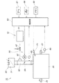
図1は本発明に係る汎用エンジンの燃焼系統の系統図であり、汎用エンジン10の燃焼系統の概要を示す。図2(a),(b)は本発明に係る汎用エンジンの構成図であり、(a)はクランク軸21の動力取出し部側から見た汎用エンジン10を示し、(b)は(a)とは反対側から見た汎用エンジン10を示す。
The best mode for carrying out the present invention will be described below with reference to the accompanying drawings.
FIG. 1 is a system diagram of a combustion system of a general-purpose engine according to the present invention, and shows an outline of a combustion system of a general-
図1及び図2に示すように、汎用エンジン10は、エンジン本体20に燃焼空気供給系30、燃料供給系40及び排気系50(図2参照)及び図示せぬ発電機等を一体的に組込んだエンジンユニットである。
エンジン本体20は、図2に示すように正面から見たとき、略水平なクランク軸21に対してシリンダ22を傾斜させた、傾斜シリンダ型のOHC式空冷型単気筒内燃機関である。
As shown in FIGS. 1 and 2, the general-
The
このような汎用エンジン10の始動方式には、リコイルスタータによる手動始動方式、又は、スタータモータによる自動始動方式を適宜選択して採用するものである。自己発電機能を有した汎用エンジン10なので、手動始動方式の場合にバッテリは必ずしも必要ない。自動始動方式の場合には、バッテリを組込めばよい。
図2において、23はリコイルスタータ始動用グリップ、51は排気系50に備えた排気用マフラである。
As a starting method of such a general-
In FIG. 2,
図1に示すように、燃焼空気供給系30は、エアクリーナ31から導入した燃焼空気を気化器32を介してエンジン本体20に供給する構成であり、気化器32にスロットル弁33を備える。
燃料供給系40は、燃料タンク41から気化器32に供給された燃料を、エンジン吸気負圧を利用して気化器32内に取り入れる構成である。気化器32に供給された燃料は噴霧されて燃焼空気と混合し、エンジン吸気口に入る。燃料供給系40に燃料遮断弁42を設けることで、メインスイッチ61(イグニッションスイッチ等の電源スイッチ61)にてエンジン本体20を停止させたときに、燃料遮断弁42を閉じて燃料の供給を遮断することができる。
As shown in FIG. 1, the combustion
The
スロットル弁33は、電子式ガバナ60(電気式ガバナ60とも言う。)によって開閉制御するものである。つまり、電子式ガバナ60は、現実のエンジン回転数(クランク軸21の回転数)を、メモリ62に記憶された「エンジン仕様データ」に基づくエンジン目標回転数となるように、制御部63によってスロットル弁33の開度を制御する構成である。
The
より詳しく述べると、制御部63は、メインスイッチ61がオン状態であるときに、エンジン回転センサ64で検出したエンジン回転数と、スロットルポジションセンサ65で検出したスロットル弁33の開度と、手動で調整するガバナ特性調整手段66の設定値とに基づいて、制御モータ67の回転を制御する構成である。制御モータ67は、制御部63の制御信号を受けてスロットル弁33を開閉駆動することで、開度を調整するスロットルモータであり、例えば制御部63のPWM信号によって作動する直流モータからなる。
スロットル弁33の開度に応じて、燃焼空気並びに燃料の各供給量を変化させることにより、現実のエンジン回転数をエンジン目標回転数に到達させることができる。
More specifically, when the
The actual engine speed can be made to reach the engine target speed by changing each supply amount of combustion air and fuel according to the opening of the
これらのメインスイッチ61、制御部63、この制御部63に組込まれたメモリ62、ガバナ特性調整手段66は汎用エンジン10に備えることになる。
メモリ62は、外部からの通信手段によって「エンジン仕様データ」を書き込み可能な構成であり、例えばRAM(ランダムアクセスメモリ)からなる。
ガバナ特性調整手段66は、メモリ62に記憶された「エンジン仕様データ」に基づくエンジン出力特性(回転特性)を、必要に応じて微調整するものであり、例えばボリュームからなる。
The
The
The governor characteristic adjusting means 66 finely adjusts the engine output characteristic (rotation characteristic) based on the “engine specification data” stored in the
ところで、従来の汎用エンジンにおけるガバナは、遠心式ガバナ機構のような機械式を採用していた。このため、工場出荷前に作業者がガバナ特性、すなわち、エンジン出力特性を各汎用エンジン毎に調整する必要があるとともに、汎用エンジンが搭載される機器の種類毎に調整する必要があった。
これに対して本発明の汎用エンジン10は、電子式ガバナ60によるエンジン回転数のモード設定方式を採用したので、工場出荷前に作業者が個別に調整する必要がない。従って、調整工数を低減することができる。しかも、スロットル弁33の開度を制御部63にて一括制御することができるので、エンジン出力特性をきめ細かく設定することができる。
By the way, the governor in the conventional general-purpose engine employs a mechanical type such as a centrifugal governor mechanism. For this reason, it is necessary for an operator to adjust the governor characteristic, that is, the engine output characteristic for each general-purpose engine before shipment from the factory, and to adjust for each type of equipment on which the general-purpose engine is mounted.
On the other hand, the general-
さらに制御部63は、エンジン用点火装置71に点火指令を発することで、エンジン本体20を作動させるものである。なお、汎用エンジン10のセンサとしては、他に図示せぬ温度センサ(潤滑油、吸気温、排気温、エンジン壁温等の検出センサ)、エンジン潤滑油用レベルセンサ等がある。
Further, the
図3は本発明に係る汎用エンジンと汎用エンジンを搭載する機器との関係を示す説明図である。図3に示すように、本発明の汎用エンジン10・・・は、低出力の小型エンジンから高出力の大型エンジンまで複数の種類がある。なお、この図3では3種類の汎用エンジン10・・・だけを示し、便宜的に、小型の汎用エンジン10のことを特に小型エンジン10Sと言い、中型の汎用エンジン10のことを特に小型エンジン10Mと言い、大型の汎用エンジン10のことを特に大型エンジン10Lと言うことにする。
FIG. 3 is an explanatory view showing the relationship between the general-purpose engine according to the present invention and a device equipped with the general-purpose engine. As shown in FIG. 3, the general-
これらの汎用エンジン10・・・は、搭載する相手の機器に合わせて、取付け姿勢を360°自由に傾けることが可能な、自在傾斜型エンジンである。従って、汎用エンジン10・・・をあらゆる機器に搭載することができる。例えば、除雪機81、芝刈機82、発電機83、図示せぬ運搬車等の各種の作業機にも、汎用エンジン10S,10M,10L,・・・を搭載することができる。作業機81,82,83,・・・で要求したエンジン出力特性を有している汎用エンジン10S,10M,10L,・・・を、適宜選択して搭載すればよい。
These general-
次に、上記構成の汎用エンジン10の完成検査装置及び完成検査方法について、図4〜図8に基づき説明する。汎用エンジン完成検査装置及び汎用エンジン完成検査方法は、組立てられた汎用エンジン10が所定の性能を有していることを検査するものである。
Next, a completion inspection device and a completion inspection method for the general-
図4は本発明に係る汎用エンジン完成検査装置の模式図である。図5は本発明に係るデータベースの概念の一例を示す説明図である。
図4に示すように、汎用エンジン完成検査装置100は搬送コンベア101、識別コード読取り機102、サーバ103、完成検査機104及び機器対応検査機105を主要な構成部材とした構成である。
FIG. 4 is a schematic view of a general-purpose engine completion inspection apparatus according to the present invention. FIG. 5 is an explanatory diagram showing an example of the concept of the database according to the present invention.
As shown in FIG. 4, the general-purpose engine
搬送コンベア101は、組立後の完成品からなる複数の各汎用エンジン10・・・を、図4に示す検査場所へ順次搬入するとともに検査が完了した後に搬出する装置である。
The
識別コード読取り機102は、各汎用エンジン10・・・に付されている識別コード91・・・を読取る手段であって、例えばバーコードリーダ(バーコード読取り機)等の光学的な読取り手段からなる。識別コード91・・・は、各汎用エンジン10・・・の1つ1つに個別に付された製品識別符号(識別情報)であり、例えばタグに付されたバーコードからなる。この識別コード91には、汎用エンジン10の製造番号、この汎用エンジン10を搭載する機器の種別、出荷先等の各種情報を付してある。
The
サーバ103は、データベースDBを保管するものである。データベースDBは、各汎用エンジン10・・・の単体としての「エンジン基本仕様データ」、並びに、汎用エンジン10・・・が搭載される作業機等の機器に基づく「機器対応エンジン仕様データ」を、識別コード91・・・に対応させて収納したものである。
なお、エンジン基本仕様データ並びに機器対応エンジン仕様データは、上記「エンジン仕様データ」のことである。
The
The engine basic specification data and the device-specific engine specification data are the above-mentioned “engine specification data”.
エンジン基本仕様データは、個々の汎用エンジン10自体における基本的な出力特性のデータ(各種のパラメータを含む)、すなわち基本的な性能であり、例えばエンジンの最低回転数、最高回転数、加速・減速特性、回転数に対する出力などである。
機器対応エンジン仕様データは、搭載される機器で要求する特性のデータ(各種のパラメータを含む)であり、例えば図1に示す電子式ガバナ60のガバナ特性(ガバナモード)、エンジン用潤滑油レベルに基づくオイルアラートモード、エンジンの設定回転数などである。
The basic engine specification data is basic output characteristic data (including various parameters) of each general-
The equipment-specific engine specification data is data of characteristics required by the equipment to be installed (including various parameters). For example, the governor characteristics (governor mode) of the
ここで、データベースDBの一例を示すと、次の通りである。図4及び図5に示すように、識別コード91・・・には汎用エンジン10・・・の各製造番号E1,E2,E3,・・・と、これらの汎用エンジン10・・・を搭載する機器の種別(搭載機器の種別)M1,M2,M3,・・・の情報が含まれている。
Here, an example of the database DB is as follows. As shown in FIG. 4 and FIG. 5, the
データベースは、汎用エンジン10の製造番号と搭載機器の種別とに対応した「エンジン基本仕様データDe1,De2,・・・」、並びに、「機器対応エンジン仕様データDm11,Dm21,・・・」を、例えばマップとして収納した情報形態である。 The database stores “engine basic specification data De1, De2,...” And “device compatible engine specification data Dm11, Dm21,. For example, it is an information form stored as a map.
エンジン基本仕様データは、汎用エンジン10の製造番号が同一であれば、搭載機器の種別にかかわらず、常に同じである。例えば、汎用エンジン10の製造番号がE1であれば、エンジン基本仕様データは常にDe1である。
一方、機器対応エンジン仕様データは、汎用エンジン10の製造番号と搭載機器の種別との組合せによって異なる。例えば、E1とM1との組合せでは、機器対応エンジン仕様データはDm11であり、E3とM2との組合せでは、機器対応エンジン仕様データはDm32である。
If the serial number of the general-
On the other hand, the device-specific engine specification data varies depending on the combination of the serial number of the general-
図4に示すように、完成検査機104は、(1)識別コード読取り機102で読み取った識別コード91に基づいて、対応するエンジン基本仕様データ及び機器対応エンジン仕様データを、サーバ103内のデータベースDBから取り込み、(2)エンジン基本仕様データに基づいて汎用エンジン10の単体としての各種検査を行い、(3)メモリ62に機器対応エンジン仕様データを書き込むものである。
As shown in FIG. 4, the completion inspection machine 104 (1) based on the
図4に示すように、機器対応検査機105は、メモリ62に書き込まれている機器対応エンジン仕様データに基づき、汎用エンジン10を機器対応エンジンとしての作動確認検査するものである。
As shown in FIG. 4, the device-corresponding
汎用エンジン完成検査装置100を用いた汎用エンジン完成検査方法は、以下の通りである。図4及び図5を参照しつつ、図6〜図8に基づき汎用エンジン完成検査方法の各工程を説明する。図中、ST××はステップ番号を示す。特に説明がないステップ番号については、番号順に進行する。
A general-purpose engine completion inspection method using the general-purpose engine
図6は本発明に係る汎用エンジン完成検査方法の説明図(その1)であり、完成検査方法の前半のフローを示す。図7は本発明に係る汎用エンジン完成検査方法の説明図(その2)であり、完成検査方法の後半のフローを示す。 FIG. 6 is an explanatory diagram (part 1) of the general-purpose engine completion inspection method according to the present invention, and shows the first half flow of the completion inspection method. FIG. 7 is an explanatory diagram (part 2) of the general-purpose engine completion inspection method according to the present invention, and shows the latter half of the completion inspection method.
ST01;検査対象の汎用エンジン10に付されている識別コード91を識別コード読取り機102で読み取る(識別コード読取り工程)。ここで、読み取った識別コード91に含まれている情報については、仮に、汎用エンジンの製造番号がE1で、搭載機器の種別がM1であるとする。図5に示すように、E1とM1との組合せでは、エンジン基本仕様データはDe1であり、機器対応エンジン仕様データはDm11である。
ST01: The
このように、識別コード91をバーコードで構成し、識別コード読取り工程ST01において、バーコードをバーコードリーダ等の光学的な読取り手段102によって読み取るようにした。
なお、識別コード読取り工程ST01には、識別コード読取り機102による読み取りの他に、検査作業者がキーボード操作をする等の手作業によって、識別コード91を直接に入力するなどの読み取りを含む。
In this way, the
The identification code reading step ST01 includes reading by directly inputting the
ST02;次に、完成検査機104からサーバ103に指令を発することで、読み取った識別コード91を検索キーとして、データベースDBからエンジン基本仕様データDe1並びに機器対応エンジン仕様データDm11を検索する。そして、読み取った識別コード91に基づき、エンジン基本仕様データDe1並びに機器対応エンジン仕様データDm11を、データベースDBから完成検査機104に自動的に取り込む(エンジン仕様データ取込み工程)。
ST02: Next, by issuing a command from the
ST03;次に、完成検査機104に通信ケーブル104aで汎用エンジン10の接続端子92を接続する(ケーブル接続工程)。このケーブル接続工程ST03は、検査作業者が実行又は自動的に実行する。
ST04;次に、汎用エンジン10の各センサ及び各スイッチ系統を、完成検査機104で自動的に検査する(センサ・スイッチ系統検査工程)。
ST03: Next, the
ST04: Next, each sensor and each switch system of the general-
ST05;センサ・スイッチ系統検査工程ST04で合格した汎用エンジン10については、完成検査機104によって、汎用エンジン10の制御部63を、エンジン基本仕様データDe1に基づく検査モードに自動的に切り替える(単体検査モード切替工程)。つまり、単体検査モード切替工程ST05は、ケーブル接続工程ST03及びセンサ・スイッチ系統検査工程ST04の後に、実行する。なお、この段階で、メモリ62にはデータが全く記憶されていない。
ST05: For the general-
ST06;単体検査モード切替工程ST05の後に、汎用エンジン10を始動させる(第1回エンジン始動工程)。この第1回エンジン始動工程ST06は、検査作業者が実行又は自動的に実行する。
ST07;次に、エンジン基本仕様データDe1に基づくエンジン作動目標指令信号を、完成検査機104から制御部63に発することで、この制御部63にて汎用エンジン10を所定の作動目標で作動させる(エンジン作動目標指令工程)。
ST08;汎用エンジン10が作動目標で作動した結果、得られた作動データを、制御部63から完成検査機104に発する(エンジン作動データ取得工程)。
ST06: After the single inspection mode switching step ST05, the general-
ST07: Next, by issuing an engine operation target command signal based on the engine basic specification data De1 from the
ST08: The operation data obtained as a result of the operation of the general-
ST09;エンジン作動目標指令に対する作動データを、完成検査機104で比較して性能を評価する(エンジン性能評価工程)。
例えば、作動目標がエンジン回転数である場合には、作動データは実測されたエンジン回転数及びスロットル弁の開度である。図1に示すように、実測のエンジン回転数はエンジン回転センサ64で検出し、実測のスロットル弁33の開度はスロットルポジションセンサ65で検出すればよい。
ST09: The operation data for the engine operation target command is compared by the
For example, when the operation target is the engine speed, the operation data is the actually measured engine speed and the opening of the throttle valve. As shown in FIG. 1, the actually measured engine speed may be detected by the
このように、ST07〜ST09からなる組合せ工程は、第1回エンジン始動工程ST06の後に、完成検査機104によってエンジン基本仕様データDe1に基づき、汎用エンジン10の単体としての各種検査を自動的に行う、「エンジン単体作動検査工程」である。
As described above, in the combination process consisting of ST07 to ST09, after the first engine start process ST06, the
エンジン単体作動検査工程ST07〜ST09によれば、完成検査機104から制御部63へ発したエンジン作動目標指令信号に基づいて汎用エンジン10を作動させ、その結果得られた作動データを制御部63から完成検査機104へ発し、エンジン作動目標指令に対する作動データを比較することで、性能を評価するようにしたので、エンジン単体の性能を、より確実に且つ正確に検査することができる。
According to the engine unit operation inspection steps ST07 to ST09, the general-
上記エンジン単体作動検査の概念の一例を、図8に示す。図8は本発明に係るエンジン単体作動検査工程の概念を説明する説明図であり、横軸を時間とし、縦軸を汎用エンジンの回転数として、エンジン回転数の追従性を示す。Niは汎用エンジンのアイドリング回転数である。 An example of the concept of the engine single operation check is shown in FIG. FIG. 8 is an explanatory view for explaining the concept of the engine single-unit operation inspection process according to the present invention, in which the horizontal axis represents time and the vertical axis represents the rotational speed of a general-purpose engine, and shows the followability of the engine speed. Ni is the idling speed of the general-purpose engine.
図6を参照しつつ説明すると、細線は汎用エンジンの回転数指示値を示し、ST07において汎用エンジンを作動させる作動目標に相当する。太線は汎用エンジンの実測値を示し、ST08において汎用エンジンが作動目標で作動した結果、得られた作動データに相当する。
図8に示すように、回転数指示値の変化に対して実測値の変化が概ね合致している。このように、回転数指示値に実測値が追従している場合には、ST09での評価は合格である。つまり、図4に示す制御部63並びに汎用エンジン10が、共に確実に追従して作動すると評価する。
Referring to FIG. 6, the thin line indicates the rotation speed instruction value of the general-purpose engine, and corresponds to the operation target for operating the general-purpose engine in ST07. A thick line indicates an actual measurement value of the general-purpose engine, and corresponds to operation data obtained as a result of the general-purpose engine operating at the operation target in ST08.
As shown in FIG. 8, the change in the actual measurement value substantially matches the change in the rotation speed instruction value. Thus, when the actual measurement value follows the rotation speed instruction value, the evaluation in ST09 is acceptable. That is, it is evaluated that the
ここで、図6に戻って説明を続ける。
ST10;エンジン性能評価工程ST09の後、すなわち、エンジン単体作動検査工程ST07〜ST09を完了した後に、汎用エンジン10を一旦停止させる(第1回エンジン停止工程)。その後に図7のST11に進む。
ST11;エンジン単体作動検査工程ST07〜ST09で合格した汎用エンジン10については、第1回エンジン停止工程ST10の後に、完成検査機104からメモリ62に、機器対応エンジン仕様データDm11を自動的に書き込む(総合仕様データ書込み工程)。
ST12;総合仕様データ書込み工程ST11の後に、汎用エンジン10から通信ケーブル104aを外す(ケーブル取外し工程)。このケーブル取外し工程ST12は、検査作業者が実行又は自動的に実行する。
Here, returning to FIG.
ST10: After the engine performance evaluation step ST09, that is, after completing the engine unit operation inspection steps ST07 to ST09, the general-
ST11: For the general-
ST12: After the general specification data writing step ST11, the
ST13;ケーブル取外し工程ST12の後に、汎用エンジン10を再始動させる(第2回エンジン始動工程)。
ST14;第2回エンジン始動工程ST13の後に、メモリ62に書き込まれている機器対応エンジン仕様データDm11に基づき、機器対応検査機105で汎用エンジン10を機器対応エンジンとしての作動確認をする(機器対応エンジン検査工程)。作動音やノイズ信号等の状態についても機器対応検査機105で検査する。
ST15;機器対応エンジン検査工程ST14を完了した後に、汎用エンジン10を停止させる(第2回エンジン停止工程)。
以上で完成検査を完了し、次の梱包工程に送る。
ST13: After the cable removing step ST12, the general-
ST14: After the second engine start step ST13, based on the device-compatible engine specification data Dm11 written in the
ST15: After the equipment-compatible engine inspection step ST14 is completed, the general-
This completes the final inspection and sends it to the next packaging process.
このように、ST04〜ST10からなる組合せ工程は、汎用エンジン10の単体としての各種検査を行う、「エンジン単体検査工程」である。ST13〜ST15からなる組合せ工程は、メモリ62に機器対応エンジン仕様データが書き込まれた汎用エンジン10の作動確認をする、「作動確認検査工程」である。
As described above, the combination process including ST04 to ST10 is an “engine unit inspection step” in which various inspections as a single unit of the general-
以上の説明をまとめると、次の通りである。
本発明の汎用エンジン完成検査装置100及び汎用エンジンの検査方法によれば、各汎用エンジン10に個別に付されている識別コード91を読み取り、この識別コード91を検索キーとして(1)検査対象の汎用エンジン10の「エンジン基本仕様データDe1」及び(2)この汎用エンジン10が搭載される機器に基づく「機器対応エンジン仕様データDm11」を、データベースDBから完成検査機104に自動的に取り込み、その後、完成検査機104と汎用エンジン10の制御部63との間で通信しつつ、完成検査機104に取り込まれたエンジン基本仕様データDe1に基づいて、汎用エンジン10の単体としての各種検査を自動的に実行するようにした。
これらのデータDe1,Dm11は予め設定されたものであり、一定の検査条件としても用いることができる。
The above description is summarized as follows.
According to the general-purpose engine
These data De1 and Dm11 are set in advance and can be used as constant inspection conditions.
このような一連の検査手順を実行することによって、完成検査機104と汎用エンジン10の制御部63との間で通信しつつ、エンジン基本仕様データDe1という一定の検査条件に基づいて、汎用エンジン単体としての基本的な性能を、自動的に検査することができる。従って、汎用エンジン単体の検査結果の精度を高めることができる。
By executing such a series of inspection procedures, the general-purpose engine alone is communicated between the
エンジン単体作動検査工程で合格した汎用エンジン10については、メモリ62に完成検査機104から「機器対応エンジン仕様データDm11」を書き込んだ後に、その汎用エンジン10が、搭載される機器で要求する出力特性を有しているか否かについて、確認検査を実行するようにした。
機器対応エンジン仕様データDm11が書き込まれた汎用エンジン10は、搭載される機器で要求する出力特性になるように、自己制御することができる。このため、搭載される機器で要求する出力特性になるように、検査員が調整する必要はない。また、確認検査については、上記完成検査機104又は別の機器対応検査機105によって実行すればよい。
For the general-
The general-
このように、機器対応エンジン仕様データDm11の書き込み及び確認検査という、一連の手順を実行することによって、汎用エンジン10を機器対応エンジン仕様に設定するとともに、その確認検査を効率良く行うことができるとともに、検査結果の精度を高めることができる。
As described above, by executing a series of procedures of writing the device-compatible engine specification data Dm11 and the confirmation check, the general-
このように本発明では、汎用エンジン10の完成検査方法において、検査結果の精度を高めることができるとともに、迅速に検査を行うことができ、検査コストを低減させることができる。
しかも、エンジン単体検査で合格した汎用エンジン10については、汎用エンジン10のメモリ62に完成検査機104から「機器対応エンジン仕様データDm11」を書き込むようにしたので、各機器に対応する、制御部63やメモリ62を予め準備しておく必要がない。このため、各々1種類の制御部63やメモリ62を準備すればよいので、製造コストや保管コストを低減することができるとともに、保管スペースを削減することができる。
As described above, according to the present invention, in the completion inspection method of the general-
In addition, for the general-
さらに本発明では、識別コード読取り工程ST01において、識別情報が記録されたバーコードからなる識別コード91を、バーコードリーダ等の光学的な読取り手段102(識別コード読取り機102)によって読み取るようにしたので、検査対象の汎用エンジン10に関する情報を、極めて迅速に且つ正確に取り入れることができる。
Furthermore, in the present invention, in the identification code reading step ST01, the
さらに本発明では、ケーブル接続工程ST03の後で且つ単体検査モード切替工程ST05の前に、汎用エンジン10の各センサ及び各スイッチ系統を検査するセンサ・スイッチ系統検査工程ST04を有している。
このように、エンジン単体作動検査工程(ST07〜ST09)において汎用エンジン10の単体としての各種検査を行う前に、この汎用エンジン10自体が有している各センサ及び各スイッチ系統を予め検査することによって、エンジン単体作動検査工程による作動検査を、円滑に且つ確実に行うことができる。
Furthermore, the present invention includes a sensor / switch system inspection process ST04 for inspecting each sensor and each switch system of the general-
Thus, before performing various inspections as a single unit of the general-
本発明は、他種類の汎用エンジン10・・・を単体としての検査を行うとともに、その検査で合格した汎用エンジン10の出力特性を、搭載される機器に対応させて設定し、その後に作動確認をするようにしたので、あらゆる種類の機器に選択して搭載される他種類の汎用エンジン10・・・の検査に好適である。
In the present invention, other types of general-
10…汎用エンジン、60…電子式ガバナ、62…メモリ、63…制御部、81〜83…機器、91…識別コード、100…汎用エンジン完成検査装置、102…識別コード読取り機、103…サーバ、104…完成検査機、104a…通信ケーブル、105…機器対応検査機、DB…データベース、De1,De2,De3…エンジン基本仕様データ、Dm11,Dm21,Dm31…機器対応エンジン仕様データ、ST01…識別コード読取り工程、ST02…エンジン仕様データ取込み工程、ST03…ケーブル接続工程、ST04…センサ・スイッチ系統検査工程、ST05…単体検査モード切替工程、ST06…第1回エンジン始動工程、ST07〜ST09…エンジン単体作動検査工程、ST07…作動目標指令工程、ST08…エンジン作動データ取得工程、ST09…エンジン性能評価工程、ST10…第1回エンジン停止工程、ST11…総合仕様データ書込み工程、ST12…ケーブル取外し工程、ST13…第2回エンジン始動工程、ST14…機器対応エンジン検査工程、ST15…第2回エンジン停止工程。
DESCRIPTION OF
Claims (4)
前記汎用エンジンに付されている製造番号等の識別コードを読み取る識別コード読取り工程と、
読み取った前記識別コードに基づき、前記汎用エンジンの単体としてのエンジン基本仕様データ、並びに、汎用エンジンが搭載される作業機等の機器に基づく機器対応エンジン仕様データを、データベースから完成検査機に取り込むエンジン仕様データ取込み工程と、
前記完成検査機に通信ケーブルで前記汎用エンジンを接続するケーブル接続工程と、
このケーブル接続工程の後に、前記完成検査機によって、前記汎用エンジンの制御部を、前記エンジン基本仕様データに基づく検査モードに切り替える単体検査モード切替工程と、
この単体検査モード切替工程の後に、前記汎用エンジンを始動させる第1回エンジン始動工程と、
この第1回エンジン始動工程の後に、前記完成検査機によって前記エンジン基本仕様データに基づき、前記汎用エンジンの単体としての各種検査を行うエンジン単体作動検査工程と、
このエンジン単体作動検査工程を完了した後に、前記汎用エンジンを一旦停止させる第1回エンジン停止工程と、
この第1回エンジン停止工程の後に、前記完成検査機から前記制御部のメモリに、前記機器対応エンジン仕様データを書き込む総合仕様データ書込み工程と、
この総合仕様データ書込み工程の後に、前記汎用エンジンから前記通信ケーブルを外すケーブル取外し工程と、
このケーブル取外し工程の後に、前記汎用エンジンを再始動させる第2回エンジン始動工程と、
この第2回エンジン始動工程の後に、前記メモリに書き込まれている機器対応エンジン仕様データに基づき、前記汎用エンジンを機器対応エンジンとしての作動確認検査する機器対応エンジン検査工程と、
この機器対応エンジン検査工程を完了した後に、前記汎用エンジンを停止させる第2回エンジン停止工程と、
を有していることを特徴とした汎用エンジン完成検査方法。 In the general-purpose engine completion inspection method for inspecting that the assembled general-purpose engine has a predetermined performance, the general-purpose engine completion inspection method includes:
An identification code reading step of reading an identification code such as a production number attached to the general-purpose engine;
An engine that imports engine basic specification data as a single unit of the general-purpose engine and engine-compatible engine specification data based on a device such as a work machine on which the general-purpose engine is installed into a complete inspection machine based on the read identification code. Specification data capture process,
A cable connection step of connecting the general-purpose engine to the completion inspection machine with a communication cable;
After this cable connection step, by the completion inspection machine, the control unit of the general-purpose engine, a single inspection mode switching step for switching to an inspection mode based on the engine basic specification data,
After the single inspection mode switching step, a first engine starting step of starting the general-purpose engine,
After this first engine start process, based on the engine basic specification data by the completion inspection machine, an engine unit operation inspection process for performing various inspections as a single unit of the general-purpose engine,
A first engine stop step for temporarily stopping the general-purpose engine after completing the engine unit operation inspection step;
After the first engine stop step, a general specification data writing step for writing the device-specific engine specification data from the completion inspection machine to the memory of the control unit;
After this general specification data writing step, a cable removal step of removing the communication cable from the general-purpose engine,
A second engine starting step of restarting the general-purpose engine after the cable removing step;
After the second engine start process, based on the equipment-compatible engine specification data written in the memory, an equipment-compatible engine inspection process for checking the operation of the general-purpose engine as an equipment-compatible engine;
A second engine stop step for stopping the general-purpose engine after completing the equipment-compatible engine inspection step;
A general-purpose engine completion inspection method characterized by comprising:
前記エンジン基本仕様データに基づくエンジン作動目標指令信号を、前記完成検査機から前記制御部に発することで、この制御部にて前記汎用エンジンを所定の作動目標で作動させるエンジン作動目標指令工程と、
前記汎用エンジンが前記作動目標で作動した結果、得られた作動データを、前記制御部から前記完成検査機に発するエンジン作動データ取得工程と、
前記エンジン作動目標指令に対する前記作動データを、前記完成検査機で比較して性能を評価するエンジン性能評価工程と、
からなることを特徴とした請求項1記載の汎用エンジン完成検査方法。 The engine unit operation inspection process includes:
An engine operation target command signal based on the engine basic specification data is issued from the completion inspection machine to the control unit, and the control unit operates the general-purpose engine with a predetermined operation target; and
Engine operation data acquisition step of issuing the operation data obtained as a result of the operation of the general purpose engine at the operation target from the control unit to the completion inspection machine,
An engine performance evaluation step for evaluating the performance by comparing the operation data for the engine operation target command with the completion inspection machine;
The general-purpose engine completion inspection method according to claim 1, comprising:
3. The identification code according to claim 1, wherein the identification code comprises a barcode, and the barcode is read by an optical reading means such as a barcode reader in the identification code reading step. 3. The general-purpose engine completion inspection method according to 3.
Priority Applications (3)
| Application Number | Priority Date | Filing Date | Title |
|---|---|---|---|
| JP2005182988A JP4471292B2 (en) | 2005-06-23 | 2005-06-23 | General-purpose engine completion inspection method |
| US11/448,694 US7458255B2 (en) | 2005-06-23 | 2006-06-07 | Industrial engine completion inspection method |
| FR0652615A FR2887647B1 (en) | 2005-06-23 | 2006-06-23 | METHOD FOR CONTROLLING THE COMPLETION OF AN INDUSTRIAL ENGINE |
Applications Claiming Priority (1)
| Application Number | Priority Date | Filing Date | Title |
|---|---|---|---|
| JP2005182988A JP4471292B2 (en) | 2005-06-23 | 2005-06-23 | General-purpose engine completion inspection method |
Publications (2)
| Publication Number | Publication Date |
|---|---|
| JP2007003318A JP2007003318A (en) | 2007-01-11 |
| JP4471292B2 true JP4471292B2 (en) | 2010-06-02 |
Family
ID=37563206
Family Applications (1)
| Application Number | Title | Priority Date | Filing Date |
|---|---|---|---|
| JP2005182988A Expired - Fee Related JP4471292B2 (en) | 2005-06-23 | 2005-06-23 | General-purpose engine completion inspection method |
Country Status (3)
| Country | Link |
|---|---|
| US (1) | US7458255B2 (en) |
| JP (1) | JP4471292B2 (en) |
| FR (1) | FR2887647B1 (en) |
Families Citing this family (2)
| Publication number | Priority date | Publication date | Assignee | Title |
|---|---|---|---|---|
| JP4819733B2 (en) * | 2007-03-30 | 2011-11-24 | 本田技研工業株式会社 | General-purpose internal combustion engine |
| USD749511S1 (en) | 2013-07-10 | 2016-02-16 | Champion Power Equipment, Inc. | Engine powered generator |
Family Cites Families (6)
| Publication number | Priority date | Publication date | Assignee | Title |
|---|---|---|---|---|
| JPS55147331A (en) * | 1979-05-07 | 1980-11-17 | Toyota Central Res & Dev Lab Inc | Engine analyzer |
| JP3767875B2 (en) * | 1997-11-13 | 2006-04-19 | 株式会社小松製作所 | Engine abnormality detection device and abnormality detection method |
| JP2002244724A (en) * | 2001-02-20 | 2002-08-30 | Honda Motor Co Ltd | Machine remote monitoring device and management method |
| US6650977B2 (en) * | 2001-08-01 | 2003-11-18 | International Truck Intellectual Property Company, Llc | Automated vehicle inspection system |
| JP2003228409A (en) | 2002-02-05 | 2003-08-15 | Toyota Motor Corp | Sampling inspection instruction system, sampling inspection instruction method, and sampling inspection instruction program |
| US6886422B2 (en) * | 2002-10-09 | 2005-05-03 | General Electric Co. | Methods and apparatus for inspecting components |
-
2005
- 2005-06-23 JP JP2005182988A patent/JP4471292B2/en not_active Expired - Fee Related
-
2006
- 2006-06-07 US US11/448,694 patent/US7458255B2/en not_active Expired - Fee Related
- 2006-06-23 FR FR0652615A patent/FR2887647B1/en not_active Expired - Fee Related
Also Published As
| Publication number | Publication date |
|---|---|
| FR2887647A1 (en) | 2006-12-29 |
| JP2007003318A (en) | 2007-01-11 |
| US20070000314A1 (en) | 2007-01-04 |
| FR2887647B1 (en) | 2014-06-20 |
| US7458255B2 (en) | 2008-12-02 |
Similar Documents
| Publication | Publication Date | Title |
|---|---|---|
| US5585553A (en) | Apparatus and method for diagnosing an engine using a boost pressure model | |
| US9429092B2 (en) | Fault detection and response techniques | |
| EP1693661B1 (en) | Test equipment of engine motoring | |
| JP2002323409A (en) | Vehicle management system | |
| CN104047794A (en) | Engine knock detection system and method | |
| MX2013009724A (en) | Method for functionally testing turbomachines, and test device therefor. | |
| US20060277907A1 (en) | Malfunction detection apparatus for pressure sensor | |
| US10102690B2 (en) | Non-starting engine remote diagnostic | |
| CN110685830A (en) | Method, device, equipment and storage medium for detecting excessive valve control deviation | |
| JP4471292B2 (en) | General-purpose engine completion inspection method | |
| US11401881B2 (en) | Fourier diagnosis of a charge cycle behavior of an internal combustion engine | |
| US5040117A (en) | Automatically adjusting the emissions from an idling engine | |
| KR101537540B1 (en) | Method and control device for detecting the direction of rotation of a drive shaft of an internal combustion engine for a motor vehicle | |
| CN113167679A (en) | Test bench with test piece model | |
| EP1779209B1 (en) | Engine control module and method for use in engine system manufacture | |
| CN108572077A (en) | A vehicle engine detection system | |
| KR100364892B1 (en) | System and method for testing engines of vehicles | |
| CN113825995A (en) | Method for real-time analysis of internal processes of an engine | |
| JP2010112351A (en) | Engine testing apparatus | |
| JP4102576B2 (en) | Compression top dead center detector for the engine under test | |
| CN107842432A (en) | Method for identifying the leakage in air inlet pipe | |
| JPH01265163A (en) | Measuring instrument for speed of revolution of engine | |
| JP2002322949A (en) | Vehicle management system | |
| KR20020053916A (en) | Apparatus and method for measuring cylinder compression pressure of diesel engine for a vehicle | |
| JP2002322937A (en) | Vehicle management system |
Legal Events
| Date | Code | Title | Description |
|---|---|---|---|
| A621 | Written request for application examination |
Free format text: JAPANESE INTERMEDIATE CODE: A621 Effective date: 20071126 |
|
| A977 | Report on retrieval |
Free format text: JAPANESE INTERMEDIATE CODE: A971007 Effective date: 20091225 |
|
| TRDD | Decision of grant or rejection written | ||
| A01 | Written decision to grant a patent or to grant a registration (utility model) |
Free format text: JAPANESE INTERMEDIATE CODE: A01 Effective date: 20100224 |
|
| A01 | Written decision to grant a patent or to grant a registration (utility model) |
Free format text: JAPANESE INTERMEDIATE CODE: A01 |
|
| A61 | First payment of annual fees (during grant procedure) |
Free format text: JAPANESE INTERMEDIATE CODE: A61 Effective date: 20100226 |
|
| FPAY | Renewal fee payment (event date is renewal date of database) |
Free format text: PAYMENT UNTIL: 20130312 Year of fee payment: 3 |
|
| R150 | Certificate of patent or registration of utility model |
Ref document number: 4471292 Country of ref document: JP Free format text: JAPANESE INTERMEDIATE CODE: R150 Free format text: JAPANESE INTERMEDIATE CODE: R150 |
|
| FPAY | Renewal fee payment (event date is renewal date of database) |
Free format text: PAYMENT UNTIL: 20130312 Year of fee payment: 3 |
|
| FPAY | Renewal fee payment (event date is renewal date of database) |
Free format text: PAYMENT UNTIL: 20140312 Year of fee payment: 4 |
|
| LAPS | Cancellation because of no payment of annual fees |