JP4465935B2 - Head protection airbag device - Google Patents
Head protection airbag device Download PDFInfo
- Publication number
- JP4465935B2 JP4465935B2 JP2001269118A JP2001269118A JP4465935B2 JP 4465935 B2 JP4465935 B2 JP 4465935B2 JP 2001269118 A JP2001269118 A JP 2001269118A JP 2001269118 A JP2001269118 A JP 2001269118A JP 4465935 B2 JP4465935 B2 JP 4465935B2
- Authority
- JP
- Japan
- Prior art keywords
- airbag
- gas
- ejection hole
- width direction
- vehicle width
- Prior art date
- Legal status (The legal status is an assumption and is not a legal conclusion. Google has not performed a legal analysis and makes no representation as to the accuracy of the status listed.)
- Expired - Lifetime
Links
Images


Landscapes
- Air Bags (AREA)
Description
【0001】
【発明の属する技術分野】
本発明は、車両に装備される頭部保護エアバッグ装置、特に、折り畳まれた状態でルーフサイドレールに沿って収納されるエアバッグがピラーガーニッシュの上方を横切るように配置され、同エアバッグの膨張部に連通するガス通路にインフレータからディフューザを通してガスを供給可能に構成した頭部保護エアバッグ装置に関する。
【0002】
【従来の技術】
車両に装備される頭部保護エアバッグ装置では、折り畳まれた状態でルーフサイドレールに沿って収納されるエアバッグがピラーガーニッシュの上方を横切るように配置される構成が採用されていて、この構成は例えば米国特許第6,099,029号明細書に記載されている頭部保護エアバッグ装置にも採用されている。米国特許第6,099,029号明細書に記載されている頭部保護エアバッグ装置では、車両前後方向の略中央部にインフレータが配置され、同インフレータからホースとエアバッグのガス通路内に配設したダクトを通してガスがエアバッグの膨張部(前席用膨張部と後席用膨張部)に供給可能とされている。
【0003】
【発明が解決しようとする課題】
上記した従来の頭部保護エアバッグ装置では、折り畳まれて収納されているエアバッグが車室内の側壁に沿ってカーテン状に膨張展開可能であり、エアバッグの中央部(中間部)から前席用膨張部と後席用膨張部とにガスを供給するものであるため、エアバッグの前端部または後端部から前席用膨張部と後席用膨張部とにガスを供給するものに比して、エアバッグの展開完了までの時間を短縮することが可能であるものの、展開途中のエアバッグが、エアバッグの中間部に対応して配置されているピラーガーニッシュの上端部に引っ掛かったり、同ピラーガーニッシュとピラーとの間に潜り込むおそれがある。
【0004】
上記した問題(エアバッグの引っ掛かりや潜り込み)は、ピラーガーニッシュの上端部に対応してバッグ展開ガイド(ジャンプ台)を設けることでも解消し得るものの、かかる場合には、当該頭部保護エアバッグ装置の構成部品にバッグ展開ガイドを加える必要があって、組付性を悪化するおそれがあるばかりか、コストアップの要因ともなる。
【0005】
【課題を解決するための手段】
本発明は、上記した課題に対処すべく、折り畳まれた状態でルーフサイドレールに沿って収納されるエアバッグがピラーガーニッシュの上方を横切るように配置され、同エアバッグの膨張部に連通するガス通路にインフレータからディフューザを通してガスを供給可能に構成した頭部保護エアバッグ装置において、前記ディフューザの一部が車幅方向内側に向けて開口していてガスを噴射可能なガス噴出孔を有して前記ピラーガーニッシュに対応する前記エアバッグの一部内に配置されるとともに、折り畳まれた状態の前記エアバッグにおける前記ピラーガーニッシュに対応する部位が前記ガス噴出孔の車幅方向内側に配置されて、ルーフヘッドライニングにより被覆されるように構成し、かつ前記ディフューザにおける前記ガス噴出孔を有する部位の前後に位置する部位に、下方に向けて開口していてガスを噴射可能なガス噴出孔が設けられていること(請求項1に係る発明)に特徴がある。この場合において、折り畳まれた状態の前記エアバッグにおける下方に向けて開口している前記ガス噴出孔に対応する部位は、下方に向けて開口している前記ガス噴出孔の下方側に配置されていること(請求項2に係る発明)も可能である。また、これらの場合において、折り畳まれた状態の前記エアバッグにおける前記ピラーガーニッシュに対応する部位が、折り畳まれた状態の前記エアバッグにおける前記ピラーガーニッシュに対応する部位以外の部位よりも車幅方向内側かつ上方に配置されていること(請求項3に係る発明)、または、前記ディフューザの車幅方向内側に向けて開口している前記ガス噴出孔を有する部位が、車幅方向外側の湾曲した形状となっていて、下方に向けて開口している前記ガス噴出孔は、車幅方向内側に向けて開口している前記ガス噴出孔に比して、車幅方向内側に配置されていること(請求項4に係る発明)も可能である。
【0006】
また、本発明は、折り畳まれた状態でルーフサイドレールに沿って収納されるエアバッグがピラーガーニッシュの上方を横切るように配置され、同エアバッグの膨張部に連通するガス通路にインフレータからディフューザを通してガスを供給可能に構成した頭部保護エアバッグ装置において、前記ディフューザの一部が車幅方向内側に向けて開口していてガスを噴射可能なガス噴出孔を有して前記ピラーガーニッシュに対応する前記エアバッグの一部内に配置されるとともに、折り畳まれた状態の前記エアバッグにおける前記ピラーガーニッシュに対応する部位が前記ガス噴出孔の車幅方向内側に配置されて、ルーフヘッドライニングにより被覆されるように構成し、かつ前記ディフューザにおける前記ガス噴出孔を有する部位の前後に位置する部位に、前後方向に向けて開口していてガスを噴射可能なガス噴出孔が設けられていること(請求項5に係る発明)に特徴がある。この場合において、前記ディフューザの車幅方向内側に向けて開口している前記ガス噴出孔を有する部位に、折り畳まれた状態の前記エアバッグの一部を車幅方向で収容可能な凹部を設けること(請求項6に係る発明)も可能である。
【0007】
【発明の作用・効果】
本発明による頭部保護エアバッグ装置においては、車両の側突時またはロールオーバー時等において、インフレータからガスが噴出し、このガスがディフューザを通してエアバッグのガス通路に供給されると、このガス通路を通してエアバッグの膨張部にガスが供給されて、エアバッグが車室内の側壁に沿ってカーテン状に膨張展開する。
【0008】
ところで、本発明による頭部保護エアバッグ装置(請求項1に係る発明)においては、ディフューザの一部が車幅方向内側に向けて開口していてガスを噴射可能なガス噴出孔を有してピラーガーニッシュに対応するエアバッグの一部内に配置されるとともに、折り畳まれた状態のエアバッグにおけるピラーガーニッシュに対応する部位が車幅方向内側に向けて開口しているガス噴出孔の車幅方向内側に配置され、かつディフューザの車幅方向内側に向けて開口しているガス噴出孔を有する部位の前後に位置する部位に、下方に向けて開口していてガスを噴射可能なガス噴出孔が設けられているため、エアバッグが膨張展開する際には、ディフューザの車幅方向内側に向けて開口しているガス噴出孔から車幅方向内側に向けて噴射されるガスによって、エアバッグのピラーガーニッシュに対応する部位が車幅方向内側に押動されて、ルーフヘッドライニングが大きく押し開かれる。したがって、膨張展開途中のエアバッグは、ピラーガーニッシュに対応する部位を車幅方向内側に押されながら車室内の側壁に沿ってカーテン状に膨張展開することとなり、ピラーガーニッシュの上端部に引っ掛かり難く、同ピラーガーニッシュとピラーとの間に潜り込み難い。
【0009】
また、本発明による頭部保護エアバッグ装置(請求項1に係る発明)においては、ディフューザの一部(車幅方向内側に向けて開口しているガス噴出孔を有する部分)をピラーガーニッシュに対応するエアバッグの一部内に配置するとともに、折り畳まれた状態のエアバッグにおけるピラーガーニッシュに対応する部位を車幅方向内側に向けて開口しているガス噴出孔の車幅方向内側に配置し、かつディフューザの車幅方向内側に向けて開口しているガス噴出孔を有する部位の前後に位置する部位に、下方に向けて開口していてガスを噴射可能なガス噴出孔を設けることで実施できるものであり、バッグ展開ガイド(ジャンプ台)等の付加部品を必要としないため、構成部品の増加がなくて安価に実施することができる。
【0011】
【発明の実施の形態】
以下に、本発明の実施形態を図面に基づいて説明する。図1〜図6は本発明を乗用車系車両用の頭部保護エアバッグ装置に実施した一実施形態を示していて、この実施形態のエアバッグ装置は、車室側壁に沿ってカーテン状に膨張展開するエアバッグ11と、このエアバッグ11の前端部に組付けたテンションクロス12と、エアバッグ11のガス供給口11aにディフューザ13を介して気密的に組付けられるインフレータ14によって構成されるエアバッグモジュール10を備えている。
【0012】
エアバッグ11は、織目方向が前後上下となるように袋織によって形成されていて、表面に気密保持用のコーティングを施されており、前後方向の中間部位上端に設けたガス供給口11aと、このガス供給口11aの下端から前後方向に延びるガス通路11bと、このガス通路11bに上端にて連通する前席用膨張部11cおよび後席用膨張部11dを有するとともに、中間非膨張部11e、前端非膨張部11fおよび4個の取付片部11gを有している。なお、各取付片部11gには、ルーフサイドレール21への取付孔11g1が設けられている。
【0013】
前席用膨張部11cは、前席(Bピラー23に対応して配設されている座席)に着座する乗員の頭部(図示省略)を保護するもので、上下方向に延びる複数個の膨張室(図示省略のセル)を有している。一方、後席用膨張部11dは、後席に着座する乗員の頭部(図示省略)を保護するもので、上下方向に延びる複数個の膨張室(図示省略のセル)を有している。
【0014】
テンションクロス12は、エアバッグ11の構成布より薄くて安いノンコート織布によって三角形状(形状は適宜変更可能)に形成されていて、後端部12aにてエアバッグ11の前端非膨張部11fに縫合されており、前端部12bに設けた取付孔12b1にてAピラー22に組付けられる(図1参照)ようになっている。
【0015】
ディフューザ13は、図1〜図4にて示したように、先端部13aがT字状に形成され、基端部(ガス流入部)13bがJ字状に形成されたパイプであり、基端部13bにてインフレータ14のガス噴射口14aに設けた雄ねじ部14bにフレアナット15を用いて気密的かつ一体的に連結固定されている。また、ディフューザ13は、基端部13bの一部を除いてエアバッグ11内に収容されていて、エアバッグ11のガス供給口11aが締付バンド16を用いて気密的に組付けられている。ディフューザ13の先端部13aは、前後端を閉塞されていて、その下方部位には前後一対のガス噴射孔13a1,13a2が設けられ、またその略中央の車幅方向内側部位にはガス噴射孔13a3が設けられている。
【0016】
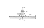
前後のガス噴射孔13a1,13a2は、図5にガス噴射孔13a1で例示したように、ディフューザ13における先端部13aの前後端部下面にてそれぞれ下方に向けて開口していて、エアバッグ11のガス通路11bを通して各膨張部11c,11dにガスを噴射供給可能である。一方、中央のガス噴射孔13a3は、図6に示したように、ディフューザ13における先端部13aの略中央側面にて車幅方向内側に向けて開口していて、車幅方向内側に向けてガスを噴射供給可能である。
【0017】
インフレータ14は、車両の側突時またはロールオーバー時等にガスをディフューザ13を通してエアバッグ11に向けて噴出供給するものであり、その外周に予め組付けたブラケット(図示省略)にて、ルーフサイドレール21にボルト等(図示省略)を用いて組付けられている。また、インフレータ14は、車両の前後方向略中央部においてエアバッグ11の上方にてルーフサイドレール21に沿って前後方向に配置されていて、折り畳まれた状態のエアバッグ11とともに、ルーフヘッドライニング31によって覆われるようになっている。
【0018】
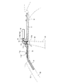
上記のように構成したこの実施形態のエアバッグ装置においては、通常時、エアバッグ11とテンションクロス12が上下方向にて例えば蛇腹折りで多重に折り畳まれて破断可能な結束テープ17(図2、図3および図4に一部を示した)にて保持された状態で、図2に示したように、Aピラー22とルーフサイドレール21に沿って収納されていて、Aピラーガーニッシュ32とルーフヘッドライニング31により被覆されている。
【0019】
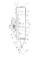
また、車両の側突時またはロールオーバー時等において、インフレータ14からガスが噴出し、このガスがディフューザ13を通して各ガス噴射孔13a1,13a2,13a3からエアバッグ11のガス通路11bに供給されると、エアバッグ11がルーフヘッドライニング31の該当部位を車室内に向けて変形させて下方に展開するとともに、テンションクロス12がAピラーガーニッシュ32の該当部位を車室内に向けて変形させて下方に展開し、エアバッグ11が図1にて示したように車室内の側壁に沿ってカーテン状に膨張展開する。この際には、エアバッグ11の各膨張部11c,11dが各乗員の頭部側方に位置する頭部保護エリアに向けて膨張展開する。
【0020】
ところで、この実施形態においては、図2〜図6に示したように、ディフューザ13の先端部13aの一部が車幅方向内側に向けて開口していてガスを噴射可能なガス噴出孔13a3を有してBピラーガーニッシュ33に対応するエアバッグ11の一部内に配置されるとともに、折り畳まれた状態のエアバッグ11におけるBピラーガーニッシュ33に対応する部位P1がガス噴出孔13a3の車幅方向内側にオフセット配置されて、ルーフヘッドライニング31により被覆され、かつディフューザ13のガス噴出孔13a3を有する部位の前後に位置する部位に下方に向けて開口していてガスを噴射可能なガス噴出孔13a1,13a2が設けられている。なお、Bピラーガーニッシュ33は、図6に示したように、クリップ41等を用いてBピラー23に組付けられている。
【0021】
このため、この実施形態では、エアバッグ11が膨張展開する際には、ディフューザ13のガス噴出孔13a3から車幅方向内側に向けて噴射されるガスによって、エアバッグ11のBピラーガーニッシュ33に対応する部位P1が車幅方向内側に押動されて、ルーフヘッドライニング31が大きく押し開かれる。したがって、膨張展開途中のエアバッグ11は、Bピラーガーニッシュ33に対応する部位P1を車幅方向内側に押されながら車室内の側壁に沿ってカーテン状に膨張展開することとなり、Bピラーガーニッシュ33の上端部33aに引っ掛かり難く、Bピラーガーニッシュ33とBピラー23との間に潜り込み難い。また、エアバッグ11の他の部位(部位P1以外の部位)では、ディフューザ13のガス噴出孔13a1,13a2から下方に向けて噴射されるガスによって、エアバッグ11を窓ガラス50(図5参照)に沿って適切に展開させることができる。
【0022】
また、この実施形態においては、ディフューザ13の一部(車幅方向内側に向けて開口しているガス噴出孔13a3を有する部分)をBピラーガーニッシュ33に対応するエアバッグ11の一部内に配置するとともに、折り畳まれた状態のエアバッグ11におけるBピラーガーニッシュ33に対応する部位P1をガス噴出孔13a3の車幅方向内側に配置し、かつディフューザ13のガス噴出孔13a3の前後に位置する部位にガス噴出孔13a1,13a2を設けることで実施できるものであり、バッグ展開ガイド(ジャンプ台)等の付加部品を必要としないため、構成部品の増加がなくて安価に実施することができる。
【0023】
上記実施形態においては、図4に示したように、折り畳まれた状態のエアバッグ11におけるBピラーガーニッシュ33に対応する部位P1が、他の部位よりも車幅方向内側に配置されるようにして、ガス噴射孔13a3の車幅方向内側に配置されるように実施したが、図7に示したように、ディフューザ13の先端部中央が車幅方向外側に湾曲した形状とすることによって、折り畳まれた状態のエアバッグ11におけるBピラーガーニッシュ対応部位P1がガス噴射孔13a3の車幅方向内側に配置されるようにして実施することも可能である。
【0024】
また、上記実施形態においては、図1〜図4に示したように、ディフューザ13の先端部13aをT字状として実施したが、図8および図9に示したように、ディフューザ13の先端部13aをI字状として実施することも可能である。図8および図9に示した実施形態のディフューザ13では、先端部13aに前後一対のガス噴射孔13a1,13a2とガス噴射孔13a3が設けられるとともに、ガス噴射孔13a3を有する部位に折り畳まれた状態のエアバッグ11の一部を車幅方向で収容可能な凹部13cが設けられている。このため、図8および図9に示した実施形態のエアバッグ装置では、車幅方向の寸法を小さくすることが可能であり、車両への搭載性を向上させることが可能である。
【0025】
また、上記実施形態においては、インフレータ14が車両の前後方向略中央部においてエアバッグ11の上方にてルーフサイドレール21に沿って前後方向に配置される頭部保護エアバッグ装置に本発明を実施したが、本発明は、図10にて示したように、インフレータ14が車両の後方に配置される頭部保護エアバッグ装置にも同様に実施可能である。なお、図10は後席が前後二列の三列席ミニバンに実施した実施形態を概略的に示している。
【0026】
図10に示した頭部保護エアバッグ装置においては、ディフューザ13がエアバッグ11の後端内から前端部内にまで延在していて、ディフューザ13の下面にはエアバッグ11の各膨張部(図示省略)にガスを噴射供給可能なガス噴射孔(上記実施形態のガス噴射孔13a1,13a2に相当するもの)が複数個設けられるとともに、ディフューザ13の車幅方向内側面には各ピラーガーニッシュ33,34に対応する部位にて車幅方向内側に向けてガスを噴射供給可能なガス噴射孔(上記実施形態のガス噴射孔13a3に相当するもの)が設けられている。このため、この実施形態においては、Bピラーガーニッシュ33の配設部位とCピラーガーニッシュ34の配設部位にて上記実施形態と同様の作用効果を得ることが可能である。
【0027】
また、上記実施形態においては、エアバッグ11として袋織バッグを採用したが、縫製バッグや接着(熱溶着)バッグを採用して実施することも可能である。また、上記実施形態においては、乗用車系車両用の頭部保護エアバッグ装置に本発明を実施したが、乗用車系以外の車両用頭部保護エアバッグ装置にも適宜変更して実施することが可能である。
【図面の簡単な説明】
【図1】 本発明による頭部保護エアバッグ装置(車両の右側に装着されるもの)の一実施形態を概略的に示す側面図である。
【図2】 図1に示したエアバッグとテンションクロスが折り畳まれた状態の概略的な側面図である。
【図3】 図2の要部拡大側面図である。
【図4】 図3の4−4線に沿った断面図である。
【図5】 図3の5−5線に沿った断面図である。
【図6】 図3の6−6線に沿った断面図である。
【図7】 本発明の他の実施形態を示す図4相当の平面図である。
【図8】 本発明のその他の実施形態を示す図3相当の側面図である。
【図9】 図8の9−9線に沿った断面図である。
【図10】 本発明をインフレータが車両の後方に配置される頭部保護エアバッグ装置に実施した場合の概略的な側面図である。
【符号の説明】
10…エアバッグモジュール、11…エアバッグ、11a…ガス供給口、11b…ガス通路、11c…前席用膨張部、11d…後席用膨張部、11e…中間非膨張部、11f…前端非膨張部、11g…取付片部、12…テンションクロス、13…ディフューザ、13a…先端部、13a1,13a2,13a3…ガス噴射孔、13b…基端部、13c…凹部、14…インフレータ、21…ルーフサイドレール、22…Aピラー、23…Bピラー、31…ルーフヘッドライニング、32…Aピラーガーニッシュ、33…Bピラーガーニッシュ、P1…エアバッグのBピラーガーニッシュ対応部位。[0001]
BACKGROUND OF THE INVENTION
The present invention relates to a head protection airbag device mounted on a vehicle, and in particular, an airbag stored along a roof side rail in a folded state is arranged so as to cross over a pillar garnish. The present invention relates to a head protecting airbag device configured to be able to supply gas from an inflator to a gas passage communicating with an inflating portion through a diffuser.
[0002]
[Prior art]
The head protection airbag device installed in the vehicle employs a configuration in which the airbag stored along the roof side rail in a folded state is arranged so as to cross over the pillar garnish. Is also employed in the head protection airbag device described in, for example, US Pat. No. 6,099,029. In the head protection airbag device described in US Pat. No. 6,099,029, an inflator is disposed at a substantially central portion in the vehicle front-rear direction, and the inflator is disposed in the gas passage between the hose and the airbag. Gas can be supplied to the inflatable portions of the airbag (the front seat inflatable portion and the rear seat inflatable portion) through the duct provided.
[0003]
[Problems to be solved by the invention]
In the above-described conventional head protection airbag device, the airbag stored in a folded state can be inflated and deployed in a curtain shape along the side wall of the vehicle interior, and the front seat from the central portion (intermediate portion) of the airbag Since gas is supplied to the inflatable portion for the rear seat and the inflatable portion for the rear seat, the gas is supplied to the inflatable portion for the front seat and the inflatable portion for the rear seat from the front end portion or the rear end portion of the airbag. Although it is possible to shorten the time until the airbag deployment is completed, the airbag in the middle of deployment is caught on the upper end of the pillar garnish arranged corresponding to the middle portion of the airbag, There is a risk of sinking between the pillar garnish and the pillar.
[0004]
The above-described problems (airbag catching and sinking) can be solved by providing a bag deployment guide (jump table) corresponding to the upper end of the pillar garnish. It is necessary to add a bag unfolding guide to these components, which may deteriorate the assembling property and also increase the cost.
[0005]
[Means for Solving the Problems]
In order to address the above-described problems, the present invention is arranged such that the airbag stored along the roof side rail in a folded state crosses over the pillar garnish and communicates with the inflating portion of the airbag. In the head protection airbag device configured to be able to supply gas from the inflator through the diffuser to the passage, a part of the diffuser is opened toward the inner side in the vehicle width direction and has a gas ejection hole through which gas can be injected. A portion corresponding to the pillar garnish in the airbag in a folded state is disposed in a part of the airbag corresponding to the pillar garnish, and is disposed on the inner side in the vehicle width direction of the gas ejection hole. configured to be covered by the head lining, and have the said gas ejection holes in the diffuser The site located before and after the site that is characterized in that the open can inject gas have a gas ejection hole is provided downward (the invention according to claim 1). In this case, the portion corresponding to the gas ejection hole that opens downward in the airbag in the folded state is disposed on the lower side of the gas ejection hole that opens downward. (Invention according to claim 2) is also possible. Further, in these cases, the portion corresponding to the pillar garnish in the folded airbag is more inward in the vehicle width direction than the portion other than the portion corresponding to the pillar garnish in the folded airbag. And the part which has the gas ejection hole which is arrange | positioned upwards (invention which concerns on Claim 3), or opens toward the vehicle width direction inner side of the said diffuser is the curved shape of the vehicle width direction outer side The gas ejection hole that opens downward is arranged on the inner side in the vehicle width as compared with the gas ejection hole that opens toward the inner side in the vehicle width direction ( The invention according to
[0006]
Further, according to the present invention, the airbag stored along the roof side rail in a folded state is disposed so as to cross over the pillar garnish, and the gas passage communicating with the inflating portion of the airbag is passed through the diffuser from the inflator. In the head protection airbag device configured to be able to supply gas, a part of the diffuser is open toward the inner side in the vehicle width direction, and has a gas ejection hole capable of injecting gas, and corresponds to the pillar garnish. A portion corresponding to the pillar garnish in the airbag in a folded state is disposed in a part of the airbag and is disposed on the inner side in the vehicle width direction of the gas ejection hole and covered with a roof head lining. And located before and after the portion having the gas ejection hole in the diffuser A site that is characterized in that the open can inject gas have a gas ejection hole is provided (the invention according to claim 5) toward the front-rear direction. In this case, a recessed portion capable of accommodating a part of the folded airbag in the vehicle width direction is provided at a portion having the gas ejection hole that opens toward the inner side in the vehicle width direction of the diffuser. (Invention according to claim 6 ) is also possible.
[0007]
[Operation and effect of the invention]
In the head protection airbag device according to the present invention, when a gas is ejected from the inflator at the time of a side collision or rollover of the vehicle, and this gas is supplied to the gas passage of the airbag through the diffuser, the gas passage Gas is supplied to the inflating portion of the air bag through the air bag, and the air bag is inflated and deployed in a curtain shape along the side wall in the passenger compartment.
[0008]
By the way, in the head protection airbag device according to the present invention (the invention according to claim 1), a part of the diffuser is opened toward the inner side in the vehicle width direction and has a gas ejection hole through which gas can be injected. Inside of the airbag corresponding to the pillar garnish, the inside of the gas outlet hole in the vehicle width direction where the portion corresponding to the pillar garnish in the folded airbag opens toward the inside in the vehicle width direction Is provided at the front and back of the part having the gas injection hole that opens toward the inner side in the vehicle width direction of the diffuser, and a gas injection hole that opens downward and can inject gas is provided. because it is, when the air bag is inflated and deployed from the gas ejection hole that opens inward in the vehicle width direction of the diffuser gas injected toward the inside in the vehicle width direction I, a portion corresponding to the pillar garnish of the airbag is pushed inward in the vehicle width direction, the roof head lining is pushed open large. Therefore, the airbag in the middle of inflating and deploying is inflated and deployed in a curtain shape along the side wall of the passenger compartment while being pushed inward in the vehicle width direction at the portion corresponding to the pillar garnish, and is not easily caught on the upper end of the pillar garnish. It is difficult to dive between the pillar garnish and the pillar.
[0009]
Further, in the head protection airbag device according to the present invention (the invention according to claim 1), a part of the diffuser (a portion having a gas ejection hole opened toward the inner side in the vehicle width direction) corresponds to the pillar garnish. A portion corresponding to the pillar garnish in the airbag in a folded state is disposed on the inner side in the vehicle width direction of the gas ejection hole opened toward the inner side in the vehicle width direction , and at a site toward the vehicle width direction inner side of the diffuser located around the site with gas ejection hole that opens, can be performed in Rukoto an opening to allow the injection of gas have a gas ejection hole downward Since no additional parts such as a bag deployment guide (jump base) are required, the number of components is not increased, and it can be implemented at low cost.
[0011]
DETAILED DESCRIPTION OF THE INVENTION
Embodiments of the present invention will be described below with reference to the drawings. 1 to 6 show an embodiment in which the present invention is applied to a head protection airbag device for a passenger vehicle system vehicle. The airbag device according to this embodiment is inflated in a curtain shape along a side wall of a passenger compartment. An airbag constituted by an
[0012]
The
[0013]
The front
[0014]
The
[0015]
1 to 4, the
[0016]
The front and rear gas injection holes 13a1 and 13a2 are opened downward on the lower surfaces of the front and rear end portions of the
[0017]
The inflator 14 supplies gas to the
[0018]
In the airbag apparatus according to this embodiment configured as described above, the
[0019]
Further, when the vehicle collides or rolls over, gas is ejected from the inflator 14, and this gas is supplied from the gas injection holes 13a1, 13a2, 13a3 to the
[0020]
By the way, in this embodiment, as shown in FIGS. 2 to 6, a part of the
[0021]
For this reason, in this embodiment, when the
[0022]
Further, in this embodiment, a part of the diffuser 13 (a part having a gas ejection hole 13a3 that opens toward the inner side in the vehicle width direction) is disposed in a part of the
[0023]
In the above embodiment, as shown in FIG. 4, the part P1 corresponding to the
[0024]
Moreover, in the said embodiment, as shown in FIGS. 1-4, although the front-end | tip
[0025]
Moreover, in the said embodiment, this invention is implemented to the head protection airbag apparatus with which the
[0026]
In the head protection airbag device shown in FIG. 10, the
[0027]
Moreover, in the said embodiment, although the bag-woven bag was employ | adopted as the
[Brief description of the drawings]
FIG. 1 is a side view schematically showing an embodiment of a head protecting airbag device (mounted on the right side of a vehicle) according to the present invention.
FIG. 2 is a schematic side view showing a state in which the airbag and the tension cloth shown in FIG. 1 are folded.
FIG. 3 is an enlarged side view of the main part of FIG.
4 is a cross-sectional view taken along line 4-4 of FIG.
FIG. 5 is a cross-sectional view taken along line 5-5 of FIG.
6 is a cross-sectional view taken along line 6-6 of FIG.
FIG. 7 is a plan view corresponding to FIG. 4 showing another embodiment of the present invention.
FIG. 8 is a side view corresponding to FIG. 3, showing another embodiment of the present invention.
9 is a cross-sectional view taken along line 9-9 of FIG.
FIG. 10 is a schematic side view when the present invention is applied to a head protection airbag device in which an inflator is disposed at the rear of a vehicle.
[Explanation of symbols]
DESCRIPTION OF
Claims (6)
前記ディフューザの一部が車幅方向内側に向けて開口していてガスを噴射可能なガス噴出孔を有して前記ピラーガーニッシュに対応する前記エアバッグの一部内に配置されるとともに、
折り畳まれた状態の前記エアバッグにおける前記ピラーガーニッシュに対応する部位が前記ガス噴出孔の車幅方向内側に配置されて、ルーフヘッドライニングにより被覆されるように構成し、かつ
前記ディフューザにおける前記ガス噴出孔を有する部位の前後に位置する部位に、下方に向けて開口していてガスを噴射可能なガス噴出孔が設けられていることを特徴とする頭部保護エアバッグ装置。An airbag that is stored along the roof side rail in a folded state is arranged so as to cross over the pillar garnish, and gas can be supplied from the inflator through the diffuser to the gas passage that communicates with the inflation portion of the airbag. In the head protection airbag device made,
A part of the diffuser is open toward the inside in the vehicle width direction and has a gas ejection hole capable of injecting gas, and is disposed in a part of the airbag corresponding to the pillar garnish,
A portion corresponding to the pillar garnish in the airbag in the folded state is disposed on the inner side in the vehicle width direction of the gas ejection hole , and is configured to be covered with a roof head lining ; and
A head protection airbag device characterized in that a gas ejection hole that opens downward and is capable of injecting gas is provided in a portion of the diffuser that is positioned before and after the portion having the gas ejection hole. .
前記ディフューザの一部が車幅方向内側に向けて開口していてガスを噴射可能なガス噴出孔を有して前記ピラーガーニッシュに対応する前記エアバッグの一部内に配置されるとともに、A part of the diffuser is open toward the inside in the vehicle width direction and has a gas ejection hole capable of injecting gas, and is disposed in a part of the airbag corresponding to the pillar garnish,
折り畳まれた状態の前記エアバッグにおける前記ピラーガーニッシュに対応する部位が前記ガス噴出孔の車幅方向内側に配置されて、ルーフヘッドライニングにより被覆されるように構成し、かつA portion of the airbag in a folded state corresponding to the pillar garnish is arranged on the inner side in the vehicle width direction of the gas ejection hole, and is configured to be covered with a roof head lining; and
前記ディフューザにおける前記ガス噴出孔を有する部位の前後に位置する部位に、前後方向に向けて開口していてガスを噴射可能なガス噴出孔が設けられていることを特徴とする頭部保護エアバッグ装置。A head protection airbag characterized in that a gas ejection hole that opens in the front-rear direction and is capable of injecting gas is provided in a portion of the diffuser that is positioned before and after the portion having the gas ejection hole. apparatus.
Priority Applications (1)
| Application Number | Priority Date | Filing Date | Title |
|---|---|---|---|
| JP2001269118A JP4465935B2 (en) | 2001-09-05 | 2001-09-05 | Head protection airbag device |
Applications Claiming Priority (1)
| Application Number | Priority Date | Filing Date | Title |
|---|---|---|---|
| JP2001269118A JP4465935B2 (en) | 2001-09-05 | 2001-09-05 | Head protection airbag device |
Publications (2)
| Publication Number | Publication Date |
|---|---|
| JP2003072509A JP2003072509A (en) | 2003-03-12 |
| JP4465935B2 true JP4465935B2 (en) | 2010-05-26 |
Family
ID=19094993
Family Applications (1)
| Application Number | Title | Priority Date | Filing Date |
|---|---|---|---|
| JP2001269118A Expired - Lifetime JP4465935B2 (en) | 2001-09-05 | 2001-09-05 | Head protection airbag device |
Country Status (1)
| Country | Link |
|---|---|
| JP (1) | JP4465935B2 (en) |
Families Citing this family (5)
| Publication number | Priority date | Publication date | Assignee | Title |
|---|---|---|---|---|
| DE602004021028D1 (en) | 2003-12-08 | 2009-06-18 | Autoliv Dev | VEHICLE AIRBAG DEVICE |
| DE102006014823B4 (en) * | 2006-03-29 | 2010-07-22 | Autoliv Development Ab | Airbag arrangement with curved gas distribution pipe |
| JP5001780B2 (en) * | 2007-10-09 | 2012-08-15 | 本田技研工業株式会社 | Airbag device for vehicle |
| JP2012148637A (en) * | 2011-01-18 | 2012-08-09 | Nippon Plast Co Ltd | Curtain airbag device |
| JP2012148638A (en) * | 2011-01-18 | 2012-08-09 | Nippon Plast Co Ltd | Curtain airbag device |
-
2001
- 2001-09-05 JP JP2001269118A patent/JP4465935B2/en not_active Expired - Lifetime
Also Published As
| Publication number | Publication date |
|---|---|
| JP2003072509A (en) | 2003-03-12 |
Similar Documents
| Publication | Publication Date | Title |
|---|---|---|
| US6962364B2 (en) | Curtain air bag assembly | |
| JP5012726B2 (en) | Head protection airbag device | |
| US6913281B2 (en) | Head-protection airbag device | |
| US7080853B2 (en) | Airbag for head-protecting airbag device | |
| US7163233B2 (en) | Head-protecting airbag | |
| JP2003034221A (en) | Diffuser structure of airbag device | |
| JP2002193065A (en) | Head protection airbag device | |
| JP4336072B2 (en) | Airbag | |
| JP2011126413A (en) | Side airbag device attached to seat | |
| JP2000033847A (en) | Head protection airbag device | |
| JP4465935B2 (en) | Head protection airbag device | |
| JP3671874B2 (en) | Head protection airbag device | |
| JP3506066B2 (en) | Head protection airbag device | |
| JP5435913B2 (en) | Airbag device | |
| JP3900787B2 (en) | Head protection airbag device | |
| JP4590804B2 (en) | Head protection airbag device | |
| JP2003081048A (en) | Head protection airbag device | |
| JP2003063348A (en) | Diffuser structure of airbag device | |
| JP2004224255A (en) | Airbag device | |
| JP3671870B2 (en) | Head protection airbag device | |
| JP4696417B2 (en) | Head protection airbag mounting structure | |
| JP4069791B2 (en) | Head protection airbag device | |
| JP3932961B2 (en) | Head protection airbag device | |
| JP4019963B2 (en) | Head protection airbag | |
| JP2002337646A (en) | Head protection airbag device |
Legal Events
| Date | Code | Title | Description |
|---|---|---|---|
| A621 | Written request for application examination |
Free format text: JAPANESE INTERMEDIATE CODE: A621 Effective date: 20080516 |
|
| A977 | Report on retrieval |
Free format text: JAPANESE INTERMEDIATE CODE: A971007 Effective date: 20090528 |
|
| A131 | Notification of reasons for refusal |
Free format text: JAPANESE INTERMEDIATE CODE: A131 Effective date: 20090602 |
|
| A521 | Written amendment |
Free format text: JAPANESE INTERMEDIATE CODE: A523 Effective date: 20090706 |
|
| TRDD | Decision of grant or rejection written | ||
| A01 | Written decision to grant a patent or to grant a registration (utility model) |
Free format text: JAPANESE INTERMEDIATE CODE: A01 Effective date: 20100202 |
|
| A01 | Written decision to grant a patent or to grant a registration (utility model) |
Free format text: JAPANESE INTERMEDIATE CODE: A01 |
|
| A61 | First payment of annual fees (during grant procedure) |
Free format text: JAPANESE INTERMEDIATE CODE: A61 Effective date: 20100215 |
|
| R151 | Written notification of patent or utility model registration |
Ref document number: 4465935 Country of ref document: JP Free format text: JAPANESE INTERMEDIATE CODE: R151 |
|
| FPAY | Renewal fee payment (event date is renewal date of database) |
Free format text: PAYMENT UNTIL: 20130305 Year of fee payment: 3 |
|
| FPAY | Renewal fee payment (event date is renewal date of database) |
Free format text: PAYMENT UNTIL: 20130305 Year of fee payment: 3 |
|
| FPAY | Renewal fee payment (event date is renewal date of database) |
Free format text: PAYMENT UNTIL: 20140305 Year of fee payment: 4 |
|
| EXPY | Cancellation because of completion of term |