JP4464568B2 - Honeycomb structure and manufacturing method thereof - Google Patents
Honeycomb structure and manufacturing method thereof Download PDFInfo
- Publication number
- JP4464568B2 JP4464568B2 JP2001027370A JP2001027370A JP4464568B2 JP 4464568 B2 JP4464568 B2 JP 4464568B2 JP 2001027370 A JP2001027370 A JP 2001027370A JP 2001027370 A JP2001027370 A JP 2001027370A JP 4464568 B2 JP4464568 B2 JP 4464568B2
- Authority
- JP
- Japan
- Prior art keywords
- refractory
- raw material
- refractory particles
- added
- manufacturing
- Prior art date
- Legal status (The legal status is an assumption and is not a legal conclusion. Google has not performed a legal analysis and makes no representation as to the accuracy of the status listed.)
- Expired - Lifetime
Links
Classifications
-
- B—PERFORMING OPERATIONS; TRANSPORTING
- B01—PHYSICAL OR CHEMICAL PROCESSES OR APPARATUS IN GENERAL
- B01D—SEPARATION
- B01D53/00—Separation of gases or vapours; Recovering vapours of volatile solvents from gases; Chemical or biological purification of waste gases, e.g. engine exhaust gases, smoke, fumes, flue gases, aerosols
- B01D53/34—Chemical or biological purification of waste gases
- B01D53/92—Chemical or biological purification of waste gases of engine exhaust gases
- B01D53/94—Chemical or biological purification of waste gases of engine exhaust gases by catalytic processes
- B01D53/9445—Simultaneously removing carbon monoxide, hydrocarbons or nitrogen oxides making use of three-way catalysts [TWC] or four-way-catalysts [FWC]
- B01D53/9454—Simultaneously removing carbon monoxide, hydrocarbons or nitrogen oxides making use of three-way catalysts [TWC] or four-way-catalysts [FWC] characterised by a specific device
-
- B—PERFORMING OPERATIONS; TRANSPORTING
- B01—PHYSICAL OR CHEMICAL PROCESSES OR APPARATUS IN GENERAL
- B01D—SEPARATION
- B01D39/00—Filtering material for liquid or gaseous fluids
- B01D39/14—Other self-supporting filtering material ; Other filtering material
- B01D39/20—Other self-supporting filtering material ; Other filtering material of inorganic material, e.g. asbestos paper, metallic filtering material of non-woven wires
- B01D39/2068—Other inorganic materials, e.g. ceramics
- B01D39/2072—Other inorganic materials, e.g. ceramics the material being particulate or granular
- B01D39/2075—Other inorganic materials, e.g. ceramics the material being particulate or granular sintered or bonded by inorganic agents
-
- B—PERFORMING OPERATIONS; TRANSPORTING
- B01—PHYSICAL OR CHEMICAL PROCESSES OR APPARATUS IN GENERAL
- B01J—CHEMICAL OR PHYSICAL PROCESSES, e.g. CATALYSIS OR COLLOID CHEMISTRY; THEIR RELEVANT APPARATUS
- B01J35/00—Catalysts, in general, characterised by their form or physical properties
- B01J35/50—Catalysts, in general, characterised by their form or physical properties characterised by their shape or configuration
- B01J35/56—Foraminous structures having flow-through passages or channels, e.g. grids or three-dimensional [3D] monoliths
- B01J35/57—Honeycombs
-
- C—CHEMISTRY; METALLURGY
- C04—CEMENTS; CONCRETE; ARTIFICIAL STONE; CERAMICS; REFRACTORIES
- C04B—LIME, MAGNESIA; SLAG; CEMENTS; COMPOSITIONS THEREOF, e.g. MORTARS, CONCRETE OR LIKE BUILDING MATERIALS; ARTIFICIAL STONE; CERAMICS; REFRACTORIES; TREATMENT OF NATURAL STONE
- C04B38/00—Porous mortars, concrete, artificial stone or ceramic ware; Preparation thereof
- C04B38/0006—Honeycomb structures
-
- F—MECHANICAL ENGINEERING; LIGHTING; HEATING; WEAPONS; BLASTING
- F01—MACHINES OR ENGINES IN GENERAL; ENGINE PLANTS IN GENERAL; STEAM ENGINES
- F01N—GAS-FLOW SILENCERS OR EXHAUST APPARATUS FOR MACHINES OR ENGINES IN GENERAL; GAS-FLOW SILENCERS OR EXHAUST APPARATUS FOR INTERNAL-COMBUSTION ENGINES
- F01N3/00—Exhaust or silencing apparatus having means for purifying, rendering innocuous, or otherwise treating exhaust
- F01N3/02—Exhaust or silencing apparatus having means for purifying, rendering innocuous, or otherwise treating exhaust for cooling, or for removing solid constituents of, exhaust
- F01N3/021—Exhaust or silencing apparatus having means for purifying, rendering innocuous, or otherwise treating exhaust for cooling, or for removing solid constituents of, exhaust by means of filters
- F01N3/022—Exhaust or silencing apparatus having means for purifying, rendering innocuous, or otherwise treating exhaust for cooling, or for removing solid constituents of, exhaust by means of filters characterised by specially adapted filtering structure, e.g. honeycomb, mesh or fibrous
- F01N3/0222—Exhaust or silencing apparatus having means for purifying, rendering innocuous, or otherwise treating exhaust for cooling, or for removing solid constituents of, exhaust by means of filters characterised by specially adapted filtering structure, e.g. honeycomb, mesh or fibrous the structure being monolithic, e.g. honeycombs
-
- F—MECHANICAL ENGINEERING; LIGHTING; HEATING; WEAPONS; BLASTING
- F01—MACHINES OR ENGINES IN GENERAL; ENGINE PLANTS IN GENERAL; STEAM ENGINES
- F01N—GAS-FLOW SILENCERS OR EXHAUST APPARATUS FOR MACHINES OR ENGINES IN GENERAL; GAS-FLOW SILENCERS OR EXHAUST APPARATUS FOR INTERNAL-COMBUSTION ENGINES
- F01N3/00—Exhaust or silencing apparatus having means for purifying, rendering innocuous, or otherwise treating exhaust
- F01N3/08—Exhaust or silencing apparatus having means for purifying, rendering innocuous, or otherwise treating exhaust for rendering innocuous
- F01N3/10—Exhaust or silencing apparatus having means for purifying, rendering innocuous, or otherwise treating exhaust for rendering innocuous by thermal or catalytic conversion of noxious components of exhaust
- F01N3/24—Exhaust or silencing apparatus having means for purifying, rendering innocuous, or otherwise treating exhaust for rendering innocuous by thermal or catalytic conversion of noxious components of exhaust characterised by constructional aspects of converting apparatus
- F01N3/28—Construction of catalytic reactors
- F01N3/2803—Construction of catalytic reactors characterised by structure, by material or by manufacturing of catalyst support
- F01N3/2825—Ceramics
- F01N3/2828—Ceramic multi-channel monoliths, e.g. honeycombs
-
- B—PERFORMING OPERATIONS; TRANSPORTING
- B01—PHYSICAL OR CHEMICAL PROCESSES OR APPARATUS IN GENERAL
- B01J—CHEMICAL OR PHYSICAL PROCESSES, e.g. CATALYSIS OR COLLOID CHEMISTRY; THEIR RELEVANT APPARATUS
- B01J37/00—Processes, in general, for preparing catalysts; Processes, in general, for activation of catalysts
- B01J37/0009—Use of binding agents; Moulding; Pressing; Powdering; Granulating; Addition of materials ameliorating the mechanical properties of the product catalyst
- B01J37/0018—Addition of a binding agent or of material, later completely removed among others as result of heat treatment, leaching or washing,(e.g. forming of pores; protective layer, desintegrating by heat)
-
- C—CHEMISTRY; METALLURGY
- C04—CEMENTS; CONCRETE; ARTIFICIAL STONE; CERAMICS; REFRACTORIES
- C04B—LIME, MAGNESIA; SLAG; CEMENTS; COMPOSITIONS THEREOF, e.g. MORTARS, CONCRETE OR LIKE BUILDING MATERIALS; ARTIFICIAL STONE; CERAMICS; REFRACTORIES; TREATMENT OF NATURAL STONE
- C04B2111/00—Mortars, concrete or artificial stone or mixtures to prepare them, characterised by specific function, property or use
- C04B2111/00474—Uses not provided for elsewhere in C04B2111/00
- C04B2111/00793—Uses not provided for elsewhere in C04B2111/00 as filters or diaphragms
-
- C—CHEMISTRY; METALLURGY
- C04—CEMENTS; CONCRETE; ARTIFICIAL STONE; CERAMICS; REFRACTORIES
- C04B—LIME, MAGNESIA; SLAG; CEMENTS; COMPOSITIONS THEREOF, e.g. MORTARS, CONCRETE OR LIKE BUILDING MATERIALS; ARTIFICIAL STONE; CERAMICS; REFRACTORIES; TREATMENT OF NATURAL STONE
- C04B2111/00—Mortars, concrete or artificial stone or mixtures to prepare them, characterised by specific function, property or use
- C04B2111/00474—Uses not provided for elsewhere in C04B2111/00
- C04B2111/0081—Uses not provided for elsewhere in C04B2111/00 as catalysts or catalyst carriers
-
- Y—GENERAL TAGGING OF NEW TECHNOLOGICAL DEVELOPMENTS; GENERAL TAGGING OF CROSS-SECTIONAL TECHNOLOGIES SPANNING OVER SEVERAL SECTIONS OF THE IPC; TECHNICAL SUBJECTS COVERED BY FORMER USPC CROSS-REFERENCE ART COLLECTIONS [XRACs] AND DIGESTS
- Y02—TECHNOLOGIES OR APPLICATIONS FOR MITIGATION OR ADAPTATION AGAINST CLIMATE CHANGE
- Y02A—TECHNOLOGIES FOR ADAPTATION TO CLIMATE CHANGE
- Y02A50/00—TECHNOLOGIES FOR ADAPTATION TO CLIMATE CHANGE in human health protection, e.g. against extreme weather
- Y02A50/20—Air quality improvement or preservation, e.g. vehicle emission control or emission reduction by using catalytic converters
-
- Y—GENERAL TAGGING OF NEW TECHNOLOGICAL DEVELOPMENTS; GENERAL TAGGING OF CROSS-SECTIONAL TECHNOLOGIES SPANNING OVER SEVERAL SECTIONS OF THE IPC; TECHNICAL SUBJECTS COVERED BY FORMER USPC CROSS-REFERENCE ART COLLECTIONS [XRACs] AND DIGESTS
- Y02—TECHNOLOGIES OR APPLICATIONS FOR MITIGATION OR ADAPTATION AGAINST CLIMATE CHANGE
- Y02T—CLIMATE CHANGE MITIGATION TECHNOLOGIES RELATED TO TRANSPORTATION
- Y02T10/00—Road transport of goods or passengers
- Y02T10/10—Internal combustion engine [ICE] based vehicles
- Y02T10/12—Improving ICE efficiencies
-
- Y—GENERAL TAGGING OF NEW TECHNOLOGICAL DEVELOPMENTS; GENERAL TAGGING OF CROSS-SECTIONAL TECHNOLOGIES SPANNING OVER SEVERAL SECTIONS OF THE IPC; TECHNICAL SUBJECTS COVERED BY FORMER USPC CROSS-REFERENCE ART COLLECTIONS [XRACs] AND DIGESTS
- Y10—TECHNICAL SUBJECTS COVERED BY FORMER USPC
- Y10T—TECHNICAL SUBJECTS COVERED BY FORMER US CLASSIFICATION
- Y10T29/00—Metal working
- Y10T29/49—Method of mechanical manufacture
- Y10T29/49345—Catalytic device making
-
- Y—GENERAL TAGGING OF NEW TECHNOLOGICAL DEVELOPMENTS; GENERAL TAGGING OF CROSS-SECTIONAL TECHNOLOGIES SPANNING OVER SEVERAL SECTIONS OF THE IPC; TECHNICAL SUBJECTS COVERED BY FORMER USPC CROSS-REFERENCE ART COLLECTIONS [XRACs] AND DIGESTS
- Y10—TECHNICAL SUBJECTS COVERED BY FORMER USPC
- Y10T—TECHNICAL SUBJECTS COVERED BY FORMER US CLASSIFICATION
- Y10T428/00—Stock material or miscellaneous articles
- Y10T428/12—All metal or with adjacent metals
- Y10T428/1234—Honeycomb, or with grain orientation or elongated elements in defined angular relationship in respective components [e.g., parallel, inter- secting, etc.]
-
- Y—GENERAL TAGGING OF NEW TECHNOLOGICAL DEVELOPMENTS; GENERAL TAGGING OF CROSS-SECTIONAL TECHNOLOGIES SPANNING OVER SEVERAL SECTIONS OF THE IPC; TECHNICAL SUBJECTS COVERED BY FORMER USPC CROSS-REFERENCE ART COLLECTIONS [XRACs] AND DIGESTS
- Y10—TECHNICAL SUBJECTS COVERED BY FORMER USPC
- Y10T—TECHNICAL SUBJECTS COVERED BY FORMER US CLASSIFICATION
- Y10T428/00—Stock material or miscellaneous articles
- Y10T428/13—Hollow or container type article [e.g., tube, vase, etc.]
- Y10T428/131—Glass, ceramic, or sintered, fused, fired, or calcined metal oxide or metal carbide containing [e.g., porcelain, brick, cement, etc.]
-
- Y—GENERAL TAGGING OF NEW TECHNOLOGICAL DEVELOPMENTS; GENERAL TAGGING OF CROSS-SECTIONAL TECHNOLOGIES SPANNING OVER SEVERAL SECTIONS OF THE IPC; TECHNICAL SUBJECTS COVERED BY FORMER USPC CROSS-REFERENCE ART COLLECTIONS [XRACs] AND DIGESTS
- Y10—TECHNICAL SUBJECTS COVERED BY FORMER USPC
- Y10T—TECHNICAL SUBJECTS COVERED BY FORMER US CLASSIFICATION
- Y10T428/00—Stock material or miscellaneous articles
- Y10T428/24—Structurally defined web or sheet [e.g., overall dimension, etc.]
- Y10T428/24149—Honeycomb-like
-
- Y—GENERAL TAGGING OF NEW TECHNOLOGICAL DEVELOPMENTS; GENERAL TAGGING OF CROSS-SECTIONAL TECHNOLOGIES SPANNING OVER SEVERAL SECTIONS OF THE IPC; TECHNICAL SUBJECTS COVERED BY FORMER USPC CROSS-REFERENCE ART COLLECTIONS [XRACs] AND DIGESTS
- Y10—TECHNICAL SUBJECTS COVERED BY FORMER USPC
- Y10T—TECHNICAL SUBJECTS COVERED BY FORMER US CLASSIFICATION
- Y10T428/00—Stock material or miscellaneous articles
- Y10T428/24—Structurally defined web or sheet [e.g., overall dimension, etc.]
- Y10T428/24744—Longitudinal or transverse tubular cavity or cell
Landscapes
- Chemical & Material Sciences (AREA)
- Engineering & Computer Science (AREA)
- Chemical Kinetics & Catalysis (AREA)
- Ceramic Engineering (AREA)
- Combustion & Propulsion (AREA)
- Health & Medical Sciences (AREA)
- Inorganic Chemistry (AREA)
- Mechanical Engineering (AREA)
- General Engineering & Computer Science (AREA)
- Organic Chemistry (AREA)
- Materials Engineering (AREA)
- General Chemical & Material Sciences (AREA)
- Life Sciences & Earth Sciences (AREA)
- Oil, Petroleum & Natural Gas (AREA)
- Environmental & Geological Engineering (AREA)
- Structural Engineering (AREA)
- Biomedical Technology (AREA)
- Toxicology (AREA)
- Analytical Chemistry (AREA)
- Geology (AREA)
- Filtering Materials (AREA)
- Catalysts (AREA)
- Porous Artificial Stone Or Porous Ceramic Products (AREA)
- Exhaust Gas Treatment By Means Of Catalyst (AREA)
- Ceramic Products (AREA)
- Exhaust Gas After Treatment (AREA)
- Press-Shaping Or Shaping Using Conveyers (AREA)
Description
【0001】
【発明の属する技術分野】
本発明は、自動車排ガス浄化用のフィルターや触媒担体等に使用されるハニカム構造体に関する。
【0002】
【従来の技術】
ディーゼルエンジン排ガスのような含塵流体中に含まれる粒子状物質を捕集除去するためのフィルター、あるいは排ガス中の有害物質を浄化する触媒成分を担持するための触媒担体として、多孔質のハニカム構造体が広く使用されている。また、このようなハニカム構造体の構成材料として、炭化珪素(SiC)粒子のような耐火性粒子を使用することが知られている。
【0003】
具体的な関連技術として、例えば特開平6−182228号公報には、所定の比表面積と不純物含有量を有する炭化珪素粉末を出発原料とし、これを所望の形状に成形、乾燥後、1600〜2200℃の温度範囲で焼成して得られるハニカム構造の多孔質炭化珪素質触媒担体が開示されている。
【0004】
一方、特開昭61−26550号公報には、易酸化性素材、又は易酸化性素材を含有する耐火組成物にガラス化素材を添加し、結合材と共に混合、混錬及び成形し、成形した成形体を非酸化雰囲気の炉内で裸焼成することを特徴とするガラス化素材含有耐火物の製造方法が、特開平8−165171号公報には、炭化珪素粉末に、有機バインダーと、粘土鉱物系、ガラス系、珪酸リチウム系の無機バインダーを添加して成形する炭化珪素成形体が、それぞれ開示されている。
【0005】
また、前記特開平6−182228号公報には、従来の多孔質炭化珪素質焼結体の製造方法として、骨材となる炭化珪素粒子にガラス質フラックス、あるいは粘土質などの結合材を加え成形した後、その成形体を前記結合材が溶融する温度で焼き固めて製造する方法も紹介されている。
【0006】
更に、特公昭61−13845号公報及び特公昭61−13846号公報には、珪砂、陶磁器粉砕物、Al2O3、TiO2、ZrO2等の金属酸化物、炭化珪素、窒化物、硼化物あるいはその他の耐火性材料等よりなる所定粒度に整粒された耐火性粒子が、水ガラス、フリット、釉薬等の耐火性結合材で多孔質の有底筒状体に形成された高温用セラミックフィルターについて、その好適な耐火性粒子平均径、耐火性粒子粒度分布、筒状体気孔率、筒状体平均細孔径、筒状体細孔容積、筒状体隔壁肉厚等が開示されている。
【0007】
更にまた、特開平10−29866号公報、特開平2−6371号公報及び特開昭61−97165号公報には、SiとAlの酸窒化物であるサイアロンで結合された炭化珪素質れんがの製造方法、組成等が開示されている。
【0008】
【発明が解決しようとする課題】
前記特開平6−182228号公報に示される、炭化珪素粉末自体の再結晶反応による焼結形態(ネッキング)では、炭化珪素粒子表面から炭化珪素成分が蒸発し、これが粒子間の接触部(ネック部)に凝縮することで、ネック部が成長し結合状態が得られるが、炭化珪素を蒸発させるには、非常に高い焼成温度が必要であるため、これがコスト高を招き、かつ、熱膨張率の高い材料を高温焼成しなければならないために、焼成歩留が低下するという問題があった。
【0009】
一方、特開昭61−26550号公報や特開平6−182228号公報に示される、原料炭化珪素粉末をガラス質で結合させる手法は、焼成温度としては1000〜1400℃と低くて済むが、この時、結合材が一旦溶融状態となるため、多孔質体を得ることが非常に困難であった。
【0010】
更に、特公昭61−13845号公報及び特公昭61−13846号公報に示されるフィルターは、多孔質ではあるものの、隔壁が5〜20mmと厚い有底筒状体であり、自動車排ガス浄化用フィルターのような高SV(空間速度)条件下には適用できなかった。
【0011】
更にまた、特開平10−29866号公報、特開平2−6371号公報及び特開昭61−97165号公報に示されるサイアロンで結合された炭化珪素質れんがは、いずれも炉の内張り、棚板などに用いられるもので、気孔率が20%以下と小さく、圧力損失を考慮すると自動車排ガス浄化用フィルターのような用途には全く適さないものであった。
【0012】
本発明は、このような従来の事情に鑑みてなされたものであり、炭化珪素粒子のような耐火性粒子を含みながらも比較的低い焼成温度で安価に製造できるとともに、十分に多孔質かつ高比表面積で、目封じ等の処理により自動車排ガス浄化用のフィルターとして、あるいは触媒担体等として高SV条件下でも好適に使用できるハニカム構造体とその製造方法を提供することを目的とする。
【0013】
【課題を解決するための手段】
本発明によれば、隔壁により仕切られた軸方向に貫通する多数の流通孔を有するハニカム構造体であって、骨材となる耐火性粒子と、希土類、アルカリ土類、Al及びSiからなる群より選ばれた1種以上の元素とを含み、これらの元素を1種以上含有する結晶を有し、多孔質であることを特徴とするハニカム構造体、が提供される。
【0014】
また、本発明によれば、耐火性粒子原料に、希土類、アルカリ土類、Al及びSiからなる群より選ばれた1種以上の元素を含んだ1種以上の原料と有機バインダーとを添加し混合及び混練して得られた坏土をハニカム形状に成形し、得られた成形体を仮焼して成形体中の有機バインダーを除去した後、本焼成することを特徴とするハニカム構造体の製造方法、が提供される。
【0015】
【発明の実施の形態】
本発明のハニカム構造体は、例えば前記特開平6−182228号公報に記載された製造方法が、焼結機構の中で蒸発凝縮という機構を利用しているのに対し、溶解析出という機構を利用して耐火性粒子同士を結合させたものである。この溶解析出機構では、適当な焼結助剤を選択し、骨材である耐火性粒子に添加、混合して焼成すると、その助剤が耐火性粒子と反応し、その際に耐火性粒子の表面が溶解して液相を生成する。溶解した成分は、添加した助剤の成分を含んだまま、液相の状態でエネルギー状態の低いネック部に移動して析出し、ネック部に移動した物質が粒子同士を結合させる。
【0016】
液相は、焼成過程の中でまず最初に助剤同士が反応して液相を生成してそれが耐火性粒子と反応することもあれば、助剤と耐火性粒子の反応によって生成する場合もある。ただし、一般には液相の状態の方が耐火性粒子には濡れ易く、反応が容易になるため、助剤同士が焼成温度より低い共晶点を有する組み合わせを選択することが好ましい。具体的には、助剤として、希土類(Y、La、Ce、Yb等)、アルカリ土類(Mg、Ca、Sr、Ba等)、Al及びSiからなる群より選ばれた1種以上の元素を含んだ1種以上の原料(以下、「希土類等含有原料」という。)を使用する。前記元素の内でも、特にSiは助剤の融点を下げるのに効果的である。
【0017】
本発明のハニカム構造体に含まれる、希土類、アルカリ度類、Al及びSiからなる群より選ばれた1種以上の元素は、このように、その製造時に助剤として添加された原料に含まれていたものであり、主にネック部で析出した結晶に含有されて構造体中に存在している。更に、耐火性粒子には粒子表面の物質移動を促進する元素としてB及び/又はCを含む原料、例えばこれらの化合物であるB4Cを添加してもよく、この場合、得られたハニカム構造体にはB及び/又はCも含まれることになる。
【0018】
また、本発明のハニカム構造体は、助剤として添加した原料に含まれる前記の元素を1種以上含有する結晶を有するが、これはすなわち、液相から結晶が析出したことを意味している。前記のように骨材となる耐火性粒子の結合に液相を利用する以上、液相から結晶が析出しなければ焼成体中にガラスとして残存してしまうことになるが、ガラスがネック部の主たる相になってしまうと、耐火性粒子のネック部における強度、耐蝕性、耐熱性が十分でなくなるため、ハニカム構造体そのものの特性が低下してしまう。このため、液相からは結晶が析出している必要がある。
【0019】
以上のように、本発明のハニカム構造体は、再結晶法のように耐火性粒子そのものを蒸発させるのではなく、反応及びこれに伴ない生成する液相を利用して耐火性粒子を結合していることから、その焼成時おいてあまり高い温度を必要とせず、製造コストを抑えるとともに歩留を向上させることができる。また、本発明は、特公昭61−13845号公報や特公昭61−13846号公報に示されるような厚壁の有底筒状体でも、特開平10−29866号公報、特開平2−6371号公報及び特開昭61−97165号公報に示されるようなれんがでもなく、多孔質のハニカム構造体であるので、自動車排ガス浄化用のフィルターや触媒担体等として高SV条件下で使用できる。
【0020】
本発明のハニカム構造体は、その微構造として、耐火性粒子が、その原料粒子形状を留めた状態で結晶により結合された構造を有することが好ましい。また、本発明のハニカム構造体を、含塵流体中に含まれる粒子状物質を捕集除去するためのフィルターとして用いる場合には、その気孔率を30〜90%の範囲とすることが好ましい。ハニカム構造体の気孔率が30%未満では濾過速度が不足し、90%を超えると構造体としての強度が不足する。更に、自動車排ガス浄化用フィルター等の圧力損失が懸念される用途に用いる場合には、気孔率を40%以上とすることが好ましい。
【0021】
同様に本発明のハニカム構造体をフィルターとして用いる場合、ハニカム構造体の平均細孔径は、濾過する対象に応じて決定することが好ましい。例えば、ディーゼルエンジンから排出される排気ガス中に含まれるパティキュレートを捕集除去するためのディーゼルパティキュレートフィルター(DPF)として用いる場合には、平均細孔径を2〜50μmの範囲とすることが好ましい。平均細孔径が2μm未満ではパティキュレートの少量堆積によっても著しく圧損が上昇し、逆に、平均細孔径が50μmを超えるとパティキュレートの素抜けが起こるため、好ましくない。
【0022】
ハニカム構造体の流通孔(セル)を仕切る隔壁の厚さは、4mil以上(102μm以上)とすることが好ましい。隔壁の厚さが4mil(102μm)未満では、構造体として十分な強度を維持することが困難となる。また、強度は気孔率と密接な関係にあり、本発明のハニカム構造体の場合、隔壁の厚さと気孔率とが以下の関係を満たすように隔壁の厚さを設定すれば、必要な強度が得られ、好ましいことが判明した。
【数4】
隔壁の厚さ(μm)≧気孔率(%)×4
【0023】
更に、隔壁の厚さと気孔率とが以下の関係を満たすように隔壁の厚さを設定すれば、十分な強度が得られるため、より好ましい。
【数5】
隔壁の厚さ(μm)≧気孔率(%)×5
【0024】
一方で、DPF等のフィルターとして用いる場合には、隔壁の厚さを、50mil以下(1270μm以下)とすることが好ましい。隔壁の厚さが50mil(1270μm)を超えると、濾過速度不足や圧損上昇が懸念されるためである。なお、これについても気孔率と密接な関係があり、隔壁の厚さと気孔率とが以下の関係を満たすように隔壁の厚さを設定することによって、問題を回避することができる。
【数6】
隔壁の厚さ(μm)≦気孔率(%)×20
【0025】
ハニカム構造体のセル密度は、5〜1000セル/平方インチ(0.7〜155セル/cm2)の範囲とすることが好ましい。セル密度が5セル/平方インチ(0.7セル/cm2)未満では、ハニカム構造体として強度不足となるとともに、フィルターとして用いた場合には、濾過面積も不足する。逆に、1000セル/平方インチ(155セル/cm2)を超えると圧損上昇を招くため、好ましくない。
【0026】
次に、本発明のハニカム構造体の製造方法について説明する。本発明のハニカム構造体を製造するにあたっては、まず、耐火性粒子原料に希土類等含有原料と有機バインダーとを添加して混合及び混練し、成形用の坏土を得る。
【0027】
使用する耐火性粒子の種類は特に限定されないが、酸化物系ではAl2O3、ZrO2、Y2O3、炭化物系ではSiC、窒化物系ではSi3N4、AlN、その他ムライト等の粒子が好適に用いられ、例えば、蓄積したパティキュレートを燃焼処理する際にしばしば高温に晒されるDPF等の用途には、SiC等が耐熱性が高く、好適に用いられる。
【0028】
耐火性粒子原料の平均粒径は、本製造方法にて最終的に得られるハニカム構造体(焼結体)の平均細孔径の2〜4倍であることが好ましい。本製造方法で得られるハニカム構造体は、焼成温度が比較的低いために耐火性粒子原料の粒子形状や粒径が概ね焼成後まで維持される。したがって、前記比率が2倍未満であると、所望の細孔径に対して粒径が小さ過ぎ、結果的に、小さな耐火性粒子群が析出した結晶で細長く結合されて大きな細孔を形成することになり、ハニカム構造体のような薄壁の構造体を維持し得る程高い強度を得ることが困難である。
【0029】
また、例えば耐火性粒子がSiC粒子の場合、従来多孔質ハニカム構造体に適用されてきた再結晶SiCが、その反応機構から、所望とする細孔径とほぼ同等の骨材原料粒径を必要とするのに対し、本発明のハニカム構造体のように析出した結晶により結合されたSiC粒子は、粒径が細孔径の2倍以上でよいので、同じ細孔径を得ようとした時に、再結晶SiCに比べて粗い、すなわち安価な原料を使用することができ、コストメリットも大きい。
【0030】
逆に、前記比率が4倍を超える場合には、所望の細孔径に対して用いる耐火性粒子の粒径が大き過ぎ、成形の段階で耐火性粒子を密に充填することによっても、その間隙に所望の細孔を得ることが困難となり、更にフィルター用途では、気孔率低下を招く点でも好ましくない。
【0031】
希土類等含有原料は、焼成中に耐火性粒子と反応し、あるいは当該原料同士で反応して、液相を生成し、それが耐火性粒子にまとわりつき粒子同士を接合する役割を担うため、その適切な添加量は、耐火性粒子の表面積と密接な関わりがある。そして、この場合の耐火性粒子の表面積とは、液相が耐火性粒子を覆い接着することを論じている訳であるから、粒子の形状等にもよるが、一般的には、いわゆるBET比表面積よりむしろ耐火性粒子を球体とみなした幾何学的表面積S=4πr2(rは耐火性粒子の平均粒径)を用いる方が適切である。この幾何学的表面積S=4πr2を用いると、「耐火性粒子単位表面積当たりの希土類等含有原料の量W」を、下式にて簡易的に算出することができる。
【数7】
W={(4/3πr3×ρ)/(耐火性粒子の重量割合)}×{(希土類等含有原料の重量割合)/(4πr2)}
(ここで、rは耐火性粒子の平均粒径、ρは耐火性粒子の比重である。)
【0032】
本発明の製造方法において、希土類等含有原料の添加量は、「耐火性粒子単位表面積当たりの希土類等含有原料の量W」が、3〜30g/m2となるように設定することが好ましい。3g/m2未満では、結合材が不足して、ハニカム構造のような薄壁の構造体を維持し得る強度を得ることが難しく、逆に30g/m2を超えると、適切に耐火性粒子同士を結合し得る以上に過剰に液相が生成されるため、強度は向上するものの、気孔率低下、平均細孔径縮小などの弊害が併発してくる。
【0033】
希土類等含有原料の平均粒径は、骨材である耐火性粒子の平均粒径の50%以下であることが好ましい。希土類等含有原料は焼成で液相を生成し、集合しながら耐火性粒子にまとわりつくように移動するため、その粒径が耐火性粒子の粒径の50%を超えると、成形時に希土類等含有原料の粒子が占有していた空間が大きな空隙となって残り、強度低下を招いたり、フィルターとして使用する場合にはフィルター効率低下(濾過漏れ)の原因となったりする。
【0034】
また、一般に、ハニカム構造体の押出成形時には、ある程度粒度差のある2種以上の原料粉末を混合する方が滑らかに押し出すことができ、その観点からは、希土類等含有原料の平均粒径を、骨材である耐火性粒子の平均粒径の30%以下にすることが好ましい。希土類等含有原料の原料形態としては、通常、酸化物を用いるが、必要により硝酸塩や塩化物のような無機塩、窒化物、金属なども使用できる。また必要元素のうち2種以上を含んだ化合物、例えば粘土鉱物などを用いると、コストや、成形性を良くすることによる生産性の向上などの点で有利になる。
【0035】
耐火性粒子を骨材とし、希土類等含有原料及び必要に応じて造孔剤等を配合してなる坏土を、ハニカム形状に滑らかに押出成形するため、成形助剤として、1種以上の有機バインダーを、主原料(耐火性粒子原料と希土類等含有原料)の合計量に対し外配で2重量%以上添加することが好ましい。ただし、30重量%を超える添加は、仮焼後に過剰な高気孔率を招き、強度不足に至らしめるため好ましくない。
【0036】
更に、隔壁の厚さが20mil(508μm)以下のハニカム構造体に押出成形する場合には、有機バインダーを4〜20重量%の範囲で添加することが好ましい。添加量が4重量%未満では斯様な薄壁に押出すことが難しく、逆に、20重量%を超えると、押出し後にその形状を維持することが困難となる。
【0037】
ハニカム構造体をフィルターとして使用する場合には、気孔率を高める目的で、坏土の調合時に造孔剤を添加してもよい。造孔剤の添加量は、主原料(耐火性粒子原料と希土類等含有原料)の合計量に対し、外配で30重量%以下とすることが好ましい。添加量が30重量%を超えると、過度に気孔率が高くなり強度不足に至る。造孔剤は、それが燃焼して抜けた跡に気孔が形成されるため、その平均粒径が焼成後に得ようとする平均細孔径に対し、25〜100%の範囲であることが好ましい。使用する造孔剤としては、例えば、グラファイト、小麦粉、澱粉、フェノール樹脂、ポリメタクリル酸メチル、ポリエチレン、ポリエチレンテレフタレート等を挙げることができる。造孔剤は、目的に応じて1種を単独で使用してもよいし、2種以上を組み合わせて使用してもよい。
【0038】
また、本発明の製造方法においては、前述のように液相から結晶が析出する必要があるが、この結晶化を促進するために、耐火性粒子原料に、核生成剤として4価以上の元素(Zr、Ta、Ti、P等)を添加するようにしてもよい。更にまた、耐火性粒子原料には、粒子表面の物質移動を促進する元素であるB及び/又はCを含む原料を添加してもよい。
【0039】
前記原料を常法により混合及び混練して得られた坏土を、押出成形法等により所望のハニカム形状に成形する。次いで、得られた成形体を仮焼して成形体中に含まれる有機バインダーを除去(脱脂)した後、本焼成を行う。仮焼は、希土類等含有原料が溶融する温度より低い温度にて実施することが好ましい。具体的には、150〜700℃程度の所定の温度で一旦保持してもよく、また、所定温度域で昇温速度を50℃/hr以下に遅くして仮焼してもよい。
【0040】
所定の温度で一旦保持する手法については、使用した有機バインダーの種類と量により、一温度水準のみの保持でも複数温度水準での保持でもよく、更に複数温度水準で保持する場合には、互いに保持時間を同じにしても異ならせてもよい。また、昇温速度を遅くする手法についても同様に、ある一温度区域間のみ遅くしても複数区間で遅くしてもよく、更に複数区間の場合には、互いに速度を同じとしても異ならせてもよい。
【0041】
仮焼の雰囲気については、酸化雰囲気でもよいが、成形体中に有機バインダーが多く含まれる場合には、仮焼中にそれ等が酸素で激しく燃焼して成形体温度を急激に上昇せしめることがあるため、N2、Ar等の不活性雰囲気で行うことによって、成形体の異常昇温を抑制することも好ましい手法である。この異常昇温の抑制は、熱膨張係数の大きい(熱衝撃に弱い)原料を用いた場合に重要な制御である。有機バインダーを、例えば主原料に対して20重量%(外配)以上添加した場合には、前記不活性雰囲気にて仮焼するのが好ましい。
【0042】
仮焼とそれに続く本焼成は、同一のあるいは別個の炉にて、別工程として行ってもよく、また、同一炉での連続工程としてもよい。仮焼と本焼成を異なる雰囲気にて実施する場合には前者も好ましい手法であるが、総焼成時間、炉の運転コスト等の見地からは後者の手法も好ましい。
【0043】
本焼成の温度は、用いる希土類等含有原料によって異なるが、通常1500〜2000℃の範囲で実施することが好ましい。本焼成の実施温度が1500℃未満では、液相が十分に生成されないため耐火性粒子同士が強固に結合されず、逆に、2000℃を超えると、溶解した成分の粘性が低下し過ぎて焼成体表面近傍や焼成体下部に集中する等の偏りが生じるため好ましくない。なお、この本焼成においては、結晶化を促進する目的で、最高温度に保持した後、1500℃以下の温度で保持する結晶化のためのアニール工程を設けることが好ましい。
【0044】
また、本焼成の雰囲気については、耐火性粒子の種類によって選択することが好ましく、例えば、耐火性粒子が耐酸化性を有する場合には酸化雰囲気での焼成も可能であるが、SiCをはじめとする炭化物の粒子、Si3N4、AlNに代表される窒化物の粒子等、高温での酸化が懸念されるものについては、少なくとも酸化が始まる温度以上の温度域においては、N2、Ar等の非酸化雰囲気とすることが好ましい。なお、N2雰囲気で焼成する場合には、結合材の結晶相が窒化物や酸窒化物になり、強度や熱伝導率において結晶相を酸化物とするよりも良い特性が得られることがあるので、目的に応じて焼成雰囲気を使い分けていくことも好ましい。
【0045】
【実施例】
以下、本発明を実施例に基づいて更に詳細に説明するが、本発明はこれらの実施例に限定されるものではない。
【0046】
(実施例1〜7)
表1に示すような平均粒径を有するSiC原料粉末、平均粒径2μmのY2O3粉末、平均粒径0.5μmのAl2O3粉末、平均粒径3μmのMg粉末、平均粒径4μmのSiO2粉末、及びB4C粉末を、同表に示す組成となるように配合し、この粉末100重量部に対して、有機バインダーとしてメチルセルロース6重量部、界面活性剤2.5重量部、及び水24重量部を加え、均一に混合及び混練して成形用の坏土を得た。得られた坏土を、押出し成形機にて外径45mm、長さ120mm、隔壁厚さ0.43mm、セル密度100センチ/平方インチ(16セル/cm2)のハニカム形状に成形した。このハニカム成形体を酸化雰囲気において550℃で3時間、脱脂のための仮焼を行った後、Ar雰囲気において表1に示す焼成温度にて2時間の焼成を行い、多孔質でハニカム構造の炭化珪素焼結体を作製した。これらの焼結体について、水銀ポロシメーターにて平均細孔径と気孔率を測定し、更に4点曲げ強度を測定して、その結果を表1に示した。また、X線回折にて結晶相を同定したところ、SiC及び助剤として添加した酸化物の単相又は化合物からなっていることが確認された。
【0047】
【表1】
(実施例8)
表1に示す実施例4の組成となるように配合した粉末に、更に外配でZrO2粉末を1重量%添加した以外は、実施例4と同様にしてハニカム構造の炭化珪素焼結体を作製した。この焼結体について、前記実施例1〜7と同様に平均細孔径、気孔率、及び4点曲げ強度を測定し、その結果を表2に示した。また、X線回折にて観察したところ、実施例4に比べてガラス相の存在を示すハローが減少していた。
【0049】
(実施例9)
焼成の際に、最高温度(1800℃)にて保持した後、1400℃で3時間保持するアニール工程を実施した以外は、実施例4と同様にしてハニカム構造の炭化珪素焼結体を作製した。この焼結体について、前記実施例1〜7と同様に平均細孔径、気孔率、及び4点曲げ強度を測定し、その結果を表2に示した。また、X線回折にて観察したところ、実施例4に比べてガラス相の存在を示すハローが減少していた。
【0050】
【表2】
(実施例10〜12)
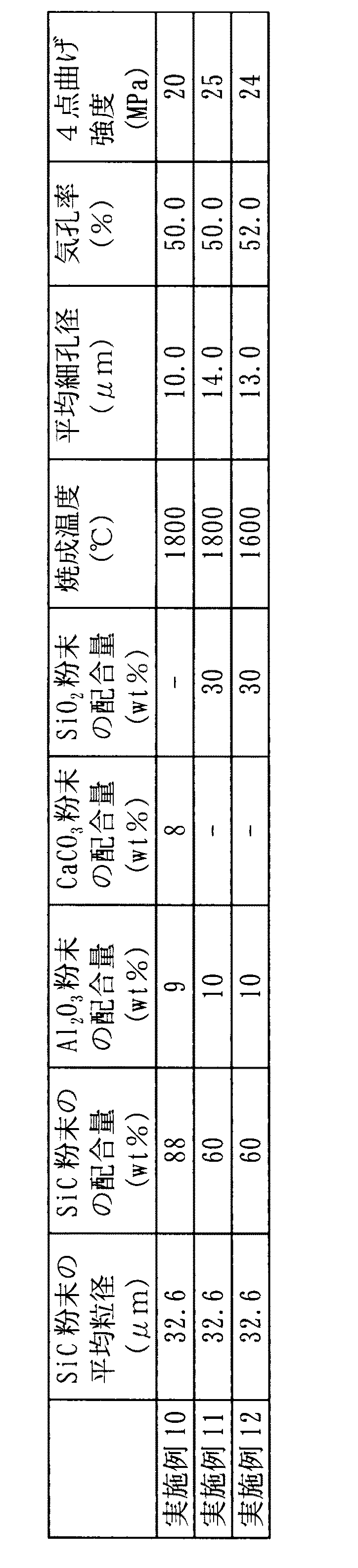
表3に示すような平均粒径を有するSiC原料粉末、平均粒径0.5μmのAl2O3粉末、平均粒径0.5μmのCaCO3粉末、平均粒径4μmのSiO2粉末を、同表に示す組成となるように配合し、この粉末100重量部に対して、有機バインダーとしてメチルセルロース6重量部、界面活性剤2.5重量部、及び水24重量部を加え、均一に混合及び混練して成形用の坏土を得た。得られた坏土を前記実施例1〜7と同様にしてハニカム形状に成形し、酸化雰囲気において550℃で3時間、脱脂のための仮焼を行った後、N2雰囲気において表3に示す焼成温度にて2時間の焼成を行い、多孔質でハニカム構造の炭化珪素焼結体を作製した。これらの焼結体について、前記実施例1〜7と同様に平均細孔径、気孔率、及び4点曲げ強度を測定し、その結果を表3に示した。また、X線回折にて結晶相を同定したところ、実施例10ではAlNが、実施例11ではSi3N4とAlNが、実施例12ではSiAlONが、それぞれSiC以外に同定された。
【0052】
【表3】
【発明の効果】
以上説明したように、本発明のハニカム構造体は、炭化珪素粒子等の耐火性粒子を含みながらも、その製造時において比較的低い焼成温度で焼結させることができるので、製造コストを抑えるとともに歩留も向上し、安価に提供することができる。また、多孔質のハニカム構造体であるので、自動車排ガス浄化用のフィルターや触媒担体等として高SV条件下でも好適に使用できる。[0001]
BACKGROUND OF THE INVENTION
The present invention relates to a honeycomb structure used for an automobile exhaust gas purification filter, a catalyst carrier and the like.
[0002]
[Prior art]
Porous honeycomb structure as a filter for collecting and removing particulate matter contained in dust-containing fluids such as diesel engine exhaust gas, or as a catalyst carrier for supporting catalyst components for purifying harmful substances in exhaust gas The body is widely used. It is also known to use refractory particles such as silicon carbide (SiC) particles as a constituent material of such a honeycomb structure.
[0003]
As a specific related technique, for example, in JP-A-6-182228, a silicon carbide powder having a predetermined specific surface area and impurity content is used as a starting material, which is molded into a desired shape, dried, and 1600 to 2200. A porous silicon carbide catalyst carrier having a honeycomb structure obtained by firing in a temperature range of ° C. is disclosed.
[0004]
On the other hand, in JP-A-61-26550, a vitrification material is added to a readily oxidizable material or a refractory composition containing a readily oxidizable material, and mixed, kneaded and molded together with a binder. JP-A-8-165171 discloses a method for producing a vitrified material-containing refractory, characterized in that a molded body is barely fired in a furnace in a non-oxidizing atmosphere. Silicon carbide molded bodies formed by adding an inorganic binder based on glass, glass or lithium silicate are disclosed.
[0005]
Japanese Patent Laid-Open No. 6-182228 discloses a conventional method for producing a porous silicon carbide sintered body by adding a binder such as glassy flux or clay to silicon carbide particles as an aggregate. After that, a method is also introduced in which the molded body is baked and solidified at a temperature at which the binder melts.
[0006]
Furthermore, Japanese Examined Patent Publication Nos. 61-13845 and 61-13846 disclose silica sand, ceramic pulverized materials, metal oxides such as Al 2 O 3 , TiO 2 , ZrO 2 , silicon carbide, nitrides and borides. Alternatively, a high-temperature ceramic filter in which refractory particles sized to a predetermined particle size made of other refractory materials are formed into a porous bottomed cylindrical body with a refractory binder such as water glass, frit, glaze, etc. The preferred refractory particle average diameter, refractory particle size distribution, tubular body porosity, tubular body average pore diameter, tubular body pore volume, tubular body partition wall thickness, and the like are disclosed.
[0007]
Furthermore, Japanese Patent Laid-Open Nos. 10-29866, 2-6371, and 61-97165 describe the production of silicon carbide bricks bonded with sialon which is an oxynitride of Si and Al. Methods, compositions, etc. are disclosed.
[0008]
[Problems to be solved by the invention]
In the sintered form (necking) by recrystallization reaction of silicon carbide powder itself disclosed in JP-A-6-182228, the silicon carbide component evaporates from the surface of the silicon carbide particles, and this is a contact portion (neck portion) between the particles. ), The neck portion grows and a bonded state is obtained. However, in order to evaporate silicon carbide, a very high firing temperature is required, which leads to high costs and a coefficient of thermal expansion. Since a high material has to be fired at a high temperature, there is a problem that the firing yield is lowered.
[0009]
On the other hand, the method of bonding raw material silicon carbide powder with vitreous as disclosed in JP-A-61-26550 and JP-A-6-182228 requires a low firing temperature of 1000 to 1400 ° C. At this time, since the binder was once melted, it was very difficult to obtain a porous body.
[0010]
Further, although the filters shown in Japanese Patent Publication Nos. 61-13845 and 61-13848 are porous, they have a thick bottomed cylindrical body with a partition wall of 5 to 20 mm. Such high SV (space velocity) conditions were not applicable.
[0011]
Furthermore, silicon carbide bricks bonded with sialon as disclosed in JP-A-10-29866, JP-A-2-6371, and JP-A-61-97165 are all furnace linings, shelves, etc. The porosity is as small as 20% or less, and considering pressure loss, it is completely unsuitable for applications such as automobile exhaust gas purification filters.
[0012]
The present invention has been made in view of such conventional circumstances, and can be manufactured inexpensively at a relatively low firing temperature while containing refractory particles such as silicon carbide particles, and is sufficiently porous and highly An object of the present invention is to provide a honeycomb structure having a specific surface area, which can be suitably used under a high SV condition as a filter for purifying an automobile exhaust gas by a process such as plugging or as a catalyst carrier, and a method for producing the honeycomb structure.
[0013]
[Means for Solving the Problems]
According to the present invention, a honeycomb structure having a large number of through holes penetrating in the axial direction partitioned by partition walls, the group consisting of refractory particles as an aggregate, rare earth, alkaline earth, Al and Si There is provided a honeycomb structure including one or more selected elements and having a crystal containing one or more of these elements and being porous.
[0014]
Moreover, according to the present invention, one or more raw materials containing one or more elements selected from the group consisting of rare earth, alkaline earth, Al and Si and an organic binder are added to the refractory particle raw material. A kneaded material obtained by mixing and kneading is formed into a honeycomb shape, the obtained molded body is calcined to remove the organic binder in the molded body, and then fired. A manufacturing method is provided.
[0015]
DETAILED DESCRIPTION OF THE INVENTION
The honeycomb structure of the present invention uses a mechanism called dissolution precipitation, whereas the manufacturing method described in, for example, the above-mentioned JP-A-6-182228 uses a mechanism called evaporation condensation in a sintering mechanism. Thus, the refractory particles are bonded together. In this dissolution and precipitation mechanism, an appropriate sintering aid is selected, added to the refractory particles as an aggregate, mixed, and fired, and then the auxiliaries react with the refractory particles. The surface dissolves to form a liquid phase. The dissolved component moves to the neck portion having a low energy state in the liquid phase and precipitates while containing the added auxiliary component, and the substance moved to the neck portion bonds the particles together.
[0016]
In the case where the liquid phase is produced by the reaction of the auxiliaries and the refractory particles, the auxiliaries first react with each other during the firing process to form a liquid phase and react with the refractory particles. There is also. However, in general, since the liquid phase is more easily wetted by the refractory particles and the reaction becomes easier, it is preferable to select a combination in which the auxiliaries have a eutectic point lower than the firing temperature. Specifically, one or more elements selected from the group consisting of rare earths (Y, La, Ce, Yb, etc.), alkaline earths (Mg, Ca, Sr, Ba, etc.), Al and Si are used as auxiliary agents. One or more types of raw materials (hereinafter referred to as “raw materials containing rare earths”) are used. Of these elements, Si is particularly effective in lowering the melting point of the auxiliary agent.
[0017]
One or more elements selected from the group consisting of rare earth, alkalinity, Al and Si contained in the honeycomb structure of the present invention are thus included in the raw material added as an auxiliary during the production. It is contained in the crystal mainly precipitated at the neck portion and exists in the structure. Furthermore, a raw material containing B and / or C as an element for promoting mass transfer on the particle surface, for example, B 4 C which is a compound of these, may be added to the refractory particles. The body will also contain B and / or C.
[0018]
Further, the honeycomb structure of the present invention has a crystal containing one or more of the above-mentioned elements contained in the raw material added as an auxiliary agent, which means that the crystal is precipitated from the liquid phase. . As described above, since the liquid phase is used for bonding the refractory particles to be aggregates, if crystals do not precipitate from the liquid phase, it will remain as a glass in the fired body, but the glass has a neck portion. When the main phase is reached, the strength, corrosion resistance, and heat resistance at the neck portion of the refractory particles become insufficient, and the characteristics of the honeycomb structure itself deteriorate. For this reason, crystals must be precipitated from the liquid phase.
[0019]
As described above, the honeycomb structure of the present invention does not evaporate the refractory particles themselves as in the recrystallization method, but binds the refractory particles by utilizing the reaction and the liquid phase generated by the reaction. Therefore, a very high temperature is not required at the time of firing, and the manufacturing cost can be reduced and the yield can be improved. Further, the present invention can be applied to thick-walled bottomed cylindrical bodies as disclosed in Japanese Patent Publication Nos. 61-13845 and 61-13846, and Japanese Patent Laid-Open Nos. 10-29866 and 2-6371. Since the porous honeycomb structure is not a brick as disclosed in Japanese Patent Laid-Open No. 61-97165, it can be used under high SV conditions as a filter or catalyst carrier for automobile exhaust gas purification.
[0020]
It is preferable that the honeycomb structure of the present invention has a structure in which refractory particles are bonded together by crystals in a state where the shape of the raw material particles is retained. Moreover, when the honeycomb structure of the present invention is used as a filter for collecting and removing particulate matter contained in the dust-containing fluid, the porosity is preferably in the range of 30 to 90%. When the porosity of the honeycomb structure is less than 30%, the filtration rate is insufficient, and when it exceeds 90%, the strength as the structure is insufficient. Furthermore, when used in applications where pressure loss is a concern, such as automobile exhaust gas purification filters, the porosity is preferably 40% or more.
[0021]
Similarly, when the honeycomb structure of the present invention is used as a filter, the average pore diameter of the honeycomb structure is preferably determined according to the object to be filtered. For example, when used as a diesel particulate filter (DPF) for collecting and removing particulates contained in exhaust gas discharged from a diesel engine, the average pore diameter is preferably in the range of 2 to 50 μm. . If the average pore diameter is less than 2 μm, the pressure loss is remarkably increased even when a small amount of particulates are deposited. Conversely, if the average pore diameter exceeds 50 μm, the particulates are easily removed.
[0022]
The thickness of the partition walls that partition the flow holes (cells) of the honeycomb structure is preferably 4 mil or more (102 μm or more). If the partition wall thickness is less than 4 mil (102 μm), it is difficult to maintain sufficient strength as a structure. Further, the strength is closely related to the porosity, and in the case of the honeycomb structure of the present invention, if the partition wall thickness is set so that the partition wall thickness and the porosity satisfy the following relationship, the required strength can be obtained. Obtained and found to be preferred.
[Expression 4]
Partition thickness (μm) ≥ Porosity (%) x 4
[0023]
Furthermore, if the partition wall thickness is set so that the partition wall thickness and the porosity satisfy the following relationship, sufficient strength can be obtained, which is more preferable.
[Equation 5]
Partition thickness (μm) ≥ Porosity (%) x 5
[0024]
On the other hand, when used as a filter such as DPF, the partition wall thickness is preferably 50 mil or less (1270 μm or less). This is because if the partition wall thickness exceeds 50 mil (1270 μm), there is a concern about insufficient filtration speed or increased pressure loss. This also has a close relationship with the porosity, and the problem can be avoided by setting the partition wall thickness so that the partition wall thickness and the porosity satisfy the following relationship.
[Formula 6]
Partition thickness (μm) ≦ Porosity (%) × 20
[0025]
The cell density of the honeycomb structure is preferably in the range of 5 to 1000 cells / in 2 (0.7 to 155 cells / cm 2 ). When the cell density is less than 5 cells / square inch (0.7 cells / cm 2 ), the honeycomb structure has insufficient strength, and when used as a filter, the filtration area is also insufficient. On the contrary, if it exceeds 1000 cells / in 2 (155 cells / cm 2 ), the pressure loss is increased, which is not preferable.
[0026]
Next, the manufacturing method of the honeycomb structure of the present invention will be described. In manufacturing the honeycomb structure of the present invention, first, a rare earth-containing raw material and an organic binder are added to a refractory particle raw material and mixed and kneaded to obtain a molding clay.
[0027]
The kind of the refractory particles to be used is not particularly limited, but Al 2 O 3 , ZrO 2 , Y 2 O 3 in the oxide system, SiC in the carbide system, Si 3 N 4 , AlN, other mullite in the nitride system, etc. For example, SiC or the like has high heat resistance and is preferably used for applications such as DPF that is frequently exposed to high temperatures when the accumulated particulates are subjected to combustion treatment.
[0028]
The average particle diameter of the refractory particle material is preferably 2 to 4 times the average pore diameter of the honeycomb structure (sintered body) finally obtained by this production method. Since the honeycomb structure obtained by this manufacturing method has a relatively low firing temperature, the particle shape and particle size of the refractory particle raw material are generally maintained until after firing. Therefore, when the ratio is less than 2 times, the particle size is too small with respect to the desired pore size, and as a result, the small refractory particles are elongated and bonded to form large pores. Thus, it is difficult to obtain such a high strength that can maintain a thin wall structure such as a honeycomb structure.
[0029]
In addition, for example, when the refractory particles are SiC particles, recrystallized SiC that has been applied to a porous honeycomb structure in the past requires an aggregate raw material particle size almost equal to the desired pore size from its reaction mechanism. On the other hand, the SiC particles bonded by the precipitated crystals as in the honeycomb structure of the present invention may have a particle size larger than twice the pore size. Compared with SiC, it is possible to use a raw material which is coarse, that is, inexpensive, and has a large cost merit.
[0030]
On the contrary, when the ratio exceeds 4 times, the particle diameter of the refractory particles used for the desired pore diameter is too large, and even when the refractory particles are densely packed at the molding stage, In addition, it is difficult to obtain desired pores, and it is also not preferable in terms of reducing the porosity for filter applications.
[0031]
Raw materials containing rare earths react with refractory particles during firing, or react with each other to form a liquid phase, which clings to refractory particles and plays a role in joining particles together. The amount added is closely related to the surface area of the refractory particles. The surface area of the refractory particles in this case is the reason why the liquid phase covers and adheres to the refractory particles, and thus depends on the shape of the particles. It is more appropriate to use the geometric surface area S = 4πr 2 (r is the average particle diameter of the refractory particles) in which the refractory particles are regarded as spheres rather than the surface area. When this geometric surface area S = 4πr 2 is used, “the amount W of the raw material containing rare earth per unit surface area of the refractory particles” can be simply calculated by the following equation.
[Expression 7]
W = {(4 / 3πr 3 × ρ) / (weight ratio of refractory particles)} × {(weight ratio of raw material containing rare earth) / (4πr 2 )}
(Where r is the average particle size of the refractory particles and ρ is the specific gravity of the refractory particles.)
[0032]
In the production method of the present invention, the amount of the rare earth-containing raw material added is preferably set so that the “amount W of the rare earth-containing raw material per unit surface area of the refractory particles” is 3 to 30 g / m 2 . Is less than 3 g / m 2, binder is insufficient, thin wall it is difficult to obtain a strength capable of maintaining the structure such as a honeycomb structure, it exceeds 30 g / m 2 Conversely, suitably refractory particles Since the liquid phase is generated more than can be bonded to each other, the strength is improved, but adverse effects such as a decrease in porosity and a reduction in average pore diameter are caused.
[0033]
The average particle size of the raw material containing rare earth is preferably 50% or less of the average particle size of the refractory particles as the aggregate. Rare earth-containing raw materials generate a liquid phase by firing and move so as to cling to the refractory particles while gathering. The space occupied by the particles remains as large voids, resulting in a decrease in strength or a decrease in filter efficiency (filtering leakage) when used as a filter.
[0034]
In general, when extruding the honeycomb structure, it is possible to extrude more smoothly by mixing two or more raw material powders having a certain degree of particle size difference. It is preferable to make it 30% or less of the average particle diameter of the refractory particles as the aggregate. As a raw material form of a raw material containing rare earth or the like, an oxide is usually used, but inorganic salts such as nitrates and chlorides, nitrides, metals, and the like can be used if necessary. In addition, the use of a compound containing two or more kinds of necessary elements, such as clay mineral, is advantageous in terms of cost and productivity improvement by improving moldability.
[0035]
In order to smoothly extrude a clay made of refractory particles as an aggregate and containing a rare earth-containing raw material and, if necessary, a pore-forming agent into a honeycomb shape, one or more organic substances are used as a molding aid. It is preferable to add 2% by weight or more of the binder out of the total amount of the main raw materials (fire-resistant particle raw materials and rare earth-containing raw materials). However, addition exceeding 30% by weight is not preferable because it causes excessive high porosity after calcination and leads to insufficient strength.
[0036]
Furthermore, when extruding into a honeycomb structure having a partition wall thickness of 20 mil (508 μm) or less, it is preferable to add an organic binder in the range of 4 to 20% by weight. If the addition amount is less than 4% by weight, it is difficult to extrude into such a thin wall. Conversely, if it exceeds 20% by weight, it is difficult to maintain the shape after extrusion.
[0037]
When the honeycomb structure is used as a filter, a pore-forming agent may be added at the time of preparing the clay for the purpose of increasing the porosity. The amount of pore-forming agent added is preferably 30% by weight or less based on the total amount of the main raw materials (fire-resistant particle raw materials and rare earth-containing raw materials). When the amount added exceeds 30% by weight, the porosity becomes excessively high, resulting in insufficient strength. Since pores are formed in the trace of the pore-forming agent after burning, the average particle size is preferably in the range of 25 to 100% with respect to the average pore size to be obtained after firing. Examples of the pore-forming agent to be used include graphite, wheat flour, starch, phenol resin, polymethyl methacrylate, polyethylene, polyethylene terephthalate and the like. A pore former may be used individually by 1 type according to the objective, and may be used in combination of 2 or more type.
[0038]
Further, in the production method of the present invention, it is necessary to precipitate crystals from the liquid phase as described above. In order to promote this crystallization, a tetravalent or higher element as a nucleating agent is added to the refractory particle raw material. (Zr, Ta, Ti, P, etc.) may be added. Furthermore, a raw material containing B and / or C, which is an element that promotes mass transfer on the particle surface, may be added to the refractory particle raw material.
[0039]
A clay obtained by mixing and kneading the raw materials by a conventional method is formed into a desired honeycomb shape by an extrusion method or the like. Next, the obtained molded body is calcined to remove (degrease) the organic binder contained in the molded body, and then subjected to main firing. The calcination is preferably performed at a temperature lower than the temperature at which the raw material containing a rare earth or the like melts. Specifically, it may be temporarily held at a predetermined temperature of about 150 to 700 ° C., or may be calcined at a temperature rising rate of 50 ° C./hr or less in a predetermined temperature range.
[0040]
Regarding the method of holding at a predetermined temperature, depending on the type and amount of the organic binder used, it may be held at only one temperature level or at multiple temperature levels, and when held at multiple temperature levels, they will be held together. The time may be the same or different. Similarly, the method of slowing the rate of temperature rise may be slowed only in one temperature zone or slowed down in a plurality of sections. Further, in the case of a plurality of sections, the speeds may be different even if they are the same. Also good.
[0041]
The calcination atmosphere may be an oxidizing atmosphere, but if the molded body contains a large amount of organic binder, during the calcination, they may violently burn with oxygen and rapidly increase the temperature of the molded body. Therefore, it is also a preferable technique to suppress the abnormal temperature rise of the molded body by performing in an inert atmosphere such as N 2 or Ar. This suppression of abnormal temperature rise is an important control when a raw material having a large thermal expansion coefficient (weak to thermal shock) is used. For example, when the organic binder is added in an amount of 20% by weight (external) or more with respect to the main raw material, it is preferably calcined in the inert atmosphere.
[0042]
The calcination and the subsequent main calcination may be performed as separate processes in the same or separate furnace, or may be performed as a continuous process in the same furnace. When the calcination and the main calcination are carried out in different atmospheres, the former method is also preferable, but the latter method is also preferable from the viewpoint of the total calcination time, furnace operating cost, and the like.
[0043]
Although the temperature of this baking changes with raw materials, such as rare earths to be used, it is preferable to implement normally in the range of 1500-2000 degreeC. In practice the temperature is below 1500 ° C. of the sintering is not firmly bonded to each other refractory particles for the liquid phase is not sufficiently generated, conversely, when it exceeds 2000 ° C., the viscosity of the dissolved components is too low firing This is not preferable because a bias such as concentration in the vicinity of the body surface or the lower part of the fired body occurs. In this main firing, for the purpose of promoting crystallization, it is preferable to provide an annealing step for crystallization that is held at a temperature of 1500 ° C. or lower after being held at the maximum temperature.
[0044]
Further, the atmosphere of the main firing is preferably selected according to the type of the refractory particles. For example, when the refractory particles have oxidation resistance, firing in an oxidizing atmosphere is possible, but SiC and the like can be used. Carbide particles, nitride particles typified by Si 3 N 4 , AlN, etc., which are likely to be oxidized at high temperatures, N 2 , Ar, etc. at least in the temperature range above the temperature at which oxidation starts The non-oxidizing atmosphere is preferable. In the case of firing in an N 2 atmosphere, the crystal phase of the binder may be nitride or oxynitride, which may provide better characteristics than strength and thermal conductivity when the crystal phase is an oxide. Therefore, it is also preferable to use different firing atmospheres according to the purpose.
[0045]
【Example】
EXAMPLES Hereinafter, although this invention is demonstrated further in detail based on an Example, this invention is not limited to these Examples.
[0046]
(Examples 1-7)
SiC raw material powder having an average particle size as shown in Table 1, Y 2 O 3 powder having an average particle size of 2 μm, Al 2 O 3 powder having an average particle size of 0.5 μm, Mg powder having an average particle size of 3 μm, average particle size 4 μm of SiO 2 powder and B 4 C powder were blended so as to have the composition shown in the table, and 6 parts by weight of methyl cellulose as an organic binder and 2.5 parts by weight of a surfactant with respect to 100 parts by weight of the powder. And 24 parts by weight of water were added and mixed and kneaded uniformly to obtain a clay for molding. The obtained clay was formed into a honeycomb shape with an outer diameter of 45 mm, a length of 120 mm, a partition wall thickness of 0.43 mm, and a cell density of 100 cm / square inch (16 cells / cm 2 ) by an extrusion molding machine. This honeycomb formed body was calcined for degreasing at 550 ° C. for 3 hours in an oxidizing atmosphere, and then fired at a firing temperature shown in Table 1 for 2 hours in an Ar atmosphere to carbonize the porous honeycomb structure. A silicon sintered body was produced. For these sintered bodies, the average pore diameter and the porosity were measured with a mercury porosimeter, and the 4-point bending strength was further measured. The results are shown in Table 1. Further, when the crystal phase was identified by X-ray diffraction, it was confirmed that the crystal phase was composed of a single phase or a compound of oxide added as SiC and an auxiliary agent.
[0047]
[Table 1]
(Example 8)
A silicon carbide sintered body having a honeycomb structure was prepared in the same manner as in Example 4 except that 1% by weight of ZrO 2 powder was additionally added to the powder blended to have the composition of Example 4 shown in Table 1. Produced. For this sintered body, the average pore diameter, porosity, and 4-point bending strength were measured in the same manner as in Examples 1 to 7, and the results are shown in Table 2. Moreover, when observed by X-ray diffraction, the halo which shows presence of a glass phase compared with Example 4 was reducing.
[0049]
Example 9
A honeycomb structured silicon carbide sintered body was manufactured in the same manner as in Example 4 except that an annealing step was performed in which firing was held at a maximum temperature (1800 ° C.) and then held at 1400 ° C. for 3 hours. . For this sintered body, the average pore diameter, porosity, and 4-point bending strength were measured in the same manner as in Examples 1 to 7, and the results are shown in Table 2. Moreover, when observed by X-ray diffraction, the halo which shows presence of a glass phase compared with Example 4 was reducing.
[0050]
[Table 2]
(Examples 10 to 12)
SiC raw material powder having an average particle size as shown in Table 3, Al 2 O 3 powder having an average particle size of 0.5 μm, CaCO 3 powder having an average particle size of 0.5 μm, and SiO 2 powder having an average particle size of 4 μm are the same. It mix | blends so that it may become a composition shown to a table | surface, 6 weight part of methylcellulose, 2.5 weight part of surfactant, and 24 weight part of water are added as an organic binder with respect to 100 weight part of this powder, and it mixes and knead | mixes uniformly. Thus, a clay for molding was obtained. The obtained clay was formed into a honeycomb shape in the same manner as in Examples 1 to 7, and calcined for degreasing at 550 ° C. for 3 hours in an oxidizing atmosphere, and then shown in Table 3 in an N 2 atmosphere. Firing was carried out at a firing temperature for 2 hours to produce a porous silicon carbide sintered body having a honeycomb structure. About these sintered compacts, the average pore diameter, the porosity, and the 4-point bending strength were measured in the same manner as in Examples 1 to 7, and the results are shown in Table 3. When the crystal phase was identified by X-ray diffraction, AlN was identified in Example 10, Si 3 N 4 and AlN were identified in Example 11, and SiAlON was identified in Example 12 other than SiC.
[0052]
[Table 3]
【The invention's effect】
As described above, the honeycomb structure of the present invention can be sintered at a relatively low firing temperature at the time of manufacture while containing fireproof particles such as silicon carbide particles, thereby reducing the manufacturing cost. Yield is improved and can be provided at low cost. Moreover, since it is a porous honeycomb structure, it can be suitably used under high SV conditions as a filter or catalyst carrier for purifying automobile exhaust gas.
Claims (10)
Priority Applications (7)
| Application Number | Priority Date | Filing Date | Title |
|---|---|---|---|
| JP2001027370A JP4464568B2 (en) | 2001-02-02 | 2001-02-02 | Honeycomb structure and manufacturing method thereof |
| EP02716416A EP1364930B1 (en) | 2001-02-02 | 2002-01-28 | Honeycomb structure and method for preparation thereof |
| US10/240,322 US6764742B2 (en) | 2001-02-02 | 2002-01-28 | Honeycomb structure body and production method thereof |
| PL02356708A PL356708A1 (en) | 2001-02-02 | 2002-01-28 | Honeycomb shaped body and its production method |
| PCT/JP2002/000604 WO2002062726A1 (en) | 2001-02-02 | 2002-01-28 | Honeycomb structure and method for preparation thereof |
| DE60235798T DE60235798D1 (en) | 2001-02-02 | 2002-01-28 | WAVY STRUCTURE AND METHOD OF MANUFACTURING THE SAME |
| ZA200208006A ZA200208006B (en) | 2001-02-02 | 2002-10-04 | Honeycomb structure and method for preparation thereof. |
Applications Claiming Priority (1)
| Application Number | Priority Date | Filing Date | Title |
|---|---|---|---|
| JP2001027370A JP4464568B2 (en) | 2001-02-02 | 2001-02-02 | Honeycomb structure and manufacturing method thereof |
Publications (2)
| Publication Number | Publication Date |
|---|---|
| JP2002234779A JP2002234779A (en) | 2002-08-23 |
| JP4464568B2 true JP4464568B2 (en) | 2010-05-19 |
Family
ID=18892032
Family Applications (1)
| Application Number | Title | Priority Date | Filing Date |
|---|---|---|---|
| JP2001027370A Expired - Lifetime JP4464568B2 (en) | 2001-02-02 | 2001-02-02 | Honeycomb structure and manufacturing method thereof |
Country Status (7)
| Country | Link |
|---|---|
| US (1) | US6764742B2 (en) |
| EP (1) | EP1364930B1 (en) |
| JP (1) | JP4464568B2 (en) |
| DE (1) | DE60235798D1 (en) |
| PL (1) | PL356708A1 (en) |
| WO (1) | WO2002062726A1 (en) |
| ZA (1) | ZA200208006B (en) |
Cited By (1)
| Publication number | Priority date | Publication date | Assignee | Title |
|---|---|---|---|---|
| EP2860165A2 (en) | 2013-09-27 | 2015-04-15 | NGK Insulators, Ltd. | Porous material, manufacturing method of the same, and honeycomb structure |
Families Citing this family (32)
| Publication number | Priority date | Publication date | Assignee | Title |
|---|---|---|---|---|
| JP4266103B2 (en) * | 2001-12-07 | 2009-05-20 | 日本碍子株式会社 | Method for producing porous ceramic body |
| JP3927038B2 (en) * | 2001-12-21 | 2007-06-06 | 日本碍子株式会社 | Si-containing honeycomb structure and manufacturing method thereof |
| DE60320966D1 (en) | 2002-03-29 | 2008-06-26 | Ngk Insulators Ltd | SILICON CARBIDE-BASED POROUS MATERIAL AND METHOD OF MANUFACTURING THEREOF |
| JP4404538B2 (en) * | 2002-10-18 | 2010-01-27 | 日本碍子株式会社 | Silicon carbide catalyst body for exhaust gas purification and method for producing the same |
| ATE481151T1 (en) * | 2003-02-28 | 2010-10-15 | Ibiden Co Ltd | CERAMIC HONEYCOMB STRUCTURE |
| ZA200508293B (en) * | 2003-04-24 | 2007-10-31 | Dow Global Technologies Inc | Improved porous mullite bodies and methods of forming them |
| PL1640351T3 (en) * | 2003-05-29 | 2013-09-30 | Ngk Insulators Ltd | Method for producing honeycomb structure |
| US7488366B2 (en) * | 2003-07-25 | 2009-02-10 | Ngk Insulators, Ltd. | Ceramic porous body and method for evaluating its permeability |
| US7381680B2 (en) * | 2004-04-21 | 2008-06-03 | Dow Global Technologies Inc. | Method for increasing the strength of porous ceramic bodies and bodies made therefrom |
| JP4796496B2 (en) * | 2004-06-25 | 2011-10-19 | イビデン株式会社 | Filter, manufacturing method thereof, and exhaust purification device |
| EP1652831A4 (en) * | 2004-06-25 | 2009-07-01 | Ibiden Co Ltd | Process for producing porous body, porous body, and honeycomb structural body |
| EP1787968B1 (en) | 2004-09-30 | 2012-12-12 | Ibiden Co., Ltd. | Method for manufacturing porous article, porous article and honeycomb structure |
| CN100386150C (en) * | 2005-08-17 | 2008-05-07 | 云南菲尔特环保科技有限公司 | Ceramic catalyst carrier, particle trap and particle trapping device and preparation method thereof |
| US7485594B2 (en) * | 2005-10-03 | 2009-02-03 | Dow Global Technologies, Inc. | Porous mullite bodies and methods of forming them |
| US20070105707A1 (en) * | 2005-11-10 | 2007-05-10 | Ngk Insulators, Ltd. | Method for manufacturing honeycomb structure |
| WO2007055033A1 (en) * | 2005-11-14 | 2007-05-18 | Ibiden Co., Ltd. | Filter, exhaust gas purifying apparatus for internal combustion engine and exhaust gas purifying method |
| JP4900663B2 (en) * | 2006-03-08 | 2012-03-21 | 独立行政法人産業技術総合研究所 | Exhaust gas purification filter and manufacturing method thereof |
| WO2008032391A1 (en) * | 2006-09-14 | 2008-03-20 | Ibiden Co., Ltd. | Process for producing honeycomb structure and raw-material composition for burnt honeycomb |
| JP4599344B2 (en) * | 2006-12-25 | 2010-12-15 | 株式会社ノリタケカンパニーリミテド | Method for producing non-oxide porous ceramic material |
| FR2916366B1 (en) * | 2007-05-23 | 2009-11-27 | Saint Gobain Ct Recherches | TEXTURE PARTICLE FILTER FOR CATALYTIC APPLICATIONS |
| US8709577B2 (en) * | 2007-06-28 | 2014-04-29 | Corning Incorporated | High porosity ceramic honeycomb article containing rare earth oxide and method of manufacturing same |
| WO2009069731A1 (en) * | 2007-11-30 | 2009-06-04 | Ngk Insulators, Ltd. | Silicon carbide porous body |
| WO2009141876A1 (en) * | 2008-05-20 | 2009-11-26 | イビデン株式会社 | Honeycomb structure |
| FR2931366B1 (en) * | 2008-05-22 | 2011-01-21 | Saint Gobain Ct Recherches | SIC-VITROCERAMIC COMPOSITE FILTER |
| US20090298670A1 (en) * | 2008-05-27 | 2009-12-03 | Martin Joseph Murtagh | Method for removing graphite from cordierite bodies |
| MX2010014553A (en) * | 2008-06-27 | 2011-02-15 | Dow Global Technologies Inc | Method for making porous acicular mullite bodies. |
| JP5053981B2 (en) * | 2008-10-30 | 2012-10-24 | 日本碍子株式会社 | Silicon carbide based porous material and method for producing the same |
| JP4920752B2 (en) * | 2010-01-05 | 2012-04-18 | 日本碍子株式会社 | Honeycomb structure |
| JP5926593B2 (en) | 2012-03-28 | 2016-05-25 | 日本碍子株式会社 | Porous material, method for producing the same, and honeycomb structure |
| JP5747127B2 (en) | 2012-06-15 | 2015-07-08 | 株式会社ノリタケカンパニーリミテド | Alumina porous body and method for producing the same |
| JP6824909B2 (en) * | 2015-06-02 | 2021-02-03 | サイエンティフィック・デザイン・カンパニー・インコーポレーテッドScientific Design Company Incorporated | Porous body with improved pore structure |
| US10676401B2 (en) * | 2018-04-23 | 2020-06-09 | Scientific Design Company, Inc. | Porous bodies with enhanced pore architecture prepared with oxalic acid |
Family Cites Families (29)
| Publication number | Priority date | Publication date | Assignee | Title |
|---|---|---|---|---|
| JPS55137022A (en) | 1979-04-14 | 1980-10-25 | Ngk Insulators Ltd | High temperature use ceramic filter |
| JPS55137021A (en) | 1979-04-14 | 1980-10-25 | Ngk Insulators Ltd | High temperature-use ceramic filter |
| JPS5891071A (en) | 1981-11-27 | 1983-05-30 | 旭硝子株式会社 | Manufacture of sintered body |
| JPS6126550A (en) | 1984-07-13 | 1986-02-05 | 株式会社 広築 | Manufacture of refractories containing gllasified material |
| JPS6191076A (en) | 1984-10-12 | 1986-05-09 | イビデン株式会社 | Porous silicon carbide sintered body and manufacture |
| JPS6197165A (en) | 1984-10-17 | 1986-05-15 | 東京高級炉材株式会社 | Beta' sialon bonding silicon carbide material and manufacture |
| JPH026371A (en) | 1988-06-24 | 1990-01-10 | Kawasaki Steel Corp | Production of silicon carbide brick having sialon linkage |
| US4946487A (en) * | 1988-11-14 | 1990-08-07 | Norton Company | High temperature filter |
| JPH0722666B2 (en) * | 1990-03-02 | 1995-03-15 | 日本碍子株式会社 | Filter material for molten aluminum |
| JPH0813706B2 (en) * | 1991-07-02 | 1996-02-14 | 工業技術院長 | Silicon carbide / metal silicon composite and method for producing the same |
| JP3213850B2 (en) * | 1992-01-08 | 2001-10-02 | イビデン株式会社 | Method for producing sintered silicon carbide porous body |
| JPH05306614A (en) * | 1992-04-28 | 1993-11-19 | Matsushita Electric Ind Co Ltd | Exhaust gas filter and manufacturing method thereof |
| JPH06107476A (en) | 1992-09-24 | 1994-04-19 | Tokai Carbon Co Ltd | Microwave regenerable SiC porous body for exhaust gas purification |
| JP3548914B2 (en) | 1992-12-16 | 2004-08-04 | イビデン株式会社 | Method for producing catalyst carrier |
| JPH07215777A (en) | 1994-02-07 | 1995-08-15 | Isuzu Ceramics Kenkyusho:Kk | Porous ceramics and method for manufacturing the same |
| JP3288536B2 (en) * | 1994-06-21 | 2002-06-04 | 日本碍子株式会社 | Exhaust gas filter and exhaust gas treatment device using the same |
| JPH0812462A (en) | 1994-06-22 | 1996-01-16 | Denki Kagaku Kogyo Kk | Electroconductive ceramic, its production and use |
| JPH08165171A (en) | 1994-12-07 | 1996-06-25 | Nippon Cement Co Ltd | Silicon carbide molded form and sintered compact therefrom |
| JP3461615B2 (en) | 1995-04-12 | 2003-10-27 | 電気化学工業株式会社 | Honeycomb structure and manufacturing method thereof |
| JPH09202671A (en) * | 1996-01-25 | 1997-08-05 | Ibiden Co Ltd | Production of silicon carbide-based honeycomb filter |
| JPH09268085A (en) | 1996-03-30 | 1997-10-14 | Asahi Glass Co Ltd | Method for producing porous silicon carbide body |
| DE19727115C2 (en) | 1996-07-01 | 2001-08-02 | Fraunhofer Ges Forschung | Porous silicon carbide ceramics and process for their production |
| JP3927261B2 (en) | 1996-07-17 | 2007-06-06 | 黒崎播磨株式会社 | Manufacturing method of sialon bond SiC brick |
| JP3928673B2 (en) * | 1997-09-17 | 2007-06-13 | 旭硝子エンジニアリング株式会社 | Cordierite ceramic sintered body, composition therefor and production method therefor |
| JPH11253722A (en) * | 1998-03-11 | 1999-09-21 | Ngk Insulators Ltd | Ceramic filter |
| FR2796638B1 (en) * | 1999-07-21 | 2001-09-14 | Ceramiques Tech Et Ind S A | HONEYCOMB MONOLITH STRUCTURE IN POROUS CERAMIC MATERIAL, AND USE AS A PARTICLE FILTER |
| JP4455708B2 (en) * | 2000-01-17 | 2010-04-21 | 日本碍子株式会社 | Honeycomb structure and manufacturing method thereof |
| JP4136319B2 (en) | 2000-04-14 | 2008-08-20 | 日本碍子株式会社 | Honeycomb structure and manufacturing method thereof |
| JP4426083B2 (en) * | 2000-11-17 | 2010-03-03 | 日本碍子株式会社 | Silicon carbide based porous material and method for producing the same |
-
2001
- 2001-02-02 JP JP2001027370A patent/JP4464568B2/en not_active Expired - Lifetime
-
2002
- 2002-01-28 US US10/240,322 patent/US6764742B2/en not_active Expired - Lifetime
- 2002-01-28 EP EP02716416A patent/EP1364930B1/en not_active Expired - Lifetime
- 2002-01-28 PL PL02356708A patent/PL356708A1/en not_active Application Discontinuation
- 2002-01-28 WO PCT/JP2002/000604 patent/WO2002062726A1/en not_active Ceased
- 2002-01-28 DE DE60235798T patent/DE60235798D1/en not_active Expired - Lifetime
- 2002-10-04 ZA ZA200208006A patent/ZA200208006B/en unknown
Cited By (2)
| Publication number | Priority date | Publication date | Assignee | Title |
|---|---|---|---|---|
| EP2860165A2 (en) | 2013-09-27 | 2015-04-15 | NGK Insulators, Ltd. | Porous material, manufacturing method of the same, and honeycomb structure |
| US9259721B2 (en) | 2013-09-27 | 2016-02-16 | Ngk Insulators, Ltd | Porous material, manufacturing method of the same, and honeycomb structure |
Also Published As
| Publication number | Publication date |
|---|---|
| EP1364930B1 (en) | 2010-03-31 |
| US20030108458A1 (en) | 2003-06-12 |
| PL356708A1 (en) | 2004-06-28 |
| JP2002234779A (en) | 2002-08-23 |
| EP1364930A4 (en) | 2006-02-22 |
| ZA200208006B (en) | 2003-10-06 |
| EP1364930A1 (en) | 2003-11-26 |
| US6764742B2 (en) | 2004-07-20 |
| DE60235798D1 (en) | 2010-05-12 |
| WO2002062726A1 (en) | 2002-08-15 |
Similar Documents
| Publication | Publication Date | Title |
|---|---|---|
| JP4464568B2 (en) | Honeycomb structure and manufacturing method thereof | |
| JP4455708B2 (en) | Honeycomb structure and manufacturing method thereof | |
| JP4136319B2 (en) | Honeycomb structure and manufacturing method thereof | |
| JP4426083B2 (en) | Silicon carbide based porous material and method for producing the same | |
| JP5478259B2 (en) | Silicon carbide based porous material | |
| US6815038B2 (en) | Honeycomb structure | |
| US6746748B2 (en) | Honeycomb structure and process for production thereof | |
| JP2002356383A (en) | Silicon carbide based porous compact and method for manufacturing the same |
Legal Events
| Date | Code | Title | Description |
|---|---|---|---|
| A621 | Written request for application examination |
Free format text: JAPANESE INTERMEDIATE CODE: A621 Effective date: 20060825 |
|
| A131 | Notification of reasons for refusal |
Free format text: JAPANESE INTERMEDIATE CODE: A131 Effective date: 20090818 |
|
| A521 | Request for written amendment filed |
Free format text: JAPANESE INTERMEDIATE CODE: A523 Effective date: 20091014 |
|
| A131 | Notification of reasons for refusal |
Free format text: JAPANESE INTERMEDIATE CODE: A131 Effective date: 20091208 |
|
| A521 | Request for written amendment filed |
Free format text: JAPANESE INTERMEDIATE CODE: A523 Effective date: 20100126 |
|
| TRDD | Decision of grant or rejection written | ||
| A01 | Written decision to grant a patent or to grant a registration (utility model) |
Free format text: JAPANESE INTERMEDIATE CODE: A01 Effective date: 20100216 |
|
| A01 | Written decision to grant a patent or to grant a registration (utility model) |
Free format text: JAPANESE INTERMEDIATE CODE: A01 |
|
| A61 | First payment of annual fees (during grant procedure) |
Free format text: JAPANESE INTERMEDIATE CODE: A61 Effective date: 20100219 |
|
| FPAY | Renewal fee payment (event date is renewal date of database) |
Free format text: PAYMENT UNTIL: 20130226 Year of fee payment: 3 |
|
| R150 | Certificate of patent or registration of utility model |
Ref document number: 4464568 Country of ref document: JP Free format text: JAPANESE INTERMEDIATE CODE: R150 Free format text: JAPANESE INTERMEDIATE CODE: R150 |
|
| FPAY | Renewal fee payment (event date is renewal date of database) |
Free format text: PAYMENT UNTIL: 20130226 Year of fee payment: 3 |
|
| EXPY | Cancellation because of completion of term |