JP4388918B2 - Imaging device - Google Patents
Imaging device Download PDFInfo
- Publication number
- JP4388918B2 JP4388918B2 JP2005240179A JP2005240179A JP4388918B2 JP 4388918 B2 JP4388918 B2 JP 4388918B2 JP 2005240179 A JP2005240179 A JP 2005240179A JP 2005240179 A JP2005240179 A JP 2005240179A JP 4388918 B2 JP4388918 B2 JP 4388918B2
- Authority
- JP
- Japan
- Prior art keywords
- reason
- deletion
- shooting
- gain
- result
- Prior art date
- Legal status (The legal status is an assumption and is not a legal conclusion. Google has not performed a legal analysis and makes no representation as to the accuracy of the status listed.)
- Expired - Fee Related
Links
Images


Landscapes
- Studio Devices (AREA)
Description
本発明は撮像装置、特にデジタルカメラ等の撮像装置の調整に関する。 The present invention relates to adjustment of an image pickup apparatus, particularly an image pickup apparatus such as a digital camera.
デジタルカメラ等の撮像装置においては、ホワイトバランス調整や露出補正等、ユーザが所望の撮影結果を得ることができるように各種のパラメータを調整する機能が付加されている。 In an imaging apparatus such as a digital camera, a function for adjusting various parameters such as white balance adjustment and exposure correction so that the user can obtain a desired shooting result is added.
しかしながら、近年は特にコンパクト化及び高機能化が進み、一部のユーザ以外ではデジタルカメラの有する機能を理解し、かつ、撮影状況に応じてこれらの機能を正しく使い分けることが一層困難となっている。 However, in recent years, in particular, compactness and high functionality have progressed, and it has become more difficult for non-some users to understand the functions of digital cameras and to properly use these functions according to the shooting situation. .
下記の特許文献1には、モニタ表示装置を第1の表示部と第2の表示部に区分し、第1の表示部に所定のメニュー表示を行うとともに、その関連項目を第2の表示部に表示してカメラ操作を容易化する技術が記載されている。
In
しかしながら、デジタルカメラの有する機能をメニュー表示するだけでは、結局、当該機能についての知識が要求されることとなる。例えば、「スローシンクロ」なるメニューが表示されても、このスローシンクロなる機能がどのようなもので、どのような撮影状況下で使用すればいいのか知らなければ意味が無い。一般のユーザにとっては、現在のデジタルカメラの設定条件において撮影された画像を視認し、その結果に対して特定の不満を持つ場合にデジタルカメラの設定を変更したいと欲することが多く、このような場合にデジタルカメラの機能について専門的な知識を有していなくても、直感的な操作により機能を使いこなせることが望ましい。 However, if only the functions of the digital camera are displayed on the menu, the knowledge about the functions is required. For example, even if a menu “slow sync” is displayed, it is meaningless if the function of this slow sync is not known and under what shooting conditions it should be used. For general users, they often want to change the settings of the digital camera when they are visually dissatisfied with the result of viewing the image taken under the current digital camera setting conditions. In some cases, it is desirable to be able to make full use of the functions through intuitive operations, even if they do not have specialized knowledge about the functions of the digital camera.
本発明の目的は、ユーザの直感的な操作により、すなわち、得られた撮影結果を視認し、その撮影結果に対して特定の不満の理由を有する場合にその直感的な理由を入力することにより各種機能を自動設定ないし自動調整し、これにより所望の画像を極めて容易に得ることができる撮像装置を提供することにある。 It is an object of the present invention to intuitively operate a user, that is, to visually recognize the obtained photographing result and to input the intuitive reason when there is a specific reason for dissatisfaction with the photographing result. It is an object of the present invention to provide an imaging apparatus capable of automatically setting or automatically adjusting various functions and thereby obtaining a desired image very easily.
本発明は、被写体に対してストロボ光を照射するストロボ手段と、被写体からの光を光電変換して画像信号として出力する撮像手段と、前記撮像手段に入射する入射光量を調整する光量調整手段と、前記撮像手段から出力された画像信号のゲインを調整するゲイン調整手段と、ゲイン調整された画像信号のホワイトバランスを調整するホワイトバランス調整手段と、ゲイン調整された前記画像信号に対してガンマ補正するガンマ補正手段と、前記ホワイトバランス調整及びガンマ補正された画像信号を撮影直後にその撮影結果として表示する表示手段とを有する撮像装置であって、撮影直後の前記撮影結果の削除指示を入力する削除スイッチと、撮影直後の前記撮影結果の削除理由を選択入力する削除理由スイッチと、入力された削除理由に応じ、前記ストロボ手段、前記ゲイン調整手段、前記光量調整手段、ホワイトバランス調整手段及びガンマ補正手段の動作を統合制御する制御手段とを有する。
The present invention includes a strobe unit that irradiates a subject with strobe light, an imaging unit that photoelectrically converts light from the subject and outputs the image signal, and a light amount adjusting unit that adjusts an incident light amount incident on the imaging unit. A gain adjusting unit that adjusts the gain of the image signal output from the imaging unit; a white balance adjusting unit that adjusts a white balance of the gain-adjusted image signal; and a gamma correction for the gain-adjusted image signal. gamma correction means for, an imaging device having a display means for displaying as a shooting result immediately after shooting an image signal the is white balance adjustment and gamma correction and inputs a deletion instruction of the photographing result immediately after shooting and delete switch, wherein the deletion reason switch a deletion reason of imaging results to select input immediately after shooting, the deletion reason entered Flip with the strobe means, the gain adjusting means, said light amount adjusting means, and control means for controlling integrating operation of the white balance adjustment unit and the gamma correction means.
本発明では撮影結果を表示し、この撮影結果を視認したユーザが撮影結果に満足せずに削除したいと欲する場合にその削除理由を入力する。制御手段は、選択入力された削除理由に応じて撮像装置内のストロボ手段や光量調整手段等を制御し、ストロボの発光量や露光量を調整する。本発明では、ユーザはストロボ手段や光量調整手段を意識する必要がなく、単に直感的な削除理由を選択入力すれば足りる。 In the present invention, the photographing result is displayed, and when the user who has visually recognized the photographing result wants to delete the photographing result without being satisfied with the photographing result, the reason for the deletion is input. The control means controls the strobe means, the light amount adjusting means, etc. in the image pickup apparatus in accordance with the selection input reason for deletion, and adjusts the light emission amount and exposure amount of the strobe. In the present invention, the user does not need to be aware of the strobe means and the light amount adjustment means, and it is sufficient to simply select and input an intuitive deletion reason.
本発明の1つの実施形態では、削除理由として、撮影結果の暗さに関する理由(撮影結果が暗い等)、撮影結果の色に関する理由(撮影結果の色がおかしい等)、撮影結果の輪郭のぼやけに関する理由、撮影結果の人物顔部の輝度に関する情報(顔部が影あるいは白飛び等)、撮影結果の背景の輝度に関する理由(背景が暗い等)、撮影結果の空の色に関する理由(晴天にも拘わらず空が白っぽい)等が入力される。制御手段は、これらの削除理由に応じてストロボ手段の発光量や光量調整手段の露光量を増減調整する。 In one embodiment of the present invention, the reason for deletion is the reason for the darkness of the shooting result (such as the shooting result is dark), the reason for the color of the shooting result (such as the color of the shooting result is strange), and the blurring of the contour of the shooting result. Information on the brightness of the person's face as a result of photographing (such as shadows or whiteout in the face), reason about the brightness of the background of the photographed result (such as a dark background), reason about the sky color of the photographed result (clear weather) However, the sky is whitish). The control unit adjusts the light emission amount of the strobe unit and the exposure amount of the light amount adjustment unit in accordance with these reasons for deletion.
本発明によれば、ユーザは直感的な削除理由を入力するだけで所望の撮影結果を得ることができる。また、ユーザは削除理由を選択入力するだけでストロボ手段や光量調整手段等を調整することができるので、結果として、撮像装置の有する機能について正確な知識を有していなくてもこれらの機能を有効利用することができる。 According to the present invention, the user can obtain a desired photographing result only by inputting an intuitive deletion reason. In addition, since the user can adjust the strobe unit, the light amount adjusting unit, and the like only by selecting and inputting the reason for deletion, as a result, even if the user does not have accurate knowledge about the functions of the imaging apparatus, these functions can be performed. It can be used effectively.
以下、図面に基づき本発明の実施形態について、デジタルカメラを例にとり説明する。 Hereinafter, embodiments of the present invention will be described with reference to the drawings, taking a digital camera as an example.
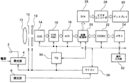
図1には、本実施形態に係るデジタルカメラの全体構成ブロック図が示されている。レンズ10は、被写体からの光を集光する。絞り(アパーチャ)12及びシャッタ13は、それぞれ被写体からの入射光量及び入射時間を調整する。機械式のシャッタ13を有さず、後述するタイミングジェネレータTG34からの駆動信号に基づいてCCD14の電荷蓄積時間を制御することで入射時間を調整することもできる(電子シャッタ)。機械式シャッタ13と電子シャッタをともに備えてもよい。レンズ10、絞り12及びシャッタ13で集光され光量調整された光は、撮像素子としてのCCD14に入射する。CCD14は、入射した光をその光量に応じた電気信号(電圧信号)に変換して出力する。撮像素子としては、CCD14の代わりにCMOSを用いてもよい。CCD14は、光電変換して得られた電気信号をCDS/AGC16に出力する。CDS(相関2重サンプリング)/AGC(オートゲインコントロール)16は、CCD14からの電気信号をサンプリングし、また、その信号レベル(ゲイン)を調整してA/D18に出力する。A/D18は、CDS/AGC16からのアナログ信号をデジタル信号に変換して画像処理部20に出力する。画像処理部20は、システムLSIで構成され、入力デジタル信号に所定の信号処理を施してコーデックCODEC22あるいはD/A26に出力する。
FIG. 1 is a block diagram showing the overall configuration of a digital camera according to this embodiment. The
以下、画像処理部20について説明する。
Hereinafter, the
図2には、画像処理部20の機能ブロック図が示されている。画像処理部20は、A/D18からのデジタル信号(デジタル画像信号)に対し、ホワイトバランス補正、ガンマ(γ)補正、及び色信号・輝度信号分離の各処理を順次実行する。
FIG. 2 shows a functional block diagram of the
ホワイトバランス補正処理部20aは、A/D18からのデジタル画像信号に対し、CCD14に設けられたカラーフィルタの各フィルタ感度の相違等に基づいて各色のバランスを補正し、補正した画像信号をガンマ補正処理部20bに出力する。ガンマ補正処理部20bは、ホワイトバランス補正された画像信号に対してガンマ補正、すなわち入力値に対して出力値を指数関数的に変換することで表示デバイスの特性に合致させ線形性を確保する。ガンマ補正は、具体的には入力値と出力値との関係をマップとしてメモリに記憶しておき、このマップにアクセスすることで入力値に対応する出力値を得ることで実行される。マップで規定されていない中間値は、その近傍の値(両端の値)を用いて補間する。マップではなく、ガンマ補正関数をメモリに記憶しておき、この補正関数を用いて変換してもよい。ガンマ補正処理部20bは、ガンマ補正したデジタル画像信号をRGB信号生成処理部20cに出力する。RGB信号生成処理部20cは、デジタル画像信号に対し、ノイズ除去処理や帯域制限処理、高域信号補正処理等を施してR信号、G信号、B信号の各信号を生成し、輝度信号生成処理部20d及び色差信号生成処理部20eに出力する。輝度信号生成処理部20dは、RGB信号生成処理部20cからのRBG信号を所定の合成比で合成することで輝度信号(Y信号)を生成する。また、色差信号生成処理部20eも同様にRGB信号生成処理部20cからのRGB信号を所定の合成比で合成することで色差信号(Cb、Cr)を生成する。これらの輝度信号や色差信号は、上記のようにCODEC22あるいはD/A26に供給される。
The white balance
再び図1に戻り、コーデックCODEC22は、画像処理部20からの画像信号を圧縮、符号化してメモリ24に記憶し、あるいはメモリ24から読み出された符号化画像データを解凍・復号して画像処理部20に供給する。メモリ24は、例えばフラッシュメモリで構成され、コーデックCODEC22により圧縮符号化された画像データ、例えばJPEGフォーマットやTIFFフォーマットで圧縮符号化された画像データを記憶する。D/A26は、画像処理部20からの画像信号をアナログ画像信号に変換してビデオエンコーダ28に出力する。ビデオエンコーダ28は、アナログ画像信号をディスプレイ30に適合する形式の映像信号(NTSC信号等)にエンコードしてディスプレイ30に出力する。ディスプレイ30は、液晶パネルや有機ELパネル等で構成され、ビデオエンコーダ28からの画像信号を表示する。ディスプレイ30は、デジタルカメラのファインダあるいは画像モニタとして機能する。
Returning to FIG. 1 again, the
操作入力部32は、デジタルカメラのユーザがシャッタ操作や被写体あるいはシーンの選択等の各種コマンドあるいはメニューを指定するための操作スイッチであり、その操作に応じた各種コマンド信号をバスを介してマイコン36あるいは画像処理部20に出力する。タイミングジェネレータTG34は、CCD14、CDS/AGC16、A/D18及び画像処理部20の動作タイミングを制御する。タイミングジェネレータTGの制御により、一定のフレームレートで画像信号が画像処理部20の内蔵メモリ(図示せず)に記憶されていく。内蔵メモリに記憶された画像信号は、間引き処理により画像サイズが所定サイズに縮小され、D/A26及びビデオエンコーダ28を介してファインダとしてのディスプレイ30に表示される。操作入力部32の一つであるシャッタボタンがユーザにより操作されると、タイミングジェネレータTG34はシャッタボタンが押下された時点の画像信号を取り込むように画像処理部20を制御し、画像処理部20の内蔵メモリに記憶された当該タイミングの画像信号をコーデックCODEC22により圧縮符号化してメモリ24に記憶する。あるいは、シャッタが押下された時点の画像信号は、画像処理部20の内蔵メモリから読み出されてD/A26、ビデオエンコーダ28を介してファインダあるいは液晶モニタとしてのディスプレイ30に表示される。ユーザは、この画面を見ることで撮影結果を視認し評価する。
The
ストロボ2は、デジタルカメラに内蔵され、発光部4により発光の有無及び発光量が調整される。発光部4は、マイコン36からの制御信号により駆動される。発光部4は、後述するように主コンデンサを備え、主コンデンサに蓄積された電荷によりキセノン管等のストロボ2を発光させる。発光部4は、ストロボ発光時には、基本的にプリ発光と本発光を実行する。すなわち、プリ発光時の発光量と被写体からの反射光から本発光時の発光量を設定し、設定された発光量で本発光を実行する。被写体からの反射光は測光部6で検出されマイコン36に供給される。
The
マイコン(マイクロコンピュータ)36は、絞り12、シャッタ13、CDS/AGC16のAGC機能、タイミングジェネレータTG34、画像処理部20及び発光部4を統括的に制御する。すなわち、操作入力部32から入力されたシャッタ操作信号や各種コマンド信号、メニュー選択信号等に基づいて絞り12やシャッタ13、電子シャッタ、AGC16の発光量を調整して露光量を調整するとともに、メモリ24への画像データの書き込みと読み出し、ディスプレイ30への表示を制御する。また、マイコン36は、ユーザによる操作入力部32の操作を促すため、あるいは操作補助のため、所定の各種操作メニューや現在の状態(撮影可能枚数やシャッタ速度、絞り値、設定モード、ヒストグラム等)をディスプレイ30に表示する。また、マイコン36は、発光部4内の主コンデンサの端子電圧を監視してその充放電を制御することでストロボ2のプリ発光及び本発光、並びにそれぞれの発光量を制御する。従来、測光により被写体が暗く、ストロボ2を発光させる必要があると判定した場合、マイコン36は常にプリ発光及び本発光を実行しているが、本実施形態では、操作入力部32から入力されたユーザの要求に応じ、必要に応じてプリ発光を無効化する。プリ発光を無効化するのは、プリ発光による主コンデンサの端子電圧低下を防ぎ、発光時の発光量をその分だけ余分に増大させるためである。すなわち、マイコン36は、絞り12、シャッタ13、CDS/AGC16のAGCゲイン及びストロボ2のプリ発光、本発光を統合制御することで、ユーザ所望の撮影結果を生成する。
The microcomputer (microcomputer) 36 comprehensively controls the
発光部4は、主コンデンサ、放電回路、充電回路及び切替スイッチを有する。充電回路には電源回路からの電源ラインが接続される。マイコン36は、ストロボ2を発光しないタイミングにおいて切替スイッチを充電回路側に切り替えて主コンデンサを充電する。主コンデンサの端子電圧は直列接続された2つの抵抗の分圧信号としてマイコン36に供給され、これによりマイコン36は主コンデンサの端子電圧を監視する。また、マイコン36は、ストロボ2を発光させる必要が生じた場合、切替スイッチを放電回路側に切り替えて主コンデンサに蓄積された電荷を放電してストロボ2に供給する。ストロボ2の発光には、プリ発光と本発光があり、それぞれの発光量は端子電圧及び放電時間で調整される。具体的には、マイコン36は、主コンデンサの端子電圧、被写体輝度情報(プリ発光前の輝度情報)、及び被写体距離情報に基づいてプリ発光の発光量を算出する。一般に、端子電圧が大きいほどプリ発光の発光量が増大するが、端子電圧が一定値以上であればプリ発光量を端子電圧によらずに一定値に設定してもよい。また、マイコン36は、プリ発光時の発光量(積算発光量)と被写体からの反射光量に基づいて本発光の発光量を算出する。プリ発光時の発光量から自然光下における反射光量の差分を演算してプリ発光時の発光量のみを抽出し、適正露光量と比較して不足する分の露光量を本発光時の発光量とする。
The light emitting unit 4 includes a main capacitor, a discharge circuit, a charging circuit, and a changeover switch. A power supply line from the power supply circuit is connected to the charging circuit. The
図3には、図1における操作入力部32の構成が示されている。操作入力部32は、デジタルカメラとして通常有する機能である、電源スイッチやレリーズボタン(シャッタボタン)、メニュー選択スイッチ、撮影画像読出選択スイッチ等の他、削除スイッチ32a及び削除理由選択スイッチ32bを備える。削除スイッチ32aは、ディスプレイ30に表示された撮影結果を視認したユーザが、何らかの理由により撮影結果に満足しないために当該撮影結果を削除する(メモリからの削除)ときに操作する。また、削除理由スイッチ32bは、ユーザが削除スイッチ32aを操作したときに、さらに当該撮影結果を削除する理由を選択入力するためのスイッチである。ユーザが削除スイッチ32aを操作すると、削除コマンドがマイコン36に供給される、マイコン36は、この削除コマンドに応じ、その削除理由を判別するために、ディスプレイ30に複数の削除理由をリスト表示する。ユーザは、削除理由選択スイッチ32bを用いてこのリストの中から削除理由を選択入力する。ユーザが削除理由選択スイッチ32bを操作して削除理由を選択入力すると、それぞれの削除理由のコマンドがマイコン36に供給される。マイコン36は、選択入力された削除理由に応じて、絞り12、シャッタ13、CDS/AGC16のゲイン、及び発光部4を統合的に制御する。ユーザから見れば、デジタルカメラの有する各種調整機能についての正確な知識を有さなくても、撮影結果に対する直感的な不満足を直感的な「削除理由」の形式で入力するだけで、デジタルカメラ側で自動的に各種の調整を行うことになる。
FIG. 3 shows the configuration of the
図4には、ユーザが削除スイッチ32aを操作した場合に、ディスプレイ30に表示される削除理由リストの一例が示されている。削除理由としては、「とにかく消したい」、「暗い」、「色がおかしい」、「赤目」、「ブレた」、「顔が影」、「顔が白飛び」、「背景が真っ黒」、「空が青く写らない」、「オークションに不適当」が表示される。
FIG. 4 shows an example of a deletion reason list displayed on the
「とにかく消したい」は、撮影結果の構図等にそもそも不満足であるため削除する場合に選択するメニューである。「暗い」は、撮影結果が全体として暗く、本来もっと明るい画像を期待している場合に選択するメニューである。「色がおかしい」は、撮影結果の色が意図した色と異なる場合に選択するメニューである。「赤目」は、撮影結果の人物等の眼部が赤い場合に選択するメニューである。「ブレた」は、撮影結果の輪郭がぼんやりしている場合に選択するメニューである。「顔が影」は、撮影結果の顔部が影となっている場合に選択するメニューである。「顔が白飛び」は、撮影結果の顔部が逆に白く飛んでいる場合に選択するメニューである。「背景が真っ黒」は、撮影結果の人物等は問題ないが背景が暗いあるいは真っ黒の場合に選択するメニューである。「空が青く写らない」は、撮影結果の空部が晴天にも拘わらず青く写っていない場合に選択するメニューである。「オークションに不適当」は、撮影結果を特定の用途(この場合にはインターネットを用いたオークションに出品するための撮影)に用いる場合であって見栄えが悪いときに選択するメニューである。 “I want to delete it anyway” is a menu to be selected when deleting because the composition of the photographing result is unsatisfactory in the first place. “Dark” is a menu that is selected when the shooting result is dark overall and a brighter image is expected. “Color is wrong” is a menu to be selected when the color of the photographing result is different from the intended color. “Red-eye” is a menu that is selected when the eyes of a photographed person or the like are red. “Blurred” is a menu that is selected when the outline of the photographing result is blurred. “Face is shadow” is a menu to be selected when the face portion of the photographing result is a shadow. “Face is white” is a menu to be selected when the face portion of the photographed result is white. “Background is black” is a menu that is selected when the photographed person or the like has no problem but the background is dark or black. “The sky does not appear blue” is a menu that is selected when the sky part of the photographing result is not blue even though the sky is clear. “Unsuitable for auction” is a menu that is selected when the photographing result is used for a specific purpose (in this case, photographing for listing in an auction using the Internet) and looks bad.
これらのメニューは、いずれもユーザが撮影結果から直感的に理解できるメニューである。マイコン36は、これらのメニューのいずれが選択入力されたかを判別し、それぞれのメニューに応じて絞り12やシャッタ13、発光装置4等を所定の制御プログラムに従って制御する。
These menus are all menus that the user can intuitively understand from the photographing result. The
以下、選択入力された削除理由に応じたマイコン36の制御について説明する。なお、制御プログラムはファームウェアとしてマイコン36のROMに記憶しておく。
Hereinafter, the control of the
図5及び図6には、マイコン36の制御フローチャートが示されている。AEモードでユーザが所望の被写体を撮影すると、画像処理部20は当該撮影結果をディスプレイ30に表示する(S101)。表示時間は一定時間でよく、撮影結果の詳細を視認できるように、ユーザからの操作に応じて画像の特定部位を拡大して表示してもよい。撮影結果をデジタルカメラの背面モニタに表示する技術は周知である。
5 and 6 show control flowcharts of the
撮影結果を表示した後、マイコン36はユーザからの削除コマンドの入力待機状態となる(S102)。この状態でユーザが削除スイッチ32aを操作すると、マイコン36は削除コマンドに応じて画像処理部20に指令し、予め設定された削除理由リストをディスプレイ30に表示してユーザの削除理由入力を促す(S103)。ユーザが削除理由を入力すると、マイコン36はどの削除理由が入力されたか判別する。
After displaying the photographing result, the
選択入力された削除理由が「とにかく消したい」である場合(S104)、マイコン36はユーザからの削除要求に応じてディスプレイ30に表示されている撮影結果をメモリ24から削除する(S105)。このとき、マイコン36は削除以外の特定の調整処理を実行しない。従って、次にレリーズボタンが押下された場合には、基本的に前回と同一の条件で撮影される。
If the selected deletion reason is “I want to delete it anyway” (S104), the
選択入力された削除理由が「暗い」である場合(S106)、マイコン36はユーザからの削除要求に応じてディスプレイ30に表示されている撮影結果をメモリ24から削除する(S107)。また、マイコン36は、削除理由「暗い」に応じ、この要求を満たすために露光量の増大が必要であるとして絞り12、シャッタ13、発光部4、AGC16のゲインを調整する(S108)。具体的には、前回の撮影時にストロボ2を発光させているか否かを判定し(ストロボ発光の有無はマイコン36の内蔵メモリに記憶させておく)、ストロボ2を発光させていない場合、つまり自然光が十分存在する場合にはシャッタ13のシャッタ速度を遅くして露光量を増大させる。一方、ストロボ2を発光させている場合、発光部4に指令してストロボの発光量を増大させる。上記のように、ストロボ2はプリ発光と本発光を行い、発光部4はプリ発光の結果に応じて本発光の発光量Qを設定しているが、発光部4はマイコン36からの指令に応じ、本発光の発光量を所定量ΔQだけ増大させてQ+ΔQとする。なお、前回の撮影時に既に本発光の発光量をΔQだけ増大させている場合には、マイコン36は、プリ発光を無効として本発光のみを実行させる。プリ発光及び本発光を行うと、プリ発光により主コンデンサの端子電圧が低下し、本発光時の最大可能発光量が減少してしまう。そこで、プリ発光を行わず本発光のみとして本発光の発光量を最大化するのである。マイコン36は、ストロボ2のプリ発光を無効化するとともに、AGC16のゲインを所定量だけ増大させてISO感度を上げてもよい。
If the selected deletion reason is “dark” (S106), the
選択入力された削除理由が「色がおかしい」である場合(S109)、マイコン36は
さらにディスプレイ30に照明条件をリスト表示してユーザに照明条件の選択入力を促す(S110)。照明条件リストは、例えば「日向」、「日陰」、「蛍光灯」、「タングステン」、「知らない」等である。照明条件が入力されると、マイコン36はユーザからの削除要求に応じてディスプレイ30に表示されている撮影結果をメモリ24から削除する(S111)。また、マイコン36は、削除理由「色がおかしい」及び照明条件に応じ、画像処理部20のホワイトバランス補正処理部20aに指令して照明条件に合致するホワイトバランス調整を実行する(S112)。なお、照明条件として「知らない」が選択入力された場合、マイコン36はデフォルトである日向用のホワイトバランス調整を実行する。
If the selected deletion reason is “Improper Color” (S109), the
選択入力された削除理由が「赤目」である場合(S113)、マイコン36はユーザからの削除要求に応じてディスプレイ30に表示されている撮影結果をメモリ24から削除する(S114)。また、マイコン36は、削除理由「赤目」に応じ、所定の赤目低減処理を実行する(S115)。具体的には、本発光に先立ってストロボ2を数回発光させて被写体の瞳孔を収縮させ赤目を抑制する。もちろん、他の方法を用いてもよい。
If the selected deletion reason is “red-eye” (S113), the
選択入力された削除理由が「ブレた」である場合(S116)、マイコン36はユーザからの削除要求に応じてディスプレイ30に表示されている撮影結果をメモリ24から削除する(S117)。また、マイコン36は、削除理由「ブレた」に応じ、AGC16のゲインを所定量だけ増大させてISO感度を上げる(S118)。また、シャッタ速度を増大する。
If the selected deletion reason is “blurred” (S116), the
次に、図6において、選択入力された削除理由が「顔が影」である場合(S119)、マイコン36はユーザからの削除要求に応じてディスプレイ30に表示されている撮影結果をメモリ24から削除する(S120)。また、マイコン36は、削除理由「顔が影」に応じ、ストロボ2を発光させる、あるいはシャッタ13のシャッタ速度を所定量だけ遅くして露出補正(露出増大)を行う(S121)。ストロボ2を発光させるか、露出補正を行うかは自然光の光量に応じて決定する。すなわち、自然光の光量を測光センサで検出し所定光量以下であればストロボ発光で対応し、所定光量以上であれば露出補正で対応する。
Next, in FIG. 6, when the deletion reason selected and input is “face shadow” (S 119), the
選択入力された削除理由が「顔が白飛び」である場合(S122)、マイコン36はユーザからの削除要求に応じてディスプレイ30に表示されている撮影結果をメモリ24から削除する(S123)。また、マイコン36は、削除理由「顔が白飛び」に応じ、ストロボ2の発光量を低減すべく発光部4に指令する。すなわち、ストロボ2の発光量はプリ発光の結果に応じて設定されるが、プリ発光により設定された本発光の発光量Qを所定量Δqだけ低減してQ−Δqとする。なお、前回の撮影時にストロボ2を発光していない場合にはこの処理を実行しない(S124)。
If the selected deletion reason is “exposed face” (S122), the
選択入力された削除理由が「背景が真っ黒」である場合(S125)、マイコン36はユーザからの削除要求に応じてディスプレイ30に表示されている撮影結果をメモリ24から削除する(S126)。また、マイコン36は、削除理由「背景が真っ黒」に応じ、前回の撮影時にストロボ2を発光させている場合にはいわゆるスローシンクロモードに移行する。ここに、スローシンクロモードとは、ストロボ2を発光させるとともにシャッタ13のシャッタ速度を遅くして露光量を増大させる処理である。一方、前回の撮影時においてストロボ2を発光させていない場合には、AGC16のゲインを増大させてISO感度を所定量だけ増大する(S127)。
If the selected deletion reason is “black background” (S125), the
選択入力された削除理由が「空が青く写らない」である場合(S128)、マイコン36はユーザからの削除要求に応じてディスプレイ30に表示されている撮影結果をメモリ24から削除する(S129)。また、マイコン36は、削除理由「空が青く写らない」に応じ、デジタルカメラの最大反射率を増大する調整を行い(S130)、かつ、最大反射率の増大に連動させてガンマ補正値を調整後の最大反射率に対応した値に変更する(S131)。ここに、「最大反射率」とは、CCD14の最大出力に対応する入射光量の指標である。CIPA(Camera & Imaging Products Association:カメラ映像機器工業会規格)では、感度基準レベルに階調の中間レベルを採用しており、具体的にはガンマ補正後のデジタル最大出力値(8ビットの場合には255)を被写体反射率100%に対応させた時の18%標準ニュートラルグレイ被写体に対応する輝度値(Y値)を基準とする(8ビットの場合には118)。もちろん、18%グレイ被写体に対する輝度値をCIPA基準の118ではなく他の値、例えば130にすることも可能であり、人肌をどのように表現するかでこの数値が定まり得る。18%グレー被写体の輝度値を設定した場合、デジタル最大出力値に対応する反射率、すなわち最大反射率は、以下の式で定義される。
If the selected deletion reason is “the sky does not appear blue” (S128), the
最大反射率(%)=18(%)×CCD出力の最大値/適正露光条件下で撮影された
18%グレー被写体のCCD出力値
Maximum reflectance (%) = 18 (%) × maximum CCD output / taken under proper exposure conditions
CCD output value of 18% gray subject
本実施形態では、デフォルト状態では、18%グレー被写体の輝度は、ガンマ補正後で130(8bit)、最大反射率は120%に設定される。このデフォルト状態では、CCD14の出力は反射率0%〜反射率120%の間の入射光量に応じて画像信号を出力する。デフォルト状態で被写体を撮影した場合、被写体の輝度が高いために、白飛び、青飛び(空が白っぽくなる)、赤飛び(赤い色が白っぽくなる)等が生じる場合がある。また、フラットな照明条件下(スタジオ撮影の場合等)において被写体のコントラストが低くなる場合がある。これらは、撮影条件に対して0%〜120%の反射率で規定されるダイナミックレンジが適当でないため生じるので、最大反射率をデフォルトの120%より増大させる、あるいは減少させることで、撮影条件に合致したダイナミックレンジを設定することができる。但し、単に最大反射率を増減変更したのみ(ガンマ補正値は固定)では、その最大反射率の増減に応じて適正露光のターゲットである18%グレー被写体のガンマ補正後の出力値が変動してしまうため(最大反射率が増大すると18%グレーはダイナミックレンジ上において相対的に小さくなり、最大反射率が減少すると18%グレーは相対的に大きくなるためガンマ補正後の出力値も変動する)、所望の撮影結果を得ることができず、ユーザは撮影結果を別途パーソナルコンピュータ(PC)にダウンロードし、画像処理ソフトウェアを用いてトーンカーブを補正する等の付加的な処理が必要となってしまう。そこで、本実施形態では、最大反射率を増減変更するとともに、この最大反射率の増減に連動させてガンマ補正を変更することで、視覚的印象に則した撮影結果を得るようにしている。図7には、最大反射率70%、120%、170%にそれぞれ対応するガンマ値が例示されている。図中、Aはデフォルトの120%に対応するガンマ値、Bは170%のガンマ値、Cは70%のガンマ値である。
In the present embodiment, in the default state, the luminance of the 18% gray subject is set to 130 (8 bits) after gamma correction, and the maximum reflectance is set to 120%. In this default state, the output of the
再び図6に戻り、選択入力された削除理由が「オークションに不適当」である場合(S132)、マイコン36はユーザからの削除要求に応じてディスプレイ30に表示されている撮影結果をメモリ24から削除する(S133)。また、マイコン36は、削除理由「オークションに不適当」に応じ、S110と同様にディスプレイ30に照明条件リストを表示してユーザに照明条件の選択入力を促し、照明条件に応じたホワイトバランス調整を実行すべく画像処理部20のホワイトバランス補正処理部20aに指令する(S134)。もちろん、オークションに出品するための撮影は、通常、一定条件の下で撮影される(出品すべき商品を机の上において蛍光灯下において撮影される)ことが多いため、この条件に合致するようなホワイトバランス調整を実行してもよい。
Returning to FIG. 6 again, if the deletion reason selected and input is “unsuitable for auction” (S132), the
このように、本実施形態では、ユーザからの直感的な削除理由に応じて、絞り12やシャッタ13、ストロボ2の発光量、AGC16のゲイン(ISO感度)を単独で、あるいはこれらを所定の優先度で組み合わせて統合制御することによりユーザが所望する撮影結果を達成している。ユーザは、デジタルカメラの有する各種機能についての正確な知識を有することなく、デジタルカメラの各種機能を結果として効果的に使用し得る。
As described above, according to the present embodiment, depending on the reason for intuitive deletion from the user, the amount of light emitted from the
以上、本発明の実施形態について説明したが、本発明はこれに限定されるものではなく種々の変更が可能である。 As mentioned above, although embodiment of this invention was described, this invention is not limited to this, A various change is possible.
例えば、本実施形態では、選択入力された削除理由に応じてストロボ2等を調整しているが、次回の撮影時までに一定時間が経過した場合にこれらの調整をキャンセルし、調整を不実行とすることが好適である。一定時間経過した場合には、もはやこれらの調整が必要であった撮影状況下にはないと判断できるからである。具体的には、タイマーで一定時間経過したか否かを判定する他、一定時間何らの操作もない場合にスリープモードに移行する機能や電源OFFする機能がデジタルカメラに備わっている場合、これと組み合わせてスリープモードや電源OFFになったときに調整をキャンセルすればよい。
For example, in this embodiment, the
また、削除理由を表示するか否かは、ユーザが適宜設定可能とすることもできる。 Further, whether or not to display the reason for deletion can be appropriately set by the user.
また、削除理由を解消するためにマイコン36がストロボ2等を調整したか否かをディスプレイ30に表示してユーザに報知することも好適である。これにより、ユーザはデジタルカメラが現在、デフォルトの状態ではなく、削除理由を解消するための調整モードに移行していることを確実に認知することができる。当該調整モードを解除するためには、例えばユーザは電源をOFFに設定すればよい。マイコン36は、電源OFFに応じてストロボ2やシャッタ13、AGCゲイン(ISO感度)をデフォルト値に戻して制御する。
It is also preferable to notify the user by displaying on the
さらに、本実施形態では削除理由に応じた調整制御を実行しているが、調整後の撮影結果に対する再度の削除入力あるいは再度の削除理由入力に応じ、調整制御を適応的に変化させる所謂学習機能を有していてもよい。例えば、S119にて「顔が影」との削除理由が入力され、これに応じてマイコン36はストロボ発光あるいは露出補正を行うが、露出補正を行う調整後に再度ユーザが調整後の撮影結果に対して撮影結果を削除し、さらに削除理由として「顔が影」を入力した場合には次にストロボ発光で調整する。これは、「顔が影」との削除理由をユーザが2回目に入力したときには一層の露光量を要求しているものと学習し、2回目からは最初の削除理由「顔が影」とあわせて露出補正ではなくストロボ発光で調整するものである。あるいは、S128にて「空が青く写らない」との削除理由が入力され、これに応じてマイコン36は最大反射率をデフォルトの120%から150%に増大させた場合において、ユーザが調整後の撮影結果に対して再度削除理由として「空が青く写らない」を入力した場合には、当初の120%→150%の増大は当該ユーザにとって増大分が不足していたものと学習し、2回目からは最初の削除理由「空が青く写らない」に応じて120%→200%に増大する等である。
Furthermore, in the present embodiment, adjustment control according to the reason for deletion is executed, but a so-called learning function that adaptively changes the adjustment control according to a second deletion input or a second deletion reason input for the adjusted photographing result. You may have. For example, in S119, the reason for deletion of “face is shadow” is input, and in response to this, the
本実施形態では削除スイッチ32aを操作した後に削除理由を入力しているが、撮影画像を削除することなく不満理由を入力するためのリストをディスプレイ30に表示し、ユーザはこのリストから不満理由を選択入力してもよい。マイコン36は入力された不満理由に応じ、上記の各制御を実行する。さらに、本実施形態では削除スイッチ32aを操作することで撮影画像をメモリ24から削除しているが、削除スイッチ32aを操作した場合であっても撮影画像のデータ自体はメモリ24のいずれかのディレクトリに保持しておき、後にユーザの操作(例えばリカバリ操作等)により一旦削除した画像をディスプレイ30に表示して撮り直した画像と対比できるようにしてもよい。例えば削除スイッチ32aの操作により撮影画像を「ごみ箱」のディレクトリに移動し、必要に応じて「ごみ箱」のディレクトリから元のディレクトリに再移動できるようにしてもよい。すなわち、本実施形態の削除スイッチ32aの操作による削除には、撮影画像のデータを実際に消去する態様の他、後でリカバリできるように撮影画像のデータ自体はいずれかに保持しておく態様も含まれる。
In this embodiment, the reason for deletion is input after the
2 ストロボ、4 発光部、6 測光部、10 レンズ、12 絞り、13 シャッタ、14 CCD、16 CDS/AGC、18 A/D、20 画像処理部、22 コーデック(CODEC)、24 メモリ、26 D/A、28 ビデオエンコーダ、30 ディスプレイ、32 操作入力部、34 タイミングジェネレータ(TG)、36 マイコン。 2 strobe, 4 light emitting unit, 6 photometric unit, 10 lens, 12 aperture, 13 shutter, 14 CCD, 16 CDS / AGC, 18 A / D, 20 image processing unit, 22 codec (CODEC), 24 memory, 26 D / A, 28 Video encoder, 30 Display, 32 Operation input unit, 34 Timing generator (TG), 36 Microcomputer.
Claims (14)
被写体からの光を光電変換して画像信号として出力する撮像手段と、
前記撮像手段に入射する入射光量を調整する光量調整手段と、
前記撮像手段から出力された画像信号のゲインを調整するゲイン調整手段と、
ゲイン調整された画像信号のホワイトバランスを調整するホワイトバランス調整手段と、
ゲイン調整された前記画像信号に対してガンマ補正するガンマ補正手段と、
前記ホワイトバランス調整及びガンマ補正された画像信号を撮影直後にその撮影結果として表示する表示手段と、
を有する撮像装置であって、
撮影直後の前記撮影結果の削除指示を入力する削除スイッチと、
撮影直後の前記撮影結果の削除理由を選択入力する削除理由スイッチと、
入力された削除理由に応じ、前記ストロボ手段、前記ゲイン調整手段、前記光量調整手段、ホワイトバランス調整手段及びガンマ補正手段の動作を統合制御する制御手段と、
を有することを特徴とする撮像装置。 Strobe means for irradiating the subject with strobe light,
Imaging means for photoelectrically converting light from a subject and outputting it as an image signal;
A light amount adjusting means for adjusting an incident light amount incident on the imaging means;
Gain adjusting means for adjusting the gain of the image signal output from the imaging means;
White balance adjusting means for adjusting the white balance of the image signal whose gain has been adjusted;
Gamma correction means for performing gamma correction on the image signal whose gain has been adjusted ;
Display means for displaying the white balance adjusted and gamma-corrected image signal immediately after shooting as a shooting result;
An imaging device having
A deletion switch for inputting an instruction to delete the shooting result immediately after shooting;
A deletion reason switch for selecting and inputting the reason for deleting the shooting result immediately after shooting;
A control unit that integrally controls operations of the strobe unit, the gain adjustment unit, the light amount adjustment unit, the white balance adjustment unit, and the gamma correction unit according to the input deletion reason;
An imaging device comprising:
前記削除理由には撮影結果の暗さに関する理由が含まれ、
前記制御手段は、前記削除理由スイッチから撮影結果の暗さに関する理由が入力された場合に、前記光量調整手段の動作を制御して露光量を増減制御することを特徴とする撮像装置。 The apparatus of claim 1.
The reason for deletion includes the reason for the darkness of the shooting result,
The image pickup apparatus according to claim 1, wherein the control means controls the operation of the light amount adjusting means to increase / decrease the exposure amount when a reason related to the darkness of the photographing result is inputted from the deletion reason switch.
前記光量調整手段にはシャッタが含まれ、
前記制御手段は、前記シャッタのシャッタ速度を増減することで露光量を増減制御することを特徴とする撮像装置。 The apparatus of claim 2.
The light amount adjusting means includes a shutter,
The image pickup apparatus, wherein the control means controls the exposure amount by increasing or decreasing the shutter speed of the shutter.
前記削除理由には撮影結果の色に関する理由が含まれ、
前記制御手段は、前記削除理由スイッチから撮影結果の色に関する理由が入力された場合に、前記ホワイトバランス調整手段の動作を制御してホワイトバランスを変更することを特徴とする撮像装置。 The apparatus of claim 1.
The reason for deletion includes the reason for the color of the shooting result,
The image pickup apparatus according to claim 1, wherein the control means controls the operation of the white balance adjustment means to change the white balance when a reason related to the color of the photographing result is input from the deletion reason switch.
前記削除理由には撮影結果の輪郭のぼやけに関する理由が含まれ、
前記制御手段は、前記削除理由スイッチから撮影結果の輪郭のぼやけに関する理由が入力された場合に、前記ゲイン調整手段の動作を制御してゲインを増大し、前記シャッタのシャッタ速度を増大することを特徴とする撮像装置。 The apparatus of claim 1.
The reason for the deletion includes a reason for blurring of the outline of the photographing result,
The control means controls the operation of the gain adjusting means to increase the gain and increase the shutter speed of the shutter when a reason related to blurring of the contour of the photographing result is input from the deletion reason switch. An imaging device that is characterized.
前記削除理由には撮影結果の人物顔部の輝度に関する理由が含まれ、
前記制御手段は、前記削除理由スイッチから撮影結果の人物顔部の輝度に関する理由が入力された場合に、前記ストロボ手段の動作を制御してその発光量を制御することを特徴とする撮像装置。 The apparatus of claim 1.
The reason for deletion includes the reason for the brightness of the human face part of the shooting result,
The image pickup apparatus according to claim 1, wherein the control means controls the operation of the strobe means to control the amount of light emitted when a reason related to the brightness of the human face portion of the photographing result is inputted from the deletion reason switch.
前記削除理由には撮影結果の人物顔部の輝度に関する理由が含まれ、
前記制御手段は、前記削除理由スイッチから撮影結果の人物顔部の輝度に関する理由が入力された場合に、前記光量調整手段の動作を制御して露光量を増減することを特徴とする撮像装置。 The apparatus of claim 1.
The reason for deletion includes the reason for the brightness of the human face part of the shooting result,
The image pickup apparatus according to claim 1, wherein the control means controls the operation of the light amount adjusting means to increase / decrease the exposure amount when a reason related to the brightness of the human face portion of the photographing result is inputted from the deletion reason switch.
前記削除理由には撮影結果の背景の輝度に関する理由が含まれ、
前記制御手段は、前記削除理由スイッチから撮影結果の背景の輝度に関する理由が入力された場合に、前記ストロボ手段及び前記光量調整手段の動作を制御して露光量を増減することを特徴とする撮像装置。 The apparatus of claim 1.
The reason for deletion includes the reason for the brightness of the background of the shooting result,
The control means controls the operation of the strobe means and the light amount adjusting means to increase / decrease the exposure amount when a reason related to the brightness of the background of the photographing result is inputted from the deletion reason switch. apparatus.
前記削除理由には撮影結果の背景の輝度に関する理由が含まれ、
前記制御手段は、前記削除理由スイッチから撮影結果の背景の輝度に関する理由が入力された場合に、前記ゲイン調整手段の動作を制御してゲインを増減することを特徴とする撮像装置。 The apparatus of claim 1.
The reason for deletion includes the reason for the brightness of the background of the shooting result,
The image pickup apparatus according to claim 1, wherein the control means controls the operation of the gain adjusting means to increase or decrease the gain when a reason related to the brightness of the background of the photographing result is input from the deletion reason switch.
前記削除理由には撮影結果の空の色に関する理由が含まれ、
前記制御手段は、前記削除理由スイッチから撮影結果の空の色に関する理由が入力された場合に、前記光量調整手段及び前記ゲイン調整手段の少なくともいずれかを調整することでダイナミックレンジをシフトし、かつ、前記ガンマ補正手段のガンマ補正値を変更することを特徴とする撮像装置。 The apparatus of claim 1.
The reason for deletion includes the reason for the sky color of the shooting result,
The control means shifts the dynamic range by adjusting at least one of the light amount adjusting means and the gain adjusting means when a reason regarding the sky color of the photographing result is input from the deletion reason switch, and A gamma correction value of the gamma correction means is changed.
前記削除理由には撮影結果の用途への適不適に関する理由が含まれ、
前記制御手段は、前記削除理由スイッチから撮影結果の用途への適不適に関する理由が入力された場合に、前記ホワイトバランス調整手段の動作を制御してホワイトバランスを変更することを特徴とする撮像装置。 The apparatus of claim 1.
The reason for the deletion includes a reason for inappropriateness of the photographing result for use,
The control unit changes the white balance by controlling the operation of the white balance adjusting unit when a reason relating to the inappropriateness of the photographing result for use is input from the deletion reason switch. .
前記制御手段は、前記削除理由に応じた制御の後に得られた撮影結果に対し、再度同一削除理由が入力された場合に、該削除理由に応じた制御量を変更することを特徴とする撮像装置。 The device according to any one of claims 1 to 11,
The control means changes an amount of control according to the reason for deletion when the same reason for deletion is input again for a photographing result obtained after control according to the reason for deletion. apparatus.
前記撮像手段に入射する入射光量を調整する光量調整手段と、
前記撮像手段から出力された画像信号のゲインを調整するゲイン調整手段と、
ゲイン調整された画像信号のホワイトバランスを調整するホワイトバランス調整手段と、
ゲイン調整された前記画像信号に対してガンマ補正するガンマ補正手段と、
前記ホワイトバランス調整及びガンマ補正された画像信号を撮影直後にその撮影結果として表示する表示手段と、
を有する撮像装置であって、
撮影直後の前記撮影結果に対する不満の理由を入力する手段と、
入力された理由に応じ、前記光量調整手段、ゲイン調整手段、ホワイトバランス調整手段及びガンマ補正手段の少なくともいずれかの動作を制御する制御手段と、
を有することを特徴とする撮像装置。 Imaging means for photoelectrically converting light from a subject and outputting it as an image signal;
A light amount adjusting means for adjusting an incident light amount incident on the imaging means;
Gain adjusting means for adjusting the gain of the image signal output from the imaging means;
White balance adjusting means for adjusting the white balance of the image signal whose gain has been adjusted;
Gamma correction means for performing gamma correction on the image signal whose gain has been adjusted ;
Display means for displaying the white balance adjusted and gamma-corrected image signal immediately after shooting as a shooting result;
An imaging device having
Means for inputting the reason for dissatisfaction with the shooting result immediately after shooting;
Control means for controlling the operation of at least one of the light amount adjustment means, gain adjustment means, white balance adjustment means, and gamma correction means according to the input reason;
An imaging device comprising:
被写体に対してストロボ光を照射するストロボ手段
を有し、前記制御手段は前記入力された理由に応じ、前記ストロボ手段、光量調整手段、ゲイン調整手段、ホワイトバランス調整手段及びガンマ補正手段の少なくともいずれかの動作を制御することを特徴とする撮像装置。 The apparatus of claim 13, further comprising:
A flash unit that irradiates a subject with flash light, and the control unit is at least one of the flash unit, the light amount adjustment unit, the gain adjustment unit, the white balance adjustment unit, and the gamma correction unit according to the input reason. An image pickup apparatus that controls the operation of the above.
Priority Applications (1)
| Application Number | Priority Date | Filing Date | Title |
|---|---|---|---|
| JP2005240179A JP4388918B2 (en) | 2004-09-28 | 2005-08-22 | Imaging device |
Applications Claiming Priority (2)
| Application Number | Priority Date | Filing Date | Title |
|---|---|---|---|
| JP2004282511 | 2004-09-28 | ||
| JP2005240179A JP4388918B2 (en) | 2004-09-28 | 2005-08-22 | Imaging device |
Publications (2)
| Publication Number | Publication Date |
|---|---|
| JP2006129449A JP2006129449A (en) | 2006-05-18 |
| JP4388918B2 true JP4388918B2 (en) | 2009-12-24 |
Family
ID=36723586
Family Applications (1)
| Application Number | Title | Priority Date | Filing Date |
|---|---|---|---|
| JP2005240179A Expired - Fee Related JP4388918B2 (en) | 2004-09-28 | 2005-08-22 | Imaging device |
Country Status (1)
| Country | Link |
|---|---|
| JP (1) | JP4388918B2 (en) |
Families Citing this family (1)
| Publication number | Priority date | Publication date | Assignee | Title |
|---|---|---|---|---|
| JP5248928B2 (en) * | 2008-06-09 | 2013-07-31 | 富士フイルム株式会社 | Imaging control apparatus, method thereof, and program |
-
2005
- 2005-08-22 JP JP2005240179A patent/JP4388918B2/en not_active Expired - Fee Related
Also Published As
| Publication number | Publication date |
|---|---|
| JP2006129449A (en) | 2006-05-18 |
Similar Documents
| Publication | Publication Date | Title |
|---|---|---|
| JP4845832B2 (en) | Imaging apparatus and control method | |
| US8264585B2 (en) | Imaging apparatus capable of readily specifying undesirable photographing parameters form auto photographing parameters | |
| JP5007523B2 (en) | Imaging apparatus and program thereof | |
| US9681048B2 (en) | Image capturing apparatus and method for controlling the same | |
| US11838648B2 (en) | Image processing device, imaging apparatus, image processing method, and program for determining a condition for high dynamic range processing | |
| CN101019416A (en) | Imaging apparatus | |
| US10225486B2 (en) | Shooting apparatus and method for controlling shooting apparatus | |
| US8035729B2 (en) | Imaging apparatus and program thereof | |
| JP2008118383A (en) | Digital camera | |
| JP2010011153A (en) | Imaging apparatus, imaging method and program | |
| US20060239674A1 (en) | System and method for analyzing a digital image | |
| JP5316923B2 (en) | Imaging apparatus and program thereof | |
| JP2001230970A (en) | Image pickup device | |
| JP5473201B2 (en) | Imaging apparatus and control method thereof | |
| JP4388918B2 (en) | Imaging device | |
| JP2008085581A (en) | Imaging device | |
| JP2003309854A (en) | Digital camera | |
| JP2012199908A (en) | Image sensor compensation | |
| JP6024098B2 (en) | Imaging apparatus and imaging system | |
| JP2006145964A (en) | Imaging device | |
| JP4416608B2 (en) | Imaging device | |
| WO2006036921A1 (en) | Image capturing device | |
| JP7682954B2 (en) | Imaging device, control method and program thereof | |
| JP4481120B2 (en) | Imaging device | |
| JP2012129611A (en) | Imaging apparatus |
Legal Events
| Date | Code | Title | Description |
|---|---|---|---|
| A621 | Written request for application examination |
Free format text: JAPANESE INTERMEDIATE CODE: A621 Effective date: 20070802 |
|
| A977 | Report on retrieval |
Free format text: JAPANESE INTERMEDIATE CODE: A971007 Effective date: 20090520 |
|
| A131 | Notification of reasons for refusal |
Free format text: JAPANESE INTERMEDIATE CODE: A131 Effective date: 20090526 |
|
| A521 | Request for written amendment filed |
Free format text: JAPANESE INTERMEDIATE CODE: A523 Effective date: 20090817 |
|
| TRDD | Decision of grant or rejection written | ||
| A01 | Written decision to grant a patent or to grant a registration (utility model) |
Free format text: JAPANESE INTERMEDIATE CODE: A01 Effective date: 20090915 |
|
| A01 | Written decision to grant a patent or to grant a registration (utility model) |
Free format text: JAPANESE INTERMEDIATE CODE: A01 |
|
| A61 | First payment of annual fees (during grant procedure) |
Free format text: JAPANESE INTERMEDIATE CODE: A61 Effective date: 20091005 |
|
| R150 | Certificate of patent or registration of utility model |
Free format text: JAPANESE INTERMEDIATE CODE: R150 |
|
| FPAY | Renewal fee payment (event date is renewal date of database) |
Free format text: PAYMENT UNTIL: 20121009 Year of fee payment: 3 |
|
| FPAY | Renewal fee payment (event date is renewal date of database) |
Free format text: PAYMENT UNTIL: 20121009 Year of fee payment: 3 |
|
| FPAY | Renewal fee payment (event date is renewal date of database) |
Free format text: PAYMENT UNTIL: 20131009 Year of fee payment: 4 |
|
| S111 | Request for change of ownership or part of ownership |
Free format text: JAPANESE INTERMEDIATE CODE: R313113 |
|
| R371 | Transfer withdrawn |
Free format text: JAPANESE INTERMEDIATE CODE: R371 |
|
| S111 | Request for change of ownership or part of ownership |
Free format text: JAPANESE INTERMEDIATE CODE: R313113 |
|
| R350 | Written notification of registration of transfer |
Free format text: JAPANESE INTERMEDIATE CODE: R350 |
|
| R250 | Receipt of annual fees |
Free format text: JAPANESE INTERMEDIATE CODE: R250 |
|
| R250 | Receipt of annual fees |
Free format text: JAPANESE INTERMEDIATE CODE: R250 |
|
| R250 | Receipt of annual fees |
Free format text: JAPANESE INTERMEDIATE CODE: R250 |
|
| R250 | Receipt of annual fees |
Free format text: JAPANESE INTERMEDIATE CODE: R250 |
|
| LAPS | Cancellation because of no payment of annual fees |