JP4384816B2 - Improved fast superposition algorithm with reduced complexity and increased flexibility - Google Patents
Improved fast superposition algorithm with reduced complexity and increased flexibility Download PDFInfo
- Publication number
- JP4384816B2 JP4384816B2 JP2000573035A JP2000573035A JP4384816B2 JP 4384816 B2 JP4384816 B2 JP 4384816B2 JP 2000573035 A JP2000573035 A JP 2000573035A JP 2000573035 A JP2000573035 A JP 2000573035A JP 4384816 B2 JP4384816 B2 JP 4384816B2
- Authority
- JP
- Japan
- Prior art keywords
- frequency components
- frequency
- idft
- folding
- dft
- Prior art date
- Legal status (The legal status is an assumption and is not a legal conclusion. Google has not performed a legal analysis and makes no representation as to the accuracy of the status listed.)
- Expired - Fee Related
Links
- 238000000034 method Methods 0.000 claims description 48
- 230000008569 process Effects 0.000 claims description 41
- 238000012545 processing Methods 0.000 claims description 13
- 230000004044 response Effects 0.000 description 8
- 238000001914 filtration Methods 0.000 description 5
- 238000006243 chemical reaction Methods 0.000 description 4
- 238000011161 development Methods 0.000 description 4
- 238000005070 sampling Methods 0.000 description 4
- 238000004891 communication Methods 0.000 description 3
- 230000009467 reduction Effects 0.000 description 3
- 238000004364 calculation method Methods 0.000 description 2
- 238000000605 extraction Methods 0.000 description 2
- 230000014759 maintenance of location Effects 0.000 description 2
- 238000004519 manufacturing process Methods 0.000 description 2
- 230000005540 biological transmission Effects 0.000 description 1
- 230000015572 biosynthetic process Effects 0.000 description 1
- 230000001413 cellular effect Effects 0.000 description 1
- 230000008859 change Effects 0.000 description 1
- 230000006835 compression Effects 0.000 description 1
- 238000007906 compression Methods 0.000 description 1
- 230000007423 decrease Effects 0.000 description 1
- 238000013461 design Methods 0.000 description 1
- 238000010586 diagram Methods 0.000 description 1
- 230000006872 improvement Effects 0.000 description 1
- 238000003780 insertion Methods 0.000 description 1
- 230000037431 insertion Effects 0.000 description 1
- 230000010354 integration Effects 0.000 description 1
- 230000010363 phase shift Effects 0.000 description 1
- 238000012805 post-processing Methods 0.000 description 1
- 238000007781 pre-processing Methods 0.000 description 1
- 238000000926 separation method Methods 0.000 description 1
- HWKQNAWCHQMZHK-UHFFFAOYSA-N trolnitrate Chemical compound [O-][N+](=O)OCCN(CCO[N+]([O-])=O)CCO[N+]([O-])=O HWKQNAWCHQMZHK-UHFFFAOYSA-N 0.000 description 1
- 229960002485 trolnitrate Drugs 0.000 description 1
Images


Classifications
-
- H—ELECTRICITY
- H03—ELECTRONIC CIRCUITRY
- H03M—CODING; DECODING; CODE CONVERSION IN GENERAL
- H03M13/00—Coding, decoding or code conversion, for error detection or error correction; Coding theory basic assumptions; Coding bounds; Error probability evaluation methods; Channel models; Simulation or testing of codes
- H03M13/03—Error detection or forward error correction by redundancy in data representation, i.e. code words containing more digits than the source words
- H03M13/23—Error detection or forward error correction by redundancy in data representation, i.e. code words containing more digits than the source words using convolutional codes, e.g. unit memory codes
-
- H—ELECTRICITY
- H03—ELECTRONIC CIRCUITRY
- H03H—IMPEDANCE NETWORKS, e.g. RESONANT CIRCUITS; RESONATORS
- H03H17/00—Networks using digital techniques
- H03H17/02—Frequency selective networks
- H03H17/0211—Frequency selective networks using specific transformation algorithms, e.g. WALSH functions, Fermat transforms, Mersenne transforms, polynomial transforms, Hilbert transforms
- H03H17/0213—Frequency domain filters using Fourier transforms
Landscapes
- Physics & Mathematics (AREA)
- Mathematical Physics (AREA)
- Engineering & Computer Science (AREA)
- Theoretical Computer Science (AREA)
- Algebra (AREA)
- General Physics & Mathematics (AREA)
- Mathematical Analysis (AREA)
- Mathematical Optimization (AREA)
- Pure & Applied Mathematics (AREA)
- Computing Systems (AREA)
- Computer Hardware Design (AREA)
- Probability & Statistics with Applications (AREA)
- Complex Calculations (AREA)
- Compression, Expansion, Code Conversion, And Decoders (AREA)
- Transmission Systems Not Characterized By The Medium Used For Transmission (AREA)
Description
【0001】
【技術背景】
本発明は全般的には無線通信システムに関し、より具体的には、無線通信システムのチャネライザとデチャネライザにおける改良高速畳み込みアルゴリズムの使用に関するものである。
【0002】
セルラーシステム、地上移動無線(LMR)、衛星、ワイアレスローカルエリアネットワーク(WLANS)およびそれ以外の通信システム用無線基地局のアプリケーションにおいて、多くの送受信チャネルが同時に取り扱われる。将来は、移動局、つまり、移動電話もまた、この機能を有することになるであろう。このようなシステムは、受信機と送信機の中にそれぞれ、デジタルチャネライゼーションとデチャネライゼーション構造を具備する。チャネライゼーションとデチャネライゼーションは、送信及び受信された信号の、フィルタリング、デシメーション/補間及び周波数変換を意味する。
【0003】
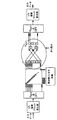
図1は従来型の受信機の構造を示すものである。図1には、無線周波数(RF)信号がアンテナ105によって受信され、RFフロントエンド110によって中間周波数(IF)にダウンコンバートされる。RFフロントエンド110は、低ノイズアンプ(LNAs)、フィルタとミキサ等の構成要素からなるものである。所望のチャネルは次に受信機のチャネライザ120によって抽出される。アナログチャネライザ120もまた、LNAs、ミキサとフィルタからなる。
【0004】
次に所望のチャネルがベースバンドにおいてRXベースバンド処理ユニット130によって処理されて受信デジタルデータストリームが生成される。今日、ベースバンド処理は一般的に、アナログからデジタルへの変換、デジタルフィルタリング、デシメーション、イコライゼーション、復調、チャネル復号化、デインターリービング、データ復号化、タイミング抽出等を含む処理である。
【0005】
図1に示した従来型の送信機は受信機と対称構造である。送信されたデータは第1に、データ符号化、インターリーブ、チャネル符号化、変調、補間フィルタリング、デジタルからアナログへの変換等からなるTXベースバンド処理ユニット140によって処理される。ベースバンドチャネルは次に、送信デチャネライザ150によってIF周波数に変換される。送信アナログチャネライザ150は、フィルタ、ミキサ及び低出力アンプから構成される。IF信号は次にRFに変換され、ミキサ、フィルタと高出力アンプから構成されるRFフロントエンド160で増幅される。最終的に、信号がアンテナ165から送信される。
【0006】
図1は、移動局(例えば移動電話)の単一チャネル受信機と送信機の従来構造を示すものである。基地局の場合には、同様の方法で複数のチャネルを処理する。受信機の側では、任意の点でパスが分離して、処理すべきチャネル毎のマルチパスを形成する。送信機の側では、複数チャネルは個別処理されて、次いで、任意の点で結合されてマルチチャネル信号を生成する。分離点及び結合点が異なるので、多様な基地局の受信機と送信機の構造を作成することができる。一層重要な点は、従来のアナログ及びデジタルインターフェースは、チャネライザとベースバンド処理ブロックとの間に位置することである。
【0007】
アナログチャネライザ/デチャネライザは設計と製造が複雑で、したがってコストが高くなる。より安価で製造が容易なチャネライザ/デチャネライザを提供するためには、将来のアナログとデジタルインターフェースは、RFフロントエンドとチャネライザブロックとの間の任意の位置に配置されることになるであろう。この種の将来の無線送受信機の構造は、マルチチャネル無線、ワイドバンドデジタルチューナ、ワイドバンド無線又はソフトウエア無線というような様々な名称で呼ばれているが、これらは何れもデジタルチャネライザ/デチャネライザを必要とするものである。
【0008】
フィルタリング、デシメーション/補間及び周波数変換を実行する効率的なデジタルチャネライザ/デチャネライザは、電力消費とチャネルベースあたりのダイエリアに関して大変重要な要素である。これらの構造の目標の1つは、単一の集積回路(IC)に可能な限り多くのチャネルを収容させることである。
【0009】
チャネライゼーションの効率的で柔軟性のある方法が、同じ出願人にかかる、「ワイドバンドマルチチャネルチャネライザ」と称するアメリカ特許出願第 号に開示されており、ここに当該明細書の記載を取り込むものとする。そこで開示された方法は、高速畳み込みアルゴリズム、周波数(フーリエ)領域での掛け算と時間領域での畳み込み演算との対応関係を用いて効率的にフィルタを実現するアルゴリズムである。
【0010】
図2Aと2Bは、それぞれチャネライザとデチャネライザに適用される改良高速畳み込みアルゴリズムを示すものである。図2Aでは、入力信号205がチャネライザに供給される。入力信号205は例えばADCのような前の処理から到来するデータストリームである。
【0011】
データストリーム205はまずη%重複ブロック発生器210によって処理される。この処理は重複のパーセンテージ、離散フーリエ変換(DFT)のサイズ、及び、重複の種類、つまり、以下に記述するような重複/加算(overlap/add)あるいは重複/保持(overlap/save)に基づくものである。重複と加算の場合には、データストリームを、長さがNDFT*(1−η)の重複の無い部分に分割し、NDFT*η個のゼロを追加して1つのブロックを作成する。重複と保持の場合には、データを、長さがN DFT *ηによって与えられた前のブロックと重複部を有する、長さがNDFTのブロックに分割する。
【0012】
次いで、その結果得られたブロックをDFTアルゴリズムに入力する。DFTアルゴリズムはブロック230で完了される。FFTのパイプライン処理の結果、FFT出力の順序は正しくない。したがって、ビン選択抽出ブロック240は、出力されたシーケンスの順序を入れ替えて必要なビンだけを選択することでこの問題を解消する必要がある。必要なビンの数はフィルタ係数260の数に依存する。
【0013】
積算器250で、選択されたビンにフィルタ周波数係数260を掛ける。離散フーリエ逆変換(逆DFTまたはIDFT)270をこの積算の結果に対して完了する。
【0014】
IDFTの出力はη%重複ブロック結合器280に挿入される。この結合演算は、ブロックの重複するパーセンテージと、重複/保持または重複/加算が採用されているか否かに依存する。重複及び加算又は重複及び保持の何れであっても、ブロックは前のブロックと長さNIDFT*η分だけ重複される。重複及び加算の場合には、ブロックの重複部分は前のブロックの対応する重複部分に加えられ、重複及び保持の場合には、ブロックの重複部分は単に廃棄される。重複及び加算と重複及び保持の何れの場合にも、ブロックの重複しない部分に対しては何らの演算もなされない。
【0015】
図2Bは、デチャネライザに適用される改良高速畳み込みアルゴリズムを示すものである。入力信号は、ADC処理のような前のプロセスからのデータストリーム202である。図2Aと異なり、入力されるデータストリームは、各チャネルに固有のものであり、複数のチャネルを結合したストリームではない。
【0016】
データストリーム202はまずη%重複ブロック発生器204で処理される。この処理は、基本的に、重複のパーセンテージ、DFTのサイズ、及び、重複の種類、つまり、重複/加算または重複/保持に基づくものである。重複及び加算の場合には、データストリームを、長さがNDFT*(1−η)の重複の無い部分に分割し、NDFT*η個のゼロを追加して1つのブロックを作成する。重複及び保持の場合には、データを、長さがN DFT *ηによって与えられる前のブロックと重複部を有する、長さがNDFTのブロックに分割する。
【0017】
次いで、離散フーリエ変換(DFT)206を前の演算の結果に対して完了する。当業者には、DFT206は選択的にFFTで実施できることを理解できるであろう。図2Aに示した受信機と比較して、DFT206の構造は小規模で、IDFT216の構造は大規模であり、受信機とは反対である。
【0018】
積算器208によってブロックにフィルタ周波数係数212を掛ける。周波数フィルタ係数212はインパルス応答のDFTと等価である。
【0019】
次いで、この掛け算の結果は、挿入ビンブロック214によって離散フーリエ逆変換(IDFT)216に入力され、IDFTアルゴリズムが完了する。IDFTアルゴリズムの結果はη%重複ブロック結合器224によって処理される。
【0020】
ブロックは、重複のパーセンテージ、および、重複/保持又は重複/加算が採用されているか否かに応じてブロック結合器224において結合される。重複及び加算又は重複及び保持の何れの場合でも、ブロックは、前のブロックと、長さがN IDFT *ηだけ重複される。重複及び加算の場合には、ブロックの重複部分は前のブロックの対応する重複部分に加えられ、重複及び保持の場合には、ブロックの重複部分は単に破棄される。重複及び加算と重複及び保持の何れの場合であっても、重複しない部分に対して何ら演算は行われない。
【0021】
「改良高速畳み込みアルゴリズムの柔軟性の改善」と題する本出願と同じ出願人によるアメリカ特許出願第 号の開示の内容をここに取り込む。当該文献には図2Aと2Bに示した処理の内容が詳細に記載されている。
【0022】
従来のチャネライザの状態で使用されている改良された高速畳み込みアルゴリズムでは、(IFFTで計算される)IDFTのポイントの数は2の累乗である。周波数領域のフィルタでは同じかやや少ない数の周波数係数が使用される。
【0023】
従来システムの状態の問題点は、IDFT/DFTサイズを選択する際、周波数成分の最大数が(IDFT/DFTの周波数成分の数に)制限されており、したがって、最大フィルタリジェクションもまた制限されていることである。このことは、必要なリジェクションが得られないか、あるいは周波数成分を適合させるためには2倍大きなIDFT/DFTを選択する必要があることを意味している。したがって、演算の数は、必要なフィルタリジェクションが少し増加すると飛躍的に増大することになる。簡単に言えば、従来の解決法の状態では、異なるシステムパラメータ(例えば、フィルタバンド幅、DFT/IDFTサイズとサンプリングレート)が非常に緊密に関連している。
【0024】
改良高速畳み込みアルゴリズムに基づくチャネライザのチャネル固有の部分では、受信機の小規模なIDFTと送信機の小規模なDFTとが、その計算のために多くの演算を必要とする。これは、電力消耗と、同じチップに組み込むことができる処理エレメントの限定的な数との双方に起因して、チャネライズ/デチャネライズすることができるチャネル数を制限する。ハードウェアに組み込まれたチャネル固有の部分が使用される場合、消費電力が主な制限要因になる。プログラム可能なプロセッサに基づく柔軟な構造を所望する場合、低電力消費であっても、演算数が、取扱い可能なチャネル数を制限する可能性がある。したがって、改良高速畳み込みアルゴリズムのチャネル固有の部分における演算数の削減に強い要請がある。
【0025】
【発明の要旨】
本発明は、アルゴリズムの柔軟性を拡大するために、上述の改良高速畳み込みアルゴリズムを改善することを目的とするものである。本発明の実施例では、受信機のIDFTの前に置かれた前処理段として折り畳みユニットを導入する。折り畳みユニットは、周波数領域で内側の周波数成分に外側の周波数成分を加えて周波数成分の数が削減された組(セット)を作成する。
【0026】
別の実施例では、送信機のDFTの後に置かれた後処理段として、展開ユニットを導入する。展開ユニットは、元の組の外側に、翻訳された元の成分を加えて周波数成分の組を拡張する。
【0027】
折り畳みと展開処理は、アルゴリズムの各チャネル固有の部分で行わなければならない1秒あたりの処理数を少なくすることで、改良高速畳み込みアルゴリズムの柔軟性を増大させる。さらに、チャネルあたりの処理の数が減少するので、1つのチップでより多くのチャネルを取り扱うことができる。
【0028】
図面の簡単な説明
本発明の上述の目的と特徴は添付の図面を参照して行う好ましい実施例に関する以下の記載によってより明瞭になるはずである。
図1は、従来の送信機と受信機を示すものである。
図2Aは、チャネライザに適用した改良高速畳み込みアルゴリズムを示すものである。
図2Bは、デチャネライザに適用した改良高速畳み込みアルゴリズムを示すものである。
図3は、本発明の実施例に基づくチャネライザに適用した改良高速畳み込みアルゴリズムを示すものである。
図4は、本発明の実施例に基づく折り畳み過程を示すものである。
図5は、本発明に基づき改良高速畳み込みアルゴリズムに折り畳み過程を導入した状態を示すものである。
図6は、本発明の実施例に基づく高次の折り畳み過程を示すものである。
図7は、本発明の実施例に基づきデチャネライザに適用された改良高速畳み込みアルゴリズムを示すものである。
図8は、本発明の実施例に基づく展開過程を示すものである。
図9は、本発明の改良高速畳み込みアルゴリズムに展開過程を導入した状態を示すものである。
図10は、本発明に基づく改良高速畳み込みアルゴリズムと従来の技術に基づく改良高速畳み込みアルゴリズムの性能を比較したものである。
【0029】
(発明の詳細な説明)
図3は、本発明の実施例に基づいてチャネライザに適用された改良高速畳み込みアルゴリズムを示すものである。図2Aに関する上述の記載と同様に、図3に示した本発明のチャネライザに適用された改良高速畳み込みアルゴリズムは、η%重複ブロック発生器310、大NDFT点DFT330、選択ビンブロック340、選択されたビンに周波数フィルター係数360を掛ける積算器350、小NIDFT点IDFT370と、上述と類似の処理を行うη%重複ブロック結合器380とを具備する。さらに、本実施例に基づくシステムは、本発明に係る折り畳み処理を行う折り畳みユニット390を具備する。
【0030】
折り畳みユニット390は、選択された周波数成分を別の周波数成分に加えるが、この処理を以後、周波数領域の「折り畳み(folding)」と称する。周波数の折り畳みは、外側の周波数成分を、残りの内側の周波数成分に加える処理である。
【0031】
図4は折り畳み処理を示すものである。図4では、左外側の4つの成分を右内側の4つの成分に加え、右外側の4つの成分を左内側の4つの成分に加えて、16の周波数成分を8つの周波数成分に折り畳んでいる。当業者であれば、信号は実部と虚部を有する複素信号なので、複素平面において畳み込みを行い、それにより、右外側の周波数成分は、畳み込まれるときには−90度の位相シフトが行われて図4に示した位置に加えられることになることが理解できるはずである。
【0032】
折り畳み処理の結果、元の16の周波数成分は8つの周波数成分に減縮される。本発明の折り畳み処理によって、周波数成分の組が少なくなり、当該過程を経ない場合よりも小さなIDFT370において処理が可能になる。図4に示した8点の組を形成する過程は、以下のように記載することができる。
【数1】

図5は、図3に示した改良高速畳み込みアルゴリズムにおける折り畳み処理の配置を示したものである。折り畳み処理は、ビンに周波数フィルタ係数をかけた後であって、データがIDFTに供給される前に実行される。図5から明らかなように、例示した積算器はD、B、A、Cで表示される4つの周波数成分を出力する。折り畳みユニットは外側の周波数成分DとCとを内側の成分AとBとに折り畳んでIDFTが処理するのに必要な周波数成分の数を削減する。
【0034】
本発明の実施例によれば、周波数領域での折り畳みは、高次に拡張することができる。つまり、図6に示したように、周波数成分を、内側に折り畳んで、複数回加えることができる。このことは、3以上の成分が一緒に加えられて、IDFTへの1つの入力成分を形成することを意味している。図6に示したように、X 1 −X 22 で表示された22の周波数成分は、本発明に基づく折り畳み処理を経て4つの成分Y1−Y4に折り畳まれる。この折り畳み処理により、4点DFTが1回の演算で22の周波数成分を処理することが可能になる。
【0035】
キャリアから遠い位置でフィルタリジェクションを高くする必要があり、キャリアに近い位置で要件がゆるい場合には、この高次の折り畳みが特に有用である。高次の折り畳みに関する一般式を以下に示す。N点のIDFTによって処理される1組における出力周波数成分Ykは以下のように表現される。
【数2】
【0036】
図7は、本発明の実施例に基づいてデチャネライザに適用される改良高速畳み込みアルゴリズムを示す図である。図2Bで示した実施例と同様、図7に示した本発明の実施例に係るデチャネライザに適用された改良高速畳み込みアルゴリズムは、η%重複ブロック発生器704、小NDFT点DFT706と、ビンに周波数フィルタ係数712を掛ける積算器708、挿入ビンブロック714、大NIDFT点IDFT716、及び、前述と同様に演算するη%重複ブロック結合器724を具備する。さらに、本実施例に基づくシステムは、本発明に係る展開処理を実施する展開ユニット730を有する。
【0037】
展開ユニット730は、元の組の外側に翻訳した元の成分を加えることによって、DFT706から出力された周波数成分の組を拡張する。図8は展開の概念を示したものである。図8において、16点DFTから入来した16の周波数成分から24点の組が作成される。図に示したように、元の組の最も左側の4つの周波数成分を、元の組の最も右側の周波数成分の右外に加え、元の組の最も右側の4つの成分を、元の成分の最も左の左外に加える。結果的に、新しい24点の周波数応答が生成される。新しい24点の周波数応答は、次に24点の周波数応答(例えば、24の周波数フィルタ係数)と掛け合わせられるので、大きなDFT演算が不要である。
【0038】
図8に示した24点の組の形成は以下のように記述される。
【数3】
【0039】
図9は、図7に示した改良高速畳み込みアルゴリズムにおける展開処理の配置を示すものである。展開処理は、DFT演算後であって、周波数フィルタ係数をデータに掛ける前に行われる。図9から明らかなように、例示したDFTは、C、B、AとDで表示された4つの周波数成分を出力する。展開ユニットは、成分CとDとを元の組の成分の外側に加えて6つの周波数成分の組(D、C、B、A、DとC)を作成する。
【0040】
展開処理は、周波数応答積算に供給された少数のDFT周波数成分を複数回使用するように高次に拡張することもできる。
【0041】
高次を含む展開の一般式は下記のとおりである。N点DFTの成分を展開することによって形成される出力周波数成分YCo+k+N*nは以下のように表現される。
【数4】
【0042】
上述のように、受信機で周波数領域での折り畳みを行うことによって、広帯域折り返し雑音を排除するのに十分な広帯域のフィルタ応答をDFT出力に掛けることができ、この演算の結果を最も近い近隣チャネルからの折り返し雑音が入らないような形で最も小さいIDFTに折り畳むことができる。送信機では周波数領域展開の概念を使用して、フィルタ応答よりも小さなDFT出力を有し、周波数応答と掛け算を行う前に、必要な幅に前記DFT出力を拡張することができる。
【0043】
周波数領域の折り畳みと展開によって、周波数領域のフィルタに関する制限を排除するとともに、DFT/IDFT長のフィルタリング要求を切り離すことによって柔軟性が改善される。折り畳み/展開は、フィルタバンド幅やストップバンド圧縮の変更に無関係に正しいサンプリングレートを得るために使用することができる。
【0044】
周波数領域での折り畳みと展開は、改良高速畳み込みアルゴリズムのチャネル固有の部分で実行すべき単位秒あたりの演算数を大幅に減少させる。また、必要な記憶容量も削減される。チャネルあたりの処理の数が減少するので、同じチップでより多くのチャネルを取り扱うことができる。結果として、プロセッサベースのアーキテクチャが一層実現可能になる。
【0045】
本発明は、サンプリングレートの変更を伴い、特にストップバンドの要求が非常に厳しい場合に、すべての形式の高速畳み込みアルゴリズムに対して適用することができる。本発明によってもたらされる処理数の減少は、IDFT/DFTに起因する処理の総数に部分的に依存する。IDFTの大きさを32点から16点に削減することによって、IDFTをラディックス−2IFFTで計算するなら、必要な掛け算の演算回数は88から24に減少する。この3.7分の1への減少は、電力消費量の減少に反映される。算術的な演算の回数(足し算と掛け算)は、496から176に、2.8分の1に減少する。
【0046】
図10は、従来のアルゴリズムの状態と本発明の折り畳みアルゴリズムとの間の(記憶演算を除く)演算の複雑さを、1秒あたりの100万回演算の単位で比較したものである。比較は、サンプリング周波数61.44MHz、全デシメーションは512xの条件で行った。図から明らかなように、本発明の折り畳みアルゴリズムによって、従来のアルゴリズムよりも多数のチャネルを処理することが可能になる。
【0047】
本発明の原理、好ましい実施例及び動作モードについて述べた。しかし、本発明が上述の特定の実施例に限定されるものと解釈してはならない。上述の実施例は限定的な意味ではなく説明のために述べられたもので、添付の特許請求の範囲によって規定される本発明の技術的範囲から逸脱せず、多くの変形を行うことができることは当業者には容易に理解できるものである。
【図面の簡単な説明】
【図1】 図1は、従来の送信機と受信機を示すものである。
【図2】 図2Aは、チャネライザに適用した改良高速畳み込みアルゴリズムを示すもの、図2Bは、デチャネライザに適用した改良高速畳み込みアルゴリズムを示すものである。
【図3】 図3は、本発明の実施例に基づくチャネライザに適用した改良高速畳み込みアルゴリズムを示すものである。
【図4】 図4は、本発明の実施例に基づく折り畳み過程を示すものである。
【図5】 図5は、本発明に基づき改良高速畳み込みアルゴリズムに折り畳み過程を導入した状態を示すものである。
【図6】 図6は、本発明の実施例に基づく高次の折り畳み過程を示すものである。
【図7】 図7は、本発明の実施例に基づきデチャネライザに適用された改良高速畳み込みアルゴリズムを示すものである。
【図8】 図8は、本発明の実施例に基づく展開過程を示すものである。
【図9】 図9は、本発明の改良高速畳み込みアルゴリズムに展開過程を導入した状態を示すものである。
【図10】 図10は、本発明に基づく改良高速畳み込みアルゴリズムと従来の技術に基づく改良高速畳み込みアルゴリズムの性能を比較したものである。[0001]
[Technical background]
The present invention relates generally to wireless communication systems, and more specifically to the use of improved fast convolution algorithms in channelizers and dechannelizers of wireless communication systems.
[0002]
In applications of cellular systems, terrestrial mobile radio (LMR), satellite, wireless local area network (WLANS) and other radio base stations for communication systems, many transmit and receive channels are handled simultaneously. In the future, mobile station, i.e., the mobile phone will also will have this feature. Such systems, respectively in the receiver and transmitter comprises a digital channelization and de channelization structure. Channelization and dechannelization refer to filtering, decimation / interpolation and frequency conversion of transmitted and received signals.
[0003]
FIG. 1 shows the structure of a conventional receiver. In FIG. 1, a radio frequency (RF) signal is received by an
[0004]
The desired channel is then processed at baseband by RX
[0005]
The conventional transmitter shown in FIG. 1 is symmetrical with the receiver. The transmitted data is first processed by a TX
[0006]
FIG. 1 shows a conventional structure of a single channel receiver and transmitter of a mobile station (eg mobile phone ). In the case of a base station, a plurality of channels are processed in the same manner. On the receiver side, the paths are separated at arbitrary points to form a multipath for each channel to be processed. On the transmitter side, the multiple channels are individually processed and then combined at any point to produce a multi-channel signal. Since the separation point and the point of attachment is different, it is possible to create a structure of a transmitter and a receiver of a variety of base stations. More importantly, conventional analog and digital interface is that located between the channelizer and baseband processing blocks.
[0007]
Analog channelizers / dechannelizers are complex to design and manufacture and are therefore expensive. In order to provide a more inexpensive and is easy to manufacture channelizer / Dechaneraiza the future analog and digital interface will become to be located at any position between the RF front end and channelizer blocks. This type of future radio transceiver structure is called by various names such as multi-channel radio, wideband digital tuner, wideband radio or software defined radio, all of which are digital channelizer / dechannelizer. Is what you need.
[0008]
An efficient digital channelizer / dechannelizer that performs filtering, decimation / interpolation and frequency conversion is a very important factor in terms of power consumption and die area per channel base. One of the goals of these structures is to accommodate as many channels as possible on a single integrated circuit (IC).
[0009]
An efficient and flexible method of channelization is described in US patent application no. “Wideband Multi-Channel Channelizer” to the same applicant. Which is incorporated herein by reference. The method disclosed there is a fast convolution algorithm, an algorithm that efficiently implements a filter using the correspondence between multiplication in the frequency (Fourier) domain and convolution in the time domain.
[0010]
2A and 2B illustrate improved fast convolution algorithms applied to the channelizer and dechannelizer, respectively. In FIG. 2A, an input signal 205 is supplied to the channelizer. The input signal 205 is a data stream coming from a previous process such as an ADC.
[0011]
Data stream 205 is first processed by η%
[0012]
The resulting block is then input into the DFT algorithm. The DFT algorithm is completed at
[0013]
The
[0014]
The output of IDFT is inserted into η% overlapping block combiner 280. This join operation depends on the overlapping percentage of blocks and whether overlap / hold or overlap / add is employed . It is either overlap and add or overlap and hold block is overlapped by the previous block length N IDFT * eta min. In the case of overlap and addition, the overlap portion of the block is added to the corresponding overlap portion of the previous block, and in the case of overlap and hold , the overlap portion of the block is simply discarded . In any case of overlap and addition and overlap and hold , no operation is performed on the non-overlapping portion of the block.
[0015]
FIG. 2B shows an improved fast convolution algorithm applied to the dechannelizer. The input signal is a data stream 202 from a previous process such as ADC processing. Unlike FIG. 2A, the input data stream is unique to each channel, and is not a stream in which a plurality of channels are combined .
[0016]
Data stream 202 is first processed by η%
[0017]
Then, to complete the discrete Fourier transform (DFT) 206 the result of the previous calculation. Those skilled in the art,
[0018]
An
[0019]
The result of this multiplication is then input to the inverse discrete Fourier transform (IDFT) 216 by the
[0020]
Blocks are combined in
[0021]
US patent application filed by the same applicant as this application entitled "Improved Flexibility of Improved Fast Convolution Algorithm" The content of the disclosure of the issue is incorporated here. This document describes the details of the processing shown in FIGS. 2A and 2B.
[0022]
In the improved fast convolution algorithm used in the conventional channelizer state , the number of IDFT points (calculated with IFFT) is a power of two. The frequency domain filters use the same or slightly less frequency coefficients.
[0023]
The problem with the state of the conventional system is that when selecting the IDFT / DFT size, the maximum number of frequency components is limited (to the number of frequency components of IDFT / DFT), so the maximum filter rejection is also limited. It is that. This means that the required rejection cannot be obtained or that an IDFT / DFT that is twice as large must be selected to adapt the frequency components. Therefore, the number of operations increases dramatically when the required filter rejection increases slightly . Simply put, in the state of conventional solutions, different system parameters (eg, filter bandwidth, DFT / IDFT size and sampling rate) are very closely related.
[0024]
In the channel-specific part of the channelizer based on an improvement fast convolution algorithm, the small DFT with small IDFT receiver transmitter requires many operations for their computations. This limits the number of channels that can be channelized / dechannelized due to both power consumption and the limited number of processing elements that can be incorporated into the same chip . When channel-specific parts built into the hardware are used , power consumption becomes the main limiting factor. If a flexible structure based on a programmable processor is desired, the number of operations can limit the number of channels that can be handled, even at low power consumption. Therefore, there is a strong demand for reducing the number of operations in the channel- specific portion of the improved fast convolution algorithm.
[0025]
SUMMARY OF THE INVENTION
The present invention aims to improve the above-described improved fast convolution algorithm in order to expand the flexibility of the algorithm. In an embodiment of the present invention, it introduces a folding unit as a pre-processing stage placed in front of the IDFT in the receiver. The folding unit creates a set in which the number of frequency components is reduced by adding the outer frequency component to the inner frequency component in the frequency domain.
[0026]
In another embodiment, a deployment unit is introduced as a post-processing stage located after the transmitter's DFT. The expansion unit expands the set of frequency components by adding the translated original component outside the original set.
[0027]
The folding and unfolding process increases the flexibility of the improved fast convolution algorithm by reducing the number of processes per second that must be performed on each channel-specific portion of the algorithm. Furthermore, since the number of processes per channel is reduced, a single chip can handle more channels.
[0028]
BRIEF DESCRIPTION OF THE DRAWINGS The above objects and features of the present invention will become more apparent from the following description of a preferred embodiment with reference to the accompanying drawings.
FIG. 1 shows a conventional transmitter and receiver.
FIG. 2A shows an improved fast convolution algorithm applied to the channelizer.
FIG. 2B shows an improved fast convolution algorithm applied to the dechannelizer.
FIG. 3 shows an improved fast convolution algorithm applied to a channelizer according to an embodiment of the present invention.
FIG. 4 shows a folding process according to an embodiment of the present invention.
FIG. 5 shows a state in which a folding process is introduced into the improved fast convolution algorithm according to the present invention.
FIG. 6 illustrates a high-order folding process according to an embodiment of the present invention.
FIG. 7 illustrates an improved fast convolution algorithm applied to a dechannelizer according to an embodiment of the present invention.
FIG. 8 shows a development process according to an embodiment of the present invention.
FIG. 9 shows a state in which a development process is introduced into the improved fast convolution algorithm of the present invention.
FIG. 10 compares the performance of the improved fast convolution algorithm based on the present invention and the improved fast convolution algorithm based on the prior art.
[0029]
( Detailed description of the invention )
FIG. 3 illustrates an improved fast convolution algorithm applied to a channelizer according to an embodiment of the present invention. In the same manner as described above with reference to figure 2A, it applied improved fast convolution algorithm Ji Yaneraiza of the present invention shown in FIG. 3, eta%
[0030]
[0031]
Figure 4 shows a folding process. In Figure 4, in addition to the four components of four components of the right inner outer left, in addition to the four components of four components left inside the outer right and fold the 16 frequency components into 8 frequency components . Those skilled in the art, since the signal is a complex signal having a real part and an imaginary part, have a row convolution in the complex plane, thereby, the frequency component of the right outer is made -90 degrees phase shift when convolved It should be understood that this will be added to the position shown in FIG.
[0032]
Result of folding processing, the frequency components of the original 16 is Genchijimi into 8 frequency components. The folding process of the present invention, the set of frequency components is reduced, allowing Oite processed into smaller IDFT370 than without through the process. The process of forming the 8-point set shown in FIG. 4 can be described as follows.
[Expression 1]
FIG. 5 shows the arrangement of the folding process in the improved fast convolution algorithm shown in FIG. The folding process is performed after the frequency filter coefficients are applied to the bins and before the data is supplied to the IDFT. As is apparent from FIG. 5, the illustrated integrator outputs four frequency components indicated by D, B, A, and C. Folding unit reduces the number of frequency components necessary for IDFT folded and frequency components D and C of the outer side and inner side of the components A and B are processed.
[0034]
According to an embodiment of the present invention, fold folding in the frequency domain, it can be extended to higher order. That is, as shown in FIG. 6, the frequency component can be folded inward and added multiple times . This means that three or more components are added together to form one input component to the IDFT . As shown in FIG. 6, the 22 frequency components indicated by X 1 -X 22 are folded into four components Y 1 -Y 4 through the folding process according to the present invention. With this folding process, the four-point DFT can process 22 frequency components in one operation.
[0035]
This higher order folding is particularly useful when the filter rejection needs to be high at locations far from the carrier and the requirements are loose at locations near the carrier. The general expression for the higher order of folding are shown below. The output frequency component Y k in one set processed by the N-point IDFT is expressed as follows.
[Expression 2]
[0036]
FIG. 7 is a diagram illustrating an improved fast convolution algorithm applied to a dechannelizer according to an embodiment of the present invention. Similar to the embodiment shown in Figure 2B, the applied modified fast convolution algorithm Dechaneraiza according to an embodiment of the present invention shown in FIG. 7, eta%
[0037]
The
[0038]
The formation of the 24-point set shown in FIG. 8 is described as follows.
[Equation 3]
[0039]
FIG. 9 shows an arrangement of expansion processing in the improved high-speed convolution algorithm shown in FIG. The expansion process is performed after the DFT operation and before the frequency filter coefficient is applied to the data. As is clear from FIG. 9, the illustrated DFT outputs four frequency components represented by C, B, A, and D. The expansion unit adds the components C and D to the outside of the original set of components to create a set of six frequency components (D, C, B, A, D and C).
[0040]
The expansion process can also be extended to higher orders so that a small number of DFT frequency components supplied to the frequency response integration are used multiple times .
[0041]
The higher-order including deployment of the general formula is as follows. The output frequency component Y Co + k + N * n formed by expanding the components of the N-point DFT is expressed as follows.
[Expression 4]
[0042]
As described above, by performing the convolution fold in the frequency domain at the receiver, the filter response of sufficient broadband to eliminate broadband aliasing can be subjected to DFT output closest to the result of this calculation neighbor it can be folded folding smallest IDFT in a way aliasing noise from the channel does not turn. Using the concept of frequency domain expansion in the transmitter, than the filter response has a smaller DFT output, before the frequency response and multiplication can be extended the DFT output to the required width.
[0043]
By folding and deployment in the frequency domain, while eliminating the restrictions on the filter in the frequency domain, the flexibility is improved by separating filtering request DFT / IDFT length. Folding / unfolding can be used to obtain the correct sampling rate regardless of changes in filter bandwidth or stopband compression.
[0044]
Folding and unfolding in the frequency domain greatly reduces the number of operations per second that must be performed on the channel-specific portion of the improved fast convolution algorithm. Also, the necessary storage capacity is reduced. Since the number of processes per channel is reduced, more channels can be handled on the same chip. As a result, a processor- based architecture becomes more feasible.
[0045]
The present invention involves a change in the sampling rate, especially when the request of the stop band is very severe, it can be applied to fast convolution algorithm all forms. The reduction in the number of processes provided by the present invention depends in part on the total number of processes due to IDFT / DFT. By reducing the IDFT size from 32 points to 16 points, if the IDFT is calculated by Radix-2 IFFT, the number of multiplication operations required is reduced from 88 to 24. This reduction by a factor of 3.7 is reflected in the reduction in power consumption. The number of arithmetic operations (addition and multiplication) decreases from 496 to 176 by a factor of 2.8.
[0046]
FIG. 10 compares the operation complexity (excluding storage operations ) between the state of the conventional algorithm and the folding algorithm of the present invention in units of 1 million operations per second. The comparison was performed under the conditions of a sampling frequency of 61.44 MHz and a total decimation of 512x. As can be seen, the folding algorithm of the present invention, it is possible to process a large number of channels than conventional algorithms.
[0047]
The principles, preferred embodiments and modes of operation of the present invention have been described. However, this invention should not be construed as limited to the particular embodiments described above. The embodiments described above have been set forth for purposes of illustration and not limitation, and many variations can be made without departing from the scope of the invention as defined by the appended claims. Can be easily understood by those skilled in the art.
[Brief description of the drawings]
FIG. 1 shows a conventional transmitter and receiver.
FIG. 2A shows an improved fast convolution algorithm applied to the channelizer, and FIG. 2B shows an improved fast convolution algorithm applied to the dechannelizer.
FIG. 3 shows an improved fast convolution algorithm applied to a channelizer according to an embodiment of the present invention.
FIG. 4 shows a folding process according to an embodiment of the present invention.
FIG. 5 shows a state in which a folding process is introduced into the improved fast convolution algorithm according to the present invention.
FIG. 6 illustrates a high-order folding process according to an embodiment of the present invention.
FIG. 7 illustrates an improved fast convolution algorithm applied to a dechannelizer according to an embodiment of the present invention.
FIG. 8 shows a development process based on an embodiment of the present invention.
FIG. 9 shows a state in which a development process is introduced into the improved fast convolution algorithm of the present invention.
FIG. 10 is a comparison of the performance of an improved fast convolution algorithm based on the present invention and an improved fast convolution algorithm based on the prior art.
Claims (9)
前記ブロックに対してNDFT点の離散フーリエ変換(DFT)を実施して周波数成分を作成する手段と、
周波数成分を選択する手段と、
前記選択した周波数成分と周波数フィルタ係数とを積算する積算器と、
外側の周波数成分を内側の周波数成分に加えることによって、前記積算された周波数成分をより少数の周波数成分に折り畳む手段と、
前記折り畳まれた周波数成分に対してNIDFT点の離散逆フーリエ変換(IDFT)を実施して、フィルタ処理されたデータブロックを作成する手段と、
フィルタ処理されたデータブロックを連続したデータストリームに結合するη%の重複ブロック結合器と、
を具備するチャネライザに適用される改良高速畳み込みアルゴリズムを改善するシステム。Converting the received data stream into a plurality of blocks, and eta% overlap block generator,
Means to create a frequency component to implement the discrete Fourier transform of the N DFT points (DFT) to said block,
Means for selecting frequency components;
An integrator for integrating the selected frequency component and the frequency filter coefficient;
By adding outer frequency components to inner frequency components, means for folding folding the accumulated frequency components into a smaller number of frequency components,
And means for performing inverse discrete Fourier transform of the N IDFT point (IDFT), to create the filtered data blocks to the folded collapsed frequency components,
An η% overlapping block combiner that combines the filtered data blocks into a continuous data stream ;
A system for improving an improved fast convolution algorithm applied to a channelizer comprising:
データブロックをN DFT 点の離散フーリエ変換(DFT)処理して周波数成分を作成する過程と、
該周波数成分を選択する過程と、
選択した周波数成分と周波数フィルタ成分とを積算する過程と、
外側の周波数成分を内側の成分に加えることによって、前記積算された周波数成分をより少数の周波数成分に折り畳む過程と、
折り畳まれた周波数成分に対して、NIDFT点の離散逆フーリエ変換(IDFT)を実施して、フィルタ処理されたデータブロックを作成する過程と、
フィルタ処理されたデータブロックを連続したデータストリームに結合する過程と、
を含む、チャネライザに適用された改良高速畳み込みアルゴリズムの改善方法。 A process of converting the received data stream into η% overlapping blocks;
A process of creating a frequency component data block by discrete Fourier transform (DFT) processing of the N DFT point,
Selecting the frequency component;
A step of integrating the selected frequency component and the frequency filter components,
Folding the integrated frequency component into fewer frequency components by adding an outer frequency component to the inner component ;
About the fold folded frequency components, the method comprising implemented discrete inverse Fourier transform of N IDFT point (IDFT), to create the filtered data blocks,
A step of combining the filtered data blocks to the continuous data stream,
A method for improving an improved fast convolution algorithm applied to a channelizer, including:
前記複数のブロックに対してNDFT点の離散フーリエ変換(DFT)を実施して元の周波数成分の組を作成する手段と、
元の周波数成分を元の周波数成分の組の外側に加えることによって、より少数の周波数成分をより多数の周波数成分に拡張するように、前記元の周波数成分の組を展開する手段と、
前記より多数の周波数成分と周波数フィルタ係数とを積算する積算器と、
前記積算された周波数成分をNIDFT点の離散逆フーリエ変換(IDFT)に挿入する手段と、
積算された周波数成分に対して、N IDFT 点の離散逆フーリエ変換を(IDFT)実施して、データブロックを作成する手段と、
当該データブロックを連続したデータストリームに結合するη%の重複ブロック結合器と、
を具備するデチャネライザに適用される改良高速畳み込みアルゴリズムを改善するシステム。Converting the data stream into a plurality of blocks, and eta% overlap block generator,
Means for performing a discrete Fourier transform (DFT) of NDFT points on the plurality of blocks to create a set of original frequency components;
Means for expanding the set of original frequency components to expand a smaller number of frequency components to a larger number of frequency components by adding the original frequency components outside the set of original frequency components;
An accumulator that integrates the greater number of frequency components and frequency filter coefficients;
Means for inserting the integrated frequency component inverse discrete Fourier transform of the N IDFT point (IDFT),
Means for performing a discrete inverse Fourier transform (IDFT) of N IDFT points on the accumulated frequency component to create a data block ;
Η% overlapping block combiner that combines the data block into a continuous data stream ;
A system for improving an improved fast convolution algorithm applied to a dechannelizer comprising:
重複するデータブロックに対してNDFT点の離散フーリエ変換(DFT)を実施して元の周波数成分の組を作成する過程と、
元の周波数成分を前記元の周波数成分の組の外側に加えることによって、より少数の周波数成分をより多数の周波数成分に拡張するように、前記元の周波数成分の組を展開する過程と、
前記より多数の周波数成分と周波数フィルタ係数とを積算する過程と、
積算された周波数成分に対して、NIDFT点の離散逆フーリエ変換(IDFT)を実施して、データブロックを作成する過程と、
当該データブロックを連続したデータストリームに結合する過程と、
を含む、デチャネライザに適用された改良高速畳み込みアルゴリズムの改善方法。 Converting the data stream into a plurality of η% overlapping blocks;
Performing a discrete Fourier transform (DFT) of N DFT points on overlapping data blocks to create a set of original frequency components ;
Expanding the set of original frequency components to expand a smaller number of frequency components to a larger number of frequency components by adding the original frequency components to the outside of the set of original frequency components ;
Integrating the greater number of frequency components and frequency filter coefficients;
Performing a discrete inverse Fourier transform (IDFT) of N IDFT points on the accumulated frequency component to create a data block ;
Combining the data blocks into a continuous data stream;
A method for improving an improved fast convolution algorithm applied to a dechannelizer, including:
Applications Claiming Priority (3)
| Application Number | Priority Date | Filing Date | Title |
|---|---|---|---|
| US09/163,298 | 1998-09-30 | ||
| US09/163,298 US6247035B1 (en) | 1998-09-30 | 1998-09-30 | Reduced complexity and increased flexibility modified fast convolution algorithm |
| PCT/SE1999/001693 WO2000019654A1 (en) | 1998-09-30 | 1999-09-24 | Reduced complexity and increased flexibility modified fast convolution algorithm |
Publications (3)
| Publication Number | Publication Date |
|---|---|
| JP2002526977A JP2002526977A (en) | 2002-08-20 |
| JP2002526977A5 JP2002526977A5 (en) | 2008-10-30 |
| JP4384816B2 true JP4384816B2 (en) | 2009-12-16 |
Family
ID=22589378
Family Applications (1)
| Application Number | Title | Priority Date | Filing Date |
|---|---|---|---|
| JP2000573035A Expired - Fee Related JP4384816B2 (en) | 1998-09-30 | 1999-09-24 | Improved fast superposition algorithm with reduced complexity and increased flexibility |
Country Status (9)
| Country | Link |
|---|---|
| US (1) | US6247035B1 (en) |
| EP (1) | EP1114537B1 (en) |
| JP (1) | JP4384816B2 (en) |
| KR (1) | KR20010075519A (en) |
| CN (1) | CN1171414C (en) |
| CA (1) | CA2344634A1 (en) |
| DE (1) | DE69926382T2 (en) |
| TW (1) | TW472198B (en) |
| WO (1) | WO2000019654A1 (en) |
Families Citing this family (11)
| Publication number | Priority date | Publication date | Assignee | Title |
|---|---|---|---|---|
| CN1153456C (en) * | 1998-03-04 | 2004-06-09 | 皇家菲利浦电子有限公司 | Method and device for watermark detection |
| US6611855B1 (en) | 1999-06-21 | 2003-08-26 | Telefonaktiebolaget Lm Ericsson (Publ) | Flexible and efficient channelizer architecture |
| FR2817100B1 (en) * | 2000-11-17 | 2003-08-22 | Cit Alcatel | METHOD FOR OPTIMIZING THE PERFORMANCE OF A TRANSMITTER FOR A MOBILE RADIO COMMUNICATION SYSTEM |
| CA2375823A1 (en) * | 2002-03-11 | 2003-09-11 | Catena Networks Canada Inc. | Improved equalization scheme for adsl receivers in presence of an under-sampled or over-sampled transmit ifft |
| WO2003079594A1 (en) * | 2002-03-11 | 2003-09-25 | Catena Networks, Inc. | Equalization scheme for dsl receivers in presence of an under-sampled or over-sampled transmit idft |
| KR100790534B1 (en) * | 2006-08-01 | 2008-01-02 | 주식회사 몬도시스템즈 | Signal processing apparatus and method using convolution overlap-hold technique |
| WO2010076727A1 (en) | 2008-12-29 | 2010-07-08 | Nxp B.V. | Fractional frequency and sampling-rate change in the frequency domain |
| US8346091B2 (en) | 2009-04-29 | 2013-01-01 | Andrew Llc | Distributed antenna system for wireless network systems |
| EP2658124B1 (en) * | 2010-12-21 | 2020-05-20 | Nec Corporation | Digital filter circuit and digital filter control method |
| BR112015009601A2 (en) | 2012-10-31 | 2017-07-04 | Commscope Technologies Llc | telecommunication system and distributed antenna system |
| CN109596649A (en) * | 2018-11-29 | 2019-04-09 | 昆明理工大学 | A kind of method and device that host element concentration is influenced based on convolutional network coupling microalloy element |
Family Cites Families (9)
| Publication number | Priority date | Publication date | Assignee | Title |
|---|---|---|---|---|
| JPH0620855B2 (en) * | 1984-07-31 | 1994-03-23 | ヤマハ発動機株式会社 | Automobile |
| GB9104186D0 (en) | 1991-02-28 | 1991-04-17 | British Aerospace | Apparatus for and method of digital signal processing |
| US5270953A (en) | 1991-05-23 | 1993-12-14 | Rockwell International Corporation | Fast convolution multiplier |
| US5535240A (en) | 1993-10-29 | 1996-07-09 | Airnet Communications Corporation | Transceiver apparatus employing wideband FFT channelizer and inverse FFT combiner for multichannel communication network |
| US5485395A (en) * | 1994-02-14 | 1996-01-16 | Brigham Young University | Method for processing sampled data signals |
| US5583792A (en) * | 1994-05-27 | 1996-12-10 | San-Qi Li | Method and apparatus for integration of traffic measurement and queueing performance evaluation in a network system |
| US5794046A (en) * | 1994-09-29 | 1998-08-11 | International Business Machines Corporation | Method and system for debugging parallel and distributed applications |
| US5930231A (en) * | 1995-06-30 | 1999-07-27 | Scientific-Atlanta, Inc. | Block spectrum receiver for a broadband communications system |
| US5890106A (en) * | 1996-03-19 | 1999-03-30 | Dolby Laboratories Licensing Corporation | Analysis-/synthesis-filtering system with efficient oddly-stacked singleband filter bank using time-domain aliasing cancellation |
-
1998
- 1998-09-30 US US09/163,298 patent/US6247035B1/en not_active Expired - Lifetime
-
1999
- 1999-09-24 EP EP99969864A patent/EP1114537B1/en not_active Expired - Lifetime
- 1999-09-24 DE DE69926382T patent/DE69926382T2/en not_active Expired - Lifetime
- 1999-09-24 CN CNB998138991A patent/CN1171414C/en not_active Expired - Fee Related
- 1999-09-24 KR KR1020017004142A patent/KR20010075519A/en not_active Withdrawn
- 1999-09-24 CA CA002344634A patent/CA2344634A1/en not_active Abandoned
- 1999-09-24 JP JP2000573035A patent/JP4384816B2/en not_active Expired - Fee Related
- 1999-09-24 WO PCT/SE1999/001693 patent/WO2000019654A1/en not_active Ceased
- 1999-10-02 TW TW088117011A patent/TW472198B/en not_active IP Right Cessation
Also Published As
| Publication number | Publication date |
|---|---|
| KR20010075519A (en) | 2001-08-09 |
| JP2002526977A (en) | 2002-08-20 |
| WO2000019654A1 (en) | 2000-04-06 |
| CA2344634A1 (en) | 2000-04-06 |
| CN1328732A (en) | 2001-12-26 |
| US6247035B1 (en) | 2001-06-12 |
| DE69926382D1 (en) | 2005-09-01 |
| CN1171414C (en) | 2004-10-13 |
| TW472198B (en) | 2002-01-11 |
| DE69926382T2 (en) | 2006-04-27 |
| EP1114537B1 (en) | 2005-07-27 |
| EP1114537A1 (en) | 2001-07-11 |
Similar Documents
| Publication | Publication Date | Title |
|---|---|---|
| JP4409771B2 (en) | Generality enhancement for improved fast convolution algorithm | |
| JP4056700B2 (en) | Apparatus and method for digital channel separation and channel integration | |
| EP1540941B1 (en) | Partial band reconstruction of frequency channelized filters | |
| JP3578990B2 (en) | Decimation filtering device and method | |
| US7035888B2 (en) | Digital sampling rate converter for compensation for drop of in-band signal | |
| JP4384816B2 (en) | Improved fast superposition algorithm with reduced complexity and increased flexibility | |
| CN109889213B (en) | Channelization method, apparatus and computer storage medium | |
| EP1121754B1 (en) | Odd-transform fast convolution | |
| US7372927B2 (en) | Digital filter for software-defined radio system, digital intermediate frequency signal processing apparatus having the digital filter, and method thereof | |
| Mahesh et al. | Low complexity flexible filter banks for uniform and non-uniform channelisation in software radios using coefficient decimation | |
| CN101473535A (en) | Method for processing a digital input signal in a digital domain and digital filter circuit for processing a digital input signal | |
| AU755991B2 (en) | Reduced complexity and increased flexibility modified fast convolution algorithm | |
| CN107404331A (en) | The method and apparatus for handling digital composite signal | |
| Tecpanecatl-Xihuitl et al. | Low complexity decimation filter for multi-standard digital receivers | |
| Kiessling et al. | A software radio architecture for multi-channel digital upconversion and downconversion using generalized polyphase filterbanks with frequency offset correction |
Legal Events
| Date | Code | Title | Description |
|---|---|---|---|
| A621 | Written request for application examination |
Free format text: JAPANESE INTERMEDIATE CODE: A621 Effective date: 20060914 |
|
| A131 | Notification of reasons for refusal |
Free format text: JAPANESE INTERMEDIATE CODE: A131 Effective date: 20080605 |
|
| A524 | Written submission of copy of amendment under article 19 pct |
Free format text: JAPANESE INTERMEDIATE CODE: A524 Effective date: 20080905 |
|
| TRDD | Decision of grant or rejection written | ||
| A01 | Written decision to grant a patent or to grant a registration (utility model) |
Free format text: JAPANESE INTERMEDIATE CODE: A01 Effective date: 20090901 |
|
| A01 | Written decision to grant a patent or to grant a registration (utility model) |
Free format text: JAPANESE INTERMEDIATE CODE: A01 |
|
| A61 | First payment of annual fees (during grant procedure) |
Free format text: JAPANESE INTERMEDIATE CODE: A61 Effective date: 20090928 |
|
| FPAY | Renewal fee payment (event date is renewal date of database) |
Free format text: PAYMENT UNTIL: 20121002 Year of fee payment: 3 |
|
| R150 | Certificate of patent or registration of utility model |
Free format text: JAPANESE INTERMEDIATE CODE: R150 |
|
| FPAY | Renewal fee payment (event date is renewal date of database) |
Free format text: PAYMENT UNTIL: 20131002 Year of fee payment: 4 |
|
| R250 | Receipt of annual fees |
Free format text: JAPANESE INTERMEDIATE CODE: R250 |
|
| R250 | Receipt of annual fees |
Free format text: JAPANESE INTERMEDIATE CODE: R250 |
|
| R250 | Receipt of annual fees |
Free format text: JAPANESE INTERMEDIATE CODE: R250 |
|
| R250 | Receipt of annual fees |
Free format text: JAPANESE INTERMEDIATE CODE: R250 |
|
| R250 | Receipt of annual fees |
Free format text: JAPANESE INTERMEDIATE CODE: R250 |
|
| LAPS | Cancellation because of no payment of annual fees |