JP4357110B2 - Manufacturing method of honeycomb filter - Google Patents
Manufacturing method of honeycomb filter Download PDFInfo
- Publication number
- JP4357110B2 JP4357110B2 JP2000332364A JP2000332364A JP4357110B2 JP 4357110 B2 JP4357110 B2 JP 4357110B2 JP 2000332364 A JP2000332364 A JP 2000332364A JP 2000332364 A JP2000332364 A JP 2000332364A JP 4357110 B2 JP4357110 B2 JP 4357110B2
- Authority
- JP
- Japan
- Prior art keywords
- honeycomb filter
- manufacturing
- masking material
- face
- adhesive
- Prior art date
- Legal status (The legal status is an assumption and is not a legal conclusion. Google has not performed a legal analysis and makes no representation as to the accuracy of the status listed.)
- Expired - Fee Related
Links
Images


Landscapes
- Processes For Solid Components From Exhaust (AREA)
- Filtering Materials (AREA)
- Filtering Of Dispersed Particles In Gases (AREA)
- Ceramic Products (AREA)
- Catalysts (AREA)
Description
【0001】
【発明の属する技術分野】
本発明は、内燃機関から排出される排気ガス中のパティキュレート等を除去するフィルタとして用いられるハニカムフィルタの製造方法に関する。
【0002】
【従来の技術】
自動車、バス、トラック等の車両や建設機械等の内燃機関から排出される排気ガス中に含有されるパティキュレートが環境や人体に害を及ぼすことが最近問題となっている。
この排気ガスを多孔質セラミックを通過させるたとにより、排気ガス中のパティキュレートを捕集して排気ガスを浄化するハニカムフィルタが種々提案されている。
【0003】
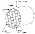
このようなハニカムフィルタは、通常、図1に示したハニカムフィルタ10のように、炭化珪素等からなる多孔質セラミック部材30が複数個結束されてセラミックブロック15を構成し、このセラミックブロック15の周囲にシール材層12が形成されている。また、この多孔質セラミック部材30は、図2に示したように、長手方向に多数の貫通孔31が並設され、貫通孔31同士を隔てる隔壁33がフィルタとして機能するようになっている。
【0004】
即ち、多孔質セラミック部材30に形成された貫通孔31は、図2(b)に示したように、排気ガスの入り口側又は出口側の端部のいずれかが充填材32により目封じされ、一の貫通孔31に流入した排気ガスは、必ず貫通孔31を隔てる隔壁33を通過した後、他の貫通孔31から流出されるようになっている。
【0005】
排気ガス浄化装置では、このような構成のハニカムフィルタ10が内燃機関の排気通路に設置され、内燃機関より排出された排気ガス中のパティキュレートは、このハニカムフィルタ10を通過する際に隔壁33により捕捉され、排気ガスが浄化される。
【0006】
このようなハニカムフィルタ10を製造する際には、まず、原料であるセラミック粒子の他に溶剤やバインダー等を含む混合組成物を調製し、この混合組成物を用いて押出成形等を行いセラミック成形体を作製する。そして、このセラミック成形体に乾燥、脱脂、焼成の各処理を施すことで多孔質セラミック部材30を製造する。
【0007】
次に、この多孔質セラミック部材30を接着層14となる接着剤ペーストを介して積層することによりセラミック積層体を組み上げ、乾燥後、所定形状に切削してセラミックブロック15を作製する。そして、このセラミックブロック15の外周部にシール材層13を形成することによりハニカムフィルタ10を製造していた。
【0008】
しかしながら、このような方法でハニカムフィルタ10を製造しようとすると、上記セラミック積層体の組み上げ工程において、多孔質セラミック部材30の側面に塗布した接着剤ペーストが多孔質セラミック部材30の端面部分にはみ出し、貫通孔31が形成されている部分に付着し、貫通孔31を塞いでしまうことがあった。
【0009】
また、同様の問題がシール材層13を形成する工程においても発生する場合があった。即ち、セラミックブロック15の外周部にシール材層13となるシール材ペーストを塗布し、シール材ペースト層を形成すると、上記シール材ペーストがセラミックブロック15の端面にはみ出して貫通孔31が形成されている部分に付着し、貫通孔31を塞いでしまうことがあった。
このように上記接着剤ペーストや上記シール材ペーストが、貫通孔31を塞いでしまうと、貫通孔31は目詰まりとなり、ハニカムフィルタのフィルタとしての機能が低下してしまう。
【0010】
そこで、多孔質セラミック部材30の両端面にガムテープやビニールテープを貼り付けて、このような貫通孔の目詰まりの防止図っていたが、このようなガムテープやビニールテープは、その耐熱性や耐久性に劣るものであったため、ハニカムフィルタ10の製造過程で、破損、分解、剥離等してしまうことがあった。
【0011】
【発明が解決しようとする課題】
本発明は、これらの問題を解決するためになされたもので、多孔質セラミック部材の両端面に貼り付けたマスキング材が、ハニカムフィルタの製造途中で容易に破損、分解、剥離してしまうことがないため、ハニカムフィルタの貫通孔にシール材等が侵入することなく、良好な特性を有するハニカムフィルタを製造する製造方法を提供することを目的とするものである。
【0012】
【課題を解決するための手段】
本発明は、多数の貫通孔が隔壁を隔てて長手方向に並設された角柱形状の多孔質セラミック部材が接着層を介して複数個結束されてセラミックブロックを構成するとともに、その外周部がシール材層によりコーティングされ、上記貫通孔を隔てる隔壁が粒子捕集用フィルタとして機能するように構成されたハニカムフィルタの製造方法であって、
上記多孔質セラミック部材を製造した後、その硬度が50〜150°、耐熱温度が120℃以上の基材フィルム上に粘着剤層が形成され、その粘着力が500〜2000gf/19mm幅のマスキング材を、上記多孔質セラミック部材の両端面に貼り付けるマスキング材貼り付け工程と、上記マスキング材を貼り付けた多孔質セラミック部材の側面に、接着剤ペーストを塗布し、上記接着剤ペーストの上に他の多孔質セラミック部材を積層する工程を繰り返して、セラミック積層体を組み上げ、上記セラミック積層体を加熱して上記接着剤ペーストを乾燥、硬化させるセラミック積層体作製工程と、上記セラミック積層体の一部を切削するとともに上記セラミック積層体の端面に接着された上記マスキング材を上記セラミック積層体が切削された部分の形状に切削して上記セラミックブロックを作製するセラミックブロック作製工程と、上記セラミックブロックの外周部にシール材層を形成してハニカムフィルタとするシール材層形成工程と、上記マスキング材の粘着力よりも強い粘着力を有する剥離用シートを上記ハニカムフィルタの端面に押し当て、上記剥離用シートに上記マスキング材を接着し、その後、上記剥離用シートを引き離すことにより、上記マスキング材を上記ハニカムフィルタの端面から剥離させるマスキング材剥離工程とを含むことを特徴とするハニカムフィルタの製造方法である。
以下、本発明のハニカムフィルタの製造方法について説明する。
【0013】
【発明の実施の形態】
本発明のハニカムフィルタの製造方法は、多数の貫通孔が隔壁を隔てて長手方向に並設された角柱形状の多孔質セラミック部材が接着層を介して複数個結束されてセラミックブロックを構成するとともに、その外周部がシール材層によりコーティングされ、上記貫通孔を隔てる隔壁が粒子捕集用フィルタとして機能するように構成されたハニカムフィルタの製造方法であって、
上記多孔質セラミック部材を製造した後、その硬度が50〜150°、耐熱温度が120℃以上の基材フィルム上に粘着剤層が形成され、その粘着力が500〜2000gf/19mm幅のマスキング材を、上記多孔質セラミック部材の両端面に貼り付けるマスキング材貼り付け工程と、上記マスキング材を貼り付けた多孔質セラミック部材の側面に、接着剤ペーストを塗布し、上記接着剤ペーストの上に他の多孔質セラミック部材を積層する工程を繰り返して、セラミック積層体を組み上げ、上記セラミック積層体を加熱して上記接着剤ペーストを乾燥、硬化させるセラミック積層体作製工程と、上記セラミック積層体の一部を切削するとともに上記セラミック積層体の端面に接着された上記マスキング材を上記セラミック積層体が切削された部分の形状に切削して上記セラミックブロックを作製するセラミックブロック作製工程と、上記セラミックブロックの外周部にシール材層を形成してハニカムフィルタとするシール材層形成工程と、上記マスキング材の粘着力よりも強い粘着力を有する剥離用シートを上記ハニカムフィルタの端面に押し当て、上記剥離用シートに上記マスキング材を接着し、その後、上記剥離用シートを引き離すことにより、上記マスキング材を上記ハニカムフィルタの端面から剥離させるマスキング材剥離工程とを含むことを特徴とするものである。
【0014】
本発明のハニカムフィルタの製造方法においては、まず、多孔質セラミック部材を製造するが、その製造方法については、上記従来の技術において説明した通りであるので、ここでは、その詳しい説明を省略する。
また、多孔質セラミック部材の原料であるセラミックは特に限定されず、種々のセラミックが挙げられるが、これらのなかでは、耐熱性が大きく、機械的特性に優れ、かつ、熱伝導率も大きい炭化珪素が好ましい。
【0015】
上記多孔質セラミック部材は、平均粒径が2〜150μmのセラミック結晶からなるものであることが望ましく、10〜70μmがより望ましい。上記セラミック結晶の平均粒径が2μm未満であると、多孔質セラミック部材の内部に存在する気孔の気孔径が小さくなりすぎ、直ぐに目詰まりを起こすため、フィルタとして機能することが困難となる。一方、上記セラミック結晶の平均粒径が150μmを超えると、その内部に存在する気孔の気孔径が大きくなりすぎ、多孔質セラミック部材の強度が低下してしまうおそれがある。また、所定の割合の開放気孔を有し、平均粒径が150μmを超えるようなセラミック結晶を有する多孔質セラミック部材を製造すること自体が余り容易でない。
【0016】
次に、上記製造した多孔質セラミック部材の両端面に、基材フィルム上に粘着剤層が形成されたマスキング材を貼り付ける。
【0017】
上記基材フィルムの硬度は50〜150°であるので、後述するセラミック積層体に切削加工を施す工程において、千切れたり、剥がれたり、伸び過ぎたりすることなく、切削された部分の形状にマスキング材も切断される。
上記硬度が50°未満であると、基材フィルムが柔らかすぎるため、セラミック積層体に切削加工を施した際、切削された部分と同様の形状に切断されず、マスキング材が伸び、後述するシール材層の形成工程の邪魔となったり、シールすべき部分のマスキング材が千切れて無くなってしまう等の不都合が生ずる。一方、上記硬度が150°を超えると、硬くなりすぎるため、多少の凹凸が形成された端面にしっかりと貼り付けることができず、剥がれやすくなる。
【0018】
また、上記基材フィルムの耐熱温度は120℃以上であるので、後述するシール材層の乾燥工程で変質したり、分解したりすることはない。
上記耐熱温度が120℃未満であると、後の乾燥工程等において、上記基材フィルムが分解してしまうおそれがある。上記耐熱温度は150℃以上であることが望ましい。
【0019】
上記粘着剤としては特に限定されず、例えば、ポリイソブチレン、SBR、ブチルゴム、クロロプレンゴム等のゴム系粘着剤、その他、アクリル系粘着剤等を挙げることができる。
【0020】
このような粘着剤を塗布した上記マスキング材の粘着力は、500〜2000gf/19mm幅であるため、後述する剥離シートを用いてマスキング材を剥離する工程で、容易に剥離することができ、かつ、ハニカムフィルタの製造途中で剥離することはない。上記粘着力が500gf/19mm幅未満であると、その粘着力が不充分であり、ハニカムフィルタの製造途中で上記マスキング材が剥離してしまうことがある。一方、上記粘着力が2000gf/19mm幅を超えると、後のマスキング材の剥離工程で、上記マスキング材を完全に剥離することが困難となる。上記粘着力は1000〜1500gf/19mm幅であることが望ましい。
【0021】
上記基材フィルムとしては、樹脂系フィルムであることが望ましい。耐熱性及び耐久性に優れ、上記各特性を略満たすことができるからである。
また、このような樹脂系フィルムのなかでは、ポリエステルフィルムであることが望ましく、特に、PETフィルムであることが望ましい。上述した各特性を満たすことができ、特に、耐熱性及び耐久性に優れるからである。
【0022】
このような基材フィルム及び粘着剤層からなるマスキング材の厚みは、10〜500μmであることが望ましい。厚みが10μm未満であると、その強度が低下して容易に破損してしまう。一方、厚みが500μmを超えると、硬度が高くなり取扱い性に劣り、また、上述したように、端面の形状に追従しにくくなるため、剥がれやすくなる。上記マスキング材の厚みは10〜100μmであることがより望ましい。
【0023】
上記多孔質セラミック部材の両端面に上記マスキング材を貼り付ける方法としては特に限定されず、例えば、予めマスキング材を多孔質セラミック部材の端面と同形状にカットしておき、機械アーム等を用いて自動的に貼り付けてもよく、手で張りつけてもよい。生産性を考慮すると機械アーム等を用いて自動的に貼り付ける方法が望ましい。
【0024】
次に、上記マスキング材を貼り付けた多孔質セラミック部材の側面に、接着剤ペーストを塗布し、上記接着剤ペーストの上に他の多孔質セラミック部材を積層する工程を繰り返して、セラミック積層体を組み上げるセラミック積層体作製工程を行う。
【0025】
このセラミック積層体作製工程においては、図3に示したように、断面がV字形状に構成された台60の上に、斜めに傾斜した状態で載置した多孔質セラミック部材30の上側を向いた2つの側面30a、30bに、上記接着剤ペーストを、例えば、刷毛、スキージ、ロール等を用いて印刷して、所定の厚さの接着剤ペースト層61を形成する。
【0026】
次に、この接着剤ペースト層61の上に他の多孔質セラミック部材30を積層する。そして、このような多孔質セラミック部材30の側面に接着剤ペースト層61を形成してから、他の多孔質セラミック部材30を積層する工程を繰り返して行い、所定の大きさの角柱状のセラミック積層体を作製する。
【0027】
上記接着剤ペーストとしては、耐熱性を有するものであれば特に限定されず、例えば、有機バインダー、無機バインダー、無機繊維及び無機粒子を含むものを挙げることができる。このような組成からなる接着剤ペーストは、多孔質セラミック部材との馴染みがよく接着強度に優れるとともに、熱伝導率にも優れたものとなる。
【0028】
上記有機バインダーとしては、例えば、ポリビニルアルコール、メチルセルロース、エチルセルロース、カルボキシセルロース等が挙げられる。これらは、単独で用いてもよく、2種以上を併用してもよい。上記有機バインダーのなかでは、カルボキシセルロースが好ましい。
【0029】
上記無機バインダーとしては、例えば、シリカゾル、アルミナゾル等が挙げられる。これらは、単独で用いてもよく、2種以上を併用してもよい。上記無機バインダーのなかでは、シリカゾルが好ましい。
【0030】
上記無機繊維としては、例えば、シリカーアルミナ、ムライト、アルミナ、シリカ等のセラミックファイバー等が挙げられる。これらは、単独で用いてもよく、2種以上を併用してもよい。上記無機繊維のなかでは、シリカーアルミナファイバーが好ましい。
【0031】
上記無機粒子としては、例えば、炭化物、窒化物等が挙げられ、具体的には、炭化珪素、窒化珪素、窒化硼素等からなる無機粉末又はウィスカー等が挙げられる。これらは、単独で用いてもよく、2種以上を併用してもよい。上記無機粒子のなかでは、熱伝導性に優れる炭化珪素が好ましい。
【0032】
この接着剤ペースト中には、接着剤ペースト層を柔軟にし、流動性を付与して塗布しやすくするため、上記した有機バインダー、無機バインダー、無機繊維及び無機粒子のほかに、およそ総重量の35〜65重量%程度の水分や他のアセトン、アルコール等の溶剤等が含まれている。この接着剤ペーストの粘度は、15〜25Pa・s(1万〜2万cps(cP))が好ましい。
【0033】
この接着剤ペーストを、多孔質セラミック部材の側面に付着させる方法としては特に限定されず、例えば、接着剤ペーストをチューブ等を用いて輸送し、接着剤ペーストの塊を上記チューブより流出させて、多孔質セラミック部材の側面に付着させる方法等が挙げられる。
【0034】
次に、このようにして作製したセラミック積層体を、例えば、50〜150℃、1時間の条件で加熱して上記接着剤ペースト層を乾燥、硬化させ、接着層とした後、上記セラミック積層体の一部を切削し、上記セラミックブロックを作製するセラミックブロック作製工程を行う。
【0035】
上記セラミック積層体の一部を切削する方法としては特に限定されず、例えば、ダイヤモンドカッター等を用いて、上記セラミック積層体の外周部を切削する方法等を挙げることができる。
このとき、上記セラミック積層体の端面に接着されたマスキング材は、上述した特性を有するので、切削部分のマスキング材が伸びたり、千切れたり、剥がれたりすることなく、切削部分と同様の形状に切削される。従って、後述するシール材層の形成工程で、シール材ペーストが多孔質セラミック部材の貫通孔に浸入するのを防止することができる。
【0036】
次に、このようにして作製したセラミックブロックの外周部にシール材ペーストを塗布し、乾燥させ、シール材層を形成し、ハニカムフィルタを作製する。
【0037】
上記シール材ペーストとしては特に限定されず、例えば、上記接着剤ペーストと同様の組成からなるペーストを挙げることができる。
【0038】
また、上記シール材層を形成する方法としては特に限定されず、例えば、上記セラミックブロックをその回転軸方向に軸支、回転させ、上記接着層を形成した場合と同様に、チューブ等を用いて、上記シール材ペーストの塊を、回転しているセラミックブロックの外周部に付着させる。そして、板状部材等を用いてシール材ペーストを引き延ばし、シール材ペースト層を形成する方法を挙げることができる。
このとき、シール材ペーストが端面に付着する場合があるが、本発明では、端面にマスキング材が貼り付けられているため、シール材ペーストが多孔質セラミック部材の貫通孔に侵入することはない。
この後、例えば、120℃以上の温度で乾燥させることにより、水分を蒸発させてシール材層とするが、本発明で用いたマスキング材は、120℃以上の耐熱性を有するので、この乾燥工程で柔らかくなりすぎ、縮んだり、分解したりすることはない。
【0039】
次に、このようにして作製したハニカムフィルタの両端面に貼り付けられている上記マスキング材を剥離するマスキング材剥離工程を行うことにより、本発明のハニカムフィルタの製造方法を終了する。
【0040】
上記マスキング材を剥離する方法としては特に限定されず、例えば、上記マスキング材の粘着力よりも強い粘着力を有する粘着剤を塗布した剥離用シートを、上記ハニカムフィルタの端面に押し当て、上記剥離用シートに上記マスキング材を接着し、その後、上記剥離用シートを引き離すことにより、複数の上記マスキング材を上記ハニカムフィルタの端面から剥離させる方法や、へらやカッター等を用いて手作業で剥離する方法等を挙げることができるが、剥離用シートを用いる方法が好ましい。
【0041】
上記マスキング材の粘着力よりも強い粘着力を有する粘着剤を塗布した剥離用シートとしては、例えば、ポリエステルフィルムにゴム系粘着剤を塗布したもの等を挙げることができる。
【0042】
上記剥離用シートの粘着力は、3000〜8000g/25mm幅であることが望ましい。粘着力が3000g/25mm幅未満であると、粘着力が不充分であり、マスキング材をハニカムフィルタの端面から完全に剥離することができない場合がある。一方、粘着力が8000g/25mm幅を超えると、粘着力が強すぎるため、取り扱い性に劣り、また、マスキング材を剥離するのに充分な粘着力を有するものであり、これ以上の粘着力を有する剥離用シートは、製造コストの高騰を招く。なお、上述した粘着力を有する上記マスキング材は、ハニカムフィルタの製造途中の熱や外的要因によって容易に剥離することはないが、上記マスキング材よりも強い粘着力を有する上記剥離用シートにより容易にハニカムフィルタの端面から剥離することができる。
【0043】
また、上記剥離用シートの形状は、ハニカムフィルタの端面と略同形状、矩形状等任意の形状のものを挙げることができるが、そのサイズとしては、ハニカムフィルタの端面を完全に覆うことができるものであることが望ましい。ハニカムフィルタの端面の略全面に貼り付けたマスキング材を完全に接着することができるからである。
【0044】
このような剥離用シートをハニカムフィルタの端面に押し当てる方法としては特に限定されず、任意の方法で押し当てることができるが、ローラをハニカムフィルタの端面に沿って転がす方法が望ましい。ローラとハニカムフィルタの端面とが成す角度は常に一定であるので、均一な押圧力で剥離用シートをハニカムフィルタの端面に押し当てることができるからである。
【0045】
上記ローラの直径は、押し当てる対象であるハニカムフィルタの端面の直径に合わせて適宜調整されるが、50〜200mm程度であることが望ましい。直径が50mm未満であると、ローラをハニカムフィルタの端面の一端部から中心を挟んだ他端部まで転がすのに時間がかかり、生産性の低下を招く。一方、直径が200mmを超えると、均一な押圧で剥離用シートをハニカムフィルタの端面に押し当てることが困難となる。
【0046】
また、上記ローラの幅は特に限定されず、ハニカムフィルタの端面の直径よりも少し大きくなるように調整されることが望ましい。上記ローラをハニカムフィルタの端面に沿って転がす回数を一度だけにすることができるからである。
【0047】
また、少なくとも上記ローラの表面は、40〜90°の硬度を有する弾性体であることが望ましい。上記ローラを用いて剥離用シートをハニカムフィルタの端面に押し当てた際、剥離用シート、マスキング材及びハニカムフィルタの端面の破損を防止するためである。
【0048】
上記弾性体は、上記ローラの表面から少なくとも5mmの厚さで形成されていることが望ましい。弾性体の厚さが5mm未満であると、ローラをハニカムフィルタの端面に押し当てた際、上記弾性体が変形し、ローラの弾性体非形成部分にまで押圧がかかり、剥離用シート、マスキング材及びハニカムフィルタの端面が破損するおそれがある。
なお、「少なくとも」であるから、上記ローラの全体が上記弾性体からなるものであってもよい。
【0049】
上記弾性体としては、ウレタン系発泡ゴム又はクロロプレン系スポンジゴムであることが望ましい。適度な硬度を有するものであり、剥離用シートをハニカムフィルタの端面に押し当てた際、ハニカムフィルタの端面と接触している部分が適度に変形し、剥離用シートと接着シートとを確実に貼り付けることができるからである。
【0050】
また、上記弾性体としては、ネオプレンスポンジゴムであることが最も望ましい。50°と好適な硬度を有し、ハニカムフィルタの端面に押し当てた際、剥離用シート、マスキング材及びハニカムフィルタの端面を傷つけることがなく、また、ハニカムフィルタの端面と接触する上記ネオプレンスポンジゴムが適度に変形し、確実にマスキング材全体を剥離用シートに貼り付けることができるからである。また、その加工性にも優れる。
【0051】
その他の弾性体の例としては、例えば、スチレン・ブタジエンゴム、ブタジエンゴム、イソプレンゴム、クロロプレンゴム、ウレタンゴム、シリコーンゴム等の合成ゴムやポリイソブチレン、ポリエチレン等のエラストマー、発泡ポリウレタン、発泡ポリスチレン、発泡ポリエチレン、発泡ポリプロピレン等のプラスチック発泡体、その他、天然ゴム、スポンジゴム等を挙げることができる。
【0052】
以上説明した通り、本発明のハニカムフィルタの製造方法は、製造した多孔質セラミック部材の両端面に、耐熱性及び耐久性に優れたマスキング材を貼り付けているため、貼り付けたマスキング材が、ハニカムフィルタの製造途中で容易に破損、分解、剥離してしまうことがなく、その結果、ハニカムフィルタの貫通孔にシール材等が侵入することなく、良好な特性を有するハニカムフィルタを製造することができる。
【0053】
【実施例】
以下に実施例を掲げて本発明を更に詳しく説明するが、本発明はこれら実施例のみに限定されるものではない。
【0054】
実施例1
炭化珪素粉末に有機バインダー、水等を加えて混練した後、押し出し成形を行い、ハニカム形状の生成形体を作製し、続いて、乾燥、脱脂、焼成を行うことにより、図2に示したような平均気孔径が1〜40μmで、セル数が31個/cm2 で、隔壁の厚さが0.3mmの多孔質セラミック部材を製造した。
【0055】
次に、上記多孔質セラミック部材の両端面に、粘着剤として熱硬化性ゴム系粘着剤を塗布したPETフィルムからなるマスキング材(日東電工社製:No.315)を貼り付けた。
なお、上記マスキング材は、硬度が110°、耐熱温度が150℃、粘着力が1200g/19mm幅であった。
【0056】
次に、上記多孔質セラミック部材を、無機繊維や無機粒子等を含む耐熱性の接着剤を用いて多数結束させてセラミック積層体を作製し、続いて、ダイヤモンドカッターを用いて切削してセラミックブロックを作製した後、上記接着剤と同じ成分からなるシール材をその外周部に形成し、130℃で乾燥することにより、図1に示したような円柱形状のハニカムフィルタを製造した。
【0057】
そして、剥離用シートとして、ゴム系粘着剤を塗布したポリエステルフィルム(スコッチ社製:No.859)を上記ハニカムフィルタの端面に押し当てて、上記マスキング材を上記剥離用シートに接着し、上記剥離用シートをハニカムフィルタの端面から引き離すことで、上記マスキング材をハニカムフィルタの端面から剥離させた。
なお、この剥離用シートの粘着力は5000gf/25mm幅であり、該剥離用シートをハニカムフィルタの端面に押し当てる際、その表面にネオプレンゴムが形成されたローラを使用した。
【0058】
本実施例1において、多孔質セラミック部材に貼り付けたマスキング材は、上記セラミックブロック作製工程でも、千切れたり、伸びたり、剥離したりすることなく、切削した形状と同様の形状に切削された。また、乾燥工程においても、変質や分解することはなかった。さらに、剥離シートにより、剥離工程でも、容易に剥離された。良好な特性を有するハニカムフィルタを製造することができた。また、製造したハニカムフィルタの端面の状態を目視にて観察したところ、特に目詰まりが発生している貫通孔はなかった。
【0059】
比較例1
多孔質セラミック部材の両端面に貼り付けるマスキング材を、市販されているガムテープとした他は、実施例1と同様にしてハニカムフィルタを製造した。
【0060】
本比較例1において、上記マスキング材として多孔質セラミック部材の両端面に貼り付けたガムテープは、ハニカムフィルタの製造の途中において、一部に破損及び剥離が見られ、上記多孔質セラミック部材の端面を完全に覆うことができなかった。また、製造したハニカムフィルタの端面の状態を目視にて観察したところ、ハニカムフィルタの貫通孔の一部に接着剤ペースト及びシール剤ペーストが侵入し、目詰まりをおこしている部分があり、本比較例1に係るハニカムフィルタは、フィルタとしての機能に劣るものであった。
【0061】
【発明の効果】
本発明のハニカムフィルタの製造方法は、上述の通りであり、マスキング材は、耐熱性に優れるとともに、適度な硬度や粘着性を有するので、ハニカムフィルタの端面部分に貼り付けられたマスキング材が、ハニカムフィルタの製造途中で、一部が剥離したり、破損したり、分解や変質が発生しない。従って、ハニカムフィルタの貫通孔が目詰まりをおこすことがなく、良好にハニカムフィルタを製造することができる。
【図面の簡単な説明】
【図1】ハニカムフィルタの一実施形態を模式的に示した斜視図である。
【図2】(a)は、ハニカムフィルタを構成する多孔質セラミック部材を模式的に示した斜視図であり、(b)は、そのA−A線断面図である。
【図3】セラミックブロックを作製する様子を模式的に示した説明図である。
【符号の説明】
10 ハニカムフィルタ
13 シール材層
14 接着層
15 セラミックブロック
30 多孔質セラミック部材
30a、30b 側面
31 貫通孔
32 充填材
33 隔壁
60 台
61 接着剤ペースト層[0001]
BACKGROUND OF THE INVENTION
The present invention relates to a method for manufacturing a honeycomb filter used as a filter for removing particulates and the like in exhaust gas discharged from an internal combustion engine.
[0002]
[Prior art]
Recently, it has become a problem that particulates contained in exhaust gas discharged from internal combustion engines such as automobiles, buses, trucks and the like and construction machines cause harm to the environment and the human body.
Various honeycomb filters that purify exhaust gas by collecting particulates in exhaust gas by passing the exhaust gas through a porous ceramic have been proposed.
[0003]
Such a honeycomb filter usually has a ceramic block 15 formed by binding a plurality of porous
[0004]
That is, in the
[0005]
In the exhaust gas purification apparatus, the honeycomb filter 10 having such a configuration is installed in the exhaust passage of the internal combustion engine, and particulates in the exhaust gas discharged from the internal combustion engine are separated by the
[0006]
When manufacturing such a honeycomb filter 10, first, a mixed composition containing a solvent, a binder and the like in addition to the ceramic particles as a raw material is prepared, and extrusion molding or the like is performed using this mixed composition to form a ceramic. Create a body. And the porous
[0007]
Next, the ceramic laminate 15 is assembled by laminating the porous
[0008]
However, when the honeycomb filter 10 is manufactured by such a method, the adhesive paste applied to the side surface of the porous
[0009]
In addition, the same problem may occur in the process of forming the sealing material layer 13. That is, when the sealing material paste that becomes the sealing material layer 13 is applied to the outer peripheral portion of the ceramic block 15 to form the sealing material paste layer, the sealing material paste protrudes from the end face of the ceramic block 15 to form the through
As described above, when the adhesive paste or the sealing material paste blocks the through
[0010]
Then, the adhesive tape was stuck on the both end surfaces of the porous
[0011]
[Problems to be solved by the invention]
The present invention was made to solve these problems, and the masking material attached to both end faces of the porous ceramic member may be easily damaged, decomposed, or peeled off during the manufacture of the honeycomb filter. Therefore, an object of the present invention is to provide a manufacturing method for manufacturing a honeycomb filter having good characteristics without a sealing material or the like entering a through hole of the honeycomb filter.
[0012]
[Means for Solving the Problems]
In the present invention, a plurality of prismatic porous ceramic members each having a large number of through holes arranged in parallel in the longitudinal direction with a partition wall therebetween are bound together via an adhesive layer to constitute a ceramic block, and the outer periphery thereof is sealed. A method for manufacturing a honeycomb filter coated with a material layer and configured so that a partition wall separating the through holes functions as a particle collecting filter,
After producing the porous ceramic member, a masking material having an adhesive layer formed on a base film having a hardness of 50 to 150 ° and a heat-resistant temperature of 120 ° C. or more, and an adhesive force of 500 to 2000 gf / 19 mm width. A masking material affixing step for adhering to both end faces of the porous ceramic member, and applying an adhesive paste to the side surface of the porous ceramic member affixing the masking material, Assembling the ceramic laminate by repeating the process of laminating porous ceramic members The ceramic laminate is heated to dry and cure the adhesive paste. Ceramic laminate manufacturing process and cutting part of the ceramic laminate And cutting the masking material bonded to the end face of the ceramic laminate into the shape of the cut portion of the ceramic laminate. A ceramic block manufacturing process for manufacturing the ceramic block and a sealing material layer formed on the outer periphery of the ceramic block A sealing material layer forming step to form a honeycomb filter, and a release sheet having an adhesive strength stronger than the adhesive strength of the masking material is pressed against the end face of the honeycomb filter, and the masking material is adhered to the release sheet. Then, the masking material is peeled off from the end face of the honeycomb filter by pulling off the peeling sheet. It is a manufacturing method of the honey-comb filter characterized by including a masking material peeling process.
Hereinafter, the manufacturing method of the honeycomb filter of the present invention will be described.
[0013]
DETAILED DESCRIPTION OF THE INVENTION
The method for manufacturing a honeycomb filter according to the present invention includes a plurality of prismatic porous ceramic members each having a plurality of through-holes arranged in parallel in the longitudinal direction with a partition wall interposed therebetween to form a ceramic block through an adhesive layer. A honeycomb filter manufacturing method in which the outer peripheral portion is coated with a sealing material layer, and the partition walls separating the through holes function as a filter for collecting particles,
After producing the porous ceramic member, a masking material having an adhesive layer formed on a base film having a hardness of 50 to 150 ° and a heat-resistant temperature of 120 ° C. or more, and an adhesive force of 500 to 2000 gf / 19 mm width. A masking material affixing step for adhering to both end faces of the porous ceramic member, and applying an adhesive paste to the side surface of the porous ceramic member affixing the masking material, Assembling the ceramic laminate by repeating the process of laminating porous ceramic members The ceramic laminate is heated to dry and cure the adhesive paste. Ceramic laminate manufacturing process and cutting part of the ceramic laminate And cutting the masking material bonded to the end face of the ceramic laminate into the shape of the cut portion of the ceramic laminate. A ceramic block manufacturing process for manufacturing the ceramic block and a sealing material layer formed on the outer periphery of the ceramic block A sealing material layer forming step to form a honeycomb filter, and a release sheet having an adhesive strength stronger than the adhesive strength of the masking material is pressed against the end face of the honeycomb filter, and the masking material is adhered to the release sheet. Then, the masking material is peeled off from the end face of the honeycomb filter by pulling off the peeling sheet. And a masking material peeling step.
[0014]
In the method for manufacturing a honeycomb filter of the present invention, first, a porous ceramic member is manufactured. Since the manufacturing method is as described in the prior art, a detailed description thereof is omitted here.
In addition, the ceramic that is a raw material of the porous ceramic member is not particularly limited and includes various ceramics. Among these, silicon carbide having high heat resistance, excellent mechanical properties, and high thermal conductivity. Is preferred.
[0015]
The porous ceramic member is preferably made of ceramic crystals having an average particle diameter of 2 to 150 μm, more preferably 10 to 70 μm. When the average particle size of the ceramic crystal is less than 2 μm, the pore diameter of the pores present in the porous ceramic member becomes too small and immediately clogs, making it difficult to function as a filter. On the other hand, if the average particle diameter of the ceramic crystal exceeds 150 μm, the pore diameter of the pores present in the ceramic crystal becomes too large, and the strength of the porous ceramic member may be reduced. Moreover, it is not so easy to manufacture a porous ceramic member having ceramic crystals having a predetermined ratio of open pores and an average particle size exceeding 150 μm.
[0016]
Next, the masking material in which the adhesive layer was formed on the base film is affixed on the both end surfaces of the produced porous ceramic member.
[0017]
Since the hardness of the base film is 50 to 150 °, it is masked to the shape of the cut portion without being torn off, peeled off or stretched excessively in the step of cutting the ceramic laminate described later. The material is also cut.
When the hardness is less than 50 °, the base film is too soft, so when the ceramic laminate is cut, it is not cut into the same shape as the cut portion, the masking material is stretched, and a seal described later Inconveniences such as obstructing the material layer forming process and the masking material at the portion to be sealed being cut off are lost. On the other hand, when the hardness exceeds 150 °, it becomes too hard, so that it cannot be firmly attached to the end face on which some unevenness is formed, and is easily peeled off.
[0018]
Moreover, since the heat-resistant temperature of the said base film is 120 degreeC or more, it does not deteriorate or decompose | disassemble by the drying process of the sealing material layer mentioned later.
There exists a possibility that the said base film may decompose | disassemble in the subsequent drying process etc. as the said heat-resistant temperature is less than 120 degreeC. The heat-resistant temperature is desirably 150 ° C. or higher.
[0019]
The pressure-sensitive adhesive is not particularly limited, and examples thereof include rubber pressure-sensitive adhesives such as polyisobutylene, SBR, butyl rubber, and chloroprene rubber, and other acrylic pressure-sensitive adhesives.
[0020]
Since the adhesive strength of the masking material coated with such an adhesive is 500 to 2000 gf / 19 mm width, it can be easily peeled off in the step of peeling the masking material using a release sheet described later, and No peeling occurs during the manufacture of the honeycomb filter. If the adhesive strength is less than 500 gf / 19 mm width, the adhesive strength is insufficient, and the masking material may peel off during the manufacture of the honeycomb filter. On the other hand, when the adhesive strength exceeds 2000 gf / 19 mm width, it is difficult to completely remove the masking material in a subsequent masking material peeling step. The adhesive strength is desirably 1000 to 1500 gf / 19 mm width.
[0021]
The base film is preferably a resin film. It is because it is excellent in heat resistance and durability and can substantially satisfy each of the above characteristics.
Among such resin-based films, a polyester film is desirable, and a PET film is particularly desirable. This is because the above-described characteristics can be satisfied, and in particular, heat resistance and durability are excellent.
[0022]
As for the thickness of the masking material which consists of such a base film and an adhesive layer, it is desirable that it is 10-500 micrometers. If the thickness is less than 10 μm, the strength is reduced and the film is easily damaged. On the other hand, when the thickness exceeds 500 μm, the hardness becomes high and the handleability is inferior. Further, as described above, it becomes difficult to follow the shape of the end face, so that it is easy to peel off. The thickness of the masking material is more preferably 10 to 100 μm.
[0023]
The method for attaching the masking material to both end faces of the porous ceramic member is not particularly limited. For example, the masking material is cut in the same shape as the end face of the porous ceramic member in advance, and a mechanical arm or the like is used. You can paste it automatically or you can stick it by hand. In view of productivity, a method of automatically attaching using a mechanical arm or the like is desirable.
[0024]
Next, an adhesive paste is applied to the side surface of the porous ceramic member to which the masking material is pasted, and the process of laminating another porous ceramic member on the adhesive paste is repeated to obtain a ceramic laminate. The ceramic laminated body production process to assemble is performed.
[0025]
In this ceramic laminate manufacturing process, as shown in FIG. 3, the upper side of the porous
[0026]
Next, another porous
[0027]
The adhesive paste is not particularly limited as long as it has heat resistance, and examples thereof include an organic binder, an inorganic binder, inorganic fibers, and inorganic particles. The adhesive paste having such a composition is well-familiar with the porous ceramic member and excellent in adhesive strength, and also excellent in thermal conductivity.
[0028]
Examples of the organic binder include polyvinyl alcohol, methyl cellulose, ethyl cellulose, carboxy cellulose, and the like. These may be used alone or in combination of two or more. Among the organic binders, carboxycellulose is preferable.
[0029]
Examples of the inorganic binder include silica sol and alumina sol. These may be used alone or in combination of two or more. Among the inorganic binders, silica sol is preferable.
[0030]
Examples of the inorganic fibers include ceramic fibers such as silica-alumina, mullite, alumina, and silica. These may be used alone or in combination of two or more. Of the inorganic fibers, silica-alumina fibers are preferred.
[0031]
Examples of the inorganic particles include carbides and nitrides, and specific examples include inorganic powders or whiskers made of silicon carbide, silicon nitride, boron nitride, or the like. These may be used alone or in combination of two or more. Of the inorganic particles, silicon carbide having excellent thermal conductivity is preferable.
[0032]
In this adhesive paste, in order to soften the adhesive paste layer and impart fluidity to facilitate application, in addition to the organic binder, inorganic binder, inorganic fiber and inorganic particles described above, approximately 35% of the total weight. About 65% by weight of water and other solvents such as acetone and alcohol are contained. The viscosity of the adhesive paste is preferably 15 to 25 Pa · s (10,000 to 20,000 cps (cP)).
[0033]
The adhesive paste is not particularly limited as a method for adhering to the side surface of the porous ceramic member, for example, the adhesive paste is transported using a tube or the like, the lump of the adhesive paste is allowed to flow out of the tube, Examples include a method of adhering to the side surface of the porous ceramic member.
[0034]
Next, the ceramic laminate thus produced is heated, for example, at 50 to 150 ° C. for 1 hour to dry and cure the adhesive paste layer to obtain an adhesive layer, and then the ceramic laminate. The ceramic block preparation process which cuts one part and produces the said ceramic block is performed.
[0035]
The method for cutting a part of the ceramic laminate is not particularly limited, and examples thereof include a method for cutting the outer peripheral portion of the ceramic laminate using a diamond cutter or the like.
At this time, the ceramic laminate End face Since the masking material adhered to has the above-described characteristics, the masking material at the cutting portion is cut into the same shape as the cutting portion without stretching, breaking or peeling off. Therefore, it is possible to prevent the sealing material paste from entering the through-holes of the porous ceramic member in the sealing material layer forming step described later.
[0036]
Next, a sealing material paste is applied to the outer peripheral portion of the ceramic block thus manufactured and dried to form a sealing material layer, thereby manufacturing a honeycomb filter.
[0037]
It does not specifically limit as said sealing material paste, For example, the paste which consists of a composition similar to the said adhesive paste can be mentioned.
[0038]
Further, the method for forming the sealing material layer is not particularly limited. For example, the ceramic block is pivotally supported and rotated in the direction of the rotation axis, and a tube or the like is used similarly to the case where the adhesive layer is formed. The lump of the sealing material paste is attached to the outer peripheral portion of the rotating ceramic block. And the method of extending a sealing material paste using a plate-shaped member etc. and forming a sealing material paste layer can be mentioned.
At this time, the sealing material paste may adhere to the end face, but in the present invention, since the masking material is attached to the end face, the sealing material paste does not enter the through hole of the porous ceramic member.
Thereafter, for example, by drying at a temperature of 120 ° C. or higher, moisture is evaporated to form a sealing material layer. However, the masking material used in the present invention has a heat resistance of 120 ° C. or higher, so this drying step It will be too soft and will not shrink or decompose.
[0039]
Next, the manufacturing method of the honeycomb filter of the present invention is completed by performing a masking material peeling step for peeling off the masking material attached to both end faces of the honeycomb filter thus manufactured.
[0040]
The method for peeling the masking material is not particularly limited. For example, a peeling sheet coated with an adhesive having an adhesive strength stronger than the adhesive strength of the masking material is pressed against the end face of the honeycomb filter, and the peeling is performed. The above masking material is adhered to the sheet for use, and then the peeling sheet is pulled away so that the plurality of masking materials are peeled off from the end face of the honeycomb filter, or manually peeled off using a spatula or a cutter. Although a method etc. can be mentioned, The method using a peeling sheet is preferable.
[0041]
As a peeling sheet which apply | coated the adhesive which has an adhesive strength stronger than the adhesive force of the said masking material, what apply | coated the rubber-type adhesive to the polyester film etc. can be mentioned, for example.
[0042]
The adhesive strength of the release sheet is desirably 3000 to 8000 g / 25 mm width. When the adhesive strength is less than 3000 g / 25 mm width, the adhesive strength is insufficient, and the masking material may not be completely peeled from the end face of the honeycomb filter. On the other hand, when the adhesive strength exceeds 8000 g / 25 mm width, the adhesive strength is too strong, so that the handleability is inferior, and the adhesive strength is sufficient to peel off the masking material. The peeling sheet that is included causes an increase in manufacturing costs. Note that the above-mentioned masking material having the above-mentioned adhesive strength is not easily peeled off due to heat or external factors during the manufacture of the honeycomb filter, but is easier to use with the above-mentioned peeling sheet having a stronger adhesive strength than the above-mentioned masking material. Further, it can be peeled from the end face of the honeycomb filter.
[0043]
In addition, the shape of the release sheet may include any shape such as substantially the same shape as the end face of the honeycomb filter, a rectangular shape, and the size of the release sheet can completely cover the end face of the honeycomb filter. It is desirable to be a thing. This is because the masking material affixed to substantially the entire end face of the honeycomb filter can be completely bonded.
[0044]
The method for pressing such a release sheet against the end face of the honeycomb filter is not particularly limited, and can be pressed by any method, but a method of rolling a roller along the end face of the honeycomb filter is desirable. This is because the angle formed between the roller and the end face of the honeycomb filter is always constant, so that the release sheet can be pressed against the end face of the honeycomb filter with a uniform pressing force.
[0045]
The diameter of the roller is appropriately adjusted according to the diameter of the end face of the honeycomb filter to be pressed, and is preferably about 50 to 200 mm. If the diameter is less than 50 mm, it takes time to roll the roller from one end portion of the end face of the honeycomb filter to the other end portion with the center interposed therebetween, resulting in a decrease in productivity. On the other hand, when the diameter exceeds 200 mm, it becomes difficult to press the release sheet against the end face of the honeycomb filter with uniform pressing.
[0046]
The width of the roller is not particularly limited, and is preferably adjusted to be slightly larger than the diameter of the end face of the honeycomb filter. This is because the roller can be rolled only once along the end face of the honeycomb filter.
[0047]
Further, it is desirable that at least the surface of the roller is an elastic body having a hardness of 40 to 90 °. This is because when the release sheet is pressed against the end face of the honeycomb filter using the roller, damage to the end face of the release sheet, the masking material, and the honeycomb filter is prevented.
[0048]
The elastic body is preferably formed with a thickness of at least 5 mm from the surface of the roller. When the elastic body has a thickness of less than 5 mm, when the roller is pressed against the end face of the honeycomb filter, the elastic body is deformed and the elastic body non-forming portion of the roller is pressed, and the release sheet and the masking material In addition, the end face of the honeycomb filter may be damaged.
In addition, since it is “at least”, the entire roller may be made of the elastic body.
[0049]
The elastic body is preferably urethane foam rubber or chloroprene sponge rubber. It has an appropriate hardness, and when the release sheet is pressed against the end face of the honeycomb filter, the portion in contact with the end face of the honeycomb filter is deformed appropriately, and the release sheet and the adhesive sheet are securely attached. Because it can be attached.
[0050]
The elastic body is most preferably neoprene sponge rubber. The neoprene sponge rubber which has a suitable hardness of 50 ° and does not damage the peeling sheet, the masking material and the end face of the honeycomb filter when pressed against the end face of the honeycomb filter, and is in contact with the end face of the honeycomb filter This is because the material can be appropriately deformed and the entire masking material can be reliably attached to the release sheet. Moreover, the processability is also excellent.
[0051]
Examples of other elastic bodies include, for example, synthetic rubbers such as styrene / butadiene rubber, butadiene rubber, isoprene rubber, chloroprene rubber, urethane rubber and silicone rubber, elastomers such as polyisobutylene and polyethylene, polyurethane foam, polystyrene foam, and foam. Examples thereof include plastic foams such as polyethylene and expanded polypropylene, natural rubber, sponge rubber and the like.
[0052]
As explained above, since the manufacturing method of the honeycomb filter of the present invention has a masking material excellent in heat resistance and durability attached to both end faces of the manufactured porous ceramic member, the attached masking material is A honeycomb filter having good characteristics can be manufactured without being easily broken, disassembled, or peeled off during the manufacture of the honeycomb filter, and as a result, a sealing material or the like does not enter the through hole of the honeycomb filter. it can.
[0053]
【Example】
Hereinafter, the present invention will be described in more detail with reference to examples. However, the present invention is not limited to these examples.
[0054]
Example 1
After adding and kneading an organic binder, water, etc. to silicon carbide powder, extrusion molding is performed to produce a honeycomb-shaped product, followed by drying, degreasing and firing, as shown in FIG. The average pore size is 1-40 μm, and the number of cells is 31 / cm 2 Thus, a porous ceramic member having a partition wall thickness of 0.3 mm was manufactured.
[0055]
Next, a masking material (manufactured by Nitto Denko Corporation: No. 315) made of a PET film coated with a thermosetting rubber adhesive as an adhesive was attached to both end faces of the porous ceramic member.
The masking material had a hardness of 110 °, a heat resistant temperature of 150 ° C., and an adhesive strength of 1200 g / 19 mm width.
[0056]
Next, a ceramic laminate is produced by binding a number of the porous ceramic members using a heat-resistant adhesive containing inorganic fibers, inorganic particles, etc., and then cutting with a diamond cutter to make a ceramic block Then, a sealing material made of the same component as the above adhesive was formed on the outer periphery thereof, and dried at 130 ° C. to produce a cylindrical honeycomb filter as shown in FIG.
[0057]
Then, as a release sheet, a polyester film coated with a rubber adhesive (manufactured by Scotch: No. 859) is pressed against the end face of the honeycomb filter, the masking material is adhered to the release sheet, and the release sheet is removed. The masking material was peeled off from the end face of the honeycomb filter by pulling the sheet for use away from the end face of the honeycomb filter.
The adhesive strength of the release sheet was 5000 gf / 25 mm width, and when the release sheet was pressed against the end face of the honeycomb filter, a roller having neoprene rubber formed on the surface thereof was used.
[0058]
In this Example 1, the masking material affixed to the porous ceramic member was cut into the same shape as the cut shape without being torn, stretched, or peeled even in the ceramic block manufacturing process. . In the drying process, neither alteration nor decomposition occurred. Furthermore, it was easily peeled off by the release sheet even in the peeling step. A honeycomb filter having good characteristics could be manufactured. Further, when the state of the end face of the manufactured honeycomb filter was visually observed, there was no through-hole in which clogging occurred in particular.
[0059]
Comparative Example 1
A honeycomb filter was produced in the same manner as in Example 1 except that a commercially available gum tape was used as the masking material to be attached to both end faces of the porous ceramic member.
[0060]
In this Comparative Example 1, the gummed tape affixed to both end faces of the porous ceramic member as the masking material was partially damaged and peeled off during the manufacture of the honeycomb filter, and the end face of the porous ceramic member was Could not be completely covered. In addition, when the state of the end face of the manufactured honeycomb filter was visually observed, the adhesive paste and the sealant paste penetrated into a part of the through hole of the honeycomb filter, and there was a clogged portion. The honeycomb filter according to Example 1 was inferior in function as a filter.
[0061]
【The invention's effect】
The manufacturing method of the honeycomb filter of the present invention is as described above, and the masking material is excellent in heat resistance and has appropriate hardness and adhesiveness. Therefore, the masking material attached to the end face portion of the honeycomb filter is, During the manufacture of the honeycomb filter, a part of the honeycomb filter is not peeled off or damaged, and no decomposition or alteration occurs. Therefore, the through hole of the honeycomb filter is not clogged, and the honeycomb filter can be manufactured satisfactorily.
[Brief description of the drawings]
FIG. 1 is a perspective view schematically showing an embodiment of a honeycomb filter.
FIG. 2 (a) is a perspective view schematically showing a porous ceramic member constituting a honeycomb filter, and FIG. 2 (b) is a cross-sectional view taken along line AA.
FIG. 3 is an explanatory view schematically showing how a ceramic block is manufactured.
[Explanation of symbols]
10 Honeycomb filter
13 Sealing material layer
14 Adhesive layer
15 Ceramic block
30 Porous ceramic member
30a, 30b side
31 Through hole
32 Filler
33 Bulkhead
60 units
61 Adhesive paste layer
Claims (12)
Priority Applications (1)
| Application Number | Priority Date | Filing Date | Title |
|---|---|---|---|
| JP2000332364A JP4357110B2 (en) | 2000-10-31 | 2000-10-31 | Manufacturing method of honeycomb filter |
Applications Claiming Priority (1)
| Application Number | Priority Date | Filing Date | Title |
|---|---|---|---|
| JP2000332364A JP4357110B2 (en) | 2000-10-31 | 2000-10-31 | Manufacturing method of honeycomb filter |
Publications (2)
| Publication Number | Publication Date |
|---|---|
| JP2002126427A JP2002126427A (en) | 2002-05-08 |
| JP4357110B2 true JP4357110B2 (en) | 2009-11-04 |
Family
ID=18808581
Family Applications (1)
| Application Number | Title | Priority Date | Filing Date |
|---|---|---|---|
| JP2000332364A Expired - Fee Related JP4357110B2 (en) | 2000-10-31 | 2000-10-31 | Manufacturing method of honeycomb filter |
Country Status (1)
| Country | Link |
|---|---|
| JP (1) | JP4357110B2 (en) |
Families Citing this family (5)
| Publication number | Priority date | Publication date | Assignee | Title |
|---|---|---|---|---|
| JP4155758B2 (en) * | 2002-04-30 | 2008-09-24 | 日本碍子株式会社 | Manufacturing method of honeycomb structure |
| JP4723173B2 (en) * | 2003-01-20 | 2011-07-13 | 日本碍子株式会社 | Manufacturing method of honeycomb structure |
| EP1790623B1 (en) | 2003-11-12 | 2009-05-13 | Ibiden Co., Ltd. | Method of manufacturing ceramic structure |
| WO2007111175A1 (en) * | 2006-03-17 | 2007-10-04 | Ngk Insulators, Ltd. | Production method of sealing honeycomb structure |
| JP5060743B2 (en) * | 2006-06-30 | 2012-10-31 | 東京窯業株式会社 | SiC bonding material |
-
2000
- 2000-10-31 JP JP2000332364A patent/JP4357110B2/en not_active Expired - Fee Related
Also Published As
| Publication number | Publication date |
|---|---|
| JP2002126427A (en) | 2002-05-08 |
Similar Documents
| Publication | Publication Date | Title |
|---|---|---|
| JP4723173B2 (en) | Manufacturing method of honeycomb structure | |
| JP4836579B2 (en) | Ceramic structure | |
| US7862781B2 (en) | Honeycomb structure and method for manufacturing honeycomb structure | |
| WO2005045210A1 (en) | Method of producing honeycomb structure body and sealing material | |
| WO2007023653A1 (en) | Honeycomb structure and process for producing the same | |
| EP2116347B1 (en) | Method for manufacturing a sealed honeycomb structure | |
| WO2009101683A1 (en) | Process for producing honeycomb structure | |
| JP6285234B2 (en) | Manufacturing method of honeycomb structure | |
| JP4357110B2 (en) | Manufacturing method of honeycomb filter | |
| JP2002102627A (en) | Ceramic structure and method for manufacturing the same | |
| WO2007111056A1 (en) | Honeycomb structure and method for producing same | |
| JP3816341B2 (en) | Honeycomb filter and manufacturing method thereof | |
| WO2018062521A1 (en) | Method and device for manufacturing ceramic honeycomb filter | |
| JPWO2007111281A1 (en) | Honeycomb structure, manufacturing method thereof, and bonding material | |
| JP2010115896A (en) | Method of manufacturing honey-comb structure | |
| JP2002070545A (en) | Storage structure for ceramic honeycomb structure | |
| EP2236481A2 (en) | Honeycomb structure and method for manufacturing the same | |
| JP2002095911A (en) | Method for manufacturing ceramic structure | |
| JP2002126421A (en) | Method and device for stripping adhesive sheet | |
| JP4357057B2 (en) | Honeycomb filter and manufacturing method thereof | |
| WO2011030461A1 (en) | Method for manufacturing honeycomb structure | |
| WO2009095982A1 (en) | Honeycomb structure | |
| JP2002219317A (en) | Method for manufacturing ceramic structure | |
| JP5234970B2 (en) | Honeycomb structure, exhaust gas purification device, and method for manufacturing honeycomb structure | |
| JP2002166404A (en) | Method for manufacturing ceramic structure |
Legal Events
| Date | Code | Title | Description |
|---|---|---|---|
| RD04 | Notification of resignation of power of attorney |
Free format text: JAPANESE INTERMEDIATE CODE: A7424 Effective date: 20040318 |
|
| A621 | Written request for application examination |
Free format text: JAPANESE INTERMEDIATE CODE: A621 Effective date: 20050408 |
|
| A977 | Report on retrieval |
Free format text: JAPANESE INTERMEDIATE CODE: A971007 Effective date: 20060414 |
|
| A131 | Notification of reasons for refusal |
Free format text: JAPANESE INTERMEDIATE CODE: A131 Effective date: 20080624 |
|
| A521 | Request for written amendment filed |
Free format text: JAPANESE INTERMEDIATE CODE: A523 Effective date: 20080804 |
|
| TRDD | Decision of grant or rejection written | ||
| A01 | Written decision to grant a patent or to grant a registration (utility model) |
Free format text: JAPANESE INTERMEDIATE CODE: A01 Effective date: 20090804 |
|
| A01 | Written decision to grant a patent or to grant a registration (utility model) |
Free format text: JAPANESE INTERMEDIATE CODE: A01 |
|
| A61 | First payment of annual fees (during grant procedure) |
Free format text: JAPANESE INTERMEDIATE CODE: A61 Effective date: 20090804 |
|
| FPAY | Renewal fee payment (event date is renewal date of database) |
Free format text: PAYMENT UNTIL: 20120814 Year of fee payment: 3 |
|
| R150 | Certificate of patent or registration of utility model |
Ref document number: 4357110 Country of ref document: JP Free format text: JAPANESE INTERMEDIATE CODE: R150 Free format text: JAPANESE INTERMEDIATE CODE: R150 |
|
| FPAY | Renewal fee payment (event date is renewal date of database) |
Free format text: PAYMENT UNTIL: 20120814 Year of fee payment: 3 |
|
| FPAY | Renewal fee payment (event date is renewal date of database) |
Free format text: PAYMENT UNTIL: 20130814 Year of fee payment: 4 |
|
| R250 | Receipt of annual fees |
Free format text: JAPANESE INTERMEDIATE CODE: R250 |
|
| R250 | Receipt of annual fees |
Free format text: JAPANESE INTERMEDIATE CODE: R250 |
|
| R250 | Receipt of annual fees |
Free format text: JAPANESE INTERMEDIATE CODE: R250 |
|
| LAPS | Cancellation because of no payment of annual fees |