JP4233707B2 - solenoid valve - Google Patents
solenoid valve Download PDFInfo
- Publication number
- JP4233707B2 JP4233707B2 JP27093099A JP27093099A JP4233707B2 JP 4233707 B2 JP4233707 B2 JP 4233707B2 JP 27093099 A JP27093099 A JP 27093099A JP 27093099 A JP27093099 A JP 27093099A JP 4233707 B2 JP4233707 B2 JP 4233707B2
- Authority
- JP
- Japan
- Prior art keywords
- pilot
- solenoid valve
- assembly
- valve
- cover
- Prior art date
- Legal status (The legal status is an assumption and is not a legal conclusion. Google has not performed a legal analysis and makes no representation as to the accuracy of the status listed.)
- Expired - Fee Related
Links
- 239000012530 fluid Substances 0.000 claims description 28
- 238000004891 communication Methods 0.000 description 18
- 230000004308 accommodation Effects 0.000 description 8
- 230000000712 assembly Effects 0.000 description 6
- 238000000429 assembly Methods 0.000 description 6
- XEEYBQQBJWHFJM-UHFFFAOYSA-N Iron Chemical group [Fe] XEEYBQQBJWHFJM-UHFFFAOYSA-N 0.000 description 5
- 238000010586 diagram Methods 0.000 description 2
- 238000007599 discharging Methods 0.000 description 2
- 210000000078 claw Anatomy 0.000 description 1
- 230000000694 effects Effects 0.000 description 1
- 238000012423 maintenance Methods 0.000 description 1
- 230000007257 malfunction Effects 0.000 description 1
- 238000012986 modification Methods 0.000 description 1
- 230000004048 modification Effects 0.000 description 1
- 238000011084 recovery Methods 0.000 description 1
- 238000007789 sealing Methods 0.000 description 1
- 230000001360 synchronised effect Effects 0.000 description 1
Images



Landscapes
- Valve Housings (AREA)
- Magnetically Actuated Valves (AREA)
Description
【0001】
【発明の属する技術分野】
本発明はパイロット電磁弁の作動によって主弁軸を軸方向に移動させて流路の切り換えを行うようにした間接作動形の電磁弁に関する。
【0002】
【従来の技術】
流路の切り換えを行うための間接作動形の電磁弁は、主弁軸が設けられた主弁組立体とパイロット電磁弁が組み込まれたパイロット組立体とを有し、単一の電磁弁として使用されるだけでなく、複数の電磁弁を組み合わせてマニホールド化したマニホールド電磁弁としても使用されることがある。
【0003】
マニホールド電磁弁としては、共通の給気流路と排気流路とが形成されたマニホールドブロックに複数の電磁弁を搭載して、それぞれの電磁弁の給気孔と排気孔とをそれぞれマニホールドブロックの給気流路と排気流路とに連通させるようにしたブロックタイプと、電磁弁の主弁ブロックに給気孔に連通する給気連通孔と排気孔に連通する排気連通孔とが形成され、複数の電磁弁を積層することによって各々の主弁ブロックの給気連通孔と排気連通孔とにより共通の給気流路と排気流路とが形成されるようにしたスタッキングタイプとがある。
【0004】
間接作動形の電磁弁にあっては、単一の電磁弁として使用される場合でも、マニホールド電磁弁として複数個使用される場合でも、電磁弁の主弁軸の切換位置を自己保持タイプと自己復帰タイプのいずれにも使用者が任意に切り換えることができるようにしたものが、たとえば、特開平7-198054号公報に示されるように開発されている。
【0005】
自己保持タイプは2つのパイロット電磁弁を作動させるようにしており、ダブルソレノイドタイプとも言われ、主弁軸の両端に設けられた空気圧室に対してパイロット流体を給排制御するようにし、一方のパイロット電磁弁を作動させると主弁軸は一方の位置に切り換わり、作動を停止してもその位置を保持し、他方のパイロット電磁弁を作動させると主弁軸は他方の位置に切り換わり、作動を停止してもその位置を保持する。
【0006】
これに対して、自己復帰タイプは一方の空気圧室に常時パイロット流体を供給させた状態とし、1つのパイロット電磁弁の作動により主弁軸を駆動させるようにしており、シングルソレノイドタイプとも言われ、パイロット電磁弁を作動させて他方の空気圧室にパイロット流体を供給すると主弁軸は切り換わり、作動を停止させると一方の空気圧室に供給されているパイロット流体により主弁軸は元の位置に復帰することになる。
【0007】
【発明が解決しようとする課題】
このような両方のタイプに切り換えることができるようにした従来の電磁弁にあっては、2つのパイロット電磁弁をパイロット組立体の中にモールドするようにしており、1つのパイロット電磁弁のみが使用されるときには、他のパイロット電磁弁を取り外すことができない。
【0008】
パイロット電磁弁に対して電力を供給するために、パイロット電磁弁にはコネクターが接続されるようになっているが、コネクターのタイプには、たとえば、グロメット式、キャブタイヤケーブル式、DINコネクター式、プラグイン式など種々のものがある。
【0009】
従来では、それぞれのコネクターのタイプに合わせて、複数の種類のパイロット組立体を用意しており、部品点数が多くなるという問題点がある。
【0010】
本発明の目的は、パイロット電磁弁の交換を容易に行い得るようにすることにある。
【0011】
本発明の他の目的は、タイプが相違した複数のコネクターを取り付けることができるようにすることにある。
【0012】
【課題を解決するための手段】
本発明の電磁弁は、両端部がシリンダ室内に配置された主弁軸を軸方向に摺動自在に収容する弁孔が形成され、該弁孔に開口して形成された給気孔からの流体が流出する複数の出力ポートが形成された主弁組立体と、前記主弁組立体に取り付けられ、収容空間が設けられたパイロット組立体と、前記収容空間内に装着され、少なくとも一方の前記シリンダ室にパイロット流体を供給する少なくとも1つのパイロット電磁弁と、前記パイロット組立体の表面に開閉自在に設けられ、前記パイロット電磁弁を着脱する際に開かれるカバーと、前記パイロット電磁弁に設けられた手動操作ボタンに対応させて前記カバーに開閉自在に装着される蓋部材とを有し、前記手動操作ボタンが蓋部材により覆われるようにしたことを特徴とする。
【0013】
本発明の電磁弁は、前記カバーにより前記パイロット電磁弁を前記収容空間内に固定するようにしたことを特徴とする。また、本発明の電磁弁は、前記パイロット組立体に第1係合部を設け、コネクター組立体に前記第1係合部に係合する第2係合部を設け、タイプが相違した前記コネクター組立体を前記パイロット組立体に装着し得るようにしたことを特徴とする。さらに、本発明の電磁弁は、型番などを表示する名板が着脱自在に装着される名板装着部を前記コネクター組立体に設けたことを特徴する。
【0014】
【発明の実施の形態】
以下、本発明の実施の形態を図面に基づいて詳細に説明する。
【0015】
図1は本発明の一実施の形態である電磁弁を示す斜視図であり、図2は図1の正面図であり、図3(A)は図2の平面図である。
【0016】
本発明の電磁弁は単一で使用することもでき、マニホールドブロックに複数の電磁弁を搭載したブロックタイプのマニホールド電磁弁として使用することもでき、さらには、複数の電磁弁を積層して形成された電磁弁積層体の両側にエンドブロックを配置したスタッキングタイプのマニホールド電磁弁としても使用することができる。
【0017】
図1は本発明の電磁弁10を複数個マニホールドブロック11に搭載したブロックタイプのマニホールド電磁弁を示す。
【0018】
図2に示すように、それぞれの電磁弁10は主弁ブロック12を有し、これの一端には密閉プレート13が取り付けられ、主弁ブロック12の他端にはアダプター14が取り付けられ、これらの部材により主弁組立体15が構成されている。主弁組立体15のアダプター14にはパイロット組立体16が取り付けられ、パイロット組立体16にはコネクター組立体17aが着脱自在に取り付けられるようになっており、図1に示すように、それぞれの電磁弁10の全体形状はほぼ直方体となっている。
【0019】
それぞれの電磁弁10はソレノイドにより作動する直動弁からなるパイロット電磁弁と、このパイロット電磁弁からの圧縮空気により作動する主弁軸を有する間接作動形切換弁とから構成されており、図4に示すように、主弁ブロック12に形成された弁孔21には主弁軸22が軸方向に往復動自在に装着され、この主弁軸22の一端には大径の第1ピストン23が設けられ、他端には小径の第2ピストン24が設けられている。
【0020】
主弁ブロック12にはその長手方向中央部に位置させて給気孔25が弁孔21に連通して形成されており、給気孔25の両側に位置させて弁孔21に連通させて2つの出力孔26,27が形成され、一方の出力孔26は出力ポートAに連通し、他方の出力孔27は出力ポートBに連通している。それぞれの出力ポートA,Bには空気圧シリンダなどの空気圧機器に接続された配管がねじ結合されることになる。
【0021】
主弁ブロック12には弁孔21に連通する2つの排気孔28,29が形成されており、図4に示すように、主弁軸22が図において左側に移動したときには、給気孔25から弁孔21内に流入した空気が出力ポートAに流出し、出力ポートBから戻った空気は排気孔28に流出することになる。一方、主弁軸22が右側に移動したときには、給気孔25から流入した空気は出力ポートBに流出し、出力ポートAから戻った空気は排気孔29に流出することになる。
【0022】
マニホールドブロック11には、全ての電磁弁10の給気孔25に連通する共通の給気流路が形成され、この給気流路の端部には図1に示すように、給気ポート31が設けられている。さらに、マニホールドブロック11にはそれぞれの排気孔28,29に連通する共通の排気流路が形成され、それぞれの排気流路の端部には排気ポート32,33が設けられている。
【0023】
主弁軸22の一端に設けられた第1ピストン23はアダプター14に形成された大径の第1空気圧室34に配置され、他端に設けられた第2ピストン24は主弁ブロック12に形成された小径の第2空気圧室35に配置されている。
【0024】
給気孔25に流入し出力ポートA,Bに供給される圧縮空気をパイロット流体としてもパイロット電磁弁に供給するために、主弁ブロック12にはパイロット流路36が形成されている。このパイロット流路36から供給されたパイロット流体を一方の第1空気圧室34に対して給排制御するために、パイロット組立体16内には第1パイロット電磁弁37が着脱自在に装着され、パイロット流体を他方の第2空気圧室35に対して給排制御するために、パイロット組立体16内には、図3(B)に示すように、第2パイロット電磁弁38が着脱自在に装着されている。
【0025】
パイロット組立体16は、図2および図3に示すように、その表面に開閉式のカバー41が設けられたケース部42を有し、このケース部42内には第1と第2の2つのパイロット電磁弁37,38が装着される収容空間43が形成されている。図3(B)は開閉式のカバー41を開いた状態を示し、カバー41を開くと、収容空間43内に収容された2つのパイロット電磁弁37,38の表面が外部から目視される。
【0026】
それぞれのパイロット電磁弁37、38は、ソレノイドに対する通電によって開閉作動する弁体を有する3ポート型の直動弁となっており、パイロット流体を案内するパイロット圧入力路に接続された入力流路と、パイロット圧出力路に接続され弁体の作動時に前記入力流路に連通状態となる出力流路と、排気路に接続され入力流路と出力流路との連通を解いたときに不要なパイロット流体を排出する排気流路とを有している。
【0027】
パイロット組立体16には、図4に示すように、パイロット圧入力路44の入力ポート44aが収容空間43に開口して形成され、パイロット圧出力路45の出力ポート45aが収容空間43に開口して形成され、排気路46の排気ポート46aが収容空間43に開口して形成されている。
【0028】
図5はパイロット組立体16の収容空間43内に装着された第1パイロット電磁弁37を示す拡大平面図であり、図6は図5の断面図である。
【0029】
パイロット組立体16に組み込まれる第1パイロット電磁弁37は、図6に示すように、パイロット組立体16に形成された第1パイロット圧入力路44の入力ポート44aに接続される入力流路44bと、第1パイロット圧出力路45の出力ポート45aに接続される出力流路45bと、排気ポート46aに接続される排気流路46bとを有している。
【0030】
パイロット組立体16に装着される第2パイロット電磁弁38も第1パイロット電磁弁37と同様の構造であり、第2パイロット電磁弁38に対応させて、パイロット組立体16には、図示しない第2パイロット圧入力路の入力ポートと第2パイロット圧出力路の出力ポートと第2排気路の排気ポートとがそれぞれ収容空間43に開口して形成されており、第2パイロット電磁弁38は、それぞれのポートに対応する入力流路と出力流路と排気流路とを有している。
【0031】
第1パイロット電磁弁37に対応した第1パイロット圧入力路44は、図4において矢印で示す連通路36aによりパイロット流路36に接続され、第2パイロット電磁弁38に対応した第2パイロット圧入力路もパイロット流路36に図示しない連通路により接続されている。
【0032】
第1パイロット電磁弁37の第1パイロット圧出力路45は連通孔47により第1空気圧室34に連通され、第2パイロット電磁弁38の第2パイロット圧出力路は、主弁ブロック12に形成されたパイロット圧出力路48に連通しており、このパイロット圧出力路48は第2空気圧室35に連通している。
【0033】
図4に示すように、第1パイロット圧出力路45には、出力ポート45aから第1空気圧室34に向かう空気の流れを許容し、逆方向の流れを阻止するとともに、逆方向に流れる空気を急速排気路51に案内するために、急速排気弁52が組み込まれている。この急速排気路51は第1ピストン23が図4において左側の位置から右側に移動するときに第1ピストン23の内面側の空気を外部に排出するための排気連通口53に連通してお、排気を流して逆方向の流れを阻止するための逆止弁54が急速排気路51に設けられるとともに、急速排気路51は図1に示すように、マニホールドブロック11に形成された排気孔55に連通している。
【0034】
第2パイロット圧出力路48にも、第1パイロット圧出力路45と同様に、急速排気弁が組み込まれるとともに、急速排気路に逆止弁が設けられている。
【0035】
このように、主弁軸22の両端にのピストン23,24が配置される2つの空気圧室34,35には、それぞれのパイロット電磁弁37,38の駆動によってパイロット流体が供給されるようになっているので、この電磁弁10は、自己保持タイプつまりダブルソレノイドタイプの電磁弁となる。
【0036】
この場合には、パイロット流路36からはそれぞれのパイロット電磁弁37,38のパイロット圧入力路にパイロット流体が供給されることになり、第1パイロット電磁弁37を作動させてその出力流路にパイロット流体を流すと、そのパイロット流体は第1空気圧室34に供給され、主弁軸22は図4において右方向の移動し、給気ポート31からの圧縮空気つまり作動流体は出力ポートBに流出することになる。そして、第1パイロット電磁弁37の作動を停止しても、主弁軸22は作動時の状態を保持することになる。
【0037】
一方、第2パイロット電磁弁38を作動させてその出力ポートにパイロット流体を流すと、そのパイロット流体は第2パイロット圧出力路48を介して第2空気圧室35に供給され、主弁軸22は図4において実線で示すように左側の位置となり、給気ポート31からの圧縮空気は出力ポートAから流出することになる。そして、第2パイロット電磁弁38の作動を停止しても、主弁軸22は作動時の状態を保持することになる。
【0038】
ただし、第2空気圧室35に常時パイロット流体を供給するようにし、パイロット組立体16内に1つのパイロット電磁弁37を装着するようにすると、電磁弁10は1つのパイロット電磁弁37により主弁軸22を作動させる自己復帰タイプつまりシングルソレノイドタイプの電磁弁となる。
【0039】
この場合には、第2空気圧室35には常にパイロット流体が供給されることになり、パイロット流体によって主弁軸22には図4に示すように、左側の位置に向かう推力が常時加えられることになる。パイロット電磁弁37を作動させて第1空気圧室34にパイロット流体を供給すると、第1ピストン23の方が第2ピストン24よりも大径となっているので、主弁軸22は図4において右方向に向けて移動する。これにより、給気ポート31からの圧縮空気は出力ポートBから流出することになる。
【0040】
一方、パイロット電磁弁37に対する通電を解くと、第1空気圧室34内の空気は外部に排出され、第2空気圧室35内に供給されるパイロット流体によって主弁軸22は図4において実線で示すように左側の位置となる。これにより、給気ポート31からの圧縮空気は出力ポートAから流出することになる。
【0041】
同じパイロット組立体16に、2つのパイロット電磁弁37,38あるいは1つのパイロット電磁弁37を装着するようにしても良く、2つのパイロット電磁弁37,38を装着するパイロット組立体16と、1つのパイロット電磁弁37を装着するパイロット組立体16とを用意するようにしても良い。ただし、外観寸法はそれぞれ同一とすることが好ましい。
【0042】
主弁ブロック12の底面に開口してそれぞれの出力ポートA,Bに対応した出力流路26b,27bが形成されており、マニホールドブロック11にそれぞれの出力流路26a,27aに対応させて出力ポートを設けるようにすることもできる。
【0043】
図6に示すように、第1パイロット電磁弁37の弁ハウジング60内にはコイル61が巻き付けられたボビン62が組み込まれ、このボビン62には固定鉄心63が固定され、可動鉄心64が軸方向に摺動自在となっている。可動鉄心64の先端には、入力流路44bと出力流路45bとの間の連通孔65を開閉する弁体66が設けられ、この弁体66に対して連通孔65を閉じる方向のばね力がコイルばね67により加えられている。出力流路45bと排気流路46bとの間の連通孔68が連通孔65と同心の位置に設けられ、この連通孔68を開閉するフラッパ弁69が図示しない連動ロッドによって弁体66と同期して作動するようになっている。したがって、コイル61に通電すると、弁体66が連通孔65を開いてフラッパ弁69が連通孔68を閉じることにより、入力流路44bから流入したパイロット流体が出力流路45bに供給される。一方、通電を解くと、弁体66が連通孔65を閉じてフラッパ弁69が連通孔68を開いて出力流路45b内の流体は排気流路46bから外部に排出される。
【0044】
弁ハウジング60内に組み込まれた制御基板71には、図5および図6に示すように、コイル61に通電がなされたときに、その状態を点灯表示するためのLED素子72が設けられ、コイル61およびLED素子72に対して電力を供給するためのソケット部73が第1パイロット電磁弁37の底面から突出している。第2パイロット電磁弁38の底面からもソケット部73が突出している。
【0045】
ソケット部73は、図4に示すように、パイロット組立体16の底面に着脱自在に取り付けられるコネクター組立体17aの中に組み込まれた通電プラグ74に嵌合されるようになっており、通電プラグ74には通電ケーブル75が接続されている。
【0046】
弁体66およびフラッパ弁69をそれぞれ手動によって作動させるために、図6に示すように、弁ハウジング60には可動鉄心64の先端部に接触する手動操作ボタン76が可動鉄心64の移動方向に対して直角の方向に移動自在に設けられており、手動操作ボタン76にはコイルばね77によって可動鉄心64から離れる方向のばね力が加えられている。手動操作ボタン76の後端面は弁ハウジング60の表面に露出されており、手動操作ボタン76を工具などを用いて押し込むことにより手動操作ボタン76を介して可動鉄心64を手動で操作することができ、電磁弁10のメンテナンス時などにおいて通電することなく電磁弁10を手動で作動させることができる。
【0047】
手動操作ボタン76は固定ピン78によって抜け止めされるとともに、手動操作ボタン76を押し込んだ状態で90度程度回転させると、固定ピン78に形成された係合溝に固定ピン78が係合して、手動操作ボタン76を押し込んだ状態に保持することができる。
【0048】
このように、第2パイロット電磁弁38の手動操作ボタン76を押し込んだ状態とし、第1パイロット電磁弁37のみを作動させるようにすると、常時、第2空気圧室35にパイロット流体を供給し続けることができるので、シングルソレノイドタイプの電磁弁に設定することができる。
【0049】
パイロット電磁弁37,38は、図5に示すように、ねじ部材79によってパイロット組立体16のケース部42内に固定されるようになっている。図3(B)および図4に示すように、ケース部42にはカバー41が開閉自在に設けられており、パイロット電磁弁37,38をパイロット組立体16に着脱する際には、カバー41を開くことによってその作業を行うことができる。これにより、電磁弁10の組立時やパイロット電磁弁の交換時やダブルソレノイドタイプとシングルソレノイドタイプとに切り換える際には、その作業が容易となる。
【0050】
図7はカバー41を示す図であり、カバー41にはケース部42に嵌合されるヒンジ部81が設けられている。カバー41にはケース部42の表面に形成された係合爪82と係合する係合凹部83が形成され、これらの係合によってカバー41は閉じた状態に保持される。
【0051】
カバー41が閉じられた状態をねじ部材などを用いて強固に保持するようにするとともに、カバー41がパイロット電磁弁37,38を押し付けるようにすることにより、パイロット電磁弁37,38はケース部42にねじ部材79を用いて締結することなく、ケース部42内に固定させることができる。
【0052】
カバー41には、図7に示すように、パイロット電磁弁37,38の手動操作ボタン76に対応させて開口窓84が形成されており、この開口窓84には蓋部材85が開閉自在に設けられている。蓋部材85はヒンジ部86を中心に揺動自在となっており、図7(A)は蓋部材85が閉じた状態を示し、図7(B)は開いた状態を示す。蓋部材85の先端部の両側には係合突起87が設けられ、蓋部材85を閉じると、係合突起87はカバー41に設けられた係合凹部88に係合して閉じた状態を保持することになる。
【0053】
このように、パイロット電磁弁37,38の手動操作ボタン76はカバー41に設けられた蓋部材85により覆われており、作業者が不用意に手動操作ボタン76に触れてこれを誤動作することが防止される。操作する場合には、蓋部材85を開くことによって容易に手動操作ボタン76を操作することができる。なお、カバー41にはLED素子72の位置に対応させて透明ないし半透明となった透光部89が設けられ、LED素子72が点灯すると、その光を透光部89を介して外部から目視することができる。
【0054】
図8(A)は図4に示されたコネクター組立体17aの底面図であり、図8(B)はコネクター組立体17aを取外した状態におけるパイロット組立体16の底面図であり、図8(C)はパイロット組立体16とコネクター組立体17aの端面を示す左側面図である。
【0055】
コネクター組立体17aはストレート形のグロメット式となっており、コネクター組立体17aをパイロット組立体16に対して着脱自在に装着するために、パイロット組立体16の底面には図8(B)に示すように、第1係合部91が突出している。この第1係合部91は外側辺91aと内側辺91bと2つの側辺91c,91dとを有し、ほぼ四辺形となっている。コネクター組立体17aには、図4に示すように、第1係合部91の外側に嵌合する第2係合部92が設けられ、第2係合部92を外側辺91aとの間で挟み込む突起部93と、第2係合部92を内側辺91bとの間で挟み込む突起部94とがそれぞれパイロット組立体16の底面に設けられている。これにより、電磁弁10を組み立てる時には、コネクター組立体17aをパイロット組立体16に押し付けることにより容易にこれらを組み立てることができる。
【0056】
コネクター組立体17aの底面には、図8(A),(C)に示すように、名板収容溝95が形成されており、この名板収容溝95には電磁弁の型番、ワークの名称、使用者の目的に応じた種々の文字や記号などを表示する名板が着脱自在に装着されるようになっている。
【0057】
パイロット組立体16には、前述したコネクター組立体17a以外に、複数のタイプのコネクター組立体をそのまま装着することができる。
【0058】
図9はエル形グロメット式のコネクター組立体17bを示す図であり、コネクター組立体17aの端面から通電ケーブル75を繰り出しているのに対して、コネクター組立体17bはその底面から通電ケーブル75を繰り出すようにしている。
【0059】
図10はキャブタイヤケーブル式のコネクター組立体17cを示す図であり、この場合にもコネクター組立体17cの底面から通電ケーブル75を繰り出すようにしている。
【0060】
図9および図10に示すタイプのコネクター組立体17b,17cはコネクター組立体17aとほぼ同様の構造のものを使用することができ、パイロット組立体16の第1係合部91に対応してこれに係合する第2係合部92が設けられ、底面には名板収容溝95が形成されている。
【0061】
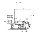
図11はDIN式コネクター組立体17dを示す図であり、この場合にはコネクター組立体17dにはパイロット組立体16の表面方向に向けて通電ケーブル75を案内するためのガイド筒96が設けられている。
【0062】
図12はプラグイン式のコネクター組立体17eを示す図であり、このコネクター組立体17eはスタッキングタイプのマニホールド電磁弁とする場合に使用され、ケーブル収容孔97を有している。電磁弁10を積層すると、ケーブル収容孔97によって共通のケーブル配線用の通路が形成されることになる。
【0063】
図11および図12に示すタイプのコネクター組立体17d,17eにあっても、第1係合部に係合する第2係合部92が設けられている。
【0064】
このように、グロメット式、DIN式およびプラグイン式のいずれのタイプのコネクターをも装着することができる。
【0065】
本発明は前記実施の形態に限定されるものではなく、その要旨を逸脱しない範囲で種々変更可能であることはいうまでもない。
【0066】
たとえば、図1は本発明の電磁弁10を複数個マニホールドブロック11に搭載するようにしたブロックタイプのマニホールド電磁弁を示すが、複数の電磁弁を積層するようにしたスタッキングタイプの電磁弁とするようにしても良く、電磁弁10を単体として使用するようにしても良い。
【0067】
【発明の効果】
以上のように、本発明にあっては、パイロット組立体の内部に収容空間を形成し、その中に着脱自在にパイロット電磁弁を装着し得るようにし、パイロット組立体に開閉自在にカバーを設けたので、パイロット電磁弁の取付け、取外しおよび交換作業をカバーを開くことによって容易に行うことができる。パイロット電磁弁に設けられた手動操作ボタンを操作する際には、カバーに開閉自在に設けられた蓋部材を開くことにより容易にその操作を行うことができるとともに、蓋部材を閉じておくことによって不用意に手動操作ボタンが操作されることを防止することができる。カバーがパイロット組立体の中に収容されたパイロット電磁弁を締結するようにすることにより、パイロット電磁弁の取付け作業を容易に行うことができる。パイロット組立体に装着されるコネクター組立体を複数種類用意しておき、それぞれのコネクター組立体にパイロット組立体に設けられた第1係合部に係合する共通の第2係合部を形成しておくことにより、複数の種類のコネクター組立体をパイロット組立体に取り付けることができる。
【図面の簡単な説明】
【図1】本発明の一実施の形態である電磁弁を積層したマニホールド電磁弁を示す斜視図である。
【図2】図1の正面図である。
【図3】(A)は図2の平面図であり、(B)はカバー開いた状態における同図(A)の一部を示す平面図である。
【図4】電磁弁の内部構造を示す断面図である。
【図5】パイロット電磁弁を示す拡大平面図である。
【図6】図5の断面図である。
【図7】(A)はパイロット組立体に設けられ、蓋部材が閉じた状態におけるカバーを示す斜視図であり、(B)は蓋部材が開いた状態におけるカバーを示す斜視図である。
【図8】(A)は図4に示されたコネクター組立体の底面図であり、(B)はパイロット組立体の底面図であり、(C)は図4の左側面図である。
【図9】他のタイプのコネクター組立体を示す断面図である。
【図10】さらに他のタイプのコネクター組立体を示す断面図である。
【図11】さらに他のタイプのコネクター組立体を示す断面図である。
【図12】さらに他のタイプのコネクター組立体を示す断面図である。
【符号の説明】
10 電磁弁
11 マニホールドブロック
12 主弁ブロック
15 主弁組立体
16 パイロット組立体
17a〜17e コネクター組立体
22 主弁軸
23 第1ピストン
24 第2ピストン
31 給気ポート
32,33 排気ポート
34 第1空気圧室
35 第2空気圧室
36 パイロット流路
37 第1パイロット電磁弁
38 第2パイロット電磁弁
41 カバー
42 ケース部
43 収容空間
73 ソケット部
74 通電プラグ
75 通電ケーブル
76 手動操作ボタン
85 蓋部材
91 第1係合部
92 第2係合部
95 名板収容溝[0001]
BACKGROUND OF THE INVENTION
The present invention relates to an indirectly operated solenoid valve that switches a flow path by moving a main valve shaft in the axial direction by operation of a pilot solenoid valve.
[0002]
[Prior art]
The indirectly operated solenoid valve for switching the flow path has a main valve assembly with a main valve shaft and a pilot assembly with a pilot solenoid valve installed, and is used as a single solenoid valve. In addition, it may be used as a manifold solenoid valve in which a plurality of solenoid valves are combined into a manifold.
[0003]
As a manifold solenoid valve, a plurality of solenoid valves are mounted on a manifold block in which a common air supply flow path and exhaust flow path are formed, and the air supply holes and exhaust holes of each solenoid valve are respectively connected to the air supply air flow of the manifold block. A plurality of solenoid valves, each having a block type that communicates with a passage and an exhaust passage, an air communication hole that communicates with the air supply hole, and an exhaust communication hole that communicates with the exhaust hole in the main valve block of the solenoid valve. There is a stacking type in which a common air supply passage and exhaust passage are formed by the air supply communication hole and the exhaust communication hole of each main valve block.
[0004]
For indirectly operated solenoid valves, whether the solenoid valve is used as a single solenoid valve or multiple manifold solenoid valves, the switching position of the main valve shaft of the solenoid valve For example, Japanese Patent Application Laid-Open No. 7-198054 has been developed which allows the user to arbitrarily switch to any of the return types.
[0005]
The self-holding type operates two pilot solenoid valves, and is also called a double solenoid type. Pilot fluid is supplied to and discharged from the pneumatic chambers provided at both ends of the main valve shaft. When the pilot solenoid valve is operated, the main valve shaft is switched to one position, and even if the operation is stopped, that position is maintained.When the other pilot solenoid valve is operated, the main valve shaft is switched to the other position, Even if the operation is stopped, the position is maintained.
[0006]
On the other hand, the self-recovery type is in a state in which the pilot fluid is always supplied to one pneumatic chamber, and the main valve shaft is driven by the operation of one pilot solenoid valve, which is also called a single solenoid type. When the pilot solenoid valve is operated and pilot fluid is supplied to the other pneumatic chamber, the main valve shaft switches. When the operation is stopped, the main valve shaft returns to its original position by the pilot fluid supplied to one pneumatic chamber. Will do.
[0007]
[Problems to be solved by the invention]
In the conventional solenoid valve that can be switched to both types, two pilot solenoid valves are molded in the pilot assembly, and only one pilot solenoid valve is used. When done, the other pilot solenoid valve cannot be removed.
[0008]
In order to supply electric power to the pilot solenoid valve, a connector is connected to the pilot solenoid valve. For example, a grommet type, a cabtire cable type, a DIN connector type, There are various types such as a plug-in type.
[0009]
Conventionally, a plurality of types of pilot assemblies are prepared in accordance with each connector type, and there is a problem that the number of parts increases.
[0010]
An object of the present invention is to enable easy replacement of a pilot solenoid valve.
[0011]
Another object of the present invention is to enable attachment of a plurality of connectors of different types.
[0012]
[Means for Solving the Problems]
The solenoid valve of the present invention is formed with a valve hole that slidably accommodates a main valve shaft whose both ends are disposed in a cylinder chamber in the axial direction, and fluid from an air supply hole formed by opening the valve hole. A main valve assembly in which a plurality of output ports from which gas flows out is formed, a pilot assembly attached to the main valve assembly and provided with a storage space, and at least one of the cylinders mounted in the storage space At least one pilot solenoid valve for supplying a pilot fluid to the chamber, and is provided on the surface of the pilot assembly so as to be openable and closable. Opened when attaching and detaching the pilot solenoid valve A cover, A lid member that is openably and closably attached to the cover in correspondence with a manual operation button provided on the pilot solenoid valve; Have The manual operation button was covered with a lid member It is characterized by that.
[0013]
The solenoid valve according to the present invention is characterized in that the pilot solenoid valve is fixed in the housing space by the cover. Further, the solenoid valve of the present invention is provided in the pilot assembly. A first engaging portion is provided, and a second engaging portion that engages with the first engaging portion is provided in the connector assembly, and the type is different. Connector assembly The The pilot assembly can be mounted. Furthermore, the solenoid valve of the present invention is characterized in that the connector assembly is provided with a name plate mounting portion to which a name plate displaying a model number or the like is detachably mounted.
[0014]
DETAILED DESCRIPTION OF THE INVENTION
Hereinafter, embodiments of the present invention will be described in detail with reference to the drawings.
[0015]
1 is a perspective view showing an electromagnetic valve according to an embodiment of the present invention, FIG. 2 is a front view of FIG. 1, and FIG. 3 (A) is a plan view of FIG.
[0016]
The solenoid valve of the present invention can be used alone, or can be used as a block type manifold solenoid valve in which a plurality of solenoid valves are mounted on a manifold block, and further formed by stacking a plurality of solenoid valves. It can also be used as a stacking type manifold solenoid valve in which end blocks are arranged on both sides of the laminated solenoid valve.
[0017]
FIG. 1 shows a block type manifold solenoid valve in which a plurality of
[0018]
As shown in FIG. 2, each
[0019]
Each
[0020]
The
[0021]
The
[0022]
The
[0023]
A
[0024]
A
[0025]
As shown in FIGS. 2 and 3, the
[0026]
Each of the
[0027]
As shown in FIG. 4, the
[0028]
FIG. 5 is an enlarged plan view showing the first
[0029]
As shown in FIG. 6, the first
[0030]
The second
[0031]
A first pilot pressure input path 44 corresponding to the first pilot
[0032]
The first pilot pressure output path 45 of the first
[0033]
As shown in FIG. 4, in the first pilot pressure output path 45, the air flow from the output port 45a toward the first
[0034]
Similarly to the first pilot pressure output path 45, the second pilot
[0035]
Thus, the pilot fluid is supplied to the two
[0036]
In this case, the pilot fluid is supplied from the
[0037]
On the other hand, when the second
[0038]
However, when the pilot fluid is always supplied to the second
[0039]
In this case, the pilot fluid is always supplied to the second
[0040]
On the other hand, when the energization of the
[0041]
Two
[0042]
Output passages 26b and 27b corresponding to the respective output ports A and B are formed in the bottom surface of the
[0043]
As shown in FIG. 6, a
[0044]
As shown in FIGS. 5 and 6, the
[0045]
As shown in FIG. 4, the
[0046]
In order to manually operate the
[0047]
The
[0048]
As described above, when the
[0049]
As shown in FIG. 5, the
[0050]
FIG. 7 is a diagram showing the
[0051]
The
[0052]
As shown in FIG. 7, the
[0053]
Thus, the
[0054]
8A is a bottom view of the
[0055]
The
[0056]
As shown in FIGS. 8A and 8C, a name
[0057]
In addition to the
[0058]
FIG. 9 is a diagram showing an ellipsoidal grommet
[0059]
FIG. 10 is a view showing a cabtire cable
[0060]
The
[0061]
FIG. 11 is a view showing a
[0062]
FIG. 12 is a view showing a plug-in
[0063]
Even in the
[0064]
Thus, any type of grommet type, DIN type and plug-in type connectors can be mounted.
[0065]
It goes without saying that the present invention is not limited to the above-described embodiment, and various modifications can be made without departing from the scope of the invention.
[0066]
For example, FIG. 1 shows a block-type manifold solenoid valve in which a plurality of
[0067]
【The invention's effect】
As described above, in the present invention, an accommodation space is formed inside the pilot assembly, and a pilot solenoid valve can be removably mounted therein, and a cover is provided on the pilot assembly so as to be opened and closed. Therefore, the pilot solenoid valve can be easily attached, removed and replaced by opening the cover. When operating the manual operation button provided on the pilot solenoid valve, the operation can be easily performed by opening the cover member that can be opened and closed on the cover, and by closing the cover member. It is possible to prevent the manual operation button from being inadvertently operated. By attaching the pilot electromagnetic valve accommodated in the pilot assembly to the cover, the pilot electromagnetic valve can be easily attached. A plurality of types of connector assemblies to be attached to the pilot assembly are prepared, and a common second engagement portion that engages with the first engagement portion provided in the pilot assembly is formed in each connector assembly. Thus, a plurality of types of connector assemblies can be attached to the pilot assembly.
[Brief description of the drawings]
FIG. 1 is a perspective view showing a manifold electromagnetic valve in which electromagnetic valves according to an embodiment of the present invention are stacked.
FIG. 2 is a front view of FIG. 1;
3A is a plan view of FIG. 2, and FIG. 3B is a plan view showing a part of FIG.
FIG. 4 is a cross-sectional view showing the internal structure of the electromagnetic valve.
FIG. 5 is an enlarged plan view showing a pilot solenoid valve.
6 is a cross-sectional view of FIG.
7A is a perspective view showing the cover provided in the pilot assembly and in a state where the lid member is closed, and FIG. 7B is a perspective view showing the cover in a state where the lid member is opened.
8A is a bottom view of the connector assembly shown in FIG. 4, FIG. 8B is a bottom view of the pilot assembly, and FIG. 8C is a left side view of FIG.
FIG. 9 is a cross-sectional view showing another type of connector assembly.
FIG. 10 is a cross-sectional view showing still another type of connector assembly.
FIG. 11 is a cross-sectional view showing still another type of connector assembly.
FIG. 12 is a cross-sectional view showing still another type of connector assembly.
[Explanation of symbols]
10 Solenoid valve
11 Manifold block
12 Main valve block
15 Main valve assembly
16 Pilot assembly
17a-17e Connector assembly
22 Main valve stem
23 First piston
24 Second piston
31 Air supply port
32, 33 Exhaust port
34 First pneumatic chamber
35 Second pneumatic chamber
36 Pilot flow path
37 1st pilot solenoid valve
38 Second pilot solenoid valve
41 Cover
42 Case part
43 accommodation space
73 Socket part
74 Power plug
75 Power cable
76 Manual operation buttons
85 Lid member
91 1st engaging part
92 2nd engaging part
95 Name plate receiving groove
Claims (4)
前記主弁組立体に取り付けられ、収容空間が設けられたパイロット組立体と、前記収容空間内に装着され、少なくとも一方の前記シリンダ室にパイロット流体を供給する少なくとも1つのパイロット電磁弁と、
前記パイロット組立体の表面に開閉自在に設けられ、前記パイロット電磁弁を着脱する際に開かれるカバーと、
前記パイロット電磁弁に設けられた手動操作ボタンに対応させて前記カバーに開閉自在に装着される蓋部材とを有し、
前記手動操作ボタンが蓋部材により覆われるようにしたことを特徴とする電磁弁。A plurality of output ports through which a fluid is discharged from an air supply hole formed by opening a valve hole that slidably accommodates a main valve shaft having both ends disposed in the cylinder chamber in the axial direction. A main valve assembly formed with
A pilot assembly attached to the main valve assembly and provided with a storage space; and at least one pilot solenoid valve mounted in the storage space and supplying pilot fluid to at least one of the cylinder chambers;
A cover that can be freely opened and closed on the surface of the pilot assembly, and is opened when the pilot solenoid valve is attached and detached;
A lid member that is openably and closably attached to the cover in correspondence with a manual operation button provided on the pilot solenoid valve;
An electromagnetic valve characterized in that the manual operation button is covered with a lid member.
Priority Applications (1)
| Application Number | Priority Date | Filing Date | Title |
|---|---|---|---|
| JP27093099A JP4233707B2 (en) | 1999-09-24 | 1999-09-24 | solenoid valve |
Applications Claiming Priority (1)
| Application Number | Priority Date | Filing Date | Title |
|---|---|---|---|
| JP27093099A JP4233707B2 (en) | 1999-09-24 | 1999-09-24 | solenoid valve |
Publications (2)
| Publication Number | Publication Date |
|---|---|
| JP2001090861A JP2001090861A (en) | 2001-04-03 |
| JP4233707B2 true JP4233707B2 (en) | 2009-03-04 |
Family
ID=17492988
Family Applications (1)
| Application Number | Title | Priority Date | Filing Date |
|---|---|---|---|
| JP27093099A Expired - Fee Related JP4233707B2 (en) | 1999-09-24 | 1999-09-24 | solenoid valve |
Country Status (1)
| Country | Link |
|---|---|
| JP (1) | JP4233707B2 (en) |
Families Citing this family (1)
| Publication number | Priority date | Publication date | Assignee | Title |
|---|---|---|---|---|
| JP4129687B2 (en) * | 2004-04-22 | 2008-08-06 | Smc株式会社 | Solenoid valve with manual button |
-
1999
- 1999-09-24 JP JP27093099A patent/JP4233707B2/en not_active Expired - Fee Related
Also Published As
| Publication number | Publication date |
|---|---|
| JP2001090861A (en) | 2001-04-03 |
Similar Documents
| Publication | Publication Date | Title |
|---|---|---|
| US6095489A (en) | Double- or single-solenoid type selector valve encapsulated in resin | |
| US5558126A (en) | Double solenoid type electromagnetic valve | |
| KR100415784B1 (en) | Manifold valve having position detecting function | |
| US5615710A (en) | Pilot-type change-over valve | |
| EP0655575B1 (en) | Electromagnetic pilot type selector valve | |
| KR0130580Y1 (en) | Power supply of solenoid valve assembly | |
| EP0661484A1 (en) | Double-solenoid type electromagnetic valve | |
| JP4228370B2 (en) | Solenoid pilot type switching valve | |
| EP0915259B1 (en) | Directional control valve connector device | |
| US5996629A (en) | Pilot solenoid valve | |
| US7677264B2 (en) | Manifold-type solenoid valve with external port | |
| JP3853700B2 (en) | solenoid valve | |
| JP4167779B2 (en) | solenoid valve | |
| JP4233707B2 (en) | solenoid valve | |
| KR100302412B1 (en) | Pilot Switching Valve | |
| JP3959562B2 (en) | Pilot type switching valve | |
| JP2008209009A (en) | Solenoid valve | |
| JPH09273651A (en) | Pilot-type solenoid valve | |
| US6766828B2 (en) | Interlock valve | |
| KR0120951Y1 (en) | Double solenoid type electromagnetic valve | |
| KR100435864B1 (en) | Magnetic valve | |
| JPH05231558A (en) | Valve unit | |
| JP2771448B2 (en) | solenoid valve | |
| JP2003100513A (en) | Electric signal feeding unit of solenoid valve |
Legal Events
| Date | Code | Title | Description |
|---|---|---|---|
| A621 | Written request for application examination |
Free format text: JAPANESE INTERMEDIATE CODE: A621 Effective date: 20051018 |
|
| A977 | Report on retrieval |
Free format text: JAPANESE INTERMEDIATE CODE: A971007 Effective date: 20080403 |
|
| A131 | Notification of reasons for refusal |
Free format text: JAPANESE INTERMEDIATE CODE: A131 Effective date: 20080415 |
|
| A521 | Written amendment |
Free format text: JAPANESE INTERMEDIATE CODE: A523 Effective date: 20080529 |
|
| A131 | Notification of reasons for refusal |
Free format text: JAPANESE INTERMEDIATE CODE: A131 Effective date: 20080902 |
|
| A521 | Written amendment |
Free format text: JAPANESE INTERMEDIATE CODE: A523 Effective date: 20081010 |
|
| TRDD | Decision of grant or rejection written | ||
| A01 | Written decision to grant a patent or to grant a registration (utility model) |
Free format text: JAPANESE INTERMEDIATE CODE: A01 Effective date: 20081202 |
|
| A01 | Written decision to grant a patent or to grant a registration (utility model) |
Free format text: JAPANESE INTERMEDIATE CODE: A01 |
|
| A61 | First payment of annual fees (during grant procedure) |
Free format text: JAPANESE INTERMEDIATE CODE: A61 Effective date: 20081210 |
|
| FPAY | Renewal fee payment (event date is renewal date of database) |
Free format text: PAYMENT UNTIL: 20111219 Year of fee payment: 3 |
|
| R150 | Certificate of patent or registration of utility model |
Free format text: JAPANESE INTERMEDIATE CODE: R150 |
|
| S531 | Written request for registration of change of domicile |
Free format text: JAPANESE INTERMEDIATE CODE: R313531 |
|
| FPAY | Renewal fee payment (event date is renewal date of database) |
Free format text: PAYMENT UNTIL: 20111219 Year of fee payment: 3 |
|
| R350 | Written notification of registration of transfer |
Free format text: JAPANESE INTERMEDIATE CODE: R350 |
|
| FPAY | Renewal fee payment (event date is renewal date of database) |
Free format text: PAYMENT UNTIL: 20121219 Year of fee payment: 4 |
|
| FPAY | Renewal fee payment (event date is renewal date of database) |
Free format text: PAYMENT UNTIL: 20121219 Year of fee payment: 4 |
|
| FPAY | Renewal fee payment (event date is renewal date of database) |
Free format text: PAYMENT UNTIL: 20131219 Year of fee payment: 5 |
|
| R250 | Receipt of annual fees |
Free format text: JAPANESE INTERMEDIATE CODE: R250 |
|
| R250 | Receipt of annual fees |
Free format text: JAPANESE INTERMEDIATE CODE: R250 |
|
| R250 | Receipt of annual fees |
Free format text: JAPANESE INTERMEDIATE CODE: R250 |
|
| LAPS | Cancellation because of no payment of annual fees |