JP4202805B2 - Wire rope breakage detection device - Google Patents
Wire rope breakage detection device Download PDFInfo
- Publication number
- JP4202805B2 JP4202805B2 JP2003101053A JP2003101053A JP4202805B2 JP 4202805 B2 JP4202805 B2 JP 4202805B2 JP 2003101053 A JP2003101053 A JP 2003101053A JP 2003101053 A JP2003101053 A JP 2003101053A JP 4202805 B2 JP4202805 B2 JP 4202805B2
- Authority
- JP
- Japan
- Prior art keywords
- wire rope
- wire
- elevator
- pair
- frame members
- Prior art date
- Legal status (The legal status is an assumption and is not a legal conclusion. Google has not performed a legal analysis and makes no representation as to the accuracy of the status listed.)
- Expired - Fee Related
Links
- 238000001514 detection method Methods 0.000 title claims description 46
- 239000004927 clay Substances 0.000 claims description 14
- 238000003780 insertion Methods 0.000 claims description 13
- 230000037431 insertion Effects 0.000 claims description 13
- 229910000831 Steel Inorganic materials 0.000 claims description 11
- 239000010959 steel Substances 0.000 claims description 11
- 238000004804 winding Methods 0.000 claims description 10
- 239000000463 material Substances 0.000 claims description 9
- 239000011248 coating agent Substances 0.000 claims description 4
- 238000000576 coating method Methods 0.000 claims description 4
- 125000006850 spacer group Chemical group 0.000 description 6
- 229910052602 gypsum Inorganic materials 0.000 description 5
- 239000010440 gypsum Substances 0.000 description 5
- 238000007689 inspection Methods 0.000 description 5
- 229920003002 synthetic resin Polymers 0.000 description 4
- 239000000057 synthetic resin Substances 0.000 description 4
- 239000003973 paint Substances 0.000 description 3
- 230000002093 peripheral effect Effects 0.000 description 3
- 239000005909 Kieselgur Substances 0.000 description 2
- VYPSYNLAJGMNEJ-UHFFFAOYSA-N Silicium dioxide Chemical compound O=[Si]=O VYPSYNLAJGMNEJ-UHFFFAOYSA-N 0.000 description 2
- PPBRXRYQALVLMV-UHFFFAOYSA-N Styrene Chemical compound C=CC1=CC=CC=C1 PPBRXRYQALVLMV-UHFFFAOYSA-N 0.000 description 2
- 239000000853 adhesive Substances 0.000 description 2
- 230000001070 adhesive effect Effects 0.000 description 2
- 239000003638 chemical reducing agent Substances 0.000 description 2
- 230000008878 coupling Effects 0.000 description 2
- 238000010168 coupling process Methods 0.000 description 2
- 238000005859 coupling reaction Methods 0.000 description 2
- 230000004907 flux Effects 0.000 description 2
- 238000012423 maintenance Methods 0.000 description 2
- 238000004519 manufacturing process Methods 0.000 description 2
- 239000002184 metal Substances 0.000 description 2
- 239000011347 resin Substances 0.000 description 2
- 229920005989 resin Polymers 0.000 description 2
- 239000004925 Acrylic resin Substances 0.000 description 1
- 229920000178 Acrylic resin Polymers 0.000 description 1
- BZHJMEDXRYGGRV-UHFFFAOYSA-N Vinyl chloride Chemical compound ClC=C BZHJMEDXRYGGRV-UHFFFAOYSA-N 0.000 description 1
- 230000001174 ascending effect Effects 0.000 description 1
- 238000005452 bending Methods 0.000 description 1
- 230000000694 effects Effects 0.000 description 1
- 230000003028 elevating effect Effects 0.000 description 1
- 239000000123 paper Substances 0.000 description 1
- 239000012188 paraffin wax Substances 0.000 description 1
- 238000007665 sagging Methods 0.000 description 1
- 238000000926 separation method Methods 0.000 description 1
- 230000032258 transport Effects 0.000 description 1
- 230000000007 visual effect Effects 0.000 description 1
Images


Landscapes
- Maintenance And Inspection Apparatuses For Elevators (AREA)
- Lift-Guide Devices, And Elevator Ropes And Cables (AREA)
Description
【0001】
【発明の属する技術分野】
本発明はワイヤロープの素線切れ検知装置に関する。さらに詳しくは、エレベータ等に使用されるワイヤロープを構成するたとえば鋼線からなる素線の一部が切断した場合にこれを検知するための素線切れ検知装置に関する。
【0002】
【従来の技術】
従来、ビルの人用エレベータや駐車装置の車両昇降用エレベータは定期的に保守点検を行うことが義務づけられており、ワイヤロープの素線切れの有無も点検項目に含まれている。通常は数百メートルに及ぶその全長にわたって点検を行う必要があり、非常に時間のかかる重労働である。
【0003】
そこで、ワイヤロープの素線切れを検査する装置が種々提案されている。たとえば、一対の磁極(S−N)間に被検ワイヤロープを挿通し、このロープ部分を磁束が通るように構成したものが知られている(特許文献1および特許文献2)。いずれも磁束の変化を検出する検出器が装備されている。また、いずれの装置も、これを被検ワイヤロープに沿って移動させながら素線切れを検査するものである。
【0004】
また、僅かに離間した一対の電極を被検ワイヤロープに近接して設置するものが提案されている(特許文献3)。被検ワイヤロープの素線が切断しているとほとんどの場合その切断先端部分がワイヤロープから外方へ飛び出している。そこで、この飛び出し部分が一対の電極に接触すると両者を導通させるので、これを検出することにより切断を検知しようというものである。
【0005】
圧力センサを用いた切断検出装置も提案されている。この装置はその内部をワイヤロープが通過する二分割された漏斗状筒体と、その外部に、圧力センサを介して備えられた保持具とからなる(特許文献4)。素線の切断部が飛び出しているとこれが漏斗状筒体をひっかけて引きずり、上記圧力センサを作動させるので検知することができるというものである。
【0006】
内部に弾性舌片を備えた筒状体からなる検出具が提案されている(特許文献5)。この筒状体に被検ワイヤロープを挿通し、その状態で筒状体をワイヤロープに沿って移動させていくと、素線切れがあればその部分が弾性舌片に引っかかり、移動が停止する。これによって素線切れを検出しようというものである。
【0007】
ワイヤロープの通過位置に、細い導線につながれた可動体を設置した装置が提案されている(特許文献6)。ワイヤロープの移動に伴い、飛び出した素線切れ部分がこの可動体を引っかけて移動させたとき、上記導線が切断するのでこれによって素線切れを検知しようというものである。
【0008】
【特許文献1】
特開平11−230947号公報
【特許文献2】
特開2000−241393号公報
【特許文献3】
特開2001−151433号公報
【特許文献4】
特開平8−119539号公報
【特許文献5】
実公平5−20779号公報
【特許文献6】
実開平6−73071号公報
【0009】
【発明が解決しようとする課題】
しかしながら、特許文献1〜4、6の装置は電気的、磁気的に検出する装置であり、大がかりで高価なものとなる。特許文献1、2、5は長い被検ワイヤロープに沿って装置を移動させていかなければならず、重労働となる。また、特許文献3の装置の場合、実際に両電極をうまく導通するように切断部が接触するか疑問である。さらに、素線の切断部が実際に可動体を動かし得るのかが疑問である。
【0010】
本発明はかかる課題を解決するためになされたものであり、構成が簡単で且つ安価であり、簡単な作業で素線切れを検知することができるワイヤロープの素線切れ検知装置、および、この検知装置を備えたエレベータ昇降装置を提供することを目的としている。
【0011】
【課題を解決するための手段】
本発明のワイヤロープの素線切れ検知装置は、ワイヤロープに近接して設置され得る、鋼線の当接によって損傷する易損傷部材を有している。ワイヤロープは素線が切断するとその先端部分がワイヤロープから外方へ飛び出しているので、ワイヤロープの移動に伴って上記素線の切断先端部が易損傷部材を傷つけるかまたは破損することによって接触した痕跡を残す。この痕跡を見つければ素線切れがあることが確認できる。このように、複雑高価な電気的、磁気的装置を用いることなく、また、長いワイヤロープに沿って装置を移動させる必要もなく、素線切れの有無を容易に確認することができる。
【0012】
上記易損傷部材がワイヤロープの周囲を非接触で取り囲むように、この易損傷部材にワイヤロープが挿通する挿通孔を形成しておくのが好ましい。素線切れの検知精度が向上するからである。
【0013】
本発明の他のワイヤロープ素線切れ検知装置は、
相互に開閉可能な一対の枠部材と、各枠部材の内部に設置された、鋼線の当接によって損傷する易損傷部材とを備えており、この易損傷部材の端辺に、一対の枠部材同士が閉じたときにワイヤロープが挿通し得る挿通孔を構成する半円状切り欠きが形成されている。
【0014】
かかる構成により、製造および設置が容易となり、しかも素線切れの検知精度が向上した素線切れ検知装置が実現する。
【0015】
本発明のさらに他のワイヤロープ素線切れ検知装置は、
凹部を有する、相互に開閉可能な一対の枠部材と、各枠部材の凹部内に設置された、鋼線の当接によって損傷する易損傷部材とを備えており、この易損傷部材が直線状の辺部を有しており、一対の枠部材が閉じたときに易損傷部材の辺部同士が平行となってワイヤロープの直径より僅かに大きい隙間を形成する。
【0016】
かかる構成によっても、製造および設置が容易な素線切れ検知装置が実現する。
【0017】
上記易損傷部材を、紙、粘土、および、ワイヤロープに対向する面に塗料が塗工された部材のうちのいずれか一、またはその組み合わせから構成するのが好ましい。素線の切断端部によって傷や破損が生じやすく、切断端部の通過の痕跡が明瞭に目視できるからである。
【0018】
本発明のエレベータ昇降装置は、
一端にエレベータが取り付けられ、他端にカウンターウエイトが取り付けられたエレベータ昇降用のワイヤロープと、駆動モータと、この駆動モータによって回転駆動される、上記ワイヤロープを巻き上げるための駆動シーブと、この駆動シーブに近接して配置される転向シーブと、上記駆動シーブと転向シーブとの間のワイヤロープの通過路に設置されたワイヤロープの素線切れ検知装置とを備えており、この素線切れ検知装置が、前述したもののうちいずれか一の素線切れ検知装置から構成されている。
【0019】
本発明の他のエレベータ昇降装置は、
一端にエレベータが取り付けられたエレベータ昇降用のワイヤロープと、駆動モータと、この駆動モータによって回転駆動される、上記ワイヤロープを巻き取り且つ繰り出すための巻き上げドラムと、この巻き上げドラムの近傍におけるワイヤロープの通過路に設置されたワイヤロープの素線切れ検知装置とを備えており、この素線切れ検知装置が、前述したもののうちいずれか一の素線切れ検知装置から構成されている。
【0020】
【発明の実施の形態】
添付の図面を参照しながら本発明の素線切れ検知装置(以下、単に検知装置という)の実施形態、および、この検知装置を備えたエレベータ昇降装置の実施形態を説明する。
【0021】
図1は本発明のエレベータ昇降装置が適用され得るエレベータ式駐車装置(以下、単に駐車装置という)の一例を示す正面断面図である。
【0022】
この駐車装置1の内部には、車両搭載用のパレット2を昇降させるためのエレベータ3がワイヤロープ4によって吊り下げられており、このワイヤロープ4を巻き上げ繰り出してエレベータ3を昇降させる駆動装置(巻き上げ装置)5およびカウンターウエイト6が備えられている。エレベータ3の昇降路7の両側には車両Mを収容するための多数段の駐車棚(以下、単に棚ともいう)8が配設されている。各棚8の上にはパレット2が横行し得るレール(図示しない)が配設されており、このレール上にパレット2が載置される。
【0023】
エレベータ3は両側の棚8の間を昇降し、呼び出されたパレット2の棚8まで移動したうえで当該パレット2を受け取り、これを入出庫階Eへ搬送する。また、入出庫階Eから指定された棚8まで車両Mを載せたパレット2を搬送して預け入れる。本駐車装置1では入出庫階Eは一番下の床面(1階)とされている。エレベータ3にはパレットが横行するためのレール(図示しない)が敷設されている。エレベータ3が車両Mの受け渡しのために棚8の位置に至ると上記レール同士が対向する。また、エレベータ3には、棚8からパレット2を受け取り且つ戻すための図示しない移動装置が配設されている。
【0024】
図2および図3には上記エレベータ3およびその駆動装置5が示されている。エレベータ3はワイヤロープ4によってカウンターウエイト6と重量釣り合い状態で連結されている。符号10はエレベータ3の昇降ガイドレールである。ワイヤロープ4は、その中間部が駆動装置5の巻き上げシーブ(駆動シーブという)11および転向シーブ12に巻き掛けられている。ワイヤロープ4は駆動シーブ11から出て複数個の転向プーリ12を経てほぼ矩形のエレベータ3の四隅に接続されている。また、駆動シーブ11から出て転向シーブ12に巻き掛けられた上でカウンターウエイト6に接続されている。駆動シーブ11には減速機13を介して駆動モータ14が連結されている。符号15はカップリングである。
【0025】
そして、モータ14によって駆動シーブ11を回転させ、駆動シーブ11の摩擦力によってワイヤロープ4を引いてエレベータ3を昇降させている。カウンターウエイト6の重量によって駆動装置5の上昇力と下降力との均一化を図っている。本実施形態ではエレベータ3の四隅それぞれに三本のワイヤロープ4が連結されているので各シーブ11、12には十二本のロープ4が巻き掛けられるように、ロープ一本ごとの溝16が形成されている。そして、当然ながら両シーブ11、12間の十二本のロープ部分はそれぞれ張力によってたるむことなく直線状になっている。この部分では、各ロープ4がシーブ11、12の溝16に係合し、張力によって張られているので、その長手方向に垂直の方向(ロープの断面半径方向)には変位することがなく整列している。この直線状となったロープ部分に素線切れ検知装置(以下、単に検知装置という)20が設置されている。
【0026】
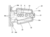
図4に示すように、この検知装置20はヒンジ21によって相互に開閉可能な一対のコ字状の枠部材22を有し、各枠部材22の内側(凹状になっている部分)に鋼線の当接によって損傷する易損傷部材23が取り付けられている。枠部材22は金属製や合成樹脂製の棒材を半円状、C字状、コ字状に屈曲して形成することができる。上記「鋼線」とはワイヤロープ4の素線であるスチールワイヤを意味している。易損傷部材23としては、油紙、パラフィン紙、ケント紙、段ボール紙等を含む紙全般、紙粘土板や珪藻土板等を含む粘土板、および、石膏板、並びに、これらの組み合わせが好ましい。
【0027】
易損傷部材23が紙の場合には、この紙の面がピンと張るように接着剤によって枠部材22に貼着する。上記一対の枠部材22を相互に閉じたときに対向する易損傷部材23の辺23aは直線状に形成されている。また、枠部材22のヒンジ21側(基端部)と反対側の端部(先端部)にはスペーサ24aと取付部24bとが形成されている。枠部材22が閉じたときにはこのスペーサ24aにより、上記辺23a同士の間に被検ワイヤロープの直径より僅かに大きい間隙Dが形成され、両辺23aが平行となるようにされている。図示のごとく、この検知装置20は整列した複数本のワイヤロープ4が上記間隙D内に並ぶように所定位置に取り付けられる。このとき、ワイヤロープ4の外周面と易損傷部材23の辺23aとの最短離間距離を小さくしておいてもよい。ワイヤロープ4がその半径方向にほとんど変位しないからである。そして、先端部の取付部24bをブラケット27等にボルト止めする。
【0028】
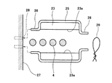
図5に示すように、上記ヒンジやスペーサを設けずに一対のコ字状枠部材25を別体に形成してもよい。そして、図示のごとく各枠部材25の両端部を外方へ突出させて突出部26を形成しておく。一方、所定位置にブラケット27を配設してこれに一方の突出部26が挿入係止される二個の挿入孔28を所定間隔をあけて穿設しておく。こうすることにより、枠部材25を一個ずつ取り付けることができる。その後、二個の枠部材25の他方の突出部26同士を針金等によって固縛すればよい(図6参照)。
【0029】
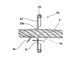
図6および図7に示すように、このワイヤロープ4に素線切れがあると切れた素線4aがロープ外に突出しているため、ワイヤロープ4の通過に伴って素線4aが易損傷部材23(紙)を破損Bさせる。つまり、紙の辺23aの部分を素線が切る。エレベータ3の点検時にこの検知装置20に接近して紙の辺23aを目視することにより、ワイヤロープ4の素線切れの有無を容易に確認することができる。
【0030】
図8には他の検知装置30が示されている。この検知装置30に使用する易損傷部材31は紙ではなく、珪藻土、粘土、紙粘土などからなる粘土板、または石膏板である。粘土板(石膏板)は紙より厚いので一対の枠部材32はそれぞれ幅の広い棒材または板材から形成される。枠部材32の全体形状は上記と同様にコ字状を呈している。粘土板は枠部材32の内側に接着剤などによって取り付けられるが、これに限定されない。たとえば、枠部材32の内側に粘土板の周縁が嵌着される溝を形成しておいてもよい。
【0031】
上記易損傷部材31の対向辺31aは直線状ではなく、枠部材32が閉じたときにワイヤロープ4が通過しうる挿通孔33を構成する半円状の切り欠き34が複数個形成されている。挿通孔33の内径はワイヤロープの断面直径より若干大きく、ワイヤロープが通過しても挿通孔33の内面に接触しない。切り欠き34の内周面は凹凸のない滑らかな面にされている。したがって、切断したワイヤが摺接することにより目視で明瞭に確認できる痕跡(掻き傷など)が付く。もちろん、薄い粘土板(石膏板)を用い、切断したワイヤが摺接することによって破損するようにしてもよい。
【0032】
一対の枠部材32はそれらの基端部にヒンジ21を有し、これらによって相互に開閉可能にされている。枠部材32の先端部にはスペーサ35と取付部36とが形成されている。枠部材32が閉じたときにはこのスペーサ35の当接により、粘土板の不用意な損傷が防止される。また、先端部の取付部36をブラケット27等にボルト止めして検知装置30が設置される。
【0033】
このように挿通孔33を構成し得る易損傷部材31の材料は粘土板に限定されない。段ボール紙など、挿通孔33の形状を維持することができるものであればよい。要するに、切断したワイヤが摺接することによって容易に傷が付く材料であればよい。以下に他の例を説明する。
【0034】
図9には、二分割された複数個の管部材38aが平行に整列して接合された一対の枠部材38からなる検知装置37が示されている。この一対の枠部材38は基端部のヒンジ21によって相互に開閉可能にされている。一対の枠部材38が閉じて重ね合わされたときに、ワイヤロープ4が通過しうる複数の挿通孔39が形成される。この管部材38aの内面は塗装されている。切断したワイヤが管部材38aの内面に摺接することにより、塗料が掻き取られて容易に傷が付く。かかる構成により、素線切れを容易に確認することができる。塗料は傷が付きやすい公知のものを選択すればよい。また、重要なのは塗料であるので、管部材は金属や合成樹脂など硬質のものから形成すればよい。この検知装置37も、枠部材38の先端部に取付部40が形成されている。この取付部40をブラケット27等にボルト止めして検知装置37が設置される。
【0035】
上記管部材38aはその内面が塗装されたものであるが、かかる構成に限定されない。アクリル樹脂、塩化ビニル樹脂、スチロール樹脂など傷が付きやすい合成樹脂から管部材を形成すれば、内面に塗装を施す必要はない。切断したワイヤの摺接により素材そのものに容易に傷が付くからである。
【0036】
以上説明した検知装置はいずれも構成が簡単であるので安価に製造することができる。しかも取付が容易である。したがって、このような検知装置を多数個用意しておき、点検ごとに傷の付いたものを新しいものと取り替えればよい。さらに、取り付け箇所は一カ所のみに限定されない。安価なものであるから、好適な場所であれば複数箇所に設置すればよい。上記実施形態のごとく、ワイヤロープが巻き掛けられるシーブが複数個あればその間に設置するのが好ましい。ワイヤロープが振れにくいからである。単一のシーブやプーリであっても、これに近接して設置するのがワイヤロープが振れにくいので好ましい。
【0037】
上記実施形態では、一の検知装置によって四本の被検ワイヤロープの切断検知を行うが、とくに四本に限定されない。一の検知装置に挿通されるワイヤロープの本数は、十二本であっても、一本であっても、その他の本数であってもよい。図4〜図8に示す検知装置であれば、枠部材の横幅を増減すればよい。また、図9の検知装置であれば二分割管部材の数を増減すればよい。
【0038】
上記実施形態では易損傷部材として、紙、粘土板、石膏板、塗料、合成樹脂を例に挙げたが、これらに限定されない。ワイヤロープの素線(鋼線)によって容易に傷が付いたり破損する材料であれば採用することができる。
【0039】
上記実施形態では他端にカウンターウエイトが連結されたエレベータ昇降用ワイヤロープを例にとっているが、これに限定されない。本発明は、カウンターウエイトを用いずに巻き取りドラムに巻き取り且つ繰り出す昇降装置にも適用することができる。
【0040】
また、上記実施形態ではエレベータ式駐車装置におけるエレベータ昇降装置を例にとって説明したが本発明はこれに限定されない。通常の人用のエレベータ昇降装置、エスカレータ、クレーンなど、ワイヤロープを用いる装置に適用可能である。
【0041】
【発明の効果】
本発明によれば、構成が簡単で且つ安価であり、点検時などにおいて簡単な作業(目視)で素線切れの有無を確認することができる。したがって、取り替えが容易となるので装置自体のメンテナンスも不要である。
【図面の簡単な説明】
【図1】本発明のエレベータ昇降装置が適用され得るエレベータ式駐車装置の一例を示す正面断面図である。
【図2】図1の駐車装置におけるエレベータおよびその昇降駆動装置の一例を示す斜視図である。
【図3】図3(a)は図2のエレベータ昇降駆動装置を示す平面図であり、図3(b)は図3(a)のIII−III線断面図である。
【図4】本発明の素線切れ検知装置の一実施形態を示す正面図である。
【図5】本発明の素線切れ検知装置の他の実施形態を示す正面図である。
【図6】図5の素線切れ検知装置の作用を説明する正面図である。
【図7】図6のVII−VII線断面図である。
【図8】本発明の素線切れ検知装置のさらに他の実施形態を示す正面図である。
【図9】本発明の素線切れ検知装置のさらに他の実施形態を示す斜視図である。
【符号の説明】
1・・・・駐車装置
2・・・・パレット
3・・・・エレベータ
4・・・・ワイヤロープ
5・・・・駆動装置
6・・・・カウンターウエイト
7・・・・昇降路
8・・・・棚
11・・・・駆動シーブ
12・・・・転向シーブ
13・・・・減速機
14・・・・モータ
15・・・・カップリング
16・・・・溝
20・・・・(素線切れ)検知装置
21・・・・ヒンジ
22・・・・枠部材
23・・・・易損傷部材
24a・・・スペーサ
24b・・・取付部
25・・・・枠部材
26・・・・突出部
27・・・・ブラケット
28・・・・挿通孔
29・・・・針金
30・・・・(素線切れ)検知装置
31・・・・易損傷部材
32・・・・枠部材
33・・・・挿通孔
34・・・・切り欠き
35・・・・スペーサ
36・・・・取付部
37・・・・(素線切れ)検知装置
38・・・・枠部材
39・・・・挿通孔
40・・・・取付部
D・・・・間隙
E・・・・入出庫階
M・・・・車両[0001]
BACKGROUND OF THE INVENTION
The present invention relates to a wire rope strand breakage detection device. More specifically, the present invention relates to a strand break detection device for detecting when a part of a strand made of, for example, a steel wire constituting a wire rope used in an elevator or the like is cut.
[0002]
[Prior art]
Conventionally, it has been obliged to periodically perform maintenance and inspection of building elevators and elevators for parking devices, and whether or not the wire rope is broken is also included in the inspection items. It is a very time-consuming and heavy labor that usually requires inspection over its entire length of several hundred meters.
[0003]
Accordingly, various devices for inspecting wire rope for breaks have been proposed. For example, a configuration in which a test wire rope is inserted between a pair of magnetic poles (SN) and a magnetic flux passes through the rope portion is known (
[0004]
In addition, there has been proposed one in which a pair of electrodes that are slightly separated from each other are installed close to the wire rope to be examined (Patent Document 3). In most cases, when the wire of the test wire rope is cut, the cutting tip portion protrudes outward from the wire rope. Therefore, when the protruding portion comes into contact with the pair of electrodes, the two are made conductive, so that detection of this is intended to detect cutting.
[0005]
A cutting detection device using a pressure sensor has also been proposed. This device comprises a funnel-shaped cylinder divided into two through which a wire rope passes, and a holder provided outside through a pressure sensor (Patent Document 4). If the cut part of the strand protrudes, it will be dragged by hooking the funnel-shaped cylinder, and the pressure sensor is operated, so that it can be detected.
[0006]
A detection tool composed of a cylindrical body having an elastic tongue piece inside has been proposed (Patent Document 5). When the test wire rope is inserted into the tubular body and the tubular body is moved along the wire rope in this state, if there is a break in the wire, the portion is caught by the elastic tongue piece and the movement stops. . This is to detect the breakage of the strands.
[0007]
An apparatus has been proposed in which a movable body connected to a thin conducting wire is installed at a passing position of a wire rope (Patent Document 6). With the movement of the wire rope, when the portion of the broken wire that has jumped out is hooked and moved by this movable body, the conducting wire is cut, thereby detecting the broken wire.
[0008]
[Patent Document 1]
JP-A-11-230947 [Patent Document 2]
JP 2000-241393 A [Patent Document 3]
JP 2001-151433 A [Patent Document 4]
JP-A-8-119539 [Patent Document 5]
Japanese Utility Model Publication No. 5-20779 [Patent Document 6]
Japanese Utility Model Publication No. 6-73071 [0009]
[Problems to be solved by the invention]
However, the devices of
[0010]
The present invention has been made to solve such a problem, and has a simple configuration and is inexpensive, and a wire rope strand break detection device capable of detecting a strand break with simple operations, and this It aims at providing the elevator raising / lowering apparatus provided with the detection apparatus.
[0011]
[Means for Solving the Problems]
The wire rope breakage detection device of the present invention has an easily damaging member that can be installed close to the wire rope and that is damaged by the contact of the steel wire. Since the tip of the wire rope jumps outward from the wire rope when the strand is cut, the cutting tip of the strand touches the damaged member or damages the easily damaged member as the wire rope moves. Leave a trace. If this trace is found, it can be confirmed that there is a strand break. In this way, it is possible to easily confirm the presence or absence of a broken wire without using a complicated and expensive electrical or magnetic device and without having to move the device along a long wire rope.
[0012]
It is preferable to form an insertion hole through which the wire rope is inserted into the easily damaged member so that the easily damaged member surrounds the wire rope in a non-contact manner. This is because the detection accuracy of the broken wire is improved.
[0013]
Another wire rope strand breakage detection device of the present invention is
A pair of frame members that can be opened and closed with each other, and an easily damaged member that is installed inside each frame member and is damaged by the contact of a steel wire. A semicircular cutout is formed which constitutes an insertion hole through which the wire rope can be inserted when the members are closed.
[0014]
With this configuration, it is easy to manufacture and install, and a strand break detection device with improved strand break detection accuracy is realized.
[0015]
Yet another wire rope strand break detection device of the present invention is
A pair of frame members having recesses that can be opened and closed with each other, and an easily damaged member installed in the recesses of each frame member and damaged by the contact of the steel wire, the easily damaged members are linear When the pair of frame members are closed, the sides of the easily damaged members become parallel to form a gap slightly larger than the diameter of the wire rope.
[0016]
Such a configuration also realizes a strand break detection device that is easy to manufacture and install.
[0017]
It is preferable that the easily damaged member is composed of one or a combination of paper, clay, and a member coated with a paint on the surface facing the wire rope. This is because scratches and breakage are easily caused by the cut ends of the strands, and traces of passage of the cut ends can be clearly observed.
[0018]
The elevator lifting apparatus of the present invention is
Elevator elevator wire rope, one end of which is attached to the elevator and the other end is attached with a counterweight, a drive motor, a drive sheave that is driven to rotate by the drive motor, and a drive sheave for winding up the wire rope. A turning sheave arranged close to the sheave and a wire rope breakage detecting device installed in a wire rope passage between the drive sheave and the turning sheave. The apparatus is composed of any one of the above-described strand breakage detection devices.
[0019]
Another elevator lifting device of the present invention is:
Elevator lifting wire rope having an elevator attached to one end, a drive motor, a winding drum that is rotationally driven by the driving motor, for winding and feeding the wire rope, and a wire rope in the vicinity of the winding drum The wire breakage detecting device of the wire rope installed in the passageway of the wire rope, and this strand breakage detecting device is constituted by any one of the above described wire breakage detecting devices.
[0020]
DETAILED DESCRIPTION OF THE INVENTION
DESCRIPTION OF EMBODIMENTS Embodiments of a wire breakage detection device (hereinafter simply referred to as a detection device) of the present invention and an elevator lift device including this detection device will be described with reference to the accompanying drawings.
[0021]
FIG. 1 is a front sectional view showing an example of an elevator type parking apparatus (hereinafter simply referred to as a parking apparatus) to which the elevator lifting apparatus of the present invention can be applied.
[0022]
Inside the
[0023]
The
[0024]
2 and 3 show the
[0025]
The
[0026]
As shown in FIG. 4, the
[0027]
In the case where the easily damaged
[0028]
As shown in FIG. 5, a pair of
[0029]
As shown in FIG. 6 and FIG. 7, when the
[0030]
FIG. 8 shows another
[0031]
The opposing
[0032]
The pair of
[0033]
Thus, the material of the easily damaged
[0034]
FIG. 9 shows a
[0035]
The
[0036]
Since all of the detection devices described above have a simple configuration, they can be manufactured at low cost. Moreover, it is easy to install. Therefore, it is only necessary to prepare a large number of such detection devices and replace the damaged ones with new ones at each inspection. Furthermore, the attachment location is not limited to only one location. Since it is inexpensive, it may be installed at a plurality of locations as long as it is suitable. As in the above embodiment, if there are a plurality of sheaves around which the wire rope is wound, it is preferably installed between them. This is because the wire rope is difficult to swing. Even if it is a single sheave or pulley, it is preferable to install it close to this because the wire rope is difficult to swing.
[0037]
In the above-described embodiment, the cutting of the four wire ropes to be detected is detected by one detection device, but the number is not particularly limited to four. The number of wire ropes inserted into one detection device may be twelve, one, or any other number. If it is a detection device shown in Drawing 4-
[0038]
In the said embodiment, although paper, a clay board, a gypsum board, a coating material, and a synthetic resin were mentioned as an example as an easily damaged member, it is not limited to these. Any material that can be easily damaged or broken by the wire rope wire (steel wire) can be used.
[0039]
In the above embodiment, an elevator lifting wire rope having a counterweight connected to the other end is taken as an example, but the present invention is not limited to this. The present invention can also be applied to an elevating device that winds and feeds a take-up drum without using a counterweight.
[0040]
Moreover, although the said embodiment demonstrated the elevator raising / lowering apparatus in an elevator type parking apparatus as an example, this invention is not limited to this. The present invention can be applied to a device using a wire rope, such as an elevator lifting device, an escalator, and a crane for ordinary people.
[0041]
【The invention's effect】
According to the present invention, the configuration is simple and inexpensive, and the presence or absence of a broken wire can be confirmed by a simple operation (visual observation) at the time of inspection or the like. Therefore, since the replacement becomes easy, the maintenance of the apparatus itself is unnecessary.
[Brief description of the drawings]
FIG. 1 is a front sectional view showing an example of an elevator parking apparatus to which an elevator lifting apparatus of the present invention can be applied.
FIG. 2 is a perspective view showing an example of an elevator and its lifting drive device in the parking device of FIG.
3 (a) is a plan view showing the elevator lifting / lowering drive device of FIG. 2, and FIG. 3 (b) is a sectional view taken along line III-III of FIG. 3 (a).
FIG. 4 is a front view showing an embodiment of the strand break detection device of the present invention.
FIG. 5 is a front view showing another embodiment of the strand break detection device of the present invention.
6 is a front view for explaining the operation of the strand break detection device of FIG. 5; FIG.
7 is a cross-sectional view taken along line VII-VII in FIG.
FIG. 8 is a front view showing still another embodiment of the strand break detection device of the present invention.
FIG. 9 is a perspective view showing still another embodiment of the strand break detection device of the present invention.
[Explanation of symbols]
DESCRIPTION OF
Claims (7)
該一対の枠部材が、閉じたときに、整列した複数本のワイヤロープが非接触で挿通し得るサイズの、整列した複数個の挿通孔を構成し、When the pair of frame members are closed, the plurality of aligned wire ropes constitute a plurality of aligned insertion holes that can be inserted without contact,
該挿通孔の内面が、鋼線の当接によって損傷する易損傷部材から形成されてなるワイヤロープの素線切れ検知装置。A wire rope breakage detecting device in which an inner surface of the insertion hole is formed of an easily damaged member that is damaged by contact of a steel wire.
各枠部材の凹部内に設置された、鋼線の当接によって損傷する易損傷部材とを備えており、
該易損傷部材に、一対の枠部材が閉じたときに、整列した複数本のワイヤロープが非接触で挿通し得るサイズの、整列した複数個の挿通孔を構成する複数個の半円状切り欠きが形成されてなるワイヤロープの素線切れ検知装置。A pair of frame members having recesses inside thereof and capable of opening and closing each other;
Equipped with easy-to-damage members installed in the recesses of each frame member and damaged by the contact of steel wires,
To the easily damaged member, when the pair of frame members are closed, a plurality of semicircular cutting a plurality of wire rope aligned constitutes a size that can be inserted in a non-contact, a plurality of through holes aligned Wire breakage detecting device for wire rope formed with a notch.
各枠部材の凹部内に設置された、鋼線の当接によって損傷する易損傷部材とを備えており、
該易損傷部材が直線状の辺部を有しており、一対の枠部材が閉じたときに、易損傷部材の辺部同士が対向してワイヤロープの直径より僅かに大きい隙間を形成して平行となり、該隙間に沿って複数本のワイヤロープが整列し得るように構成されてなるワイヤロープの素線切れ検知装置。A pair of frame members having recesses inside thereof and capable of opening and closing each other;
Equipped with easy-to-damage members installed in the recesses of each frame member and damaged by the contact of steel wires,
The easily damaged member has a straight side, and when the pair of frame members are closed, the sides of the easily damaged member face each other to form a gap slightly larger than the diameter of the wire rope. parallel to Do Ri,該隙 wire breakage detection device name Ru wire rope is configured as a plurality of wire ropes may aligned along between.
駆動モータと、
該駆動モータによって回転駆動される、上記ワイヤロープを巻き上げるための駆動シーブと、
該駆動シーブに近接して配置される転向シーブと、
上記駆動シーブと転向シーブとの間のワイヤロープの通過路に設置された請求項1〜5のうちのいずれか一の項に記載の素線切れ検知装置とを備えてなるエレベータ昇降装置。Elevator elevator wire rope with an elevator attached to one end and a counterweight attached to the other end;
A drive motor;
A drive sheave for winding the wire rope, which is rotationally driven by the drive motor;
A turning sheave disposed adjacent to the drive sheave;
The elevator raising / lowering apparatus provided with the strand break detection apparatus as described in any one of Claims 1-5 installed in the passage of the wire rope between the said drive sheave and the turning sheave.
駆動モータと、
該駆動モータによって回転駆動される、上記ワイヤロープを巻き取り且つ繰り出すための巻き上げドラムと、
該巻き上げドラムの近傍におけるワイヤロープの通過路に設置された請求項1〜5のうちのいずれか一の項に記載の素線切れ検知装置とを備えてなるエレベータ昇降装置。A wire rope for lifting an elevator with an elevator attached to one end;
A drive motor;
A winding drum for winding and feeding the wire rope, which is rotationally driven by the drive motor;
The elevator raising / lowering apparatus provided with the strand break detection apparatus as described in any one of Claims 1-5 installed in the passage of the wire rope in the vicinity of this winding drum.
Priority Applications (1)
| Application Number | Priority Date | Filing Date | Title |
|---|---|---|---|
| JP2003101053A JP4202805B2 (en) | 2003-04-04 | 2003-04-04 | Wire rope breakage detection device |
Applications Claiming Priority (1)
| Application Number | Priority Date | Filing Date | Title |
|---|---|---|---|
| JP2003101053A JP4202805B2 (en) | 2003-04-04 | 2003-04-04 | Wire rope breakage detection device |
Publications (2)
| Publication Number | Publication Date |
|---|---|
| JP2004307116A JP2004307116A (en) | 2004-11-04 |
| JP4202805B2 true JP4202805B2 (en) | 2008-12-24 |
Family
ID=33464969
Family Applications (1)
| Application Number | Title | Priority Date | Filing Date |
|---|---|---|---|
| JP2003101053A Expired - Fee Related JP4202805B2 (en) | 2003-04-04 | 2003-04-04 | Wire rope breakage detection device |
Country Status (1)
| Country | Link |
|---|---|
| JP (1) | JP4202805B2 (en) |
Families Citing this family (18)
| Publication number | Priority date | Publication date | Assignee | Title |
|---|---|---|---|---|
| JP4832820B2 (en) * | 2005-07-19 | 2011-12-07 | 新明和エンジニアリング株式会社 | Wire rope wire breakage detector |
| JP2008247607A (en) * | 2007-03-29 | 2008-10-16 | Fuji Hensokuki Co Ltd | Strand break detector |
| JP4415041B2 (en) * | 2007-10-10 | 2010-02-17 | 三菱電機ビルテクノサービス株式会社 | Rope inspection method |
| KR101199653B1 (en) * | 2007-11-13 | 2012-11-08 | 미쓰비시덴키 가부시키가이샤 | Rope inspection device |
| JP5348645B2 (en) * | 2008-10-07 | 2013-11-20 | 東芝エレベータ株式会社 | Wire rope element breakage detection jig |
| CN107352241B (en) * | 2017-07-19 | 2023-09-01 | 天奇自动化工程股份有限公司 | Lifting device with belt breakage early warning function and function implementation method thereof |
| CN109665411A (en) * | 2017-10-11 | 2019-04-23 | 上海峰景移动科技有限公司 | A kind of elevator detection system of steel rope fault broken skin |
| WO2019138547A1 (en) * | 2018-01-12 | 2019-07-18 | 三菱電機ビルテクノサービス株式会社 | Elevator rope marking jig |
| CN109186443A (en) * | 2018-11-08 | 2019-01-11 | 天津富通鑫茂科技股份有限公司 | A kind of cable diameter detection device |
| CN111122694B (en) * | 2020-01-07 | 2022-12-23 | 日立楼宇技术(广州)有限公司 | Sample device, calibration method and calibration device for steel strip flaw detector |
| CN111115404B (en) * | 2020-02-13 | 2023-11-10 | 菱王电梯股份有限公司 | Elevator steel wire rope breakage and strand breakage detection device and detection method thereof |
| WO2022003817A1 (en) * | 2020-06-30 | 2022-01-06 | 理研興業株式会社 | Rotary moving body for wire rope |
| CN112744666A (en) * | 2021-01-13 | 2021-05-04 | 杭州飞奥电气工程有限公司 | Elevator steel belt fracture detection device and detection method |
| JP7058789B1 (en) | 2021-07-06 | 2022-04-22 | 三菱電機株式会社 | Wire rope flaw detector |
| KR102680955B1 (en) * | 2021-11-23 | 2024-07-04 | (주)케이.아이.기술 | Wire Rope Simple Tester |
| CN114104925B (en) * | 2021-11-25 | 2025-12-12 | 辽宁优力安机电设备有限公司 | Traction system with wire breakage detection device |
| CN114104897B (en) * | 2021-12-07 | 2023-05-05 | 知合汇华(武汉)科技有限公司 | Integrated elevator wire rope operation collector |
| CN115072526B (en) * | 2022-06-14 | 2023-08-18 | 宁波市特种设备检验研究院 | Intelligent elevator steel belt surface defect detection device |
Family Cites Families (7)
| Publication number | Priority date | Publication date | Assignee | Title |
|---|---|---|---|---|
| JPS598979U (en) * | 1982-07-07 | 1984-01-20 | 株式会社日立製作所 | Elevator main rope abnormality detection device |
| JPS6019677A (en) * | 1983-07-15 | 1985-01-31 | 株式会社日立製作所 | Automatic monitor device of wire rope for elevator |
| JPH0663561U (en) * | 1993-02-17 | 1994-09-09 | 株式会社日立ビルシステムサービス | Elevator rope cleaning equipment |
| JPH0673070U (en) * | 1993-03-26 | 1994-10-11 | 住友建機株式会社 | Wire rope inspection equipment |
| JPH0673071U (en) * | 1993-03-26 | 1994-10-11 | 住友建機株式会社 | Wire rope inspection equipment |
| JP2925011B2 (en) * | 1997-06-30 | 1999-07-26 | 建設省東北地方建設局長 | Cleaning method of wire rope and cleaning device therefor |
| JP2001063938A (en) * | 1999-08-26 | 2001-03-13 | Hitachi Building Systems Co Ltd | Elevator main rope inspection device |
-
2003
- 2003-04-04 JP JP2003101053A patent/JP4202805B2/en not_active Expired - Fee Related
Also Published As
| Publication number | Publication date |
|---|---|
| JP2004307116A (en) | 2004-11-04 |
Similar Documents
| Publication | Publication Date | Title |
|---|---|---|
| JP4202805B2 (en) | Wire rope breakage detection device | |
| CN100390041C (en) | Wire cable anomaly detection device | |
| US8931350B2 (en) | Rope test stand | |
| EP1847501B1 (en) | Lift installation with a surveillance device of the load carrier for monitoring the status of the load carrier and method for testing the load carrier | |
| CN101987708B (en) | Elevator | |
| CN102834342A (en) | Bridge crane | |
| JP5616195B2 (en) | Elevator equipment | |
| JP2009155020A (en) | Rope running inspection device and rope rupture detection device equipped therewith | |
| JP4926613B2 (en) | Lifting device and wire rope damage detection device | |
| EP2020394B1 (en) | Elevator device | |
| JP4832820B2 (en) | Wire rope wire breakage detector | |
| CN112645181A (en) | Well lift is used in construction | |
| JP2008247607A (en) | Strand break detector | |
| CN101519175B (en) | Elevator device | |
| JP6469826B1 (en) | elevator | |
| EP4446276A1 (en) | Integrated rope defect sensing system | |
| CN100410160C (en) | Resin rope and elevator position detection device using the resin rope | |
| JPH10182024A (en) | Elevator landing position detection device | |
| CN211919919U (en) | Sliding spot inspection platform | |
| CN103217472B (en) | The mounting structure of wire rope flaw detector | |
| CN209114930U (en) | A kind of novel elevating cross sliding type multi-storied garage | |
| JP2021127677A (en) | Opening/closing device of protective door | |
| JP2747773B2 (en) | Moving cable device for sloping elevator | |
| KR102852713B1 (en) | Apparatus For Measuring Quality Of Water And Measuring Method | |
| CN113443533A (en) | Steel band defect detecting device and system |
Legal Events
| Date | Code | Title | Description |
|---|---|---|---|
| A621 | Written request for application examination |
Free format text: JAPANESE INTERMEDIATE CODE: A621 Effective date: 20051028 |
|
| A977 | Report on retrieval |
Free format text: JAPANESE INTERMEDIATE CODE: A971007 Effective date: 20080528 |
|
| A131 | Notification of reasons for refusal |
Free format text: JAPANESE INTERMEDIATE CODE: A131 Effective date: 20080603 |
|
| A521 | Written amendment |
Free format text: JAPANESE INTERMEDIATE CODE: A523 Effective date: 20080616 |
|
| TRDD | Decision of grant or rejection written | ||
| A01 | Written decision to grant a patent or to grant a registration (utility model) |
Free format text: JAPANESE INTERMEDIATE CODE: A01 Effective date: 20081007 |
|
| A01 | Written decision to grant a patent or to grant a registration (utility model) |
Free format text: JAPANESE INTERMEDIATE CODE: A01 |
|
| A61 | First payment of annual fees (during grant procedure) |
Free format text: JAPANESE INTERMEDIATE CODE: A61 Effective date: 20081009 |
|
| R150 | Certificate of patent or registration of utility model |
Free format text: JAPANESE INTERMEDIATE CODE: R150 |
|
| FPAY | Renewal fee payment (event date is renewal date of database) |
Free format text: PAYMENT UNTIL: 20111017 Year of fee payment: 3 |
|
| FPAY | Renewal fee payment (event date is renewal date of database) |
Free format text: PAYMENT UNTIL: 20111017 Year of fee payment: 3 |
|
| FPAY | Renewal fee payment (event date is renewal date of database) |
Free format text: PAYMENT UNTIL: 20121017 Year of fee payment: 4 |
|
| FPAY | Renewal fee payment (event date is renewal date of database) |
Free format text: PAYMENT UNTIL: 20121017 Year of fee payment: 4 |
|
| S111 | Request for change of ownership or part of ownership |
Free format text: JAPANESE INTERMEDIATE CODE: R313111 |
|
| FPAY | Renewal fee payment (event date is renewal date of database) |
Free format text: PAYMENT UNTIL: 20121017 Year of fee payment: 4 |
|
| R360 | Written notification for declining of transfer of rights |
Free format text: JAPANESE INTERMEDIATE CODE: R360 |
|
| FPAY | Renewal fee payment (event date is renewal date of database) |
Free format text: PAYMENT UNTIL: 20121017 Year of fee payment: 4 |
|
| R360 | Written notification for declining of transfer of rights |
Free format text: JAPANESE INTERMEDIATE CODE: R360 |
|
| R371 | Transfer withdrawn |
Free format text: JAPANESE INTERMEDIATE CODE: R371 |
|
| FPAY | Renewal fee payment (event date is renewal date of database) |
Free format text: PAYMENT UNTIL: 20121017 Year of fee payment: 4 |
|
| S111 | Request for change of ownership or part of ownership |
Free format text: JAPANESE INTERMEDIATE CODE: R313115 |
|
| R350 | Written notification of registration of transfer |
Free format text: JAPANESE INTERMEDIATE CODE: R350 |
|
| FPAY | Renewal fee payment (event date is renewal date of database) |
Free format text: PAYMENT UNTIL: 20121017 Year of fee payment: 4 |
|
| FPAY | Renewal fee payment (event date is renewal date of database) |
Free format text: PAYMENT UNTIL: 20121017 Year of fee payment: 4 |
|
| FPAY | Renewal fee payment (event date is renewal date of database) |
Free format text: PAYMENT UNTIL: 20121017 Year of fee payment: 4 |
|
| FPAY | Renewal fee payment (event date is renewal date of database) |
Free format text: PAYMENT UNTIL: 20121017 Year of fee payment: 4 |
|
| FPAY | Renewal fee payment (event date is renewal date of database) |
Free format text: PAYMENT UNTIL: 20131017 Year of fee payment: 5 |
|
| R250 | Receipt of annual fees |
Free format text: JAPANESE INTERMEDIATE CODE: R250 |
|
| LAPS | Cancellation because of no payment of annual fees |