JP4197599B2 - Combination of tamper-proof screw and screwdriver bit and header punch for tamper-proof screw manufacturing - Google Patents
Combination of tamper-proof screw and screwdriver bit and header punch for tamper-proof screw manufacturing Download PDFInfo
- Publication number
- JP4197599B2 JP4197599B2 JP2002142770A JP2002142770A JP4197599B2 JP 4197599 B2 JP4197599 B2 JP 4197599B2 JP 2002142770 A JP2002142770 A JP 2002142770A JP 2002142770 A JP2002142770 A JP 2002142770A JP 4197599 B2 JP4197599 B2 JP 4197599B2
- Authority
- JP
- Japan
- Prior art keywords
- screw
- fitting groove
- bit
- tamper
- bit fitting
- Prior art date
- Legal status (The legal status is an assumption and is not a legal conclusion. Google has not performed a legal analysis and makes no representation as to the accuracy of the status listed.)
- Expired - Lifetime
Links
Images




Classifications
-
- F—MECHANICAL ENGINEERING; LIGHTING; HEATING; WEAPONS; BLASTING
- F16—ENGINEERING ELEMENTS AND UNITS; GENERAL MEASURES FOR PRODUCING AND MAINTAINING EFFECTIVE FUNCTIONING OF MACHINES OR INSTALLATIONS; THERMAL INSULATION IN GENERAL
- F16B—DEVICES FOR FASTENING OR SECURING CONSTRUCTIONAL ELEMENTS OR MACHINE PARTS TOGETHER, e.g. NAILS, BOLTS, CIRCLIPS, CLAMPS, CLIPS OR WEDGES; JOINTS OR JOINTING
- F16B23/00—Specially shaped nuts or heads of bolts or screws for rotations by a tool
- F16B23/0007—Specially shaped nuts or heads of bolts or screws for rotations by a tool characterised by the shape of the recess or the protrusion engaging the tool
- F16B23/0023—Specially shaped nuts or heads of bolts or screws for rotations by a tool characterised by the shape of the recess or the protrusion engaging the tool substantially cross-shaped
-
- B—PERFORMING OPERATIONS; TRANSPORTING
- B25—HAND TOOLS; PORTABLE POWER-DRIVEN TOOLS; MANIPULATORS
- B25B—TOOLS OR BENCH DEVICES NOT OTHERWISE PROVIDED FOR, FOR FASTENING, CONNECTING, DISENGAGING, OR HOLDING
- B25B13/00—Spanners; Wrenches
- B25B13/48—Spanners; Wrenches for special purposes
- B25B13/485—Spanners; Wrenches for special purposes for theft-proof screws, bolts or nuts
-
- B—PERFORMING OPERATIONS; TRANSPORTING
- B25—HAND TOOLS; PORTABLE POWER-DRIVEN TOOLS; MANIPULATORS
- B25B—TOOLS OR BENCH DEVICES NOT OTHERWISE PROVIDED FOR, FOR FASTENING, CONNECTING, DISENGAGING, OR HOLDING
- B25B15/00—Screwdrivers
- B25B15/001—Screwdrivers characterised by material or shape of the tool bit
- B25B15/004—Screwdrivers characterised by material or shape of the tool bit characterised by cross-section
- B25B15/005—Screwdrivers characterised by material or shape of the tool bit characterised by cross-section with cross- or star-shaped cross-section
-
- F—MECHANICAL ENGINEERING; LIGHTING; HEATING; WEAPONS; BLASTING
- F16—ENGINEERING ELEMENTS AND UNITS; GENERAL MEASURES FOR PRODUCING AND MAINTAINING EFFECTIVE FUNCTIONING OF MACHINES OR INSTALLATIONS; THERMAL INSULATION IN GENERAL
- F16B—DEVICES FOR FASTENING OR SECURING CONSTRUCTIONAL ELEMENTS OR MACHINE PARTS TOGETHER, e.g. NAILS, BOLTS, CIRCLIPS, CLAMPS, CLIPS OR WEDGES; JOINTS OR JOINTING
- F16B41/00—Measures against loss of bolts, nuts, or pins; Measures against unauthorised operation of bolts, nuts or pins
- F16B41/005—Measures against unauthorised operation of bolts, nuts or pins
Landscapes
- Engineering & Computer Science (AREA)
- Mechanical Engineering (AREA)
- General Engineering & Computer Science (AREA)
- Details Of Spanners, Wrenches, And Screw Drivers And Accessories (AREA)
- Forging (AREA)
- Dowels (AREA)
- Connection Of Plates (AREA)
- Hand Tools For Fitting Together And Separating, Or Other Hand Tools (AREA)
- Joining Of Building Structures In Genera (AREA)
- Closures For Containers (AREA)
Abstract
Description
【0001】
【発明の属する技術分野】
本発明は、一般に市販され使用されている、ビット先端をプラス型およびマイナス型に形成したドライバーや、ビット先端を六角形等の多角形型に形成したドライバー等(ねじ回し工具)により、それぞれ対応する形状のビット嵌合溝をねじ頭部に形成したねじとの結合に際し、ねじ頭部に形成したビット嵌合溝に対し、これに対応するドライバーのビット先端部を嵌合させることができず、ねじの締付けおよび取外し作業を阻害するように構成した、いじり防止ねじ及びこのねじに対して好適に使用することができるドライバービット並びにいじり防止ねじ製造用のヘッダーパンチに関するものである。
【0002】
【従来技術】
従来、ねじの取付けにより各種の部品の結合や組立てが行われて完成される装置において、第三者によって不必要にねじが外された場合、装置の分解ないし部品の分離が行われ、調整個所や危険個所が露呈することにより、装置の機能を原状へ復帰させることが困難となり、さらには救急事故等の発生に至る難点がある。このような観点から、従来において、一般に市販され使用されているドライバー等(ねじ回し工具)によっては、簡単にねじの締付けや取外し作業を行うことができない、いじり防止ねじが種々提案されている。
【0003】
この種のいじり防止ねじとして、例えば円形頭部の上面に半径方向の直線より等分された複数の扇形突起を形成し、その表面を一方向回転スクリュー面とすることにより、通常のドライバーは係合させることができず、特殊な専用工具を用いた場合にのみ、扇形突起の一方の端面に形成された直立面を利用して締め付けることができるように構成したものが提案されている(特開2000−220619号公報)。
【0004】
なお、前記いじり防止ねじのための専用工具は、工具本体の先端頭部に前記いじり防止ねじの円形頭部を嵌合させることができる円形凹部を備え、この円形凹部の内部に、いじり防止ねじの円形頭部に形成されたものと雄雌の関係で対応する形状の複数の扇形突起が形成された構成からなるものである。
【0005】
また、通常使用される一般的な工具では容易に回転させることができず、従って第三者によって容易に回転される惧れのない、特殊ボルトおよび特殊ナット、さらにはそれらの特殊ボルトおよび特殊ナットによって構成された締結装置が提案されている(特開平11−270529号公報)。
【0006】
この提案に係る特殊ボルトは、一方の端部にねじ溝が設けられた軸部の反対側の端部に、軸部から離れている先端側になるにつれて順次外径が小さくなった円錐台形状の頭部が、軸部と同心状態で設けられており、この頭部の先端側部分に、それぞれコーナー部が円弧状に構成された断面正五角形状の係合凹部が、頭部の先端面に開口した状態で設けられると共に、その係合凹部内に、先端側になるにつれて順次外径が小さくなった円錐台形状の突起部が設けられた構成からなるものである。
【0007】
従って、このように構成される特殊ボルトは、その頭部が先端側になるにつれて順次小径の円錐台形状になっているために、レンチ、スパナ等の通常の工具を係合させようとしても、頭部に係合することなく、容易に先端側に抜けることになる。すなわち、第三者に対するいじり防止効果を有効に発揮させることができるものである。
【0008】
そして、この特殊ボルトに係合させて回転させることができる特殊工具は、六角柱状の工具本体部と、この工具本体部の一方の端部に設けられたヘッド部とを有しており、ヘッド部は、特殊ボルトの頭部における係合凹部の内周面に整合した外周面を有する正五角形柱状をしており、その軸心部には、特殊ボルトの頭部における突起部に嵌合し得る内径を有する貫通孔が設けられ、この貫通孔は特殊工具の全長にわたって一定の内径を有しており、工具本体部は軸心部も貫通している構成からなるものである。従って、この特殊工具はヘッド部を特殊ボルトの係合凹部内に嵌合させることができ、これにより特殊ボルトを容易に回転させることができる。
【0009】
しかるに、従来における、一般的なねじとドライバービットの組合せは、ねじ頭部に十字溝が設けられ、この十字溝はそれぞれ開口端縁部よりねじ頸部の中心部に指向して、それぞれ一定の傾斜部が延在形成されると共に、その底部において緩傾斜のほぼ円錐底面が形成された構成からなる。一方、従来のドライバービットは、前記ねじの十字溝に嵌合する先端翼部をそれぞれ備えると共に、前記十字溝の開口端縁部よりねじ頸部の中心部に指向して延在形成された傾斜部の形状に適合するように、それぞれ延在させた突出部を形成した構成からなる。
【0010】
このような構成からなる従来のねじとドライバービットの組合せによれば、ドライバービットの各先端翼部に形成されたテーパ側壁部が、ねじの十字溝に形成されたテーパ側壁部に当接係合するため、前記ドライバービットを、所定の方向に回動させると、前記ドライバービットと十字溝との接触状態が、全面的にテーパ接触となるため、ドライバービットの先端は前記十字溝の傾斜部の傾斜面に沿って外方へ飛び出そうとする、所謂カムアウト現象が生じる。従って、このカムアウト現象に伴って、ねじの十字溝の開口端縁部が破損するばかりでなく、この破損の拡大によりさらにカムアウト現象が頻繁となって、ねじ締め作業が不可能となる等の難点がある。
【0011】
このような観点から、本出願人は、先に、ねじ頭部に十字溝からなるビット嵌合溝を設け、このビット嵌合溝の端縁部よりねじ頸部の中心部に指向して所要の傾斜部を形成すると共にその交差中心部においてほぼ円錐底面を形成したねじにおいて、前記ビット嵌合溝のそれぞれ傾斜部の中位部に、断面においてほぼ直角の段部を設け、この段部にドライバービットの一部を係合するように構成することにより、ドライバービットのカムアウト現象を確実に防止し得ると共に、ねじの強度を高めてその破損を著しく低減することができ、しかもねじに対するバランスのとれたトルク伝達を達成することができる新規なねじの開発に成功した(特開平9−177743号公報、特開平11−236910号公報、特開平11−311226号公報、特開2000−108043号公報等)。
【0012】
そして、この場合、ドライバービットは、ねじのビット嵌合溝の中位部に形成した段部に係合するほぼ直角の端縁部を有する翼部をそれぞれ設けると共に、前記各翼部には、先端部を前記段部より延在する前記溝部の形状に適合するようにそれぞれ延在させた突出部を形成することにより、前記ねじのビット嵌合溝に最も適合した構成とすることができた。
【0013】
従って、前記構成からなるねじとドライバービットの組合せによれば、特に小型および軽量の精密機器用ねじに適用する場合、ビット嵌合溝の形成を、ねじ強度を低下させることなく容易に行うことができると共に、ドライバービットのカムアウト現象を確実に防止し、しかもねじに対するバランスのとれたトルク伝達を行って、常に適正かつ安全なねじ締め作業を達成できることが判った。
【0014】
【発明が解決しようとする課題】
しかるに、前述した従来のいじり防止ねじは、従来の一般的なねじとドライバーの組合せと比較して、ねじ頭部の係合部およびこれに係合するドライバーのビット先端部のそれぞれ構成において、極めて複雑かつ特殊な形状を有するものであるから、これらのねじおよびドライバービットの製造に際しては、多くの手間を要するばかりでなく、製造コストも増大する等の問題を生じる。また、従来のいじり防止ねじとドライバービットの組合せにおいては、前述したようなカムアウト現象に対する考慮が全くなされていないため、一般的なドライバーの使用によるいじり防止ねじのいじり防止には有効であっても、提案されたいじり防止ねじとドライバーの組合せによるねじの締付けおよび取外し作業に際しては、カムアウトすることなく円滑に達成することについての保証はなく、むしろカムアウト現象を生じ易い形状となる難点がある。
【0015】
そこで、本発明者は、鋭意研究並びに検討を重ねた結果、ねじ頭部に十字溝等からなるビット嵌合溝を設け、このビット嵌合溝の開口端縁部よりねじ頸部の中心部に指向して所要の傾斜角度からなる傾斜部を形成すると共に、前記傾斜部の中位部にそれぞれほぼ水平に延在する段部を設け、前記傾斜部の交差中心部においてほぼ円錐状の底面を形成したねじを構成し、このねじの前記段部を形成したビット嵌合溝の開口端縁部と同一の直径寸法により、前記段部を残し前記傾斜部と連接して前記底面に至る逆円錐台形穴部を形成してなる、いじり防止ねじを構成することにより、従来の一般的なプラス型ドライバーでは、前記逆円錐台形穴部の存在により、ねじの締付けおよび取外し作業を確実に阻止することができる新規ないじり防止ねじを得ることに成功した。
【0016】
一方、前記構成からなるいじり防止ねじに対しては、前記いじり防止ねじのビット嵌合溝の傾斜部の中位部に形成した段部に係合するほぼ直角な端縁部を有する翼部をそれぞれ設けると共に、前記各翼部の先端部を前記段部よりねじ頸部の中心部に指向して延在する逆円錐台形穴部ないし傾斜部の形状に適合するようにそれぞれ延在させた突出部を形成してなる、ドライバービットを構成することにより、前記いじり防止ねじの締付けおよび取外し作業に際し、ねじのビット嵌合溝からカムアウト現象を全く生じることなく、簡便かつ迅速にして容易かつ確実に達成することができることを突き止めた。
【0017】
そして、前記構成からなるいじり防止ねじを製造するに際しては、ねじ頭部のビット嵌合溝の端縁部に垂直ないし凹んだ壁部と段部とを形成するためのほぼ直角な端縁部を有する突起片をそれぞれ備え、前記ビット嵌合溝の中心部における逆円錐台形穴部ないし傾斜部を形成すると共に、ほぼ円錐状の底面を形成するための円錐突部を設けてなる、ヘッダーパンチを構成することにより、前述したいじり防止ねじの製造を簡便かつ容易にしかも低コストに達成することができることを突き止めた。
【0018】
また、代案として、前記いじり防止ねじとしては、前記ねじのビット嵌合溝の開口端縁部を最大直径とし、前記段部を残し前記傾斜部と連接して前記底面に至る逆円錐台形穴部を形成し、さらに前記底面の中心部よりビット嵌合溝の前記段部に達する位置まで突出する突起部を設けた構成とすることにより、従来の一般的なプラス型ドライバーおよびマイナス型ドライバーによっても、前記逆円錐台形穴部と突起部との存在により、ねじの締付けおよび取外し作業を確実に阻止することができることが確認された。
【0019】
この場合、前記いじり防止ねじに適合するドライバービットとしては、前記各翼部の先端部を前記段部よりねじ頸部の中心部に指向して延在する逆円錐台形穴部ないし傾斜部の形状に適合するようにそれぞれ延在させた突出部を形成すると共に、前記突出部の先端中央に前記突起部を案内挿通する凹部を設けた構成とすることにより、前記いじり防止ねじの締付けおよび取外し作業に際し、ねじのビット嵌合溝からカムアウト現象を全く生じることなく、簡便かつ迅速にして容易かつ確実に達成することができることが確認された。
【0020】
そして、前記いじり防止ねじを製造するヘッダーパンチとしては、前記ビット嵌合溝の中心部における逆円錐台形穴部ないし傾斜部を形成すると共に、ほぼ円錐状の底面を形成するための円錐突部を設け、さらに前記円錐突部の先端中央に突起部を形成するための孔部を設けた構成とすることにより、前記いじり防止ねじの製造を簡便かつ容易にしかも低コストに達成することができることが確認された。
【0021】
従って、本発明の目的は、従来の一般的なねじの構造を基礎として、ビット嵌合溝の形状を改善することにより、簡単な構成で従来の一般的なドライバーによる結合を防止してねじ締め作業を確実に阻止することができるいじり防止ねじと、従来のドライバービットの構造を基礎として、ビット先端部の形状を改善することにより、前記いじり防止ねじとの結合を簡便かつ迅速に達成し得ると共に、ねじ締め作業に際してのカムアウト現象を確実に防止することができるドライバービットと、前記いじり防止ねじを簡便かつ容易にして、しかも低コストに製造することができる、いじり防止ねじ製造用ヘッダーパンチを提供することにある。
【0022】
【課題を解決するための手段】
前記の目的を達成するため、本発明の請求項1に記載のいじり防止ねじは、ねじ頭部に十字溝または三方溝として形成されドライバービットの翼部とそれぞれ嵌合するビット嵌合溝を設け、このビット嵌合溝の開口端縁部よりねじ頸部の中心部に指向して所要の傾斜角度からなる傾斜部を形成すると共に、前記傾斜部の前記開口端縁部より中位部までの所定の深さに亘って垂直な壁部を形成しかつこの壁部の下縁部からビット嵌合溝の交差する中心部方向にほぼ水平に延在する段部をそれぞれ設け、前記傾斜部の交差中心部をほぼ円錐状の底面として形成してなり、前記ビット嵌合溝の開口端縁部から前記段部を残して前記傾斜部と同一傾斜角度で周方向に連接し前記底面に至るように形成される、前記ビット嵌合溝の開口端縁部と同一直径寸法の開口端縁部を有する逆円錐台形穴部を設けることを特徴とする。
【0023】
本発明の請求項2に記載のいじり防止ねじは、ねじ頭部に十字溝または三方溝として形成されドライバービットの翼部とそれぞれ嵌合するビット嵌合溝を設け、このビット嵌合溝の開口端縁部よりねじ頸部の中心部に指向して所要の傾斜角度からなる傾斜部を形成すると共に、前記傾斜部の前記開口端縁部より中位部までの所定の深さに亘って垂直な壁部を形成しかつこの壁部の下縁部からビット嵌合溝の交差する中心部方向にほぼ水平に延在する段部をそれぞれ設け、前記傾斜部の交差中心部をほぼ円錐状の底面として形成してなり、前記ビット嵌合溝の開口端縁部から前記段部を残して前記傾斜部と同一傾斜角度で周方向に連接し前記底面に至るように形成される、前記ビット嵌合溝の開口端縁部と同一直径寸法の開口端縁部を有する逆円錐台形穴部を設けると共に、前記底面の中心部よりビット嵌合溝の前記段部に達する位置まで突出する突起部を設けたことを特徴とする。
【0024】
本発明の請求項3に記載のいじり防止ねじは、前記ビット嵌合溝の開口端縁部より底面に至る傾斜部およびこれに同一傾斜角度で周方向に連接する逆円錐台形穴部は、ねじ軸に対し約20〜30°の傾斜角度に形成したことを特徴とする。
【0025】
本発明の請求項4に記載のいじり防止ねじは、前記ビット嵌合溝の傾斜部の中位部に設けられる前記段部には、前記ビット嵌合溝の開口端縁部よりそれぞれ所定深さに亘って形成される垂直な壁部に対し、その垂直面より内方に凹んだ壁部を形成したことを特徴とする。
【0026】
本発明の請求項5に記載のいじり防止ねじは、前記ビット嵌合溝の前記段部における垂直な壁部に形成した凹んだ壁部は、断面においてほぼ“く”の字状に凹んだ構成としたことを特徴とする。
【0027】
本発明の請求項6に記載のいじり防止ねじは、前記ビット嵌合溝は、ねじ頭部の中心部から半径方向外方に指向して、溝幅をほぼ末広がり状の溝として形成し、隣接する各溝の対向する側壁部の開口角度が直角より若干鋭角となるように構成したことを特徴とする。
【0028】
本発明の請求項7に記載のいじり防止ねじは、前記ねじ頭部を、ナベ型もしくはサラ型からなる形状に構成したことを特徴とする。
【0029】
本発明の請求項8に記載のいじり防止ねじとドライバービットとの組合せは、ねじ頭部に十字溝または三方溝として形成されドライバービットの翼部とそれぞれ嵌合するビット嵌合溝を設け、このビット嵌合溝の開口端縁部よりねじ頸部の中心部に指向して所要の傾斜角度からなる傾斜部を形成すると共に、前記傾斜部の前記開口端縁部より中位部までの所定の深さに亘って垂直な壁部を形成しかつこの壁部の下縁部からビット嵌合溝の交差する中心部方向にほぼ水平に延在する段部をそれぞれ設け、前記傾斜部の交差中心部をほぼ円錐状の底面として形成してなり、前記ビット嵌合溝の開口端縁部から前記段部を残して前記傾斜部と同一傾斜角度で周方向に連接し前記底面に至るように形成される、前記ビット嵌合溝の開口端縁部と同一直径寸法の開口端縁部を有する逆円錐台形穴部を設けたことを特徴とするいじり防止ねじと、
前記いじり防止ねじのビット嵌合溝の中位部に形成した段部に係合するほぼ直角な端縁部を有する翼部をそれぞれ設けると共に、前記各翼部の先端部を前記段部よりねじ頸部の中心部に指向して延在する逆円錐台形穴部ないし傾斜部の形状に適合するようにそれぞれ延在させた突出部を形成したことを特徴とするドライバービットとを組合せた構成からなる。
【0030】
本発明の請求項9に記載のいじり防止ねじとドライバービットとの組合せは、ねじ頭部に十字溝または三方溝として形成されドライバービットの翼部とそれぞれ嵌合するビット嵌合溝を設け、このビット嵌合溝の開口端縁部よりねじ頸部の中心部に指向して所要の傾斜角度からなる傾斜部を形成すると共に、前記傾斜部の前記開口端縁部より中位部までの所定の深さに亘って垂直な壁部を形成しかつこの壁部の下縁部からビット嵌合溝の交差する中心部方向にほぼ水平に延在する段部をそれぞれ設け、前記傾斜部の交差中心部をほぼ円錐状の底面として形成してなり、前記ビット嵌合溝の開口端縁部から前記段部を残して前記傾斜部と同一傾斜角度で周方向に連接し前記底面に至るように形成される、前記ビット嵌合溝の開口端縁部と同一直径寸法の開口端縁部を有する逆円錐台形穴部を設けると共に、前記底面の中心部よりビット嵌合溝の前記段部に達する位置まで突出する突起部を設けたことを特徴とするいじり防止ねじと、
前記いじり防止ねじのビット嵌合溝の中位部に形成した段部に係合するほぼ直角な端縁部を有する翼部をそれぞれ設けると共に、前記各翼部の先端部を前記段部よりねじ頸部の中心部に指向して延在する逆円錐台形穴部ないし傾斜部の形状に適合するようにそれぞれ延在させた突出部を形成し、さらに前記突出部の先端中央に前記突起部を案内挿通する凹部を設けたことを特徴とするドライバービットとの組合せた構成からなる。
【0031】
本発明の請求項10に記載のいじり防止ねじとドライバービットとの組合せは、前記ドライバービットのビット先端における突出部は、ビット軸に対し前記ねじのビット嵌合溝の傾斜部の傾斜角度に適合する角度に形成したことを特徴とする。
【0032】
本発明の請求項11に記載のいじり防止ねじを製造するためのヘッダーパンチは、ねじ頭部に十字溝または三方溝として形成されドライバービットの翼部とそれぞれ嵌合するビット嵌合溝を設け、このビット嵌合溝の開口端縁部よりねじ頸部の中心部に指向して所要の傾斜角度からなる傾斜部を形成すると共に、前記傾斜部の前記開口端縁部より中位部までの所定の深さに亘って垂直な壁部を形成しかつこの壁部の下縁部からビット嵌合溝の交差する中心部方向にほぼ水平に延在する段部をそれぞれ設け、前記傾斜部の交差中心部をほぼ円錐状の底面として形成してなり、前記ビット嵌合溝の開口端縁部から前記段部を残して前記傾斜部と同一傾斜角度で周方向に連接し前記底面に至るように形成される、前記ビット嵌合溝の開口端縁部と同一直径寸法の開口端縁部を有する逆円錐台形穴部を設けることを特徴とするいじり防止ねじを製造するためのヘッダーパンチであって、
前記ねじ頭部のビット嵌合溝における垂直ないし凹んだ壁部を有する段部を形成するためのほぼ直角な端縁部を有する突起片をそれぞれ備え、前記ビット嵌合溝の中心部における逆円錐台形穴部ないし傾斜部を形成すると共に、ほぼ円錐状の底面を形成するための円錐突部を設けたことを特徴とする。
【0033】
本発明の請求項12に記載のいじり防止ねじを製造するためのヘッダーパンチは、前記円錐突部の先端中央に前記突起部を形成するための孔部を設けたことを特徴とする
【0034】
【発明の実施の形態】
次に、本発明に係るいじり防止ねじ及びドライバービットとの組合せ並びにいじり防止ねじ製造用ヘッダーパンチに関するそれぞれ実施例につき、添付図面を参照しながら以下詳細に説明する。
【0035】
実施例1
(いじり防止ねじの構成例1a)
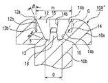
図1および図2は、本発明に係るいじり防止ねじの一実施例を示すものである。すなわち、図1および図2において、参照符号10Aは本発明に係るいじり防止ねじを示し、このいじり防止ねじ10Aの頭部10aは、ナベ型に形成され、その頂部中央にはビット嵌合溝12が設けられている。なお、このビット嵌合溝12は、ねじ頭部10aの中心部において、プラス(+)状に直交する十字溝として構成されている。
【0036】
このビット嵌合溝12は、従来において公知のJIS(日本工業規格)に基づく開口部寸法(m)と溝底部寸法(g)とによって形成されている(図1参照)。すなわち、ビット嵌合溝12の開口端縁部より所要の深さまで、ねじ軸に対し約20〜30°(例えば、26°30′)の傾斜角度βを有する傾斜部15を形成し、この傾斜部15の下縁部よりねじ頭部10aの中心部に指向して、ねじ軸と直角となる水平面に対し約15〜35°の緩傾斜角度αからなるほぼ円錐状の底面13を形成した構成からなる。
【0037】
しかるに、本実施例のいじり防止ねじ10Aにおいては、図1に示すように、前記ビット嵌合溝12の開口端縁部12aにおいて所定深さに亘ってほぼ垂直(実線で示す)ないしは垂直面より内方にそれぞれ断面においてほぼ“く”の字状に凹んだ(破線で示す)壁部12bを形成し、この壁部12bの下縁部12b′よりビット嵌合溝12の交差する中心部方向にほぼ水平に延在する段部14を設ける。さらに、この段部14の端縁部14aからねじ頸部10bの中心部に指向して前述した傾斜部15がそれぞれ形成されると共に、その底部において前述したほぼ円錐状の底面13が形成される。
【0038】
そして、本実施例のいじり防止ねじ10Aにおいては、図1および図2に示すように、前記段部14を形成したビット嵌合溝12の開口端縁部12aと同一の直径寸法により、前記段部14を残して、前記傾斜部15と連接し前記底面13に至る逆円錐台形穴部16を形成することを特徴とする。
【0039】
このように構成した本実施例のいじり防止ねじ10Aにおいては、図1および図2に示すように、それぞれ隣接するビット嵌合溝12において、それぞれ適宜の抜きテーパを有するほぼ垂直な前記段部14の側壁部14bが形成される。従って、この段部14の側壁部14bは、後述するドライバービット20の翼部22の側壁部22bと当接係合して、円滑なねじ締め作業を達成することができるものである。
【0040】
従って、このように構成した本実施例のいじり防止ねじ10Aによれば、ねじ頭部10aのビット嵌合溝12の端縁部に、ほぼ垂直(実線で示す)ないしは凹んだ(破線で示す)壁部12bと段部14とを設けると共に、前記ビット嵌合溝12の開口端縁部12aより前記段部14を残し前記傾斜部15と連接して前記底面13に至る逆円錐台形穴部16を形成することにより、従来のプラス型ドライバーとの結合に際しては、前記逆円錐台形穴部16内において空転させられ、その結合を阻止していじり防止効果を有効に発揮することができる。
【0041】
(いじり防止ねじの構成例1b)
また、本実施例のいじり防止ねじ10Aにおいては、図3および図4に示すように、前記ビット嵌合溝12の開口端縁部12aより前記段部14を残し前記傾斜部15と連接して前記底面13に至る逆円錐台形穴部16を形成すると共に、前記底面13の中心部よりビット嵌合溝12の段部14に達する位置まで突出する突起部18を設けた構成からなるいじり防止ねじ10A′とすることができる。その他の構成は、前記図1および図2に示す実施例のいじり防止ねじ14Aと同じであり、同一の構成部分には同一の参照符号を付して、その詳細な説明は省略する。
【0042】
このように構成した、本実施例のいじり防止ねじ10A′によれば、前記逆円錐台形穴部16の底面13の中心部より、ビット嵌合溝12の段部に達する位置まで突出する突起部18を形成することにより、従来のマイナス型ドライバーとの結合に際しては、前記段部14への嵌合が阻止されて、前記逆円錐台形穴部16内において空転させられ、前記と同様にしていじり防止効果を有効に発揮することができる。
【0043】
実施例2
(いじり防止ねじの構成例2a)
図5は、本発明に係るいじり防止ねじの別の実施例を示すものである。すなわち、図5において、本実施例のいじり防止ねじ10Bは、ねじ頭部10aを、サラ型に形成したものである。そして、本実施例のいじり防止ねじ10Bのねじ頭部10aに設けたビット嵌合溝12の構成は、前述した図1および図2に示す実施例のいじり防止ねじ10Aのねじ頭部10a(ナベ型に形成したもの)に設けたビット嵌合溝12と同一である。そこで、同一の構成部分には同一の参照符号を付して、その詳細な説明は省略する。従って、本実施例のいじり防止ねじ10Bにおいても、前記実施例のいじり防止ねじ10Aと全く同様の作用および効果を発揮させることができる。
【0044】
(いじり防止ねじの構成例2b)
図6は、図5に示すいじり防止ねじ10Bについて、前述した実施例1の図3および図4に示す構成と同様に、前記ビット嵌合溝12の底面13に至る逆円錐台形穴部16を形成すると共に、前記底面13の中心部よりビット嵌合溝12の段部14に達する位置まで突出する突起部18を設けた構成からなるいじり防止ねじ10B′を示すものである。その他の構成は、前記図5に示す実施例のいじり防止ねじ10Bと同じであり、同一の構成部分には同一の参照符号を付して、その詳細な説明は省略する。従って、このように構成したいじり防止ねじ10B′においても、前記実施例1のいじり防止ねじ10A′と全く同様の作用および効果を発揮させることができる。
【0045】
実施例3
(いじり防止ねじの構成例3a)
図7は、本発明に係るいじり防止ねじのさらに別の実施例を示すものであって、ねじ頭部10aに形成するビット嵌合溝12の変形例を示すものである。なお、説明の便宜上、前記図1および図2に示す実施例のいじり防止ねじ10Aと、同一の構成部分については同一の参照符号を付して、その詳細な説明は省略する。すなわち、図7において、本実施例のいじり防止ねじ10Cは、ビット嵌合溝12の相対する段部14の側壁部14bにおいて、ねじ頭部10aの中心部から半径方向外方に指向して、溝幅がほぼ末広がり状の溝部14cとなるように構成したものである。その他の構成は、基本的に前記図1および図2に示す実施例のいじり防止ねじ10Aと同じである。
【0046】
従って、本実施例のいじり防止ねじ10Cによれば、前記末広がり状の溝部14cを形成することにより、隣接する各溝の対向する側壁部14bの開口角度γを直角(90°)より若干鋭角となるように設定して、後述するドライバービット20との組合せにおいて、前述した実施例と同様に、いじり防止ねじ10Cのビット嵌合溝12からのカムアウト現象を有効に防止することができる。
【0047】
(いじり防止ねじの構成例3b)
図8は、図7に示すいじり防止ねじ10Cについて、前述した実施例2の図6に示す構成と同様に、前記ビット嵌合溝12の底面13に至る逆円錐台形穴部16を形成すると共に、前記底面13の中心部よりビット嵌合溝12の段部14に達する位置まで突出する突起部18を設けた構成からなるいじり防止ねじ10C′を示すものである。その他の構成は、前記図7に示す実施例のいじり防止ねじ10Cと同じであり、同一の構成部分には同一の参照符号を付して、その詳細な説明は省略する。従って、このように構成したいじり防止ねじ10C′においても、前記実施例1のいじり防止ねじ10A′と全く同様の作用および効果を発揮させることができる。
【0048】
実施例4
(いじり防止ねじの構成例4a)
図9は、本発明に係るいじり防止ねじのねじ頭部10aに形成するビット嵌合溝12のさらに別の変形例を示すものである。なお、説明の便宜上、前記図1および図2に示す実施例のいじり防止ねじ10Aと、同一の構成部分については同一の参照符号を付して、その詳細な説明は省略する。すなわち、図9において、本実施例のいじり防止ねじ10Dは、前記図1および図2に示す実施例のいじり防止ねじ10Aにおけるビット嵌合溝12の十字溝に代えて、ねじ頭部10aの中心部から三方向に分岐した三方溝からなるビット嵌合溝12′を構成したものである。
【0049】
この三方溝からなるビット嵌合溝12′の構成においては、前述した図1および図2に示す実施例のいじり防止ねじ10Aのビット嵌合溝12と基本的に同じであり、単に溝数が相違するだけで、その内部構成は全く同じである。従って、このように構成した本実施例のいじり防止ねじ10Dに対しては、従来のプラス型ドライバーやマイナス型ドライバーの変形や改造も困難となり、より一層いじり防止効果を高めることが可能となる利点がある。
【0050】
(いじり防止ねじの構成例4b)
図10は、図9に示すいじり防止ねじ10Dについて、前述した実施例2の図6に示す構成と同様に、前記ビット嵌合溝12の底面13に至る逆円錐台形穴部16を形成すると共に、前記底面13の中心部よりビット嵌合溝12の段部14に達する位置まで突出する突起部18を設けた構成からなるいじり防止ねじ10D′を示すものである。その他の構成は、前記図9に示す実施例のいじり防止ねじ10Dと同じであり、同一の構成部分には同一の参照符号を付して、その詳細な説明は省略する。従って、このように構成したいじり防止ねじ10D′においても、前記実施例1のいじり防止ねじ10A′と全く同様の作用および効果を発揮させることができる。
【0051】
以上、本発明に係るいじり防止ねじ10の好適な実施例についてそれぞれ説明したが、本発明に係るいじり防止ねじ10のビット嵌合溝12は、従来において公知のJIS(日本工業規格)に基づく開口部寸法【m】と溝底部寸法(g)とに基づくものであり、ビット嵌合溝12の中位部にそれぞれほぼ水平に延在する段部14を設け、前記段部14を形成したビット嵌合溝12の開口端縁部12aと同一の直径寸法により、前記段部14を残し傾斜部15と連接して底面13に至る逆円錐台形穴部16を形成することにより、従来のプラス型ドライバーのビット先端部との結合を確実に阻止し、いじり防止効果を十分に発揮させることができる。さらに、前記逆円錐台形穴部16を形成すると共に、前記底面13の中心部よりビット嵌合溝12の前記段部14に達する位置まで突出する突起部18を設けることによって、従来のプラス型ドライバーのみならずマイナス型ドライバーのビット先端部との結合をも確実に阻止し、いじり防止効果をより有効に発揮させることができる。
【0052】
また、本発明に係るいじり防止ねじ10は、後述する構成からなるドライバービット20を適用することにより、ドライバービット20がいじり防止ねじ10に対して、ビット嵌合溝12の中位部にそれぞれ断面においてほぼ直角に形成した段部14の側壁部14bと係合して、回転駆動力を与えるのに十分な面積(以下、駆動面積という)を保持することができると共に、ドライバービット20のカムアウト現象を確実に防止し、いじり防止ねじ10に対するバランスのとれたトルク伝達を達成して、適正なねじ締め作業を行うことができる。
【0053】
しかも、前記逆円錐台形孔部16ないし傾斜部15の傾斜角度βの設定が、ねじ頭部10aをナベ型(図2参照)およびサラ型(図3参照)に形成したいじり防止ねじ10A、10Bにおいて、ビット嵌合溝12の形成に際して、ねじ頭部10aとねじ頸部10bとの境界部の肉厚を、適正に保持することができるため、ねじ締め作業に際してのねじの強度を十分に高めることができる利点を有している。また、このような形状からなるビット嵌合溝12は、後述するヘッダーパンチ30により簡便かつ容易に形成することができる。
【0054】
実施例5
(ドライバービットの構成例1a)
図11および図12の(a)、(b)は、本発明に係るいじり防止ねじ10A、10Bに適用するドライバービット20の一実施例を示すものである。本実施例に係るドライバービット20は、前記いじり防止ねじ10A、10Bのビット嵌合溝12に嵌合し、このビット嵌合溝12の端縁部に形成したほぼ垂直(実線で示す)ないしは凹んだ(破線で示す)壁部12bに対応し、かつ前記段部14に係合するように、ほぼ直角に延在する端縁部22aを有する翼部22をそれぞれ備える。また、本実施例のドライバービット20は、前記各翼部22の先端部を前記ビット嵌合溝12の段部14の端縁部14aよりねじ頸部10bの中心部に指向して延在形成された逆円錐台形穴部16ないし傾斜部15の形状に適合するように、それぞれ延在させた突出部24が形成される。
【0055】
このように構成される本実施例に係るドライバービット20においては、図11および図12の(a)、(b)に示すように、前記各翼部22ないし突出部24の両側面に形成される多少のテーパは許容し得るほぼ垂直な側壁部22bが形成される。従って、この翼部22の側壁部22bは、前記いじり防止ねじ10A、10Bの段部14の側壁部14bと当接係合して、円滑なねじ締め作業を達成することができると共に、カムアウト現象を容易かつ確実に防止することができる。
【0056】
(ドライバービットの構成例1b)
図13および図14の(a)、(b)は、本発明に係るいじり防止ねじ10A′、10B′に適用するドライバービット20′の変形例を示すものである。すなわち、本実施例においては、前記突出部24の先端中央に、前記ビット嵌合溝12に設けられた突起部18を案内挿通し得る凹部26を形成したことを特徴とするものである。その他の構成は、前述した図11および図12の(a)、(b)に示すドライバービット20の構成と同じであり、従って、同一の構成部分には同一の参照符号を付し、その詳細な説明は省略する。
【0057】
A.本発明のいじり防止ねじと本実施例のドライバービットとの結合例1
図15は、本発明に係るいじり防止ねじ10A(10B)と本実施例のドライバービット20〔図11、図12の(a)、(b)参照〕との結合状態を示す要部断面側面図である。すなわち、図15から明らかなように、ドライバービット20の翼部22に形成した端縁部22aおよび突出部24が、いじり防止ねじ10A(10B)のビット嵌合溝12に設けた段部14にそれぞれ係合ないし嵌合し、さらにドライバービット20の前記翼部22の側壁部22bが、いじり防止ねじ10A(10B)の前記段部の側壁部14bに当接して、ドライバービット20を回動することにより、いじり防止ねじ10に対して所定のトルク伝達を行い、適正なねじ締め作業を達成することができる。
【0058】
B.本発明のいじり防止ねじと本実施例のドライバービットとの結合例2
図16は、本発明に係るいじり防止ねじ10A′(10B′)と本実施例のドライバービット20′〔図13、図14の(a)、(b)参照〕との結合状態を示す要部断面側面図である。すなわち、図16から明らかなように、ドライバービット20′の翼部22に形成した端縁部22aおよび突出部24の先端中央に設けた凹部26が、いじり防止ねじ10A′(10B′)のビット嵌合溝12に設けた段部14および突起部18にそれぞれ係合ないし嵌合し、さらにドライバービット20の前記翼部22の側壁部22bが、いじり防止ねじ10A′(10B′)の前記段部の側壁部14bに当接して、ドライバービット20′を回動することにより、いじり防止ねじ10A′(10B′)に対して所定のトルク伝達を行い、適正なねじ締め作業を達成することができる。
【0059】
なお、前述した実施例1および実施例2によるいじり防止ねじ10A、10Bと前記ドライバービット20との組合せ(図15参照)、およびいじり防止ねじ10A′、10B′と前記ドライバービット20′との組合せ(図16参照)において、いじり防止ねじ10A、10Bおよび10A′、10B′のビット嵌合溝12の端縁部の壁部12bを凹んだ状態に形成した(破線で示す)場合には、ドライバービット20および20′との結合に際し、その垂直面より凹んだ部分が常に空隙部Gとして存在することから、ビット嵌合溝12内へ塵埃や異物等を押し込むことができ、これによりドライバービット20および20′のビット先端部と、いじり防止ねじ10A、10Bおよび10A′、10B′のビット嵌合溝12との係合ないし嵌合を、常に容易かつ確実となる利点が得られる(図1ないし図10参照)。
【0060】
なお、前述した実施例3および実施例4によるいじり防止ねじ10Cおよび10C′、10Dおよび10D′にそれぞれ適応するドライバービット20および20′としては、前記いじり防止ねじ10Cおよび10C′、10Dおよび10D′のビット嵌合溝12の形状にそれぞれ適合するように、各翼部22ないし突出部24を適宜設計変更することにより、ドライバービット20および20′との適正な結合ないし係合を達成することができる。
【0061】
C.従来のプラス型ドライバーとの結合例1
図17は、本発明に係るいじり防止ねじ10A(10B)と従来のプラス型ドライバー28との結合について示した要部断面側面図である。すなわち、図17から明らかなように、プラス型ドライバー28のビット先端部28aは、いじり防止ねじ10A(10B)のビット嵌合溝12に設けられた逆円錐台形穴部16に遊嵌するのみであり、その係合は阻止され、いじり防止効果が発揮される。
【0062】
D.従来のプラス型ドライバーとの結合例2
図18は、本発明に係るいじり防止ねじ10A′(10B′)と従来のプラス型ドライバー28との結合について示した要部断面側面図である。すなわち、図18から明らかなように、プラス型ドライバー28のビット先端部28aは、いじり防止ねじ10A′(10B′)のビット嵌合溝12に設けられた逆円錐台形穴部16に遊嵌すると共に突起部18に突き当たり、係合が阻止されていじり防止効果が発揮される。この場合、プラス型ドライバー28において、前記ビット先端部28aに前記いじり防止ねじ10A′(10B′)の突起部18を案内挿通し得る凹部を形成したとしても、前記ビット嵌合溝12に設けた段部14との係合は不可能であり、いじり防止効果を維持することができる。
【0063】
E.従来のマイナス型ドライバーとの結合例3
図19は、本発明に係るいじり防止ねじ10A′(10B′)と従来のマイナス型ドライバー29との結合について示した要部断面側面図である。すなわち、図19から明らかなように、マイナス型ドライバー29のビット先端部29aは、いじり防止ねじ10A′(10B′)のビット嵌合溝12に設けられた段部14と係合させようとした場合、突起部18に突き当たり、係合が阻止されていじり防止効果が発揮される。そして、この場合、マイナス型ドライバー29において、前記ビット先端部29aに前記いじり防止ねじ10A′(10B′)の突起部18を案内挿通し得る切欠部を形成して、前記ビット嵌合溝12に設けた段部14と係合可能であっても、ビット先端部29aの強度が損なわれて、回動する際にはビット先端部29aが破損してしまい、結局いじり防止ねじ10A′(10B′)との係合が阻止されていじり防止効果を維持することができる。
【0064】
実施例6
(いじり防止ねじ製造用ヘッダーパンチの構成例1a)
図20および図21の(a)、(b)は、前記図1および図2に示す実施例1のいじり防止ねじ10Aを製造するためのヘッダーパンチ30の一実施例を示すものである。本実施例に係るヘッダーパンチ30は、図1に示すいじり防止ねじ10Aのねじ頭部10aおよびそのビット嵌合溝12を押し抜き成形加工するものである。そして、本実施例のヘッダーパンチ30は、ねじ頭部10aの前記ビット嵌合溝12の端縁部に垂直ないしは凹んだ壁部12bと段部14とを形成するためのほぼ直角な端縁部34aを有する突起片34をそれぞれ備え、前記ビット嵌合溝12においてその中心部における逆円錐台形穴部16ないし傾斜部15を形成すると共にほぼ円錐状の底面13を形成するための円錐突部36が設けられる。
【0065】
従って、このように構成される本実施例に係るヘッダーパンチ30を使用して、いじり防止ねじ10Aのねじ頭部10aにおけるビット嵌合溝12を押し抜き成形加工する場合には、前記ヘッダーパンチ30の突起片34が、いじり防止ねじ10を形成する金属線材のねじ頭部形成部分にパンチングさせることにより、その衝撃によってビット嵌合溝12を形成する金属線材の一部が、圧縮ないし伸長変位することによって、前記ビット嵌合溝12の端縁部において前述した通りの垂直ないしは凹んだ壁部12bと段部14とを同時にかつ容易に成形加工することができる。
【0066】
(いじり防止ねじ製造用ヘッダーパンチの構成例1b)
図22および図23の(a)、(b)は、前記図3および図4に示す実施例1のいじり防止ねじ10A′を製造するためのヘッダーパンチ30′の変形例を示すものである。すなわち、本実施例においては、前記円錐突部36の先端中央に、前記ビット嵌合溝12の突起部18を形成するための孔部38を設けたことを特徴とするものである。その他の構成は、前述した図20および図21の(a)、(b)に示すヘッダーパンチ30の構成と同じであり、同一の構成部分には同一の参照符号を付して、その詳細な説明は省略する。
【0067】
なお、前述した実施例によるいじり防止ねじ10Bおよび10B′、10Cおよび10C′、10Dおよび10D′をそれぞれ製造するためのヘッダーパンチ30および30′としては、前記いじり防止ねじ、10Bおよび10B′、10Cおよび10C′、10Dおよび10D′のビット嵌合溝12の形状にそれぞれ適合するように、各突起片34を適宜設計変更することにより、それぞれいじり防止ねじの製造を容易に達成することができる。
【0068】
【発明の効果】
以上、本発明に係るいじり防止ねじの好適な実施例についてそれぞれ説明したが、本発明に係るいじり防止ねじは、従来の一般的なねじの構造を基礎として、ビット嵌合溝の形状を改善することにより、簡単な構成で従来の一般的なドライバーによる結合を防止して、ねじ締め作業を確実に阻止することができるいじり防止ねじを容易に得ることができる。従って、本発明に係るいじり防止ねじは、比較的簡単な構成からなるヘッダーパンチを使用して、容易かつ低コストに製造することができる。
【0069】
また、本発明のいじり防止ねじに適用するドライバービットは、従来のドライバービットの構造を基礎として、ビット先端部の形状を改善することにより、前記いじり防止ねじとの結合を簡便かつ迅速に達成し得ると共に、ねじ締め作業に際してのカムアウト現象を確実に防止することができる。
【図面の簡単な説明】
【図1】本発明に係るいじり防止ねじの一実施例として頭部をナベ型に構成したいじり防止ねじの要部断面側面図である。
【図2】図1に示す本発明に係るいじり防止ねじの頭部平面図である。
【図3】図1に示す本発明に係るいじり防止ねじの変形例を示す要部断面側面図である。
【図4】図3に示す本発明に係るいじり防止ねじの頭部平面図である。
【図5】本発明に係るいじり防止ねじの別の実施例として頭部をサラ型に構成したいじり防止ねじの要部断面側面図である。
【図6】図5に示す本発明に係るいじり防止ねじの変形例を示す要部断面側面図である。
【図7】本発明に係るいじり防止ねじのビット嵌合溝の別の実施例を示すいじり防止ねじの頭部平面図である。
【図8】図7に示す本発明に係るいじり防止ねじの変形例を示すいじり防止ねじの頭部平面図である。
【図9】本発明に係るいじり防止ねじのビット嵌合溝のさらに別の実施例を示すいじり防止ねじの頭部平面図である。
【図10】図9に示す本発明に係るいじり防止ねじの変形例を示すいじり防止ねじの頭部平面図である。
【図11】図1に示す本発明に係るいじり防止ねじと適合するビット先端部を備えた本発明に係るドライバービットの一実施例を示す要部拡大側面図である。
【図12】(a)は図11に示す本発明に係るドライバービットのXII−XII線要部断面図、(b)は図11に示す本発明に係るドライバービットのビット先端部の端面図である。
【図13】図3に示す本発明に係るいじり防止ねじと適合するビット先端部を備えた本発明に係るドライバービットの変形例を示す要部拡大側面図である。
【図14】(a)は図13に示す本発明に係るドライバービットのXIV−XIV線要部断面図、(b)は図13に示す本発明に係るドライバービットのビット先端部の端面図である。
【図15】図11に示す本発明に係るドライバービットと図1に示す本発明に係るいじり防止ねじとの結合状態を示す要部断面側面図である。
【図16】図13に示す本発明に係るドライバービットと図3に示す本発明に係るいじり防止ねじとの結合状態を示す要部断面側面図である。
【図17】従来のプラス型ドライバービットと図1に示す本発明に係るいじり防止ねじとの結合について示す要部断面側面図である。
【図18】従来のプラス型ドライバービットと図3に示す本発明に係るいじり防止ねじとの結合について示す要部断面側面図である。
【図19】従来のマイナス型ドライバービットと図3に示す本発明に係るいじり防止ねじとの結合について示す要部断面側面図である。
【図20】図1に示す本発明に係るいじり防止ねじの頭部およびビット嵌合溝を成形するための本発明に係るいじり防止ねじ製造用ヘッダーパンチの要部側面図である。
【図21】(a)は図20に示す本発明に係るヘッダーパンチのXXI−XXI線要部断面図、(b)は図20に示す本発明に係るヘッダーパンチの先端側の端面図である。
【図22】図3に示す本発明に係るいじり防止ねじの頭部およびビット嵌合溝を成形するための本発明に係るいじり防止ねじ製造用ヘッダーパンチの要部側面図である。
【図23】(a)は図22に示す本発明に係るヘッダーパンチのXXIII −XXIII 線要部断面図、(b)は図22に示す本発明に係るヘッダーパンチの先端側の端面図である。
【符号の説明】
10A、10A′ いじり防止ねじ(ナベ型)
10B、10B′ いじり防止ねじ(サラ型)
10C、10C′ いじり防止ねじ(末広がり状の溝型)
10D、10D′ いじり防止ねじ(三方溝型)
10a ねじ頭部
10b ねじ頸部
12 ビット嵌合溝(十字溝)
12′ ビット嵌合溝(三方溝)
12a 開口端縁部
12b 垂直ないし凹んだ壁部
12b′ 壁部の下縁部
13 底面
14 段部
14a 段部の端縁部
14b 段部の側壁部
14c 末広がり状の溝部
15 傾斜部
16 逆円錐台形穴部
18 突起部
20、20′ ドライバービット
22 翼部
22a 端縁部
22b 翼部の側壁部
24 突出部
26 凹部
28 プラス型ドライバー
28a ビット先端部
29 マイナス型ドライバー
29a ビット先端部
30、30′ ヘッダーパンチ
34 突起片
34a 端縁部
36 円錐突部
38 孔部[0001]
BACKGROUND OF THE INVENTION
The present invention is supported by a commercially available and commonly used screwdriver in which the bit tip is formed into a plus type and a minus type, a screwdriver in which the bit tip is formed in a polygonal shape such as a hexagon (screwdriver), etc. When connecting a bit fitting groove with a shape to the screw formed on the screw head, it is not possible to fit the bit tip of the corresponding driver to the bit fitting groove formed on the screw head. The present invention relates to an anti-twisting screw configured to inhibit the tightening and removing operation of the screw, a driver bit that can be suitably used for the screw, and a header punch for manufacturing the anti-twisting screw.
[0002]
[Prior art]
Conventionally, when a screw is unnecessarily removed by a third party in a device that is assembled and assembled by attaching various parts by screw attachment, the device is disassembled or parts are separated, and the adjustment points It is difficult to restore the function of the device to its original state due to the exposure of hazardous locations.BecomeIn addition, there are difficulties that lead to the occurrence of emergency accidents. From this point of view,InVarious tamper-preventing screws that cannot be easily tightened or removed by some commercially available drivers (screwdrivers) have been proposed.
[0003]
As this type of anti-twisting screw, for example, a plurality of fan-shaped projections equally divided by a straight line in the radial direction are formed on the upper surface of a circular head, and the surface is a unidirectional rotating screw surface, so that a normal driver is engaged. It has been proposed that it can be tightened using an upright surface formed on one end face of the fan-shaped projection only when a special dedicated tool is used (special No. 2000-220619).
[0004]
The dedicated tool for the tamper-preventing screw includes a circular recess capable of fitting the circular head of the tamper-preventing screw at the tip of the tool body, and the tamper-preventing screw is provided inside the circular recess. In this configuration, a plurality of fan-shaped projections having a shape corresponding to the relationship between the male head and the female head are formed.
[0005]
Also, special bolts and special nuts that cannot be easily rotated by commonly used general tools, and therefore are not likely to be easily rotated by a third party, and also those special bolts and special nuts. The fastening device comprised by these is proposed (Unexamined-Japanese-Patent No. 11-270529).
[0006]
The special bolt according to this proposal has a truncated cone shape in which the outer diameter is gradually reduced toward the tip side away from the shaft portion at the end portion on the opposite side of the shaft portion provided with a thread groove on one end portion. The head of the head is provided concentrically with the shaft, and an engaging recess having a regular pentagonal cross section with a corner formed in an arc shape is provided at the tip of the head. In the engaging recess, a frustoconical protrusion having an outer diameter that gradually decreases toward the distal end is provided.
[0007]
Therefore, since the special bolt configured in this way has a truncated cone shape with a small diameter as its head becomes the tip side, even when trying to engage a normal tool such as a wrench or spanner, Without being engaged with the head, the tip can easily be pulled out. That is, the effect of preventing messing with a third party can be effectively exhibited.
[0008]
The special tool that can be rotated by being engaged with the special bolt has a hexagonal columnar tool main body and a head provided at one end of the tool main body. The part has a regular pentagonal columnar shape with an outer peripheral surface aligned with the inner peripheral surface of the engaging recess in the head of the special bolt, and its axial center part is fitted to the protrusion on the head of the special bolt. A through-hole having an inner diameter to be obtained is provided, the through-hole has a constant inner diameter over the entire length of the special tool, and the tool main body portion is configured to penetrate the axial center portion. Therefore, the special tool can fit the head portion into the engagement recess of the special bolt, and thereby the special bolt can be easily rotated.
[0009]
However, in the conventional combination of a general screw and a driver bit, a cross groove is provided in the screw head, and each of these cross grooves is directed from the opening edge to the center of the screw neck, and each has a fixed shape. The inclined portion extends and the bottom portion has a substantially conical bottom surface that is gently inclined. On the other hand, the conventional driver bit is provided with a tip wing portion that fits into the cross groove of the screw, and an inclination that extends from the opening edge of the cross groove toward the center of the screw neck portion. Each of the protrusions extends to match the shape of the part.
[0010]
According to the combination of the conventional screw and the driver bit having such a configuration, the tapered side wall portion formed on each tip wing portion of the driver bit is brought into contact with the tapered side wall portion formed in the cross groove of the screw. Therefore, when the driver bit is rotated in a predetermined direction, the contact state between the driver bit and the cross groove becomes a taper contact on the entire surface, so that the tip of the driver bit is at the inclined portion of the cross groove. A so-called come-out phenomenon occurs that attempts to jump outward along the inclined surface. Therefore, not only the opening edge of the cross groove of the screw is damaged with this cam-out phenomenon, but also the cam-out phenomenon becomes more frequent due to the expansion of the damage, making it difficult to tighten the screw. There is.
[0011]
From this point of view, the present applicant has first provided a bit fitting groove made of a cross groove in the screw head, and is directed from the edge of the bit fitting groove toward the center of the screw neck. In addition, a screw having a substantially conical bottom surface at the crossing center portion thereof is provided with a step portion substantially perpendicular to the cross section at the middle portion of the inclined portion of the bit fitting groove. By configuring so that a part of the driver bit is engaged, the cam bit phenomenon of the driver bit can be surely prevented, the strength of the screw can be increased and the breakage thereof can be significantly reduced, and the balance with respect to the screw can be reduced. Successful development of a new screw capable of achieving excellent torque transmission (JP-A-9-177743, JP-A-11-236910, JP-A-11-31226) JP 2000-108043 Patent Publication).
[0012]
In this case, the driver bit is provided with a wing portion having a substantially right end edge portion engaged with a step portion formed in the middle portion of the bit fitting groove of the screw, and each wing portion includes: By forming protrusions each extending so as to fit the shape of the groove extending from the stepped portion, it was possible to obtain a configuration most suitable for the bit fitting groove of the screw. .
[0013]
Therefore, according to the combination of the screw and the driver bit having the above-described configuration, particularly when applied to a small and light precision machine screw, the bit fitting grooveFormation,It can be easily performed without reducing the screw strength, reliably prevents the driver bit cam-out phenomenon, and provides balanced torque transmission to the screw to always achieve a proper and safe screw tightening operation. I understood.
[0014]
[Problems to be solved by the invention]
However, the conventional tamper-preventing screw described above is extremely different in the configuration of the engaging portion of the screw head and the bit tip portion of the screw driver that engages with the conventional screw / driver combination. Since the screw and the driver bit are manufactured in a complicated and special shape, problems such as an increase in manufacturing cost as well as a lot of labor are required. Further, in the conventional combination of the anti-twisting screw and the driver bit, no consideration is given to the cam-out phenomenon as described above. However, in the tightening and removing operation of the screw by the combination of the anti-twisting screw and the driver proposed, there is no guarantee that the screw can be smoothly achieved without coming out, but there is a drawback that the shape tends to cause a cam-out phenomenon.
[0015]
Therefore, as a result of intensive research and examination, the present inventor has provided a bit fitting groove made of a cross groove or the like on the screw head, and the opening end edge of the bit fitting groove is located at the center of the screw neck. In addition to forming an inclined part having a required inclination angle, the intermediate part of the inclined partStep that extends almost horizontallyAnd forming a screw having a substantially conical bottom surface at the intersection center of the inclined portion.With the same diameter dimension as the opening edge of the bit fitting groove forming the stepped portionIn the conventional general plus-type screwdriver, the inverted cone is formed by forming a frusto-conical screw which is formed by forming an inverted frustoconical hole portion that is connected to the inclined portion and leaves the stepped portion and reaches the bottom surface. Due to the presence of the trapezoidal hole, the present inventors succeeded in obtaining a new anti-tampering screw that can reliably prevent the tightening and removal of the screw.
[0016]
On the other hand, for the tamper-preventing screw having the above-described configuration, a wing portion having a substantially perpendicular end edge portion engaged with a step portion formed in the middle portion of the inclined portion of the bit fitting groove of the tamper-preventing screw. Protrusions that are respectively provided and extended so as to conform to the shape of an inverted frustoconical hole or inclined portion that extends from the stepped portion toward the center of the screw neck portion. By forming a screwdriver bit that is formed with a portion, it is easy and fast, easily and reliably, without any cam-out phenomenon from the screw bit fitting groove at the time of tightening and removing the tamper-proof screw. I found out that I can achieve it.
[0017]
When manufacturing the tamper-proof screw having the above-described configuration, a substantially perpendicular end edge for forming a wall part and a step part perpendicular to or recessed from the end edge part of the bit fitting groove of the screw head is provided. A header punch, each having a projecting piece having an inverted frustoconical hole or inclined portion in the center of the bit fitting groove, and a conical protrusion for forming a substantially conical bottom surface. It has been found that the construction of the above-described tamper-preventing screw can be easily and easily achieved at a low cost.
[0018]
As an alternative, the tamper-preventing screw has an inverted frustoconical hole that reaches the bottom surface with the stepped portion being connected to the inclined portion, with the opening edge of the bit fitting groove of the screw having the maximum diameter. And the stepped portion of the bit fitting groove from the center of the bottom surfacePosition to reachBy providing a projecting portion that protrudes to the end, even with a conventional general plus-type screwdriver and minus-type screwdriver, the screw can be tightened and removed due to the presence of the inverted frustoconical hole and the projection. It was confirmed that it can be reliably prevented.
[0019]
In this case, as a driver bit adapted to the tamper-proof screw, the shape of an inverted frustoconical hole or inclined portion in which the tip of each wing extends from the step toward the center of the screw neck. In addition, a projecting portion extending so as to be adapted to each of the projecting portions is formed, and a concave portion that guides and inserts the projecting portion is provided in the center of the tip of the projecting portion. At that time, it was confirmed that it can be easily and reliably achieved easily and quickly without causing a cam-out phenomenon from the bit fitting groove of the screw.
[0020]
And as a header punch for manufacturing the tamper-proof screw, an inverted frustoconical hole or inclined portion in the center of the bit fitting groove is formed, and a conical protrusion for forming a substantially conical bottom is formed. By providing a hole for forming a protrusion at the center of the tip of the conical protrusion, the tamper-proofing screw can be manufactured easily and easily at low cost. confirmed.
[0021]
Accordingly, an object of the present invention is to improve the shape of the bit fitting groove based on the structure of a conventional general screw, thereby preventing the connection by a conventional general driver with a simple configuration and tightening the screw. Based on the structure of the conventional screwdriver bit and the tamper-proof screw that can reliably prevent the work, and improving the shape of the bit tip, it can be easily and quickly coupled with the tamper-proof screw. In addition, there is provided a screwdriver bit that can reliably prevent a cam-out phenomenon during screw tightening, and a tamper-proof screw manufacturing header punch that can be manufactured easily and easily at a low cost. It is to provide.
[0022]
[Means for Solving the Problems]
In order to achieve the above object, the tamper-proof screw according to claim 1 of the present invention is provided with a bit fitting groove formed as a cross groove or a three-way groove on the screw head and fitted with a blade portion of a driver bit, respectively. And forming an inclined part having a required inclination angle from the opening edge of the bit fitting groove toward the center of the screw neck, and extending from the opening edge of the inclined part to the middle part. A vertical wall portion is formed over a predetermined depth and a step portion extending substantially horizontally from the lower edge portion of the wall portion toward the center portion where the bit fitting groove intersects is provided. The intersection center is formed as a substantially conical bottom,An opening edge portion of the bit fitting groove formed so as to be connected to a circumferential direction at the same inclination angle as that of the inclined portion and to reach the bottom surface from the opening edge portion of the bit fitting groove. Has an open edge of the same diameter asAn inverted frustoconical hole is provided.
[0023]
According to a second aspect of the present invention, the tamper-preventing screw is provided with a bit fitting groove formed as a cross groove or a three-way groove on the screw head to be fitted to the wing portion of the driver bit, and the opening of the bit fitting groove. An inclined portion having a required inclination angle is formed from the end edge portion toward the center of the screw neck portion, and is perpendicular to a predetermined depth from the opening edge portion to the middle portion of the inclined portion. A step portion extending substantially horizontally from the lower edge portion of the wall portion toward the center portion where the bit fitting groove intersects is provided, and the intersecting center portion of the inclined portion is substantially conical. Formed as the bottom,An opening edge portion of the bit fitting groove formed so as to be connected to a circumferential direction at the same inclination angle as that of the inclined portion and to reach the bottom surface from the opening edge portion of the bit fitting groove. Has an open edge of the same diameter asAn inverted frustoconical hole is provided, and a protrusion protruding from the center of the bottom surface to a position reaching the stepped portion of the bit fitting groove is provided.
[0024]
A tamper-proof screw according to claim 3 of the present invention is provided.From the opening edge of the bit fitting groove to the bottomThe inclined part and the inverted frustoconical hole part connected to this in the circumferential direction at the same inclination angle are, Formed at an inclination angle of about 20-30 ° with respect to the screw shaft.It is characterized by.
[0025]
The tamper-preventing screw according to claim 4 of the present invention isIn the middle part of the inclined part of the bit fitting grooveBe providedSaid stepIn,From the opening edge of the bit fitting grooveEach over a given depthAgainst the vertical wall that is formedForms a wall recessed inward from the vertical planeCharacterized by.
[0026]
The tamper-proof screw according to claim 5 of the present invention is,The recessed wall portion formed in the vertical wall portion of the stepped portion of the bit fitting groove is configured to be recessed in a substantially “<” shape in cross section..
[0027]
The tamper-proof screw according to claim 6 of the present invention isThe bit fitting groove is formed as a groove having a substantially divergent groove width directed radially outward from the center of the screw head, and the opening angle of the opposing side wall portion of each adjacent groove is a right angle. Configured to be slightly sharperCharacterized by.
[0028]
The tamper-proof screw according to claim 7 of the present invention is, The screw head is a pan-type or a Sara-typeIt is characterized by comprising in the shape consisting of.
[0029]
The combination of the tamper-proof screw and the driver bit according to claim 8 of the present invention is provided with a bit fitting groove formed as a cross groove or a three-way groove on the screw head and fitted to the wing portion of the driver bit, respectively. An inclined part having a required inclination angle is formed from the opening edge of the bit fitting groove toward the center of the screw neck, and a predetermined distance from the opening edge to the middle part of the inclined part. A vertical wall portion is formed over the depth, and a step portion extending substantially horizontally from the lower edge portion of the wall portion toward the center portion where the bit fitting groove intersects is provided, and the intersection center of the inclined portion is provided. The part is formed as a substantially conical bottom,An opening edge portion of the bit fitting groove formed so as to be connected to a circumferential direction at the same inclination angle as that of the inclined portion and to reach the bottom surface from the opening edge portion of the bit fitting groove. Has an open edge of the same diameter asA tamper-proof screw characterized by providing an inverted frustoconical hole;
Each of the wing portions has a substantially right edge that engages with a step portion formed in the middle portion of the bit fitting groove of the tamper-preventing screw, and the tip portion of each wing portion is screwed from the step portion. From a configuration in combination with a driver bit characterized by forming an inverted frustoconical hole extending toward the center of the neck or a projecting portion extending to fit the shape of the inclined portion Become.
[0030]
The combination of the tamper-proofing screw and the driver bit according to claim 9 of the present invention is provided with a bit fitting groove that is formed as a cross groove or a three-way groove on the screw head and is fitted to the blade portion of the driver bit. An inclined part having a required inclination angle is formed from the opening edge of the bit fitting groove toward the center of the screw neck, and a predetermined distance from the opening edge to the middle part of the inclined part. A vertical wall portion is formed over the depth, and a step portion extending substantially horizontally from the lower edge portion of the wall portion toward the center portion where the bit fitting groove intersects is provided, and the intersection center of the inclined portion is provided. The part is formed as a substantially conical bottom,An opening edge portion of the bit fitting groove formed so as to be connected to a circumferential direction at the same inclination angle as that of the inclined portion and to reach the bottom surface from the opening edge portion of the bit fitting groove. Has an open edge of the same diameter asA tamper-proof screw characterized by providing an inverted frustoconical hole and a projection that protrudes from the center of the bottom surface to a position that reaches the stepped portion of the bit fitting groove;
Each of the wing portions has a substantially right edge that engages with a step portion formed in the middle portion of the bit fitting groove of the tamper-preventing screw, and the tip portion of each wing portion is screwed from the step portion. Protrusions are formed to extend to fit the shape of the inverted frustoconical hole or inclined part extending toward the center of the neck, and the protrusion is formed at the center of the tip of the protrusion. It comprises a combination with a driver bit characterized by providing a recess for guiding and inserting.
[0031]
The combination of the tamper-proof screw and the driver bit according to claim 10 of the present invention isThe protrusion at the tip of the bit of the driver bit isAn angle suitable for the inclination angle of the inclined portion of the bit fitting groove of the screwIt is characterized by being formed.
[0032]
A header punch for manufacturing a tamper-proof screw according to claim 11 of the present invention is provided with a bit fitting groove formed as a cross groove or a three-way groove on a screw head and fitted with a blade portion of a driver bit, respectively. An inclined part having a required inclination angle is formed from the opening edge of the bit fitting groove toward the center of the screw neck, and a predetermined distance from the opening edge to the middle part of the inclined part. Forming a vertical wall portion over the entire depth of the wall and providing a step portion extending substantially horizontally from the lower edge portion of the wall portion toward the center portion where the bit fitting groove intersects, The center is formed as a substantially conical bottom,An opening edge portion of the bit fitting groove formed so as to be connected to a circumferential direction at the same inclination angle as that of the inclined portion and to reach the bottom surface from the opening edge portion of the bit fitting groove. Has an open edge of the same diameter asA header punch for manufacturing a tamper-proof screw characterized by providing an inverted frustoconical hole,
Protruding pieces each having a substantially right end edge for forming a step portion having a vertical or recessed wall portion in the bit fitting groove of the screw head, each having an inverted cone in the center portion of the bit fitting groove A trapezoidal hole or inclined portion is formed, and a conical protrusion for forming a substantially conical bottom surface is provided.
[0033]
A header punch for manufacturing a tamper-proof screw according to claim 12 of the present invention is the conical protrusion.A hole for forming the projection is provided in the center of the tip of
[0034]
DETAILED DESCRIPTION OF THE INVENTION
Next, examples of the combination of the tamper-proof screw and the driver bit and the header punch for manufacturing the tamper-proof screw according to the present invention will be described in detail with reference to the accompanying drawings.
[0035]
Example 1
(Tamper prevention screw configuration example 1a)
1 and 2 show an embodiment of the tamper-preventing screw according to the present invention. That is, in FIGS. 1 and 2, reference numeral 10 </ b> A denotes a tamper-proof screw according to the present invention, and a
[0036]
This bit
[0037]
However, in the tamper-preventing
[0038]
In the tamper-preventing
[0039]
Tamper-preventing screw of this embodiment configured in this way10In A, as shown in FIG. 1 and FIG. 2, the
[0040]
Therefore, the tamper-preventing screw of the present embodiment configured in this way10According to A, at the end portion of the bit
[0041]
(Example 1b of tamper-proof screw)
Further, in the tamper-preventing
[0042]
According to the tamper-preventing
[0043]
Example 2
(Tamper prevention screw configuration example 2a)
FIG. 5 shows another embodiment of the tamper-preventing screw according to the present invention. That is, in FIG. 5, the tamper-preventing
[0044]
(Example 2b of tamper-proof screw)
FIG. 6 shows the frusto-conical
[0045]
Example 3
(Tamper prevention screw configuration example 3a)
FIG. 7 shows still another embodiment of the tamper-preventing screw according to the present invention, and shows a modification of the bit
[0046]
Therefore, according to the tamper-preventing
[0047]
(Configuration example 3b of tamper-proof screw)
FIG. 8 shows an
[0048]
Example 4
(Tamper prevention screw configuration example 4a)
FIG. 9 shows still another modified example of the bit
[0049]
The configuration of the bit fitting groove 12 'formed of this three-way groove is basically the same as the bit
[0050]
(Tamper prevention screw configuration example 4b)
FIG. 10 shows an
[0051]
Although the preferred embodiments of the tamper-preventing screw 10 according to the present invention have been described above, the bit
[0052]
Further, the tamper-preventing screw 10 according to the present invention is applied to a
[0053]
In addition, the setting of the inclination angle β of the inverted
[0054]
Example 5
(Driver bit configuration example 1a)
FIGS. 11 and 12 (a) and 12 (b) show an embodiment of the
[0055]
In the
[0056]
(Driver bit configuration example 1b)
FIGS. 13 and 14 (a) and 14 (b) show a modification of the driver bit 20 'applied to the tamper-preventing
[0057]
A.Example 1 of coupling of the tamper-preventing screw of the present invention and the driver bit of the present embodiment
FIG. 15 is a cross-sectional side view of an essential part showing a coupling state between the tamper-preventing
[0058]
B.Example 2 of coupling the tamper-proofing screw of the present invention and the driver bit of the present embodiment
FIG. 16 is a main portion showing a coupling state between the tamper-preventing
[0059]
It should be noted that the tamper-preventing
[0060]
The
[0061]
C.Example of connection with a conventional plus driver 1
FIG. 17 is a cross-sectional side view of an essential part showing the connection between the tamper-
[0062]
D.Example 2 with a conventional plus driver
FIG. 18 is a cross-sectional side view of an essential part showing the connection between the tamper-preventing
[0063]
E.Connection example 3 with a conventional minus driver
FIG. 19 is a cross-sectional side view of an essential part showing the connection between the tamper-preventing
[0064]
Example 6
(Configuration example 1a of header punch for manufacturing tamper-proof screws)
20 (a) and 21 (b) show an embodiment of the
[0065]
Therefore, when the bit
[0066]
(Configuration example 1b of header punch for manufacturing tamper-proof screws)
FIGS. 22 and 23 (a) and 23 (b) show a modification of the header punch 30 'for producing the tamper-
[0067]
The tamper-preventing
[0068]
【The invention's effect】
The preferred embodiments of the tamper-preventing screw according to the present invention have been described above. However, the tamper-preventing screw according to the present invention improves the shape of the bit fitting groove based on the conventional general screw structure. Thus, it is possible to easily obtain a tamper-preventing screw that can prevent a screw tightening operation with certainty by preventing a conventional general screwdriver from being coupled. Therefore, the tamper-proof screw according to the present invention can be manufactured easily and at low cost by using a header punch having a relatively simple structure.
[0069]
In addition, the driver bit applied to the tamper-preventing screw according to the present invention can be easily and quickly coupled with the tamper-preventing screw by improving the shape of the bit tip portion based on the structure of the conventional driver bit. In addition, the cam-out phenomenon during the screw tightening operation can be reliably prevented.
[Brief description of the drawings]
FIG. 1 is a cross-sectional side view of a main part of a tamper-preventing screw having a head-shaped pan as an embodiment of the tamper-preventing screw according to the present invention.
FIG. 2 is a plan view of the head of the tamper-preventing screw according to the present invention shown in FIG.
FIG. 3 is a cross-sectional side view of an essential part showing a modification of the tamper-preventing screw according to the present invention shown in FIG. 1;
4 is a plan view of the head of the tamper-proofing screw according to the present invention shown in FIG. 3. FIG.
FIG. 5 is a cross-sectional side view of an essential part of a tamper-preventing screw having a head-shaped portion as another embodiment of the tamper-preventing screw according to the present invention.
6 is a cross-sectional side view of an essential part showing a modification of the tamper-preventing screw according to the present invention shown in FIG.
FIG. 7 is a plan view of the head of the tamperproof screw showing another embodiment of the bit fitting groove of the tamperproof screw according to the present invention.
FIG. 8 is a plan view of the head of the tamper-proof screw showing a modification of the tamper-proof screw according to the present invention shown in FIG. 7;
FIG. 9 is a plan view of the head of the tamperproof screw showing still another embodiment of the bit fitting groove of the tamperproof screw according to the present invention.
FIG. 10 is a plan view of the head of the tamperproof screw showing a modification of the tamperproof screw according to the present invention shown in FIG. 9;
11 is an enlarged side view of an essential part showing one embodiment of a driver bit according to the present invention provided with a bit tip portion compatible with the tamper-proof screw according to the present invention shown in FIG. 1;
12A is a cross-sectional view taken along the line XII-XII of the driver bit according to the present invention shown in FIG. 11, and FIG. 12B is an end view of the bit tip portion of the driver bit according to the present invention shown in FIG. is there.
13 is an enlarged side view of a main part showing a modified example of the driver bit according to the present invention provided with a bit tip portion compatible with the tamper-proof screw according to the present invention shown in FIG. 3. FIG.
14A is a cross-sectional view of the main part of the driver bit according to the present invention shown in FIG. 13 taken along line XIV-XIV, and FIG. 14B is an end view of the bit tip portion of the driver bit according to the present invention shown in FIG. is there.
15 is a cross-sectional side view of an essential part showing a coupling state of the driver bit according to the present invention shown in FIG. 11 and the tamper-proof screw according to the present invention shown in FIG. 1;
16 is a cross-sectional side view of an essential part showing a coupling state between the driver bit according to the present invention shown in FIG. 13 and the tamper-proof screw according to the present invention shown in FIG. 3;
17 is a cross-sectional side view of an essential part showing a connection between a conventional plus-type screwdriver bit and a tamper-proof screw according to the present invention shown in FIG. 1; FIG.
18 is a cross-sectional side view of an essential part showing a connection between a conventional plus-type screwdriver bit and a tamper-proofing screw according to the present invention shown in FIG. 3;
19 is a cross-sectional side view of an essential part showing the connection between a conventional minus-type driver bit and a tamper-proof screw according to the present invention shown in FIG.
20 is a side view of a main part of a header punch for manufacturing a tamper-proof screw according to the present invention for forming a head portion and a bit fitting groove of the tamper-proof screw according to the present invention shown in FIG. 1;
21A is a cross-sectional view of the main portion of the header punch according to the present invention shown in FIG. 20, taken along line XXI-XXI, and FIG. 21B is an end view of the header punch according to the present invention shown in FIG. .
22 is a side view of the main part of the header punch for manufacturing a tamper-proof screw according to the present invention for forming the head of the tamper-proof screw and the bit fitting groove according to the present invention shown in FIG. 3;
23A is a cross-sectional view of the main part of the header punch according to the present invention shown in FIG. 22 taken along line XXIII-XXIII, and FIG. 23B is an end view of the header punch according to the present invention shown in FIG. .
[Explanation of symbols]
10A, 10A 'Tamper-proof screw (pan head type)
10B, 10B 'Tamper-proof screw (Sara type)
10C, 10C 'Tamper-proof screw (end-groove groove type)
10D, 10D 'Tamper-proof screw (3-way groove type)
10a Screw head
10b Screw neck
12-bit fitting groove (cross groove)
12 'Bit fitting groove (three-way groove)
12a Open edge
12b Vertical or recessed wall
12b 'Lower edge of wall
13 Bottom
14 steps
14a Edge of step
14b Stepped side wall
14c Groove part spreading toward the end
15 Inclined part
16 Reverse frustoconical hole
18 Protrusion
20, 20 'Driver bit
22 Wings
22a edge
22b Side wall of wing
24 Projection
26 recess
28 Phillips screwdriver
28a Bit tip
29 Minus screwdriver
29a Bit tip
30, 30 'header punch
34 Projection piece
34a edge
36 Conical protrusion
38 holes
Claims (12)
前記いじり防止ねじのビット嵌合溝の中位部に形成した段部に係合するほぼ直角な端縁部を有する翼部をそれぞれ設けると共に、前記各翼部の先端部を前記段部よりねじ頸部の中心部に指向して延在する逆円錐台形穴部ないし傾斜部の形状に適合するようにそれぞれ延在させた突出部を形成したことを特徴とするドライバービットとの組合せ。A bit fitting groove that is formed as a cross groove or a three-way groove on the screw head and that fits with the wing part of the driver bit is provided, and the bit fitting groove is directed from the opening edge to the center of the screw neck. An inclined portion having a required inclination angle is formed, and a vertical wall portion is formed over a predetermined depth from the opening end edge portion to the middle portion of the inclined portion, and the lower edge portion of the wall portion respectively a stepped portion extending substantially horizontally toward the center at the intersection of the bit fitting groove from it to form the intersecting central portion of said inclined portion as a generally conical bottom surface, the opening of the bit fitting groove An opening end having the same diameter as the opening edge of the bit fitting groove, which is formed so as to be connected in the circumferential direction at the same inclination angle as that of the inclined portion and reaching the bottom surface, leaving the stepped portion from the edge portion. messing characterized in that a reverse conical trapezoid hole having an edge And a set screw,
Each of the wing portions has a substantially right edge that engages with a step portion formed in the middle portion of the bit fitting groove of the tamper-preventing screw, and the tip portion of each wing portion is screwed from the step portion. A combination with a driver bit, characterized in that a projecting portion is formed so as to match the shape of an inverted frustoconical hole or inclined portion extending toward the center of the neck.
前記いじり防止ねじのビット嵌合溝の中位部に形成した段部に係合するほぼ直角な端縁部を有する翼部をそれぞれ設けると共に、前記各翼部の先端部を前記段部よりねじ頸部の中心部に指向して延在する逆円錐台形穴部ないし傾斜部の形状に適合するようにそれぞれ延在させた突出部を形成し、さらに前記突出部の先端中央に前記突起部を案内挿通する凹部を設けたことを特徴とするドライバービットとの組合せ。A bit fitting groove that is formed as a cross groove or a three-way groove on the screw head and that fits with the wing part of the driver bit is provided, and the bit fitting groove is directed from the opening edge to the center of the screw neck. An inclined portion having a required inclination angle is formed, and a vertical wall portion is formed over a predetermined depth from the opening end edge portion to the middle portion of the inclined portion, and the lower edge portion of the wall portion respectively a stepped portion extending substantially horizontally toward the center at the intersection of the bit fitting groove from it to form the intersecting central portion of said inclined portion as a generally conical bottom surface, the opening of the bit fitting groove An opening end having the same diameter as the opening edge of the bit fitting groove, which is formed so as to be connected in the circumferential direction at the same inclination angle as that of the inclined portion and reaching the bottom surface, leaving the stepped portion from the edge portion. provided with an inverted frusto-conical hole portion having an edge, the center of the bottom surface And tinkering resistant screws, characterized in that a protruding portion protruding to a position more reaches the stepped portion of the bit fitting groove,
Each of the wing portions has a substantially right edge that engages with a step portion formed in the middle portion of the bit fitting groove of the tamper-preventing screw, and the tip portion of each wing portion is screwed from the step portion. Protrusions are formed to extend to fit the shape of the inverted frustoconical hole or inclined part extending toward the center of the neck, and the protrusion is formed at the center of the tip of the protrusion. A combination with a driver bit, characterized by providing a recess for guiding and inserting.
前記ねじ頭部のビット嵌合溝における垂直ないし凹んだ壁部を有する段部を形成するためのほぼ直角な端縁部を有する突起片をそれぞれ備え、前記ビット嵌合溝の中心部における逆円錐台形穴部ないし傾斜部を形成すると共に、ほぼ円錐状の底面を形成するための円錐突部を設けたことを特徴とするいじり防止ねじを製造するためのヘッダーパンチ。A bit fitting groove that is formed as a cross groove or a three-way groove on the screw head and that fits with the wing part of the driver bit is provided, and the bit fitting groove is directed from the opening edge to the center of the screw neck. An inclined portion having a required inclination angle is formed, and a vertical wall portion is formed over a predetermined depth from the opening end edge portion to the middle portion of the inclined portion, and the lower edge portion of the wall portion respectively a stepped portion extending substantially horizontally toward the center at the intersection of the bit fitting groove from it to form the intersecting central portion of said inclined portion as a generally conical bottom surface, the opening of the bit fitting groove An opening end having the same diameter as the opening edge of the bit fitting groove, which is formed so as to be connected in the circumferential direction at the same inclination angle as that of the inclined portion and reaching the bottom surface, leaving the stepped portion from the edge portion. messing and providing a reverse truncated cone hole having an edge A header punch for manufacturing a screw,
Protruding pieces each having a substantially right end edge for forming a step portion having a vertical or recessed wall portion in the bit fitting groove of the screw head, each having an inverted cone in the center portion of the bit fitting groove A header punch for manufacturing a tamper-preventing screw, wherein a trapezoidal hole portion or an inclined portion is formed and a conical protrusion for forming a substantially conical bottom surface is provided.
Priority Applications (8)
| Application Number | Priority Date | Filing Date | Title |
|---|---|---|---|
| JP2002142770A JP4197599B2 (en) | 2002-03-12 | 2002-05-17 | Combination of tamper-proof screw and screwdriver bit and header punch for tamper-proof screw manufacturing |
| CNB038032287A CN100552240C (en) | 2002-03-12 | 2003-02-27 | Tamper-proof screw and combination with screwdriver bit, head punch for manufacturing it |
| DE60335712T DE60335712D1 (en) | 2002-03-12 | 2003-02-27 | MANIPULATION SAFE SCREW, COMBINATION WITH SCREWDRIVER INSERTION AND PRESSING STAMP FOR MANUFACTURING THE MANIPULATION SAFE SCREW |
| US10/507,263 US7162939B2 (en) | 2002-03-12 | 2003-02-27 | Tamperproof screw, combination with screwdriver bit, and header punch for manufacturing tamperproof screw |
| PCT/JP2003/002188 WO2003076815A1 (en) | 2002-03-12 | 2003-02-27 | Tamperproof screw, combination with screwdriver bit, and headrer punch for manufacturing tamperproof screw |
| HK05110302.7A HK1078333B (en) | 2002-03-12 | 2003-02-27 | Tamperproof screw, combination with screwdriver bit, and headrer punch for manufacturing tamperproof screw |
| AT03743985T ATE495374T1 (en) | 2002-03-12 | 2003-02-27 | TAMPER-PROOF SCREW, COMBINATION WITH SCREWDRIVER BIT AND PRESSING PUNCH FOR PRODUCING THE TAMPER-PROOF SCREW |
| EP03743985A EP1491777B8 (en) | 2002-03-12 | 2003-02-27 | Tamperproof screw, combination with screwdriver bit, and header punch for manufacturing tamperproof screw |
Applications Claiming Priority (3)
| Application Number | Priority Date | Filing Date | Title |
|---|---|---|---|
| JP2002-66806 | 2002-03-12 | ||
| JP2002066806 | 2002-03-12 | ||
| JP2002142770A JP4197599B2 (en) | 2002-03-12 | 2002-05-17 | Combination of tamper-proof screw and screwdriver bit and header punch for tamper-proof screw manufacturing |
Publications (3)
| Publication Number | Publication Date |
|---|---|
| JP2003336613A JP2003336613A (en) | 2003-11-28 |
| JP2003336613A5 JP2003336613A5 (en) | 2005-09-29 |
| JP4197599B2 true JP4197599B2 (en) | 2008-12-17 |
Family
ID=27806970
Family Applications (1)
| Application Number | Title | Priority Date | Filing Date |
|---|---|---|---|
| JP2002142770A Expired - Lifetime JP4197599B2 (en) | 2002-03-12 | 2002-05-17 | Combination of tamper-proof screw and screwdriver bit and header punch for tamper-proof screw manufacturing |
Country Status (7)
| Country | Link |
|---|---|
| US (1) | US7162939B2 (en) |
| EP (1) | EP1491777B8 (en) |
| JP (1) | JP4197599B2 (en) |
| CN (1) | CN100552240C (en) |
| AT (1) | ATE495374T1 (en) |
| DE (1) | DE60335712D1 (en) |
| WO (1) | WO2003076815A1 (en) |
Families Citing this family (33)
| Publication number | Priority date | Publication date | Assignee | Title |
|---|---|---|---|---|
| US8276482B2 (en) * | 2003-04-25 | 2012-10-02 | Combined Products Co. #1 Inc. | Damaged bolt and screw removing devices |
| KR101234369B1 (en) * | 2003-11-14 | 2013-02-18 | 카츠유키 토츠 | Combination of screw with stabilized strength and driver bit |
| JP4495633B2 (en) * | 2005-04-05 | 2010-07-07 | 日信工業株式会社 | Vehicle disc brake |
| US20060282994A1 (en) * | 2005-06-14 | 2006-12-21 | Dennis Kupperman | Locking zipper glide device |
| USD563212S1 (en) * | 2006-10-02 | 2008-03-04 | Campbell R Bryce | Penta nut and tool set |
| US8696418B1 (en) * | 2007-07-03 | 2014-04-15 | American Airlines, Inc. | System and method for securing a panel such as an aircraft air grille |
| US20090145270A1 (en) * | 2007-12-05 | 2009-06-11 | Heesch Gary V | Torque reducing and stabilizing screwdrivers and slotted threaded fasteners and related methods |
| GB0903785D0 (en) * | 2009-03-05 | 2009-04-15 | Univ Wolverhampton The | A rotating device and driver |
| US8621961B2 (en) | 2009-04-28 | 2014-01-07 | Milwaukee Electric Tool Corporation | Multi-purpose tool |
| USD754513S1 (en) | 2010-02-05 | 2016-04-26 | Milwaukee Electric Tool Corporation | Screwdriver head |
| US8771324B2 (en) | 2011-05-27 | 2014-07-08 | Globus Medical, Inc. | Securing fasteners |
| USD660672S1 (en) * | 2011-08-17 | 2012-05-29 | Davis Pamela S | Fastener driver |
| CN103185055A (en) * | 2011-12-29 | 2013-07-03 | 鸿富锦精密工业(深圳)有限公司 | Fastener, drive piece matched with fastener and punch for molding fastener |
| JP5137045B1 (en) * | 2012-04-10 | 2013-02-06 | 株式会社ユニオン精密 | Connecting member and connecting structure |
| US8770070B2 (en) * | 2012-04-23 | 2014-07-08 | Tsai-Fa Liu | Universal anti-torque screwdriver head structure |
| FR3006019B1 (en) * | 2013-05-27 | 2015-05-29 | Peugeot Citroen Automobiles Sa | FIXING DEVICE, FIXING ASSEMBLY AND VEHICLE COMPRISING SUCH A FIXING DEVICE |
| PL225180B1 (en) * | 2014-03-24 | 2017-02-28 | Gaweł Zakład Produkcji Śrub Spółka Akcyjna | Bolt and method for producing it |
| US20150308472A1 (en) * | 2014-04-23 | 2015-10-29 | Advent Aerospace, Inc. | System, Method, and Apparatus for Joining Honeycomb Panels |
| US9689421B2 (en) * | 2014-10-09 | 2017-06-27 | Mcgard Llc | High security fastener |
| MX361837B (en) * | 2014-12-17 | 2018-12-18 | Res Engineering & Manufacturing Inc | Recessed head fastener and driver combination. |
| EP3341620B1 (en) * | 2015-08-26 | 2023-10-04 | Hexlox UG | Security device |
| CA3030388A1 (en) | 2016-07-11 | 2018-01-18 | Phillips Screw Company | Fastener system with stabilizer ribs |
| US12551992B2 (en) * | 2016-07-11 | 2026-02-17 | Phillips Screw Company | Fastener system with stabilizer ribs and square drive |
| FR3063783B1 (en) * | 2017-03-09 | 2021-04-23 | Concepts Et Innovations En Securite Magnetique | SECURITY SCREW SET AND ITS OPERATING KEY |
| TWI750719B (en) | 2017-03-23 | 2021-12-21 | 美商葛利普控股公司 | Multi-grip socket bit |
| US11466720B2 (en) | 2017-12-15 | 2022-10-11 | Phillips Screw Company | Stick fit fastener recess system |
| US11905987B2 (en) | 2018-02-26 | 2024-02-20 | Hexlox Ug | Security device |
| JP6784729B2 (en) | 2018-08-03 | 2020-11-11 | 本田技研工業株式会社 | Bolts and their manufacturing methods |
| USD889951S1 (en) * | 2018-11-19 | 2020-07-14 | Katsuyuki Totsu | Screw |
| TWI705200B (en) * | 2019-11-19 | 2020-09-21 | 林英模 | Fastener |
| USD957240S1 (en) * | 2020-01-30 | 2022-07-12 | Randall Brown | Security screw |
| USD982426S1 (en) | 2020-01-30 | 2023-04-04 | Randall Brown | Security screw |
| DE102021108715A1 (en) * | 2021-04-08 | 2022-10-13 | Aesculap Ag | Assembly procedure, screw tool and screw set |
Family Cites Families (24)
| Publication number | Priority date | Publication date | Assignee | Title |
|---|---|---|---|---|
| US2216381A (en) * | 1939-08-01 | 1940-10-01 | W H Holmes | Screw |
| US2400684A (en) * | 1943-12-14 | 1946-05-21 | American Screw Co | Tool |
| US4202244A (en) * | 1978-07-26 | 1980-05-13 | Technofast, Inc. | Recessed head screw |
| JPS5580512U (en) * | 1978-11-29 | 1980-06-03 | ||
| JPS6051566B2 (en) | 1978-12-11 | 1985-11-14 | 東レ株式会社 | Composite spinning spindle device |
| JPH0810965B2 (en) | 1992-04-21 | 1996-01-31 | 清之 堀井 | Route method |
| JPH0630514U (en) * | 1992-09-28 | 1994-04-22 | 弘盛 志賀 | Trapezoidal groove screw and dedicated driver |
| IT1269314B (en) * | 1994-04-14 | 1997-03-26 | Carlo Sala | SCREW AND RELATIVE SCREWING TOOL |
| DE19537992A1 (en) * | 1995-10-12 | 1997-04-17 | Gerhard Benker | Screw head profile |
| JP3671080B2 (en) | 1995-12-22 | 2005-07-13 | 勝行 戸津 | Screws and driver bits as well as header punches for screw production |
| JP3411441B2 (en) * | 1996-03-29 | 2003-06-03 | 本田技研工業株式会社 | Anti-removable cross recessed screw and anti-removable polygonal hole screw |
| KR20000052734A (en) * | 1996-10-24 | 2000-08-25 | 카츠유키 토츠 | Screw, driver bit and header punch for manufacture of screw |
| JP4394184B2 (en) | 1998-09-29 | 2010-01-06 | 勝行 戸津 | Combination with screwdriver bit and screw |
| US6378406B1 (en) * | 1998-02-24 | 2002-04-30 | Katsuyuki Totsu | Combination of driver bit and screw |
| JPH11311226A (en) | 1998-04-24 | 1999-11-09 | Katsuyuki Totsu | Combination of screw and driver bit |
| JP4197546B2 (en) | 1998-02-24 | 2008-12-17 | 勝行 戸津 | Combination with screw and driver bit |
| JPH11270529A (en) | 1998-03-19 | 1999-10-05 | Japan Bridge Corp | Special bolt, special nut, fastening device, and connecting structure |
| JP2000220619A (en) | 1999-02-03 | 2000-08-08 | Aoyama Seisakusho Co Ltd | Tamper prevention bolts and special tools |
| JP4493135B2 (en) * | 2000-01-06 | 2010-06-30 | 勝行 戸津 | Screw and driver bit combination |
| TW450330U (en) * | 2000-04-21 | 2001-08-11 | Meteck Entpr Co Ltd | Improved common type screw structure |
| JP3074989U (en) * | 2000-07-19 | 2001-01-30 | 光海陸産業株式会社 | Security-Screws and Special Tools |
| US6626067B1 (en) * | 2000-09-27 | 2003-09-30 | Snap-On Technologies, Inc. | Retention socket geometry variations |
| US20030059276A1 (en) * | 2001-09-26 | 2003-03-27 | Chen Chin Sun | Screw socket opening for receiving various tool bits |
| US6890139B2 (en) * | 2002-02-26 | 2005-05-10 | Phillips Screw Company | Fastener having recess useable with multiple drivers and method of manufacture |
-
2002
- 2002-05-17 JP JP2002142770A patent/JP4197599B2/en not_active Expired - Lifetime
-
2003
- 2003-02-27 WO PCT/JP2003/002188 patent/WO2003076815A1/en not_active Ceased
- 2003-02-27 EP EP03743985A patent/EP1491777B8/en not_active Expired - Lifetime
- 2003-02-27 CN CNB038032287A patent/CN100552240C/en not_active Expired - Fee Related
- 2003-02-27 US US10/507,263 patent/US7162939B2/en not_active Expired - Fee Related
- 2003-02-27 AT AT03743985T patent/ATE495374T1/en not_active IP Right Cessation
- 2003-02-27 DE DE60335712T patent/DE60335712D1/en not_active Expired - Lifetime
Also Published As
| Publication number | Publication date |
|---|---|
| WO2003076815A1 (en) | 2003-09-18 |
| CN1628220A (en) | 2005-06-15 |
| EP1491777A4 (en) | 2008-04-23 |
| HK1078333A1 (en) | 2006-03-10 |
| ATE495374T1 (en) | 2011-01-15 |
| EP1491777B8 (en) | 2011-05-25 |
| EP1491777A1 (en) | 2004-12-29 |
| JP2003336613A (en) | 2003-11-28 |
| CN100552240C (en) | 2009-10-21 |
| DE60335712D1 (en) | 2011-02-24 |
| US20050129486A1 (en) | 2005-06-16 |
| US7162939B2 (en) | 2007-01-16 |
| EP1491777B1 (en) | 2011-01-12 |
Similar Documents
| Publication | Publication Date | Title |
|---|---|---|
| JP4197599B2 (en) | Combination of tamper-proof screw and screwdriver bit and header punch for tamper-proof screw manufacturing | |
| US8182187B2 (en) | Drive system | |
| JP3050542B1 (en) | Screws with holed heads and their driver bits | |
| EP1466101B1 (en) | Lobed drive socket for fastener | |
| JP4823692B2 (en) | Combination with strength stable type screw and driver bit | |
| CN1200210C (en) | Anti-loosen screw nut component | |
| JP4225546B2 (en) | Tapping screw | |
| US8757950B2 (en) | Structure of cross-shaped groove of screw for fit with driver bit | |
| JP2001193719A (en) | Combination of screw and driver bit, and header punch for manufacturing the same | |
| US6626627B2 (en) | Screw with tamper-proof head | |
| JP2026040762A (en) | screw nail | |
| US20020039523A1 (en) | Fastener including a head and a shank at least partially including a threaded portion | |
| JP2010052089A (en) | Screwdriver bit, screw, and combination of those | |
| JP3225488U (en) | Screws and driver bits and header punches for screw production | |
| HK1078333B (en) | Tamperproof screw, combination with screwdriver bit, and headrer punch for manufacturing tamperproof screw | |
| US20030041700A1 (en) | Close end wrench | |
| JP7362109B2 (en) | Water stop bolt member, decorative cap member for scaffold connecting anchor, and method for assembling decorative cap member for scaffold connecting anchor | |
| JP7495218B2 (en) | Tightening torque control tool and combination of tightening torque control tool and fastener | |
| JP7658720B2 (en) | Torque Control Tool | |
| JP2000055029A (en) | Fastening tool | |
| JPH0610179Y2 (en) | Broken bolt | |
| JP3120554U (en) | Inclined slotted groove screw and screwdriver | |
| JPH1113725A (en) | Tapping screw for soft material with locking function | |
| JP3963276B2 (en) | Cross hole screw | |
| JP2002266827A (en) | Screw, manufacturing method of screw and driver |
Legal Events
| Date | Code | Title | Description |
|---|---|---|---|
| A521 | Request for written amendment filed |
Free format text: JAPANESE INTERMEDIATE CODE: A523 Effective date: 20050510 |
|
| A621 | Written request for application examination |
Free format text: JAPANESE INTERMEDIATE CODE: A621 Effective date: 20050510 |
|
| A131 | Notification of reasons for refusal |
Free format text: JAPANESE INTERMEDIATE CODE: A131 Effective date: 20080422 |
|
| A521 | Request for written amendment filed |
Free format text: JAPANESE INTERMEDIATE CODE: A523 Effective date: 20080529 |
|
| A131 | Notification of reasons for refusal |
Free format text: JAPANESE INTERMEDIATE CODE: A131 Effective date: 20080708 |
|
| A521 | Request for written amendment filed |
Free format text: JAPANESE INTERMEDIATE CODE: A523 Effective date: 20080717 |
|
| TRDD | Decision of grant or rejection written | ||
| A01 | Written decision to grant a patent or to grant a registration (utility model) |
Free format text: JAPANESE INTERMEDIATE CODE: A01 Effective date: 20080916 |
|
| A01 | Written decision to grant a patent or to grant a registration (utility model) |
Free format text: JAPANESE INTERMEDIATE CODE: A01 |
|
| A61 | First payment of annual fees (during grant procedure) |
Free format text: JAPANESE INTERMEDIATE CODE: A61 Effective date: 20080929 |
|
| FPAY | Renewal fee payment (event date is renewal date of database) |
Free format text: PAYMENT UNTIL: 20111010 Year of fee payment: 3 |
|
| R150 | Certificate of patent or registration of utility model |
Ref document number: 4197599 Country of ref document: JP Free format text: JAPANESE INTERMEDIATE CODE: R150 Free format text: JAPANESE INTERMEDIATE CODE: R150 |
|
| FPAY | Renewal fee payment (event date is renewal date of database) |
Free format text: PAYMENT UNTIL: 20111010 Year of fee payment: 3 |
|
| FPAY | Renewal fee payment (event date is renewal date of database) |
Free format text: PAYMENT UNTIL: 20111010 Year of fee payment: 3 |
|
| FPAY | Renewal fee payment (event date is renewal date of database) |
Free format text: PAYMENT UNTIL: 20121010 Year of fee payment: 4 |
|
| R250 | Receipt of annual fees |
Free format text: JAPANESE INTERMEDIATE CODE: R250 |
|
| FPAY | Renewal fee payment (event date is renewal date of database) |
Free format text: PAYMENT UNTIL: 20121010 Year of fee payment: 4 |
|
| FPAY | Renewal fee payment (event date is renewal date of database) |
Free format text: PAYMENT UNTIL: 20121010 Year of fee payment: 4 |
|
| FPAY | Renewal fee payment (event date is renewal date of database) |
Free format text: PAYMENT UNTIL: 20131010 Year of fee payment: 5 |
|
| R250 | Receipt of annual fees |
Free format text: JAPANESE INTERMEDIATE CODE: R250 |
|
| R250 | Receipt of annual fees |
Free format text: JAPANESE INTERMEDIATE CODE: R250 |
|
| R250 | Receipt of annual fees |
Free format text: JAPANESE INTERMEDIATE CODE: R250 |
|
| R250 | Receipt of annual fees |
Free format text: JAPANESE INTERMEDIATE CODE: R250 |
|
| R250 | Receipt of annual fees |
Free format text: JAPANESE INTERMEDIATE CODE: R250 |
|
| R250 | Receipt of annual fees |
Free format text: JAPANESE INTERMEDIATE CODE: R250 |
|
| R250 | Receipt of annual fees |
Free format text: JAPANESE INTERMEDIATE CODE: R250 |
|
| R250 | Receipt of annual fees |
Free format text: JAPANESE INTERMEDIATE CODE: R250 |
|
| R250 | Receipt of annual fees |
Free format text: JAPANESE INTERMEDIATE CODE: R250 |
|
| R250 | Receipt of annual fees |
Free format text: JAPANESE INTERMEDIATE CODE: R250 |
|
| EXPY | Cancellation because of completion of term |