JP4189817B2 - Unit building - Google Patents
Unit building Download PDFInfo
- Publication number
- JP4189817B2 JP4189817B2 JP2004012698A JP2004012698A JP4189817B2 JP 4189817 B2 JP4189817 B2 JP 4189817B2 JP 2004012698 A JP2004012698 A JP 2004012698A JP 2004012698 A JP2004012698 A JP 2004012698A JP 4189817 B2 JP4189817 B2 JP 4189817B2
- Authority
- JP
- Japan
- Prior art keywords
- floor
- building
- unit
- floor panel
- building units
- Prior art date
- Legal status (The legal status is an assumption and is not a legal conclusion. Google has not performed a legal analysis and makes no representation as to the accuracy of the status listed.)
- Expired - Fee Related
Links
Images


Landscapes
- Residential Or Office Buildings (AREA)
Description
本発明は、ユニット式建物に関し、特に、大型収納室を備えた建物の技術に関する。 The present invention relates to a unit type building, and more particularly to a technology of a building having a large storage room.
近年、住宅等の用途に供せられる建物として、予め工場で製造された複数の建物ユニットを建設現場で組み合わせて構築されるユニット式建物が多用されている。建物ユニットは建設現場に搬送された後、他の建物ユニットと前後、左右および上下に互いに隣接して組み合わされ、ユニット式建物を形成するのが一般的である。また、平面的に隣り合う建物ユニットの間隔をあけて設置し、それらの建物ユニット間を継ぎ梁で連結するという構造が採用されることもある(例えば、特許文献1参照。)。この場合、建物ユニットの間隔部分を居室空間として利用することができ、間隔距離を調整することで建物の平面形状および大きさの設定範囲が広がるとともに、使用する建物ユニットの数が減るので建設コストを低減できる。
しかしながら、近年においては家族構成や生活パターンの変化、および季節等に応じて収納室の利用形態が多用化していることなどから、建物内により大きな収納空間を必要とするようになってきている。一方で、居住空間の有効利用および税制度にも配慮する必要性がある。上記のような点に配慮してユニット式建物を構成する場合、次のような問題があった。通常、施工性やコスト減を考慮して、建物ユニットは定められた寸法により工場等で予め製造される。この同一寸法の建物ユニットを複数組み合わせて居住空間を形成すると、収納室用のスペースを建物ユニット内に設ける必要がある。このため、居住空間を犠牲にする恐れがあった。また、収納室用のユニットを製造することも可能であるがこの場合、コスト高になるという問題もある。さらに、ユニット式建物にパネル工法を組み合わせて構成した建物においても、大きな収納空間を形成する場合、建物ユニットやパネルユニットに設計変更を余儀なくされる恐れもあった。 However, in recent years, a larger storage space has been required in a building due to the increased usage of storage rooms according to changes in family structure, lifestyle patterns, and seasons. On the other hand, there is a need to consider effective use of living spaces and tax systems. When constructing a unit type building in consideration of the above points, there are the following problems. Usually, in consideration of workability and cost reduction, a building unit is manufactured in advance at a factory or the like with predetermined dimensions. When a living space is formed by combining a plurality of building units having the same dimensions, it is necessary to provide a space for a storage room in the building unit. For this reason, there was a risk of sacrificing the living space. Moreover, it is possible to manufacture a unit for the storage room, but in this case, there is a problem that the cost is increased. Furthermore, even in a building constructed by combining a panel construction method with a unit type building, there is a risk that the building unit or the panel unit will be forced to be changed when a large storage space is formed.
本発明は上記した点に鑑みなされたものであり、簡易な構成で居住空間の有効利用、施工性の向上およびコスト低減を図ることができるユニット式建物を提供することを課題とする。 This invention is made | formed in view of an above-described point, and makes it a subject to provide the unit type building which can aim at the effective utilization of living space, improvement of workability, and cost reduction with a simple structure.
本発明は、略直方体状の建物ユニットを複数個組み合わせて形成されると共に、上下階に積層された前記建物ユニット同士が互いに所定の間隔を離して対向配置されたユニット式建物であって、前記積層された建物ユニットのうちの下階の建物ユニットの間隔部分に架設されて第1の床を構成する第1床パネルユニットと、前記積層された建物ユニットのうちの上階の建物ユニットの間隔部分に架設され、前記第1の床の上方に配置されて第2の床を構成する第2床パネルユニットと、同じく前記上階の建物ユニットの間隔部分に架設され、前記第2の床より高い位置に配置されて第3の床を構成する第3床パネルユニットとを備え、前記第1床パネルユニットは前記建物ユニット同士の所定間隔に等しい巾と前記建物ユニットの2個分の奥行きに構成されており、第2及び第3の床パネルはそれぞれ、前記建物ユニット同士の所定間隔に等しい巾と前記建物ユニットの1個分の奥行きに構成されており、前記第2床パネルユニットは上階の建物ユニットの上下中途部に配置され、前記第3床パネルユニットは上階建物ユニットの天井部に配置され、更に、前記第2床パネルユニットは奥側に対向配置された建物ユニット部分に配置され、前記第3床パネルユニットは手前側建物ユニット部分に配置されることによって、前記第2の床と第3の床とがスキップフロアとして構成され、前記第1の床と第2の床とにより形成された空間を第1の大型収納室として構成し、前記第3の床の上方に形成された空間を第2の大型収納室として構成した。 The present invention is a unit building formed by combining a plurality of substantially rectangular parallelepiped building units, and the building units stacked on the upper and lower floors are arranged to face each other at a predetermined interval, The interval between the first floor panel unit which is constructed in the interval portion of the lower floor building unit among the stacked building units and constitutes the first floor, and the upper floor building unit among the stacked building units. And a second floor panel unit which is arranged above the first floor and constitutes a second floor, and is also installed in a space between the upper floor building units. A third floor panel unit which is arranged at a high position and constitutes a third floor, wherein the first floor panel unit has a width equal to a predetermined interval between the building units and a depth corresponding to two of the building units. Each of the second and third floor panels is configured to have a width equal to a predetermined interval between the building units and a depth of one of the building units, and the second floor panel unit Is disposed in the middle of the upper floor building unit, the third floor panel unit is disposed on the ceiling of the upper floor building unit, and the second floor panel unit is disposed opposite to the rear side. The third floor panel unit is disposed in the front-side building unit portion, whereby the second floor and the third floor are configured as skip floors, and the first floor and the second floor The space formed by the first floor is configured as a first large storage chamber, and the space formed above the third floor is configured as a second large storage chamber.
このような本発明によれば、簡易な構成で居住空間の有効利用、施工性の向上およびコスト低減を図ることができる。すなわち、第1の床と第2の床とにより形成された空間を収納空間とすることができると共に、第3の床の上方に形成された空間も収納空間とする
ことができる。これにより、収納室用のユニットを新たに用いることなく、建物内に大型の収納室を設けることが可能となる。
According to the present invention, it is possible to effectively use the living space, improve workability, and reduce costs with a simple configuration. That is, the space formed by the first floor and the second floor can be used as a storage space, and the space formed above the third floor can also be used as a storage space. This makes it possible to provide a large storage room in the building without newly using a storage room unit.
前記第1の大型収納室および第2の大型収納室の天井高が約1.4m以下に設定されていることが望ましい。このように設定した場合、収納室としての利便性を確保した上で、第1の大型収納室および第2の大型収納室の床面積が算入されないことになる。また、固定資産税等の税制度にも優遇される。 It is desirable that ceiling heights of the first large storage room and the second large storage room are set to about 1.4 m or less. In this case, the floor areas of the first large storage room and the second large storage room are not counted while ensuring convenience as a storage room. In addition, tax benefits such as property tax are also favored.
前記第2の床と第3の床がスキップフロアとして構成されている。このように構成した場合、居住空間の有効利用を図ることができる。すなわち、第2の床と第3の床をスキップフロアとすることにより、各床の上方または下方の空間を居室や収納室等の空間として利用することができる。 The second floor and the third floor are configured as skip floors. When comprised in this way, the effective utilization of living space can be aimed at. That is, by setting the second floor and the third floor as skip floors, the space above or below each floor can be used as a space such as a living room or a storage room.
前記第1の床、第2の床および第3の床が床パネルユニットで構成されている。このような構成により施工性を向上させることができる。すなわち、第1、第2、第3の床をそれぞれ床パネルユニットとして構成すれば床を容易に施工することができ、施工コストの低減も図ることができる。The first floor, the second floor, and the third floor are composed of floor panel units. With such a configuration, workability can be improved. That is, if each of the first, second, and third floors is configured as a floor panel unit, the floor can be easily constructed, and the construction cost can be reduced.
前記第1の大型収納室に隣接し、第1の大型収納室と床レベルが同一に形成された廊下と、その廊下とを連絡可能にし、第1の大型収納室に設けられた開口部とを備えたことが望ましい。このように形成した場合、大型収納室の利便性を向上させることができる。すなわち、第1の大型収納室と、その第1の大型収納室に隣接された廊下とは、床レベルが同一に形成されているため、段差の無い床面として形成されている。このため、収納物を容易に収納可能となる。 A corridor adjacent to the first large storage chamber and having the same floor level as that of the first large storage chamber, and an opening provided in the first large storage chamber, capable of communicating with the corridor; It is desirable to have When formed in this way, the convenience of the large storage room can be improved. That is, the first large storage room and the corridor adjacent to the first large storage room are formed as floor surfaces having no steps because the floor level is the same. For this reason, a stored item can be easily stored.
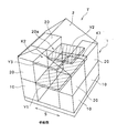
以下、本発明の好適な実施の形態について、図面を参照して説明する。図1は、本発明の実施形態に係わるユニット式建物の概略斜視図である。 DESCRIPTION OF EXEMPLARY EMBODIMENTS Hereinafter, preferred embodiments of the invention will be described with reference to the drawings. FIG. 1 is a schematic perspective view of a unit building according to an embodiment of the present invention.
図1において、ユニット式建物T(以下、ユニット住宅T)は、ユニット式住宅にパネル工法を組み合わせて構成された建物であり、建物本体1上に勾配屋根2が載置されている。この建物本体1は、略直方体状に形成され、1階に配置された建物ユニット10および2階に配置された建物ユニット20をそれぞれ複数個組み合わせて構成されている。これら複数の建物ユニット10(20)は、互いに所定の間隔Sを離して対向配置されており、建物ユニット10上に建物ユニット20が積層されている。建物ユニット10(20)は、図示しない柱の上下端をそれぞれ梁で接合した略直方体状のフレームにより構成され、柱および梁は角形鋼管やC形断面等の鋼材からなり、工場において溶接等により接合され一体に組み立てられている。隣接あるいは積層された建物ユニット10(20)同士は、連結板等を介して、ボルト締め等により互いに結合されている。
In FIG. 1, a unit type building T (hereinafter referred to as a unit house T) is a building configured by combining a unit type house with a panel method, and a
各建物ユニット10(20)を離し置いて形成された間隔Sは、構造強度や居住空間等を考慮して任意の幅として設定されている。この間隔Sは、建物ユニット10の天井高と略等しい位置に第1床パネルY1(第1の床)が架設されている。第1床パネルY1は、図1に示すように、手前側に対向配置された各建物ユニット10、10の一端から奥側に対向配置された各建物ユニット10、10の他端に架け渡されている。この第1床パネルY1は、図示しない複数の根太材に床板を貼設し、接続具により一体的に構成されている。
The spacing S formed by separating the building units 10 (20) is set as an arbitrary width in consideration of structural strength, living space, and the like. In the interval S, the first floor panel Y1 (first floor) is installed at a position substantially equal to the ceiling height of the
第1床パネルY1の上方には、第2床パネルY2(第2の床)が配置されている。第2床パネルY2は、奥側に対向配置された各建物ユニット20、20の一端から各建物ユニット20、20の他端に架け渡されている。また、軸方向においては、奥側の各建物ユニット20、20の中途部20aに架設されている。この第2床パネルY2の構造は、第1床パネルY1と同様の構造である。
A second floor panel Y2 (second floor) is disposed above the first floor panel Y1. The second floor panel Y <b> 2 is bridged from one end of each
第1床パネルY1の上方に位置し、第2床パネルY2よりも高い位置に第3床パネルY3(第3の床)が配置されている。第3床パネルY3は手前側に対向配置された各建物ユニット20、20の一端から各建物ユニット20、20の他端に架け渡されている。また、軸方向においては、手前側の各建物ユニット20、20の天井高と略等しい位置に架設されている。この第3床パネルY3の構造も第1床パネルY1および第2床パネルY2と同様の構造となっている。なお、第1床パネル10、第2床パネルY2および第3床パネルY3は、それぞれ接続具等により各床パネルを複数組み合わせて形成した床パネルユニットとしても構成することができる。この場合、予め設定された間隔Sの幅に応じて1枚のパネルユニットとして設置することができるため、施工性の向上およびコスト低減に効果的となる。
A third floor panel Y3 (third floor) is disposed above the first floor panel Y1 and at a position higher than the second floor panel Y2. The third floor panel Y3 is bridged from one end of each
上記、第1床パネルY1と第2床パネルY2とにより形成された空間は、いわゆる蔵型収納室K1(第1の大型収納室)として構成され、第3床パネルY3の上方に形成された空間は、第2の蔵型収納室K2(第2の大型収納室)として構成されている。この蔵型収納室K1および第2の蔵型収納室K2は、それぞれ天井高が約1.4mに設定された収納空間である。 The space formed by the first floor panel Y1 and the second floor panel Y2 is configured as a so-called storehouse storage room K1 (first large storage room), and is formed above the third floor panel Y3. The space is configured as a second storage chamber K2 (second large storage chamber). The storage cabinet K1 and the second storage chamber K2 are storage spaces each having a ceiling height of about 1.4 m.
すなわち、本発明では1階および2階に対向配置された各建物ユニット10、20により形成された間隔Sに、第1床パネルY1、第2床パネルY2および第3床パネルY3を上記のように架設している。そして、間隔Sに架設した第1床パネルY1と第2床パネルY2とにより、蔵型収納室K1を構成している。このため、簡易な構成とした上でも収納室用の専用ユニットが不要となるため、コストを低減することができる。また、床パネルあるいは床パネルユニットにより構成された第2床パネルY2を中途部20aに架設することで、ユニット部分およびパネル部分に設計変更が生じるのを最少減に抑えることができ、施工性を格段に向上させることとなる。勿論、第3床パネルY3を架設する際においても同様である。さらに、天井高をそれぞれ約1.4mに設定したことで、蔵型収納室K1および、第2の蔵型収納室K2は建物の延べ床面積に算入されないことになり、居住空間の有効利用を図ると共に、固定資産税等の税制度にも優遇される。
That is, in the present invention, the first floor panel Y1, the second floor panel Y2, and the third floor panel Y3 are arranged as described above in the interval S formed by the
次に、図2〜4を参照して、蔵型収納室K1および第2の蔵型収納室K2と、各階の間取りについて説明する。ユニット住宅Tの1階は、図2に示すように、西側に玄関11が配置され、その玄関11に隣接してホール12が設けられている。ホール12の北側にトイレ13および中間階へと連絡された第1階段14が配置されている。ホール12から南側には、和室15が配置されており、この和室15の南側にデッキスペース16へと連絡可能な窓15aが設けられている。ホール12の東側には、リビングダイニングキッチン17(以下、LDK17)が配置されている。LDK17は、1階の建物ユニット10の一部の柱を無くして一体的な大空間として形成されている。また、東、南および北側にそれぞれ窓17a、17b、17cが設けられた採光性に優れた空間である。窓17cは、和室15と同様にデッキスペース16へと連絡可能に配置されている。
Next, with reference to FIGS. 2 to 4, the storehouse storage room K1, the second storeroom storage room K2, and the floor plan of each floor will be described. On the first floor of the unit house T, as shown in FIG. 2, the
第1階段14を昇った中間階は、図3に示すように、廊下29の北側にトイレ21、サニタリー22およびバスルーム23がそれぞれ隣接配置され、2階の水廻りとして構成されている。第1階段14の南側には、第1居室24が配置されている。第1居室24には窓24aが設けられると共に、バルコニー26へと連絡可能な窓24b、24cがそれぞ
れ設けられている。第1居室24内に設けられた可動間仕切り25は、可動することにより居室内を自由にレイアウトして区画することができる。また、中間階の東側には、上述した蔵型収納室K1が配置されている。蔵型収納室K1は、廊下29に隣接配置された出入り口27(開口部)から出入りすることができる。この蔵型収納室K1と廊下29とは、床レベルが同一にフラットな形態として形成されている。このため、収納物を容易に収納することができる。また、蔵型収納室K1には、窓27a、27bが設けられており、換気性にも優れた構造となっている。
As shown in FIG. 3, the intermediate floor up the
蔵型収納室K1の南側に配置され、2階へと連絡する第2階段28の踊り場に隣接して、第2居室30が配置されている。図4に示すように、第2居室30は東側に窓30aが設けられている。さらに、第2階段28を昇った西側には、上述した第2の蔵型収納室K2が配置されている。この第2の蔵型収納室K2は、踊り場32に隣接して出入り口31が設けられている。これにより、収納物の収納が容易となり、利便性に優れた構造となっている。第2の蔵型収納室K2は、いわゆるロフトスペースとして構成され、第2居室30の収納物を収納することなどにより、居住空間を有効利用することができる。
The
上記、第2床パネルY2と第3床パネルY3とは図5に示すように、スキップフロアとして構成されている。したがって、大型の収納室として構成された蔵型収納室K1を設けた上でも、第2床パネルY2の上方に第2居室30を備えることができる。また、第2居室30の利便性にも配慮し、第3床パネルY3の上方に第2の蔵型収納室K2を配置している。これにより、各居室の利便性と、居住空間の有効利用を図ることができる。
The second floor panel Y2 and the third floor panel Y3 are configured as skip floors as shown in FIG. Therefore, the
なお、本実施形態では、2階建て住宅を例として述べたが、これに限定されるものではない。3階建て、あるいはそれ以上の階数とすることも可能である。しかしながら、本実施形態とすれば、2階建て住宅においても3階建てのような居住空間と、大きな収納空間を形成することができる。 In the present embodiment, a two-story house is described as an example, but the present invention is not limited to this. It is possible to have three floors or more. However, if it is set as this embodiment, also in a two-story house, a residential space like a three-story and a large storage space can be formed.
以上のように、本発明によれば、各建物ユニット10、20により形成された間隔Sに、各階を構成する第1床パネルY1、第2床パネルY2および第3床パネルY3を架設し、第1床パネルY1と第2床パネルY2とにより、蔵型収納室K1を構成し、第3床パネルY3の上方を第2の蔵型収納室K2として構成している。したがって、収納室用の専用ユニットが不要となりコストが低減される。また、ユニット部分およびパネル部分に設計変更が生じるのを最少減に抑えることができるため、施工性を格段に向上させることもできる。さらに、蔵型収納室K1および第2の蔵型収納室K2の天井高をそれぞれ約1.4mに設定したことで、建物の延べ床面積に算入されないことになり、居住空間の有効利用を図ると共に、固定資産税等の税制度にも優遇される。
As described above, according to the present invention, the first floor panel Y1, the second floor panel Y2, and the third floor panel Y3 constituting each floor are installed in the interval S formed by each
1 建物本体
2 勾配屋根
10、20 建物ユニット
11 玄関
12 ホール
13、21 トイレ
14 第1階段
15 和室
15a、17a〜17c、24a〜24c、27a、27b、30a 窓
16 デッキスペース
17 リビングダイニングキッチン
20a 中途部
22 サニタリー
23 バスルーム
24 第1居室
25 可動間仕切り
26 バルコニー
27、31 出入り口
28 第2階段
29 廊下
30 第2居室
K1 蔵型収納室
K2 第2の蔵型収納室
S 間隔
T ユニット住宅
Y1 第1床パネル
Y2 第2床パネル
Y3 第3床パネル
DESCRIPTION OF SYMBOLS 1
Claims (1)
前記積層された建物ユニットのうちの下階の建物ユニットの間隔部分に架設されて第1の床を構成する第1床パネルユニットと、前記積層された建物ユニットのうちの上階の建物ユニットの間隔部分に架設され、前記第1の床の上方に配置されて第2の床を構成する第2床パネルユニットと、同じく前記上階の建物ユニットの間隔部分に架設され、前記第2の床より高い位置に配置されて第3の床を構成する第3床パネルユニットとを備え、Of the stacked building units, a first floor panel unit that constitutes a first floor erected in a space between lower floor building units, and an upper floor building unit of the stacked building units The second floor panel unit that is installed in the space portion and is arranged above the first floor to form the second floor, and is also installed in the space portion of the building unit on the upper floor, and the second floor A third floor panel unit arranged at a higher position and constituting a third floor,
前記第1床パネルユニットは前記建物ユニット同士の所定間隔に等しい巾と前記建物ユニットの2個分の奥行きに構成されており、第2及び第3の床パネルはそれぞれ、前記建物ユニット同士の所定間隔に等しい巾と前記建物ユニットの1個分の奥行きに構成されており、The first floor panel unit is configured to have a width equal to a predetermined interval between the building units and a depth corresponding to two of the building units, and the second and third floor panels are respectively predetermined between the building units. It is composed of a width equal to the interval and a depth of one of the building units,
前記第2床パネルユニットは上階の建物ユニットの上下中途部に配置され、前記第3床パネルユニットは上階建物ユニットの天井部に配置され、更に、前記第2床パネルユニットは奥側に対向配置された建物ユニット部分に配置され、前記第3床パネルユニットは手前側建物ユニット部分に配置されることによって、前記第2の床と第3の床とがスキップフロアとして構成され、The second floor panel unit is disposed in the middle of the upper and lower building units, the third floor panel unit is disposed on the ceiling of the upper floor building unit, and the second floor panel unit is disposed on the back side. The second floor and the third floor are configured as skip floors by being arranged in the building unit part arranged opposite to each other, and the third floor panel unit is arranged in the front building unit part.
前記第1の床と第2の床とにより形成された空間を第1の大型収納室として構成し、前記第3の床の上方に形成された空間を第2の大型収納室として構成したことを特徴とするユニット式建物。The space formed by the first floor and the second floor is configured as a first large storage chamber, and the space formed above the third floor is configured as a second large storage chamber. A unit type building characterized by
Priority Applications (1)
| Application Number | Priority Date | Filing Date | Title |
|---|---|---|---|
| JP2004012698A JP4189817B2 (en) | 2004-01-21 | 2004-01-21 | Unit building |
Applications Claiming Priority (1)
| Application Number | Priority Date | Filing Date | Title |
|---|---|---|---|
| JP2004012698A JP4189817B2 (en) | 2004-01-21 | 2004-01-21 | Unit building |
Publications (2)
| Publication Number | Publication Date |
|---|---|
| JP2005207047A JP2005207047A (en) | 2005-08-04 |
| JP4189817B2 true JP4189817B2 (en) | 2008-12-03 |
Family
ID=34898998
Family Applications (1)
| Application Number | Title | Priority Date | Filing Date |
|---|---|---|---|
| JP2004012698A Expired - Fee Related JP4189817B2 (en) | 2004-01-21 | 2004-01-21 | Unit building |
Country Status (1)
| Country | Link |
|---|---|
| JP (1) | JP4189817B2 (en) |
Families Citing this family (3)
| Publication number | Priority date | Publication date | Assignee | Title |
|---|---|---|---|---|
| DE102006028752B3 (en) * | 2006-06-20 | 2008-03-06 | Bernd Nützel | Demountable building |
| JP5314398B2 (en) * | 2008-12-03 | 2013-10-16 | ミサワホーム株式会社 | Unit type building and construction method of unit type building |
| JP5371459B2 (en) * | 2009-01-22 | 2013-12-18 | ミサワホーム株式会社 | building |
-
2004
- 2004-01-21 JP JP2004012698A patent/JP4189817B2/en not_active Expired - Fee Related
Also Published As
| Publication number | Publication date |
|---|---|
| JP2005207047A (en) | 2005-08-04 |
Similar Documents
| Publication | Publication Date | Title |
|---|---|---|
| JP4189817B2 (en) | Unit building | |
| JP2021046725A (en) | Support structure and construction method of skip floor | |
| JP4092315B2 (en) | building | |
| JP2006257778A (en) | Unit type building and building unit | |
| JP6467262B2 (en) | Unit building | |
| JP5325570B2 (en) | housing complex | |
| JP5886778B2 (en) | Unit building | |
| JP2011106245A (en) | Plate-like multifamily building | |
| JP5830912B2 (en) | Apartment house and its construction method | |
| JP4246078B2 (en) | housing complex | |
| JP3840501B2 (en) | Industrialized house | |
| JP2016141978A (en) | Building | |
| JP4355244B2 (en) | building | |
| JP4597545B2 (en) | Multistory house | |
| JP5845164B2 (en) | Roof structure of unit type building | |
| JP7286375B2 (en) | building | |
| JP2009068198A (en) | Room structure with loft | |
| JP7286374B2 (en) | building | |
| JP6995480B2 (en) | Spandrel wall | |
| JP5486274B2 (en) | housing complex | |
| KR101281853B1 (en) | Method for constructing building by space utilization | |
| JP4796403B2 (en) | building | |
| JP6207176B2 (en) | Wall structure building | |
| JP2020165180A (en) | building | |
| JP2005226263A (en) | Building |
Legal Events
| Date | Code | Title | Description |
|---|---|---|---|
| A977 | Report on retrieval |
Free format text: JAPANESE INTERMEDIATE CODE: A971007 Effective date: 20061113 |
|
| A131 | Notification of reasons for refusal |
Free format text: JAPANESE INTERMEDIATE CODE: A131 Effective date: 20070213 |
|
| A521 | Request for written amendment filed |
Free format text: JAPANESE INTERMEDIATE CODE: A523 Effective date: 20070416 |
|
| A131 | Notification of reasons for refusal |
Free format text: JAPANESE INTERMEDIATE CODE: A131 Effective date: 20070717 |
|
| A521 | Request for written amendment filed |
Free format text: JAPANESE INTERMEDIATE CODE: A523 Effective date: 20070914 |
|
| A131 | Notification of reasons for refusal |
Free format text: JAPANESE INTERMEDIATE CODE: A131 Effective date: 20071225 |
|
| A711 | Notification of change in applicant |
Free format text: JAPANESE INTERMEDIATE CODE: A712 Effective date: 20080118 |
|
| RD04 | Notification of resignation of power of attorney |
Free format text: JAPANESE INTERMEDIATE CODE: A7424 Effective date: 20080206 |
|
| A521 | Request for written amendment filed |
Free format text: JAPANESE INTERMEDIATE CODE: A523 Effective date: 20080225 |
|
| A02 | Decision of refusal |
Free format text: JAPANESE INTERMEDIATE CODE: A02 Effective date: 20080527 |
|
| RD02 | Notification of acceptance of power of attorney |
Free format text: JAPANESE INTERMEDIATE CODE: A7422 Effective date: 20080625 |
|
| A521 | Request for written amendment filed |
Free format text: JAPANESE INTERMEDIATE CODE: A523 Effective date: 20080711 |
|
| A911 | Transfer to examiner for re-examination before appeal (zenchi) |
Free format text: JAPANESE INTERMEDIATE CODE: A911 Effective date: 20080731 |
|
| TRDD | Decision of grant or rejection written | ||
| A01 | Written decision to grant a patent or to grant a registration (utility model) |
Free format text: JAPANESE INTERMEDIATE CODE: A01 Effective date: 20080819 |
|
| A01 | Written decision to grant a patent or to grant a registration (utility model) |
Free format text: JAPANESE INTERMEDIATE CODE: A01 |
|
| A61 | First payment of annual fees (during grant procedure) |
Free format text: JAPANESE INTERMEDIATE CODE: A61 Effective date: 20080904 |
|
| FPAY | Renewal fee payment (event date is renewal date of database) |
Free format text: PAYMENT UNTIL: 20110926 Year of fee payment: 3 |
|
| R150 | Certificate of patent or registration of utility model |
Ref document number: 4189817 Country of ref document: JP Free format text: JAPANESE INTERMEDIATE CODE: R150 Free format text: JAPANESE INTERMEDIATE CODE: R150 |
|
| FPAY | Renewal fee payment (event date is renewal date of database) |
Free format text: PAYMENT UNTIL: 20110926 Year of fee payment: 3 |
|
| FPAY | Renewal fee payment (event date is renewal date of database) |
Free format text: PAYMENT UNTIL: 20120926 Year of fee payment: 4 |
|
| FPAY | Renewal fee payment (event date is renewal date of database) |
Free format text: PAYMENT UNTIL: 20120926 Year of fee payment: 4 |
|
| FPAY | Renewal fee payment (event date is renewal date of database) |
Free format text: PAYMENT UNTIL: 20130926 Year of fee payment: 5 |
|
| LAPS | Cancellation because of no payment of annual fees |