JP4184566B2 - connector - Google Patents
connector Download PDFInfo
- Publication number
- JP4184566B2 JP4184566B2 JP2000039055A JP2000039055A JP4184566B2 JP 4184566 B2 JP4184566 B2 JP 4184566B2 JP 2000039055 A JP2000039055 A JP 2000039055A JP 2000039055 A JP2000039055 A JP 2000039055A JP 4184566 B2 JP4184566 B2 JP 4184566B2
- Authority
- JP
- Japan
- Prior art keywords
- rib
- connector housing
- male
- female
- fitted
- Prior art date
- Legal status (The legal status is an assumption and is not a legal conclusion. Google has not performed a legal analysis and makes no representation as to the accuracy of the status listed.)
- Expired - Fee Related
Links
- 238000003780 insertion Methods 0.000 claims description 6
- 230000037431 insertion Effects 0.000 claims description 6
- 239000002184 metal Substances 0.000 claims description 6
- 230000013011 mating Effects 0.000 description 6
- 230000000694 effects Effects 0.000 description 3
- 210000000078 claw Anatomy 0.000 description 2
- 238000004519 manufacturing process Methods 0.000 description 2
- 229920003002 synthetic resin Polymers 0.000 description 2
- 239000000057 synthetic resin Substances 0.000 description 2
- 230000003796 beauty Effects 0.000 description 1
- 230000015572 biosynthetic process Effects 0.000 description 1
- 238000012986 modification Methods 0.000 description 1
- 230000004048 modification Effects 0.000 description 1
Images


Landscapes
- Details Of Connecting Devices For Male And Female Coupling (AREA)
Description
【0001】
【発明の属する技術分野】
本発明は、一方のコネクタハウジングに対して他方のコネクタハウジングをこじることなく嵌合できるコネクタに関する。
【0002】
【従来の技術】
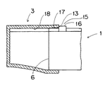
図6において、コネクタ装置は合成樹脂製の雄コネクタハウジング1と、雄コネクタハウジング1を嵌合して収容するための嵌合穴2を有する合成樹脂製の雌コネクタハウジング3とからなる。雄コネクタハウジング1の後面4からは、雌型の金属端子5(以下「雄型端子」という)が所定の挿入孔に挿入されている。8はその前端面6に設けた相手側の金属端子を挿入するための挿入孔である。この相手側の金属端子は雌コネクタハウジング3の後面7に設けた所定の挿入孔に挿入して固定されている。相手側金属端子の先端部は、雄状の雄型端子であり、嵌合穴2に突出して臨んでいる。これにより、雄コネクタハウジング1を雌コネクタハウジング3に嵌合するとき、挿入孔8が雄型端子を収容せしめ、電気接続を達成する。
また、雄コネクタハウジング1の後面と前端面6との間に存する上側面に、雌雄両コネクタハウジング3,1を嵌合する方向に延びる第一のリブ9と副リブ10が設けられる。他方、雄コネクタハウジング3には、第一のリブ9を案内する第一のリブ溝11と、副リブ10を案内するための副リブ溝12とが設けられている。
これらの第一のリブ9,9は、雄コネクタハウジング1を雌コネクタハウジング3に対して円滑に嵌合させるためのものである。従って、嵌合する方向とは斜交する方向、すなわち、雄コネクタハウジング1を雌コネクタハウジング3に対して無理に押し込むことにより、両ハウジング1,3が互いにこじれて嵌合するのを防ぐように、すなわち、こじり方向に嵌合するのを防止するために形成されたものである。
コネクタを組み立てるのには、次のようにして行われていた。先ず、雄コネクタハウジング1に予め雌型端子5が挿入されて一体化される。同様に雌コネクタハウジング3にも雄型端子が挿入されて一体化される。一点鎖線で示すように、雄コネクタハウジング1はその前端面6を雌コネクタハウジング3の前面開口部の前端面13から嵌合穴2に進入させる。このとき各リブ9と、副リブ10に案内されて雌雄両コネクタハウジング1,3は合体してコネクタが得られる。
【0003】
【発明が解決しようとする課題】
ところが、従来装置にあっては、図7,8に示すように、こじり方向の嵌合を阻止するための第一のリブ9,9を形成しているにもかかわらず、雄コネクタハウジング1を嵌合する方向に対して斜交する方向で雌コネクタハウジング3に押し込む場合があった。このとき、第一のリブ9,9は第一のリブ溝11,11以外の嵌合穴2の内面に嵌込まれる状態となるが、さらに無理に押し込んで嵌合させようとすると、雌コネクタハウジング3の下側面等を広げるように変形させながら雄コネクタハウジング1が嵌合穴2に進入する。その結果、嵌合穴2に臨んでる雄型端子をこじり、折損や変形を生じさせ正しい嵌合方向に嵌合させようとしても、もはや雄型端子が損傷しているために嵌合できず、雌コネクタハウジング3等を全部新たに取り替えなければならないこともあり、ひいてはコネクタ装置の組み立て作業の効率低下、製造コストが高くなるという恐れがあった。
【0004】
本発明は、上述した事情に鑑みて工夫されたもので、一方のコネクタハウジングを他方のコネクタハウジングに対して、こじり方向に無理矢理に押し込むことを阻止して、他方のコネクタハウジングの嵌合穴にある雄型端子の折損等を未然に回避しうるこじり阻止機構を具えたコネクタを得ることを目的とする。
【0005】
【課題を解決するための手段】
前記課題を解決するためなされた請求項1記載の発明に係るコネクタは、相互に嵌合する雄雌の金属端子のうちの雌型端子を挿入、固定されている雄コネクタハウジングと、前記雌型端子が嵌合される雄型端子が挿入、固定されている雌コネクタハウジングと、が設けられ、かつ、前記雄コネクタハウジングの上側面両端縁に沿って、一対の第一のリブと、前記雌コネクタハウジングに前記第一のリブを案内する第一のリブ溝と、が設けられたコネクタにおいて、
前記雄コネクタハウジングの前記第一のリブ間に、前記雌コネクタハウジングに挿入、固定されている前記雄型端子が折損や変形を生じさせないように、前記雄コネクタハウジングの前端面から奥まった位置に前記第一のリブよりも高さの高い第二のリブが設けられ、
前記第一のリブ溝よりも深い溝を有する、前記第二のリブを案内する、第二のリブ溝が、前記雌コネクタハウジングに形成され、そして、
前記雄コネクタハウジングが、前記雌コネクタハウジングにこじり方向に嵌合されるとき、前記第二のリブが、前記雌コネクタハウジングの前端面に当接されて前記こじり方向への前記雄コネクタハウジングの嵌合が阻止されるように構成されている、
ことを特徴とする。
【0006】
請求項2記載の発明に係るコネクタは、請求項1記載のコネクタに係り、前記雄コネクタハウジングの前端面まで連続して延びる、前記第二のリブの高さよりも低い、補助リブが前記第二のリブに設けられていることを特徴とする。
【0007】
請求項3記載の発明に係るコネクタは、請求項1記載のコネクタに係り、前記補助リブが、前記第一のリブとほぼ同じ高さに形成されていることを特徴とする。
【0008】
請求項1記載の発明によれば、雄コネクタハウジングの上側面であってその前端面から奥まった位置に、第一のリブよりも高さの高い第二のリブが設けられ、雌コネクタハウジングには第一のリブ溝よりも深さの深い第二のリブ溝を形成したため、雄のコネクタハウジングを雌のコネクタハウジングに対してこじる方向に嵌合しようとするとき、第二のリブが雌のコネクタハウジングの前端面に突き当たり、こじり嵌合をしていることがわかる。
【0009】
請求項2記載の発明によれば、第二のリブよりも高さの低い補助リブが、第二のリブにコネクタハウジングの前端面まで連続するように延ばして形成されたため、両コネクタハウジングを嵌合させるとき、その嵌合当初においては補助リブが第二のリブ溝に案内されるので、円滑な嵌合作業を行える。
【0010】
請求項3記載の発明によれば、第二のリブに連続して設けられた補助リブが、雌のコネクタハウジングに設けられた第一のリブとほぼ同じ高さに形成されているため、第二のリブ溝に円滑に案内され、良好な嵌合姿勢に持っていくことができ、こじる方向への嵌合を阻止する。
【0011】
【発明の実施の形態】
以下、本発明の実施の形態を図1に基づいて説明する。
図1は本実施の形態であるコネクタの組み立て分解を示した外観斜視図である。上記従来装置と実質的に同一部分、部材または均等部材には、上記従来装置に用いたと同一符号を付してその説明を省略することとし、相違する構成のみを説明する。
【0012】
すなわち、雄コネクタハウジング1の上側面14に形成された第一のリブ9および副リブ10間に、嵌合する方向に延びる一対のリブ手段15が突設される。該リブ手段15は、第二のリブ16と、該第二のリブ16から前端面6に連続して延びると共に第二のリブ16より高さの低い補助リブ17とからなる。この第二のリブ16は第一のリブ9や副リブ10よりも上側面14からの高さが高くなるように形成される。一方、前端面6からLだけ奥まった位置には、第二のリブ16と段差をなして連続する補助リブ17が設けられていて、第二のリブ16との間で段差部151が形成される。補助リブ17は第一のリブ9や副リブ10とほぼ同じ高さを有する。
雌コネクタハウジング3には第二のリブ16を案内すると共に第一のリブ溝11よりも深い第二のリブ溝18が凹設される。
【0013】
補助リブ17は、雄コネクタハウジング1を雌コネクタハウジング3に嵌合する当初において、嵌合しやすくするためのものであり、第二のリブ16は、両ハウジング1,3がこじり方向に嵌合しようとするとき、第二のリブ16が雌コネクタハウジング3の開口部の前端面13に当接することで、それ以上はこじり方向への嵌合ができないようにするためのもにである。
なお、符号19は被係止部20に係止する係止爪であり、嵌合時に係止爪19が被係止部20に係合することで、雌雄両コネクタハウジング3,1の結合がガタつかないようにするものである。
【0014】
本実施の形態の作用を説明する。雄コネクタハウジング1が雌コネクタハウジング3に対して、正常に嵌合されるとき、リブ手段15の補助リブ17は第二のリブ溝18に、また第一のリブ9,副リブ10はそれぞれ第一のリブ溝11,副溝12に嵌まる。さらに押し込むことで第二のリブ16も第二のリブ溝18に入る。従って、雌雄両コネクタハウジング3,1は雄型端子を何ら損傷させることなく嵌合されてコネクタを完成させることができる。
【0015】
他方、図2〜4のように誤って雄コネクタハウジング1を雌コネクタハウジング3に対して、こじり方向に嵌合させようとするとき、雄コネクタハウジング1の第一のリブ9は第一のリブ溝11に嵌まらないで、嵌合穴2の天井に圧入して、雌コネクタハウジング3を外側に拡大するように変形させる。
ところが、このとき第二のリブ16が拡大変形した雌コネクタハウジング3の開口部前端面13に当接する。これにより、それ以上雄コネクタハウジング1を雌コネクタハウジング3へ押し込むことができなくなり、雌コネクタハウジング3内の雄型端子の損傷を確実に阻止することができる。
この場合には、一旦雄コネクタハウジング1を雌コネクタハウジング3から抜いて分離し、改めて雌コネクタハウジング3に嵌合を行うことができる。
従って、雌雄のコネクタハウジング3,1の嵌合組み立て作業の効率を向上でき、製造コストの安価なコネクタ装置を得ることができるといった効果を奏する。
【0016】
以上、本実施の形態を具体的に詳述してきたが、具体的な構成はこの形態に限られるものではなく、本発明の要旨を逸脱しない範囲の設計変更等があっても本発明に含まれる。
例えば、上記実施の形態では、こじりを阻止するリブ手段15に段差部151を有する形状にしたが、これを図5に示すように段差部151すなわち段差を有しない形状にしてもよい。すなわち補助リブ17のない上記第二のリブ16に相当する高さを有する第二のリブ16だけに形成してもよいものである。
また、こじり阻止用のリブ手段15を雄コネクタハウジング1に設け、これに係合する第二のリブ溝18を雌コネクタハウジング3に設けたが、逆にリブ手段15を雌コネクタハウジング3に設け、第二のリブ溝18を雄コネクタハウジング1側に設けることもできる。
【0017】
【発明の効果】
以上説明したように、請求項1に記載された本発明によれば、こじり方向の嵌合により雄コネクタハウジングがこじりによる雌コネクタハウジングの変形により若干嵌入したとしても、二次的に第二のリブが雌コネクタハウジングの前端面に当接することにより、それ以上嵌入させることができなくなり、確実にこじりを防止できる効果を奏する。
請求項2に記載の本発明によれば、第二のリブよりも低い補助リブが雄コネクタハウジングの前端面から第一のリブまで連続して設けたため、嵌合当初は補助リブも第二のリブ溝にガイドされ、嵌合を円滑に行える効果を奏する。
請求項3に記載の本発明によれば、補助リブは第一のリブとほぼ同じ高さに形成したため、補助リブを第二のリブ溝に円滑に案内され、良好な嵌合姿勢に持っていくことができ、こじり方向への嵌合を阻止する。
【図面の簡単な説明】
【図1】本発明による一実施の形態に係るコネクタに係り、雄コネクタハウジングと雌コネクタハウジングとの組み立て分解を示す外観斜視図である。
【図2】図1の雄コネクタハウジングが雌コネクタハウジングにこじり方向に嵌合している状態を概念的に示す概略平面図である。
【図3】図2を矢印A方向から見た状態を概念的に示した側面図である。
【図4】図2のB−B線における矢視部分拡大断面図である。
【図5】一実施の形態の変形例における外観斜視図である。
【図6】従来装置におけるコネクタの組み立て分解を示す外観斜視図である。
【図7】雄コネクタハウジングが雌コネクタハウジングに対してこじり方向に嵌合する状態を概念的に示す平面図である。
【図8】図7の矢印C方向から視た概念的な側面図である。
【符号の説明】
1 雄コネクタハウジング
2 嵌合穴
3 雌コネクタハウジング
4 後面
5 雌型端子
6 前端面
13 前端面
15 リブ手段
16,20 第二のリブ
17 補助リブ
18 第二のリブ溝[0001]
BACKGROUND OF THE INVENTION
The present invention relates to a connector that can be fitted to one connector housing without squeezing the other connector housing.
[0002]
[Prior art]
In FIG. 6, the connector device includes a
Further, a
These
To Ru assembly of the connector it has been carried out in the following manner. First, the female terminal 5 is inserted into the male connector housing 1 in advance and integrated. Similarly, male terminals are inserted into the
[0003]
[Problems to be solved by the invention]
However, in the conventional apparatus, as shown in FIGS. 7 and 8, the
[0004]
The present invention has been devised in view of the above-described circumstances, and forcibly pushing one connector housing into the other connector housing in the twisting direction to the fitting hole of the other connector housing. It is an object of the present invention to provide a connector having a kink preventing mechanism that can avoid breakage of a male terminal.
[0005]
[Means for Solving the Problems]
In order to solve the above-mentioned problem, a connector according to the invention of
Between the first rib of the male connector housing, the insertion into the female connector housing, so that the male terminal is fixed does not cause breakage or deformation, a position recessed from the front end surface of the male connector housing the taller than the first rib second rib is provided,
Having the first deep grooves than the rib grooves, for guiding the second rib, the second rib grooves is formed in the female connector housing, and,
The male connector housing, wherein when fitted to the direction twisting the female connector housing, said second ribs, fitted in the male connector housing to the female connector abutted said prying direction to the front end surface of the housing if is configured so that is prevented,
It is characterized by that.
[0006]
Connector according to the second aspect of the invention relates to a connector according to
[0007]
A connector according to a third aspect of the invention relates to the connector according to the first aspect, wherein the auxiliary rib is formed at substantially the same height as the first rib.
[0008]
According to the first aspect of the invention, in its front end face or we recessed position a side on the male connector housing, the second rib higher height than the first rib is provided, the female connector housing Has a second rib groove deeper than the first rib groove, so that when the male connector housing is to be fitted to the female connector housing in a direction to bend, the second rib is female. It can be seen that the connector housing abuts against the front end face of the connector housing and is engaged with the connector housing.
[0009]
According to the second aspect of the present invention, since the lower auxiliary rib height than the second rib, which is formed to extend so as to be continuous to the front end face of the connector housing to a second rib, fitting the two connector housings When mating, since the auxiliary rib is guided to the second rib groove at the beginning of the mating, a smooth mating operation can be performed.
[0010]
According to the third aspect of the present invention, since the auxiliary rib provided continuously to the second rib is formed at substantially the same height as the first rib provided on the female connector housing, the It is smoothly guided by the second rib groove, can be brought into a good fitting posture, and is prevented from fitting in a twisting direction.
[0011]
DETAILED DESCRIPTION OF THE INVENTION
Hereinafter, an embodiment of the present invention will be described with reference to FIG.
FIG. 1 is an external perspective view showing assembly and disassembly of the connector according to the present embodiment. The substantially same parts, members, or equivalent members as those of the conventional apparatus will be denoted by the same reference numerals as those used in the conventional apparatus, and the description thereof will be omitted, and only different configurations will be described.
[0012]
That is, between the
The
[0013]
The
[0014]
The operation of the present embodiment will be described. When the
[0015]
On the other hand, when the
However, at this time, the
In this case, the
Therefore, it is possible to improve the efficiency of the assembling work of the male and
[0016]
As described above, the present embodiment has been specifically described in detail. However, the specific configuration is not limited to this embodiment, and design changes and the like within the scope of the present invention are included in the present invention. It is.
For example, in the above embodiment, the rib means 15 for preventing the twisting has the shape having the stepped portion 151. However, as shown in FIG. 5, the stepped portion 151, that is, the shape having no stepped portion may be used. That is, it may be formed only on the
Further, the rib means 15 for preventing twisting is provided in the
[0017]
【The invention's effect】
As described above, according to the present invention described in
According to the present invention described in
According to the third aspect of the present invention, since the auxiliary rib is formed at substantially the same height as the first rib, the auxiliary rib is smoothly guided to the second rib groove and has a good fitting posture. And prevents fitting in the twisting direction.
[Brief description of the drawings]
FIG. 1 is an external perspective view showing assembly / disassembly of a male connector housing and a female connector housing according to a connector according to an embodiment of the present invention.
FIG. 2 is a schematic plan view conceptually showing a state in which the male connector housing of FIG. 1 is fitted to the female connector housing in a twisting direction.
FIG. 3 is a side view conceptually showing the state of FIG. 2 viewed from the direction of arrow A.
4 is a partial enlarged cross-sectional view taken along the line BB in FIG. 2;
FIG. 5 is an external perspective view of a modification of the embodiment.
FIG. 6 is an external perspective view showing assembly / disassembly of a connector in a conventional apparatus.
FIG. 7 is a plan view conceptually showing a state in which the male connector housing is fitted to the female connector housing in a twisting direction.
8 is a conceptual side view seen from the direction of arrow C in FIG.
[Explanation of symbols]
1
Claims (3)
前記雄コネクタハウジングの前記第一のリブ間に、前記雌コネクタハウジングに挿入、固定されている前記雄型端子が折損や変形を生じさせないように、前記雄コネクタハウジングの前端面から奥まった位置に前記第一のリブよりも高さの高い第二のリブが設けられ、
前記第一のリブ溝よりも深い溝を有する、前記第二のリブを案内する、第二のリブ溝が、前記雌コネクタハウジングに形成され、そして
前記雄コネクタハウジングが、前記雌コネクタハウジングにこじり方向に嵌合されるとき、前記第二のリブが、前記雌コネクタハウジングの前端面に当接されて前記こじり方向への前記雄コネクタハウジングの嵌合が阻止されるように構成されている、
ことを特徴とするコネクタ。 A male connector housing in which a female terminal of male and female metal terminals to be fitted to each other is inserted and fixed, and a female connector housing in which a male terminal to which the female terminal is fitted is inserted and fixed. When, it is provided, and, along the side opposite edges on said male connector housing, a pair of first ribs, the first rib grooves for guiding the first rib on the female connector housing, but In the provided connector,
Between the first rib of the male connector housing, the insertion into the female connector housing, so that the male terminal is fixed does not cause breakage or deformation, a position recessed from the front end surface of the male connector housing the taller than the first rib second rib is provided,
Having the deep grooves than the first rib grooves, for guiding the second rib, the second rib grooves is formed in the female connector housing and said male connector housing, prying the female connector housing when fitted to the direction, the second ribs, the fitting of the male connector housing to the female connector front surface contact has been the prying direction of the housing is configured so that is prevented,
A connector characterized by that.
Priority Applications (1)
| Application Number | Priority Date | Filing Date | Title |
|---|---|---|---|
| JP2000039055A JP4184566B2 (en) | 2000-02-17 | 2000-02-17 | connector |
Applications Claiming Priority (1)
| Application Number | Priority Date | Filing Date | Title |
|---|---|---|---|
| JP2000039055A JP4184566B2 (en) | 2000-02-17 | 2000-02-17 | connector |
Publications (2)
| Publication Number | Publication Date |
|---|---|
| JP2001230021A JP2001230021A (en) | 2001-08-24 |
| JP4184566B2 true JP4184566B2 (en) | 2008-11-19 |
Family
ID=18562680
Family Applications (1)
| Application Number | Title | Priority Date | Filing Date |
|---|---|---|---|
| JP2000039055A Expired - Fee Related JP4184566B2 (en) | 2000-02-17 | 2000-02-17 | connector |
Country Status (1)
| Country | Link |
|---|---|
| JP (1) | JP4184566B2 (en) |
Families Citing this family (31)
| Publication number | Priority date | Publication date | Assignee | Title |
|---|---|---|---|---|
| JP4052642B2 (en) | 2003-02-27 | 2008-02-27 | 住友電装株式会社 | connector |
| US7627343B2 (en) | 2003-04-25 | 2009-12-01 | Apple Inc. | Media player system |
| US6776660B1 (en) | 2003-04-30 | 2004-08-17 | Japan Aviation Electronics Industry, Limited | Connector |
| US7441058B1 (en) | 2006-09-11 | 2008-10-21 | Apple Inc. | Method and system for controlling an accessory having a tuner |
| US7673083B2 (en) | 2004-04-27 | 2010-03-02 | Apple Inc. | Method and system for controlling video selection and playback in a portable media player |
| US7293122B1 (en) | 2004-04-27 | 2007-11-06 | Apple Inc. | Connector interface system facilitating communication between a media player and accessories |
| US7529872B1 (en) | 2004-04-27 | 2009-05-05 | Apple Inc. | Communication between an accessory and a media player using a protocol with multiple lingoes |
| US7634605B2 (en) | 2004-04-27 | 2009-12-15 | Apple Inc. | Method and system for transferring stored data between a media player and an accessory |
| US7441062B2 (en) | 2004-04-27 | 2008-10-21 | Apple Inc. | Connector interface system for enabling data communication with a multi-communication device |
| US7529871B1 (en) | 2004-04-27 | 2009-05-05 | Apple Inc. | Communication between an accessory and a media player with multiple protocol versions |
| US7826318B2 (en) | 2004-04-27 | 2010-11-02 | Apple Inc. | Method and system for allowing a media player to transfer digital audio to an accessory |
| US7895378B2 (en) | 2004-04-27 | 2011-02-22 | Apple Inc. | Method and system for allowing a media player to transfer digital audio to an accessory |
| US8117651B2 (en) | 2004-04-27 | 2012-02-14 | Apple Inc. | Method and system for authenticating an accessory |
| US7529870B1 (en) | 2004-04-27 | 2009-05-05 | Apple Inc. | Communication between an accessory and a media player with multiple lingoes |
| US7526588B1 (en) | 2004-04-27 | 2009-04-28 | Apple Inc. | Communication between an accessory and a media player using a protocol with multiple lingoes |
| US7797471B2 (en) | 2004-04-27 | 2010-09-14 | Apple Inc. | Method and system for transferring album artwork between a media player and an accessory |
| US7823214B2 (en) | 2005-01-07 | 2010-10-26 | Apple Inc. | Accessory authentication for electronic devices |
| US7525216B2 (en) | 2005-01-07 | 2009-04-28 | Apple Inc. | Portable power source to provide power to an electronic device via an interface |
| US7632114B2 (en) | 2006-03-30 | 2009-12-15 | Apple Inc. | Interface connecter between media player and other electronic devices |
| US8006019B2 (en) | 2006-05-22 | 2011-08-23 | Apple, Inc. | Method and system for transferring stored data between a media player and an accessory |
| US7415563B1 (en) | 2006-06-27 | 2008-08-19 | Apple Inc. | Method and system for allowing a media player to determine if it supports the capabilities of an accessory |
| US7558894B1 (en) | 2006-09-11 | 2009-07-07 | Apple Inc. | Method and system for controlling power provided to an accessory |
| US7540788B2 (en) | 2007-01-05 | 2009-06-02 | Apple Inc. | Backward compatible connector system |
| US8095713B2 (en) | 2007-09-04 | 2012-01-10 | Apple Inc. | Smart cables |
| JP5050823B2 (en) * | 2007-12-10 | 2012-10-17 | 住友電装株式会社 | connector |
| US8208853B2 (en) | 2008-09-08 | 2012-06-26 | Apple Inc. | Accessory device authentication |
| US8238811B2 (en) | 2008-09-08 | 2012-08-07 | Apple Inc. | Cross-transport authentication |
| JP6279257B2 (en) | 2013-08-30 | 2018-02-14 | 矢崎総業株式会社 | Connection structure between electronic parts and terminal fittings |
| JP5737446B1 (en) * | 2014-03-07 | 2015-06-17 | 第一精工株式会社 | Electrical connector mating structure |
| CN111262080A (en) * | 2020-03-19 | 2020-06-09 | 昆山维康电子有限公司 | PC board end anti-loosening and interference-free female connector |
| JP2024025906A (en) * | 2022-08-15 | 2024-02-28 | 住友電装株式会社 | connector assembly |
-
2000
- 2000-02-17 JP JP2000039055A patent/JP4184566B2/en not_active Expired - Fee Related
Also Published As
| Publication number | Publication date |
|---|---|
| JP2001230021A (en) | 2001-08-24 |
Similar Documents
| Publication | Publication Date | Title |
|---|---|---|
| JP4184566B2 (en) | connector | |
| US5613881A (en) | Connector | |
| US6059612A (en) | Block connector | |
| JP4082176B2 (en) | connector | |
| JP3301329B2 (en) | connector | |
| JPH06231824A (en) | Prying fit preventing structure for connector | |
| JP2001332342A (en) | Lever connector | |
| JP2001345149A (en) | Inertial lock connector | |
| US6022238A (en) | Double lock for connector | |
| JPH10112355A (en) | Rattling prevention structure for electrical connectors | |
| JP2001237026A (en) | Connector with lever | |
| JPH09245869A (en) | Connector with terminal lock | |
| JP3753019B2 (en) | connector | |
| JP3415946B2 (en) | Electrical connector | |
| US20040171294A1 (en) | Connector | |
| JP2006147474A (en) | Waterproof connector | |
| JP4492433B2 (en) | connector | |
| JP3341820B2 (en) | Coupling type connector | |
| JP3687537B2 (en) | Split connector | |
| JP3864801B2 (en) | connector | |
| JP4081916B2 (en) | connector | |
| JP5067204B2 (en) | Connector locking mechanism and locking method | |
| JP3770050B2 (en) | Lever type connector | |
| JPH11176517A (en) | Combined connector and joined structure of combined connector and casing | |
| JP2005222758A (en) | Connector |
Legal Events
| Date | Code | Title | Description |
|---|---|---|---|
| A977 | Report on retrieval |
Free format text: JAPANESE INTERMEDIATE CODE: A971007 Effective date: 20050810 |
|
| A131 | Notification of reasons for refusal |
Free format text: JAPANESE INTERMEDIATE CODE: A131 Effective date: 20050816 |
|
| A521 | Written amendment |
Free format text: JAPANESE INTERMEDIATE CODE: A523 Effective date: 20051014 |
|
| A02 | Decision of refusal |
Free format text: JAPANESE INTERMEDIATE CODE: A02 Effective date: 20060322 |
|
| A521 | Written amendment |
Free format text: JAPANESE INTERMEDIATE CODE: A523 Effective date: 20060512 |
|
| A911 | Transfer of reconsideration by examiner before appeal (zenchi) |
Free format text: JAPANESE INTERMEDIATE CODE: A911 Effective date: 20060524 |
|
| A912 | Removal of reconsideration by examiner before appeal (zenchi) |
Free format text: JAPANESE INTERMEDIATE CODE: A912 Effective date: 20060623 |
|
| A521 | Written amendment |
Free format text: JAPANESE INTERMEDIATE CODE: A523 Effective date: 20080717 |
|
| A01 | Written decision to grant a patent or to grant a registration (utility model) |
Free format text: JAPANESE INTERMEDIATE CODE: A01 |
|
| A61 | First payment of annual fees (during grant procedure) |
Free format text: JAPANESE INTERMEDIATE CODE: A61 Effective date: 20080904 |
|
| FPAY | Renewal fee payment (event date is renewal date of database) |
Free format text: PAYMENT UNTIL: 20110912 Year of fee payment: 3 |
|
| R150 | Certificate of patent or registration of utility model |
Free format text: JAPANESE INTERMEDIATE CODE: R150 |
|
| A521 | Written amendment |
Free format text: JAPANESE INTERMEDIATE CODE: A523 Effective date: 20060512 |
|
| LAPS | Cancellation because of no payment of annual fees |