JP4147054B2 - Stereoscopic observation device - Google Patents
Stereoscopic observation device Download PDFInfo
- Publication number
- JP4147054B2 JP4147054B2 JP2002142544A JP2002142544A JP4147054B2 JP 4147054 B2 JP4147054 B2 JP 4147054B2 JP 2002142544 A JP2002142544 A JP 2002142544A JP 2002142544 A JP2002142544 A JP 2002142544A JP 4147054 B2 JP4147054 B2 JP 4147054B2
- Authority
- JP
- Japan
- Prior art keywords
- image
- observation apparatus
- image display
- stereoscopic observation
- observer
- Prior art date
- Legal status (The legal status is an assumption and is not a legal conclusion. Google has not performed a legal analysis and makes no representation as to the accuracy of the status listed.)
- Expired - Fee Related
Links
Images


Classifications
-
- G—PHYSICS
- G02—OPTICS
- G02B—OPTICAL ELEMENTS, SYSTEMS OR APPARATUS
- G02B30/00—Optical systems or apparatus for producing three-dimensional [3D] effects, e.g. stereoscopic images
- G02B30/20—Optical systems or apparatus for producing three-dimensional [3D] effects, e.g. stereoscopic images by providing first and second parallax images to an observer's left and right eyes
- G02B30/26—Optical systems or apparatus for producing three-dimensional [3D] effects, e.g. stereoscopic images by providing first and second parallax images to an observer's left and right eyes of the autostereoscopic type
Landscapes
- Physics & Mathematics (AREA)
- General Physics & Mathematics (AREA)
- Optics & Photonics (AREA)
- Testing, Inspecting, Measuring Of Stereoscopic Televisions And Televisions (AREA)
- Stereoscopic And Panoramic Photography (AREA)
- Lenses (AREA)
Description
【0001】
【発明の属する技術分野】
本発明は、観察者が立体視用の眼鏡を用いることなしに立体視し得る立体観察装置に関する。
【0002】
【従来の技術】
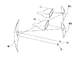
図15に示されたように、従来、1枚の対眼凹面鏡MEと、これに対向する2枚の対画凹面鏡MPR,MPLと、この対画凹面鏡の各々に対向する2個の画像提示装置PR,PLとを特定の配置関係に構成してなる立体映像観視装置が、知られている(特開昭51−24116号公報参照)。
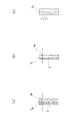
即ち、この公知の立体映像観視装置では、説明の便宜上、図15の装置を上下を逆にして側方から見た図16に示すように、左右両眼のそれぞれの視位置(瞳位置)ER(EL)と、左右両眼の対眼凹面鏡MEによる夫々の像ER'(EL')の位置と、この像の対画凹面鏡MPR(MPL)による夫々の像ER"(EL")の位置と、対眼凹面鏡の曲率中心CER(CEL)及び対画凹面鏡の夫々の曲率中心CPR(CPL)とが夫々一線上になるように配置されていている。
【0003】
【発明が解決しようとする課題】
ところで、この公知の装置では、凹面鏡の面精度や取付け誤差による像の歪みや焦点位置の変動が大きいため、凹面鏡の製作コストや取付けコストが高価なものになるという問題点がある。
また、観察者の視位置が特定の位置から外れると、画像が大きく歪むため、観察位置及び観察姿勢が限定されてしまい、観察時の取扱いが不便であるうという問題点がある。
また、観察の自由度を上げるためには、射出瞳を大きくする必要があるが、この装置において射出瞳を大きくするためには、凹面鏡を大きくしなければならず、装置全体が大型化するという問題点がある。
【0004】
本発明は、従来装置の有するこのような問題点に鑑みてなされたものであり、その目的とするところは、観察者の視位置が動いても常に歪みのない良好な画像を見ることができるコンパクトな構成の立体観察装置を提供することにある。
【0005】
【課題を解決するための手段】
上記の目的を達成するため、本発明による立体視観察装置は、右眼用画像と左眼用画像を投影する一対の画像投影手段と、該一対の画像投影手段の各開口を観察者の左右眼の瞳位置に結像させる結像手段を備えた一つの画像表示手段とを有する立体観察装置において、観察者の瞳の動きを検出する検出手段と、観察者の瞳の動きに伴う前記検出手段からの出力の変化に基づき前記画像表示手段を観察者の瞳の動きに追従して動かす駆動手段とを有し、前記画像表示手段は拡散手段を前記結像手段と隣接する位置に備え、前記結像手段はフレネル面を備え前記画像表示手段の中心に対して偏芯している光学部材であることを特徴としている。
【0006】
本発明によれば、前記一対の画像投影手段と前記画像表示手段と前記検出手段と前記駆動手段は一つの支持体に装着されていて、前記検出手段は、観察者の左右眼の瞳又は顔を照射する赤外光を出射する赤外LEDと、前記瞳の網膜反射像又は観察者の顔の輪郭を撮影する赤外カメラとを含んでいる。
【0007】
また、本発明によれば、前記一対の画像投影手段と前記画像表示手段と前記検出手段と前記駆動手段は一つの支持体に装着されていて、前記検出手段は、観察者の顔を照射する可視光を射出するLEDと、前記観察者の顔の輪郭を撮影するカメラとを含んでいる。
【0008】
また、本発明によれば、前記一対の画像投影手段と前記画像表示手段と前記検出手段と前記駆動手段は一つの支持体に装着されていて、前記検出手段は、観察者の顔を照射する赤外光又は可視光を射出するLEDと、該LEDにより照射された顔の輪郭を捕捉するエッジ検出画像の出力が可能なCMOSイメージセンサとを含んでいる。
【0009】
また、本発明によれば、前記一対の画像投影手段と前記画像表示手段と前記検出手段は一つの第1の支持体に装着されていて、該第1の支持体は前記駆動手段を介して第2の支持体に装着されており、前記駆動手段は、前記第1の支持体を介して、前記一対の画像投影手段と前記画像表示手段と前記検出手段を前記第2の支持体に対して一体的に動かすようになっている。
【0010】
また、本発明によれば、前記画像表示手段は、前記駆動手段による運動方向に対し直交する方向にも動き得るように装着されている。
また、本発明によれば、前記検出手段からの光は、前記画像表示手段と一体的に動かすように該画像表示手段の下部に取り付けられた又は該画像表示手段と一体に形成されたミラーを介して観察者へ導かれるようになっている。
また、本発明によれば、前記支持体は屈曲可能に構成されている。
また、本発明によれば、前記第2の支持体は屈曲可能に構成されている。
また、本発明によれば、前記結像手段は、フレネル凹面鏡で構成されている。
また、本発明によれば、前記結像手段は、その周辺にいくほど曲率半径が大きくなるように形成された非球面フレネル凹面鏡で構成されている。
また、本発明によれば、前記拡散手段は、その内部に混在する屈折率の異なる粒子を介して拡散作用を奏する光学部材で構成されている。
また、本発明によれば、前記拡散手段は、その内部に複屈折性を有する分子を含む光学部材で構成されている。
更に、本発明によれば、前記拡散手段は、その表面に形成された凹凸形状の屈折作用により散乱を生じる光学部材で構成されている。
【0011】
【発明の実施の形態】
以下、本発明の実施の形態を図示した実施例に基づき説明する。
実施例1
図1は本発明に係る立体観察装置の第1実施例を示しており、(a)は全体構成図、(b)は観察者の視位置の動き即ち瞳の移動を検出する検出手段の構成図、(c)は検出手段からの出力の変化に基づいて画像表示手段を観察者の視位置の動きに追従して動かす原理を説明するための図である。
図中、1は装置の支持体、2R,2Lは支持体1に所定の間隔を置いて取付けられた右眼用画像と左眼用画像を投影し得る一対の画像投影手段、3は支持体1の適所に取付けられたステップモータ等からなる駆動手段、4は駆動手段3の出力軸に連結されている支持桿で、該支持桿4は前記出力軸の回転方向に対し直交する方向に回動可能の把持部4aを有する。5は支持桿4の把持部4aにより妄りに動くことのないように把持されている画像表示手段であり、一対の画像投影手段2R,2Lにより投影された右眼用画像と左眼用画像を観察者6の左右眼6R,6Lに提示せしめるように構成されている。7は画像表示手段5の下部中央位置に観察者6の顔に向くように取付けられた、観察者の動きを検出し得る検出手段であり、集光レンズ7aと赤外LED7bと赤外カメラ7cを含んでいる。
駆動手段3は、観察される画像の画質劣化を考慮して、支持桿4即ち画像表示手段5を±30°程度の範囲で左右方向へ回動し得るように構成されている。
【0012】
本発明による立体観察装置は、2つの開口から画像を投影する投影光学系と、表示面位置に配置した、投影光学系の開口の像を観察用の瞳位置に結像させるための結像光学系とを備えている。なお、これに加えて、表示面位置に瞳拡大のための拡散光学系を配置すると更に好ましい。
【0013】
このように構成された本発明の立体観察装置によれば、投影光学系は、2つの開口を持つ投影光学系から同一の表示面に夫々画像を投影し、2つの開口を経て画像を表示面に結像させる。
また、表示面に配置された結像光学系は、2つの開口の像を観察用の瞳位置に結像させる。
また、表示面に配置された拡散光学系は、2つの開口の投映像である2つの射出瞳を、互いの瞳が重なり合わない範囲で拡大する。
【0014】
これにより、表示面に対して2つの開口から互いに視差をもって投影された投影光束が、拡大されながらも分離された状態で観察用の瞳位置に結像するため、2つの開口に左右の視差を有する画像を表示させることで、2つの開口に対応する観察用の瞳位置に左右の視差を持った画像を大きく投影することが出来る。このため、観察者はメガネを使用することなく、楽な姿勢で3D観察をすることが出来る。
【0015】
そして、本発明の立体観察装置のように、左右の投影画像を同一表示面位置に結像させる構成とすれば、観察者の左右の瞳の輻輳位置と画像のピント位置とを一致させることが出来るので、生理光学的に観察者に違和感を与えることがない。このため、観察者は疲れることなく、楽に3D観察をすることが出来る。
【0016】
また、左右の開口を観察用の瞳位置に拡大投影するようにすれば、眼を置く位置の自由度を大きくとることができ、観察者は楽な姿勢で観察できる。
【0017】
また、表示面位置に拡散光学系を設ければ、投影光学系の瞳をそれほど大きくしなくて済み、投影光学系の画質向上や小型化が図れる。
【0018】
しかも、表示面に拡散光学系を設ければ、投影光学系の光束内での収差補正の違いによる影響を受けなくすることが出来る。即ち、表示面上で拡散作用によって光束が均一化されるため、観察者は、観察用の瞳のどこに眼を置いても同じ歪まない画像を観察することが出来る。
【0019】
また、本発明の立体観察装置のように、左右画像の瞳結像手段を配置すれば、画質劣化がない。なお、瞳結像手段にフレネル面を用いても画質劣化がない。
【0020】
また、瞳拡大作用を左右画像の結像位置にもたせれば、画質劣化がない。
【0021】
また、本発明の立体観察装置において、観察用の瞳に結像させるための結像光学系と、瞳拡大のための拡散光学系とを、1枚の平板パネルの構成要素として配置すれば、装置をコンパクト化でき、平板パネルを傾けて構成しても著しい画質の劣化を抑えることが出来る。
【0022】
図2は上記画像表示手段5の一構成例を示しており、(a)は斜視図、(b)は側面図である。
画像表示手段5は、画像投影手段2R,2Lの各開口を観察者の瞳6R,6Lに結像させる結像光学系であるパネル状のフレネルミラー5aと、瞳拡大のための拡散手段5bを備えている。そして、画像投影手段と観察者の顔とが干渉せず、且つ観察者が画像表示手段の正面を見て観察することを可能にするため、画像表示手段5の中心へ入射する投影光の入射光軸と画像表示手段5の中心から出射する出射光軸との間に角度θをもたせ、且つ画像表示手段5の中心に対しフレネルミラー5aの光軸を上方向に偏芯させて構成してある。
【0023】
図3は、画像投影手段と観察者6の顔とが干渉しないようにするための他の構成例を示している。
この例では、画像投影手段に球面レンズ系2R'(2L')を用いると共に、画像表示素子面PR(PL)を該レンズ系から偏芯した位置に配置することにより、画像投影手段2R',2L'と観察者6の顔とが干渉しないようにしている。
画像表示手段5は、観察者の眼を含む垂直面と平行に配置され、その反射面には非球面のフレネルミラーが用いられている。この例では、画像表示手段5が垂直位置から±30°傾けられても使用可能であり、±15°程度の傾斜であれば、良好な画像が得られるように構成されている。
【0024】
図4は、画像表示手段5の一例の側方から見た概略構成図である。この図から明らかなように、画像表示手段5は、フレネルミラー5aのフレネル面と、凹面をランダムに配置した拡散手段5bとしての拡散面とが一体成形されて構成されている。具体的には、例えば、ポリカーボネイトやアクリル等の合成樹脂を、フレネル面用の金型と散乱面用のランダム配置された凸面の金型とを合わせて両側から押圧することにより一体成形し、その後、フレネル面に反射膜としてアルミをコートし、更にその上に防護膜として黒色塗料を塗布して製作される。
【0025】
なお、図4に示した画像表示手段5は、偏芯フレネル裏面鏡として構成されている。ここで、表面鏡と裏面鏡とのフレネル面5aの曲率半径Rについて考えてみる。
裏面経として構成した場合の曲率半径Rは、
R=2n・f
表面鏡として構成した場合の曲率半径は、
R=2f
(但し、nは屈折率、fは焦点距離)
となる。
このため、図4に示した画像表示手段のように、裏面鏡として構成した方がフレネル面の曲率半径Rを大きく取ることが出来るので、瞳結像時の収差の発生が少なく有利である。
更に、この画像表示手段では、フレネル面5aが周辺ほど曲率半径が大きくなるような非球面フレネル面に構成されている。このような構成にすると、観察用の瞳が結像時に発生する収差を非球面で更に少なく抑えることができ有利となる。
【0026】
図5は画像表示手段5の他の例を示す図で、(a)は側方から見た概略構成図、(b)は拡散手段の拡大図である。この例では、図4に示すようなランダムに凹面が配置された拡散面5bを備える代わりに、図5(b)に示すようにフレネル面5aに微小な凹凸面5a' を一体成形して構成されている。なお、フレネル面5aには、反射膜が塗布されており、裏面フレネル反射鏡として構成されている。また、この例では、画像表示手段の表面は平面であり、反射防止膜が容易に塗布出来るようになっている。
図4に示すような画像表示手段では、通常光が2回拡散面を通るのに対して、本例の画像表示手段によれば、結像作用をなすフレネル面5aと拡散作用をなす微小な凹凸面5a' とが同一の裏面に形成されており、拡散作用は1回しか受けないので、その分ボケが生じにくく画質劣化を少なく抑えることが出来る。
【0027】
図6は、画像表示手段の更に他の例を示す側方から見た概略構成図である。この例では、フレネル表面鏡として構成されたフレネル面5aと拡散面5bとが対面し、近接配置されている。この例においては、フレネル面5aと拡散面5bを極力密着させることが出来るので、拡散面を2回通過することにより生じるボケを極力少なく抑えることが出来る。なお、この例のような画像表示手段は、フレネル面と拡散面を密着させる構成の他に、フレネル面に拡散性フィルムを貼り合わせて構成しても良い。
【0028】
図7は画像表示手段5の更に他の例を示す側方から見た概略構成図である。この例は、図4に示した偏芯フレネル裏面鏡の表面に、微小な凹凸面を形成する代わりに拡散性フィルム5cを貼り合せて構成されている。なお、拡散性フィルム5cは、内部散乱式のもの、表面に形成された凹凸で散乱させる方式のものの何れを用いても良い。
【0029】
図8は画像表示手段5の更に他の例を示す図で、(a)は側方から見た概略構成図、(b)は(a)の変形例を示す概略構成図、(c)は内部の拡散構造を示す図である。この例は、拡散手段に内部拡散型の拡散部材を用いた内部拡散型画像表示手段として構成されている。内部拡散型画像表示手段は、図8(c)に示すように、反射率が異なる透明な微小粒子5da , 5db ,…をプラスチック材に混合して形成されており、この微小粒子5da , 5db に光が当たることによって光を散乱させるようになっている。
図8(a)の例は、偏芯フレネル裏面鏡を構成するフレネル面5aを備える光学部材をプラスチック材と微小粒子5dを混合させて構成されており、偏芯裏面鏡と内部拡散型の拡散部材とが一体成形されている。
図8(b)の例は、偏芯フレネル裏面鏡と、微小粒子5dをプラスチック材に混合させて形成した内部散乱式の拡散板とを接合又は近接配置して構成されている。なお、この構成においては、内部散乱式の拡散板の代わりに拡散性フィルムを偏芯フレネル裏面鏡の表面に貼り合せて構成しても良い。
【0030】
図9は画像表示手段5の更に他の例を示す図で、(a)は側方から見た概略構成図、(b)は(a)の変形例を示す概略構成図、(c)は内部の拡散構造を示す図である。この例は、拡散手段に高分子重合液晶を用いた内部拡散型画像表示手段として構成されている。重合液晶を用いると液晶を固定化できるが、本例ではこれを応用したものである。高分子5eは、複屈折性を有しており、液晶のように内部で揺らいでおり、これを重合させることで、図9(c)に示すように、内部で揺らいだままの状態で固定化されている。
図9(a)に示す例は、偏芯フレネル裏面鏡のフレネル面5aを備えた光学部材が高分子重合液晶と一体的に構成されている。図9(b)に示す例は、偏芯フレネル裏面鏡と、高分子重合液晶で構成された拡散板とを、接合又は近接配置して構成されている。なお、高分子重合液晶で構成された拡散板の代わりに、高分子重合液晶で構成された拡散性フィルムを偏芯フレネル裏面鏡の表面に貼り付けて構成されても良い。
【0031】
このように構成された本画像表示手段によれば、複屈折性を持った高分子5eが揺らいだ状態で固定化されているので、光は偏光方向に応じて屈折作用を僅かに受ける。そして、高分子重合液晶層全体としては、内部散乱により拡散作用を生じる。そして、このような内部散乱による拡散作用を利用するため、表面は平板状に形成できる。このため、表面に汚れがついたときに拭き易くなり、また、外光の写り込みを防止するための反射防止膜を付け易くなる。
【0032】
次に、前記検出手段7について説明する。前記検出手段7は、図1(b)に示したように、観察者の左右眼6R,6Lからの反射光を集光し得る集光レンズ7aと、該集光レンズの光軸と略同軸で観察者の左右眼を照明し得るように配置された複数個の赤外LED7bと、集光レンズ7aの集光位置に撮像素子が配置された赤外カメラ7cとを備えていて、左右眼の網膜からの反射光を捉え易いように、観察者の下方から見上げるような位置に設置されている。
【0033】
第1実施例は上記のように構成されているから、装置を可動状態にして、観察者6が画像表示手段5に対面し、画像表示手段を手動で調整して画像投影手段2R,2Lから画像表示手段5上に投影された投影像を見れば、明るく歪みのない良好な立体画像を見ることができる。
この観察姿勢から例えば顔を右に回して左右眼6R,6Lを右方に移動させれば、今まで赤外カメラ7cの撮像面中央にバランス良く受像されていた左右眼の網膜からの反射光により形成される赤目画像6R',6L'(図1(c)参照)が右方へ移動し、これに応じて撮像素子からの出力信号波形の一対のピークa, bの中間位置(重心)が基準線から移動する。そこで、この重心が基準線上に重なるように駆動手段3のステップモータを右方へ回動させ、画像表示手段5を観察者6の目の動きに追従させる。
この追従動作は、顔を左に回して左右眼6R,6Lを左方に移動させた場合も、同様にして行なわれる。
【0034】
実施例2
図10は本発明に係る立体観察装置の第2実施例を示している。本実施例において、第1実施例と実質上同一の部材及び部分には同一符号を付すことにし、それらについての説明は省略する。
この実施例は、検出手段7が観察者6の上方位置で支持体1に取付けられ、この検出手段7からの赤外光を観察者の左右眼6R,6Lへ導くのに画像表示手段5の下部に取付けられたフレネル平板ミラー8が用いられている点で、第1実施例と異なる。このフレネル平板ミラー8は、画像表示手段5と一体に形成されても良いし、検出手段7からの赤外光を観察者6の左右眼6R,6Lへ的確に導くことが出来るようにするため、画像表示手段5に対し可動的に取付けられていても良い。
このように構成された第2実施例においても、その作用効果は第1実施例と同様であるので説明を省略するが、特にこの実施例では、画像表示手段の上に検出手段のための反射面を設けたので、画像表示手段の下部に突出した検出手段がなくて邪魔にならず、手術中のスペース確保が可能になるばかりか、この検出手段を手術部の近くに置かなくて済むので、滅菌対応がし易く、また、ドレープを付ける必要がない。更に、電気コード等を手元側にまとめられることで、配置が整然とし、電気的信頼性も向上する。
【0035】
実施例3
図11は本発明に係る立体観察装置の第3実施例を示している。本実施例においても、第1実施例と実質上同一の部材及び部分には同一符号を付すことにし、それらについての説明は省略する。
この実施例は、支持体1をヒンジを介して屈曲可能に構成すると共に、駆動手段3の出力軸に連結された第2の支持体9を設け、この支持体9の一端に画像投影手段2R,2Lを取付け、他端に妄りに動くことのないように回動可能に装着された把持部9aを介して画像表示手段5を取付けた点で、第1実施例と異なる。このように構成された第3実施例においても、その作用効果は第1実施例と同様であるので説明を省略するが、特にこの実施例は、画像投影手段と画像表示手段との位置関係が固定されるので、画質の劣化がない。また、検出手段も画像表示手段と一体化されているので、最も画質の良好な位置で画像を提示できる。
【0036】
実施例4
図12は本発明に係る立体観察装置の第4実施例を示している。本実施例においても、第1実施例と実質上同一の部材及び部分には同一符号を付すことにし、それらについての説明は省略する。
この実施例は、検出手段7を支持体1に取付けると共に、検出手段7からの赤外光を反射させて観察者6の顔へ導くための反射面10を把持部4a又は画像表示手段5に設けて、観察者の顔の輪郭を検出手段7に内蔵された赤外カメラで捉えるようにし、赤外カメラで捉えた画像が常に視野の中心に対して左右対称になるように駆動手段3を介して画像表示手段5を動かすことにより、観察者の瞳即ち顔の動きを追尾するように構成した点で、前記何れの実施例とも異なる。
この実施例においても、基本的な作用効果は記述の実施例と同様であるので説明を省略するが、特にこの実施例は、実施例2と同様に、電気コードや検出手段の滅菌対応がし易い。また、保持部に反射面を設けた場合は、画像表示手段自体が簡易な構成で済み、製作コストを下げられる。更に、画像表示手段を交換しても追尾精度が変化しない。
【0037】
実施例5
図13は本発明に係る立体観察装置の第5実施例を示している。本実施例においても、第1実施例と実質上同一の部材及び部分には同一符号を付すことにし、それらについての説明は省略する。
この実施例は、チップ自体が演算機能を有することでエッジ検出画像の出力が可能なCMOSイメージセンサを備えた検出手段7によって、観察者6の顔の輪郭のエッジ画像を出力し、出力された画像の左右の重心を求め、それが中心線に重なるように、駆動手段3を介して画像表示手段5を制御し、観察者の顔即ち瞳の動きを追尾するように構成されている。
この実施例においても、基本的な作用効果は既述の実施例と同様であるので説明を省略するが、特にこの実施例は、網膜反射でなく顔の輪郭を検出するので、照明光は可視光でも赤外光でも良い。検出器も、照明光の帯域に感度を持つものであれば良い。また、本発明では、瞳を拡大しているので、その検出精度は瞳の位置、輪郭を抽出する程の高精度は必要なく、顔の幅の1/4の長さ程度が検出できれば実用になる。本実施例では、チップの画素数が少なくチップ自体にエッジ検出機能を有しているため、複雑で大規模な画像処理装置を外部に配置することなく安価に瞳追従が実現できる。
【0038】
実施例6
図14は本発明に係る立体観察装置の第6実施例を示しており、(a)は全体構成図、(b)は上面図である。この実施例は、画像表示手段5が透過型の表示パネルである点で、前記の各実施例とは異なる。即ち、この実施例では、透過型の画像表示手段5と画像投影手段2R, 2Lと、検出手段7とが支持体1に取り付けられ、支持体1は回転連結部Aを介して別の支持体1'に連結され、支持体1'は回転連結部Bを介して支持部本体11に連結されている。検出手段7としては、(1)赤外LEDと赤外カメラで観察者の瞳位置または顔の輪郭を検出するか、(2)可視光LEDとカメラで観察者の顔の輪郭を検出するか、(3)赤外LEDまたは可視光LEDとチップ自体に演算機能を有することでエッジ検出画像の出力が可能なCMOS型イメージセンサで観察者の顔の輪郭を検出するかの、何れの方式を用いても良い。検出手段7からの出力信号に基づき、回転連結部A, Bに内蔵された駆動手段によって、観察者の動きを追尾するように画像表示手段5を動かす。このとき、図14(b)に示すように、画像表示手段5が観察者6に対面した向きを保ったまま動くように、回転連結部Aと回転連結部Bの駆動手段が連動する。また、支持部本体12は2ヶ所に回転連結部Cを有し、画像表示手段5の上下位置が調整される。
【0039】
以上説明した各実施例の特徴的構成は、適宜組合せて用いることが出来るが、それらは総て本発明に含まれることは云うまでもない。
【0040】
以上説明したように、本発明の立体観察装置は、特許請求の範囲に記載した特徴の他に下記の特徴を有している。
【0041】
(1)前記一対の画像投影手段と前記画像表示手段と前記検出手段は一つの第1の支持体に装着されていて、該第1の支持体は前記駆動手段を介して第2の支持体に装着されており、前記駆動手段は、前記第1の支持体を介して、前記一対の画像投影手段と前記画像表示手段と前記検出手段を前記第2の支持体に対して一体的に動かし得るようになっている請求項1乃至4の何れかに記載の立体観察装置。
【0042】
(2)前記画像表示手段は、前記駆動手段による運動方向に対し直交する方向にも動き得るように装着されている請求項1乃至4の何れか又は上記(1)に記載の立体観察装置。
【0043】
(3)前記検出手段からの赤外光または可視光は、前記画像表示手段と一体に設けられたミラーを介して観察者の眼または顔へ導かれるようになっている請求項2,3,4,上記(1)又は(2)に記載の立体観察装置。
【0044】
(4)前記支持体は屈曲可能に構成されている請求項2,3,4,上記(2)又は(3)に記載の立体観察装置。
【0045】
(5)前記第2の支持体は屈曲可能に構成されている上記(1)に記載の立体観察装置。
【0046】
(6)前記画像表示手段は、前記右眼用画像と左眼用画像を観察者の左右眼の瞳位置に結像せしめ得る結像手段と、前記一対の画像投影手段の各開口像を拡大し得る拡散手段とを備えている請求項1乃至4の何れか又は上記(1)乃至(5)の何れかに記載の立体観察装置。
【0047】
(7)前記結像手段は、前記画像表示手段の中心に対して偏芯している上記(6)に記載の立体観察装置。
【0048】
(8)前記結像手段は、フレネル凹面鏡で構成されている上記(6)に記載の立体観察装置。
【0049】
(9)前記結像手段は、その周辺にいくほど曲率半径が大きくなるように形成された非球面フレネル凹面鏡で構成されている上記(6)に記載の立体観察装置。
【0050】
(10)前記拡散手段は、その内部に混在する屈折率の異なる粒子を介して拡散作用を奏する光学部材で構成されている上記(6)に記載の立体観察装置。
【0051】
(11)前記拡散手段は、その内部に複屈折性を有する分子を含む光学部材で構成されている上記(6)に記載の立体観察装置。
【0052】
(12)前記拡散手段は、その表面に形成された凹凸形状の屈折作用により散乱を生じる光学部材で構成されている上記(6)に記載の立体観察装置。
【0053】
(13)2つの開口から同一平面上に画像を投影し、該平面に配置した結像手段を介して、観察用の瞳位置に前記2つの開口の像を結像させるようにしたことを特徴とする立体観察装置。
【0054】
(14)前記平面に更に配置した拡散手段を介して、前記観察用の瞳位置に前記結像手段を介して結像されるべき前記2つの開口の像を拡大するようにした上記(13)に記載の立体観察装置。
【0055】
(15)前記平面に配置された結像手段が反射型光学部材で構成され、前記2つの開口と前記観察用の瞳位置とが前記平面に対して同一側に配置されている上記(14)に記載の立体観察装置。
【0056】
(16)投影光が前記平面へ入射する光軸と前記平面から観察者へ向けて出射する光軸とが角度をもつように構成されている上記(15)に記載の立体観察装置。
【0057】
(17)前記観察用の2つの瞳位置が重なり合わない位置に配置されている上記(14)に記載の立体観察装置。
【0058】
(18)前記拡散手段が、その内部での屈折率の不均一性により散乱を生じる光学部材で構成されている上記(15)に記載の立体観察装置。
【0059】
(19)前記拡散手段が、その表面に形成された凹凸形状の屈折作用により散乱を生じる光学部材で構成されている上記(15)に記載の立体観察装置。
【0060】
(20)前記平面に配置された結像手段の光軸が、前記平面の中心に対して偏芯している上記(15)に記載の立体観察装置。
【0061】
(21)前記平面に配置された結像手段が透過型光学部材で構成され、前記2つの開口と前記観察用の瞳位置とが前記平面を隔てて互いに異なる側に配置されている上記(14)に記載の立体観察装置。
【0062】
(22)投影光が前記平面へ入射する光軸と前記平面からの観察者へ向けて出射する光の光軸とが角度をもつように構成されている上記(21)に記載の立体観察装置。
【0063】
(23)前記観察用の2つの瞳が重なり合わない位置の配置されている上記(22)に記載の立体観察装置。
【0064】
(24)前記平面に配置された結像手段が、前記平面の中心に対して偏芯している上記(21)に記載の立体観察装置。
【0065】
(25)前記拡散手段が、その内部での屈折率の不均一性により散乱を生じる拡散手段で構成されている上記(21)に記載の立体観察装置。
【0066】
(26)前記拡散手段が、その表面に形成された凹凸形状の屈折作用により散乱を生じる光学部材で構成されている上記(21)に記載の立体観察装置。
【0067】
【発明の効果】
上述の如く本発明によれば、顔を動かしても画像の歪みが発生せず、眼鏡なしで明るく且つ見易い立体画像を観察することのできる、個人用立体観察装置を提供することが出来る。
【図面の簡単な説明】
【図1】本発明に係る立体観察装置の第1実施例を示しており、(a)は全体構成図、(b)は観察者の視位置の動き即ち瞳の移動を検出する検出手段の構成図、(c)は検出手段からの出力の変化に基づいて画像表示手段を観察者の視位置の動きに追従して動かす原理を説明するための図である。
【図2】図1に示した画像表示手段の一構成例を示す図で、(a)は斜視図、(b)は側面図である。
【図3】画像投影手段と観察者の顔とが干渉しないようにするための他の構成例を示す図である。
【図4】画像表示手段の詳細構造の一例を示す側方から見た概略構成図である。
【図5】画像表示手段の詳細構造の他の例を示す図で、(a)は側方から見た概略構成図、(b)は拡散手段の拡大図である。
【図6】画像表示手段の詳細構造の更に他の例を示す側方から見た概略構成図である。
【図7】画像表示手段の詳細構造の更に他の例を示す側方から見た概略構成図である。
【図8】画像表示手段の詳細構造の更に他の例を示す図で、(a)は側方から見た概略構成図、(b)は(a)の変形例を示す概略構成図、(c)は内部拡散構造を示す図である。
【図9】画像表示手段の詳細構造の更に他の例を示す図で、(a)は側方から見た概略構成図、(b)は(a)の変形例を示す概略構成図、(c)は内部拡散構造を示す図である。
【図10】 本発明に係る立体観察装置の第2実施例の概略構成図である。
【図11】 本発明に係る立体観察装置の第3実施例の概略構成図である。
【図12】 本発明に係る立体観察装置の第4実施例の概略構成図である。
【図13】 本発明に係る立体観察装置の第5実施例の概略構成図である。
【図14】本発明に係る立体観察装置の第6実施例を示す図で、(a)は全体構成図、(b)は上面図である。
【図15】従来の立体観察装置の一例を示す概略構成図である。
【図16】図15の装置を側方から見た図である。
【符号の説明】
1,1' ,9 支持体
2L 左眼用画像投影手段
2R 右眼用画像投影手段
3 駆動手段
4 支持桿
4a,9a 把持部
5 画像表示手段
5a フレネルミラー
5a' 微小な凹凸面
5b 拡散手段
5c 拡散性フィルム
5d,5d 微小粒子
5e 高分子
6 観察者
6L 観察者の左眼
6R 観察者の右眼
6L' 観察者の左眼の赤目画像
6R' 観察者の右眼の赤目画像
7 検出手段
7a 集光レンズ
7b 赤外LED
7c 赤外カメラ
8 フレネル平板ミラー
10 反射面
11 支持部本体[0001]
BACKGROUND OF THE INVENTION
The present invention relates to a stereoscopic observation apparatus that allows an observer to stereoscopically view without using stereoscopic glasses.
[0002]
[Prior art]
As shown in FIG. 15, conventionally, one anti-eye concave mirror ME, two anti-image concave mirrors MPR and MPL facing each other, and two image presentation devices facing each of the anti-image concave mirrors A stereoscopic video viewing apparatus in which PR and PL are configured in a specific arrangement relationship is known (see Japanese Patent Application Laid-Open No. 51-24116).
That is, in this known stereoscopic video viewing device, for the convenience of explanation, as shown in FIG. 16 when the device of FIG. 15 is viewed upside down, the respective viewing positions (pupil positions) of the left and right eyes are shown. ER (EL) and the position of each image ER '(EL') by the left and right binocular contralateral concave mirror ME, and the position of each image ER "(EL") by the concave mirror MPR (MPL) of this image And the center of curvature CER (CEL) of the concave mirror and the center of curvature CPR (CPL) of the concave mirror are arranged on a line.
[0003]
[Problems to be solved by the invention]
By the way, this known apparatus has a problem that the manufacturing cost and the mounting cost of the concave mirror become expensive since the distortion of the image and the variation of the focal position due to the surface accuracy and mounting error of the concave mirror are large.
In addition, if the observer's visual position deviates from a specific position, the image is greatly distorted, so that the observation position and the observation posture are limited, and there is a problem that handling during observation is inconvenient.
Moreover, in order to increase the degree of freedom of observation, it is necessary to enlarge the exit pupil, but in order to enlarge the exit pupil in this apparatus, the concave mirror must be enlarged, and the entire apparatus is increased in size. There is a problem.
[0004]
The present invention has been made in view of the above-described problems of the conventional apparatus. The object of the present invention is to always display a good image without distortion even when the viewing position of the observer moves. An object of the present invention is to provide a stereoscopic observation apparatus having a compact configuration.
[0005]
[Means for Solving the Problems]
In order to achieve the above object, a stereoscopic observation apparatus according to the present invention comprises a pair of image projection means for projecting a right eye image and a left eye image, and the pair of image projection means.Each openingIn a stereoscopic observation apparatus having one image display means provided with image forming means for forming an image on the pupil positions of the left and right eyes of the observer,pupil'sDetect motionDoDetection means and observer'spupil'sBased on the change in the output from the detection means accompanying the movement, the image display means ispupil'sFollow the movement and moveYouDrive means, and the image display meansIs expandedA scattering means is provided at a position adjacent to the imaging means, and the imaging means has a Fresnel surface.It is eccentric with respect to the center of the image display means.It is an optical member.
[0006]
According to the present invention, the pair of image projection means, the image display means, the detection means, and the drive means are mounted on a single support, and the detection means is arranged on the left and right sides of the observer.eyeIrradiate your eyes or faceDoInfrared LED emitting infrared light and retinal reflection image of the pupil or the contour of the observer's faceDoIncluding an infrared camera.
[0007]
According to the present invention, the pair of image projection means, the image display means, the detection means, and the drive means are mounted on a single support, and the detection means irradiates the face of the observer.DoPhotographing the LED that emits visible light and the outline of the observer's faceDoIncludes a camera.
[0008]
According to the present invention, the pair of image projection means, the image display means, the detection means, and the drive means are mounted on a single support, and the detection means irradiates the face of the observer.DoInfrared lightorCaptures the LED that emits visible light and the outline of the face illuminated by the LEDDoAnd a CMOS image sensor capable of outputting an edge detection image.
[0009]
According to the invention, the pair of image projection means, the image display means, and the detection means are mounted on one first support, and the first support is interposed via the drive means. Mounted on a second support, and the drive means sends the pair of image projection means, the image display means, and the detection means to the second support via the first support. Move togetherYouIt is like that.
[0010]
According to the invention, the image display means is mounted so as to be able to move in a direction orthogonal to the direction of movement by the drive means.
Further, according to the present invention, from the detection means,lightMove integrally with the image display meansYoulikeAttached to the lower part of the image display means or formed integrally with the image display meansObservation through mirrorTo the personIt has come to be guided.
Moreover, according to this invention, the said support body is comprised so that bending is possible.
According to the present invention, the second support is configured to be bendable..
MaFurther, according to the present invention, the imaging means is constituted by a Fresnel concave mirror.
Further, according to the present invention, the imaging means is constituted by an aspheric Fresnel concave mirror formed so that the radius of curvature increases toward the periphery thereof.
According to the invention, the diffusing means is composed of an optical member that exerts a diffusing action through particles having different refractive indexes mixed therein.
According to the invention, the diffusing means is constituted by an optical member including a molecule having birefringence therein.
Furthermore, according to the present invention, the diffusing means is composed of an optical member that generates scattering by the concavo-convex refracting action formed on the surface thereof.
[0011]
DETAILED DESCRIPTION OF THE INVENTION
Hereinafter, embodiments of the present invention will be described based on illustrated examples.
Example 1
1A and 1B show a first embodiment of a stereoscopic observation apparatus according to the present invention, in which FIG. 1A is an overall configuration diagram, and FIG. 1B is a configuration of detection means for detecting movement of a viewer's visual position, that is, pupil movement. FIG. 4C is a diagram for explaining the principle of moving the image display means following the movement of the visual position of the observer based on the change in the output from the detection means.
In the figure, 1 is a support for the apparatus, 2R and 2L are a pair of image projecting means capable of projecting a right-eye image and a left-eye image attached to the
The
[0012]
The stereoscopic observation apparatus according to the present invention includes a projection optical system that projects an image from two apertures, and imaging optics that is arranged at the display surface position and that forms an image of the aperture of the projection optical system at the pupil position for observation. System. In addition to this, it is more preferable to arrange a diffusion optical system for pupil enlargement at the display surface position.
[0013]
According to the stereoscopic observation apparatus of the present invention configured as described above, the projection optical system projects images from the projection optical system having two apertures onto the same display surface, and displays the images through the two apertures. To form an image.
The imaging optical system disposed on the display surface forms images of two apertures at the pupil position for observation.
Further, the diffusion optical system arranged on the display surface enlarges the two exit pupils, which are the projection images of the two apertures, within a range where the pupils do not overlap each other.
[0014]
As a result, the projected light beams projected with parallax from the two openings on the display surface form an image at the pupil position for observation in a state of being separated while being magnified. By displaying the image having the same, it is possible to project a large image having left and right parallax at the pupil position for observation corresponding to the two openings. Therefore, the observer can perform 3D observation with an easy posture without using glasses.
[0015]
If the left and right projection images are formed on the same display surface position as in the stereoscopic observation apparatus of the present invention, the convergence position of the left and right pupils of the observer and the focus position of the image can be matched. Since it is possible, it does not give the observer a sense of incongruity in terms of physiological optics. Therefore, the observer can easily perform 3D observation without getting tired.
[0016]
Further, if the left and right apertures are enlarged and projected to the observation pupil position, the degree of freedom of the position where the eye is placed can be increased, and the observer can observe with a comfortable posture.
[0017]
Further, if a diffusion optical system is provided at the display surface position, the pupil of the projection optical system does not have to be so large, and the image quality and size of the projection optical system can be improved.
[0018]
Moreover, if a diffusing optical system is provided on the display surface, it is possible to eliminate the influence of aberration correction in the light beam of the projection optical system. That is, since the light flux is made uniform by the diffusing action on the display surface, the observer can observe the same undistorted image no matter where the eye is placed on the observation pupil.
[0019]
Further, if the left and right image pupil imaging means is arranged as in the stereoscopic observation apparatus of the present invention, there is no deterioration in image quality. Even if a Fresnel surface is used for the pupil imaging means, there is no deterioration in image quality.
[0020]
In addition, if the pupil enlargement effect is applied to the imaging positions of the left and right images, there is no deterioration in image quality.
[0021]
Further, in the stereoscopic observation apparatus of the present invention, if an imaging optical system for forming an image on an observation pupil and a diffusion optical system for pupil enlargement are arranged as components of one flat panel panel, The apparatus can be made compact, and even when the flat panel panel is tilted, significant image quality deterioration can be suppressed.
[0022]
FIG. 2 shows an example of the configuration of the image display means 5, wherein (a) is a perspective view and (b) is a side view.
The image display means 5 includes a panel-shaped
[0023]
FIG. 3 shows another configuration example for preventing the image projection means and the face of the
In this example, the
The image display means 5 is arranged in parallel with a vertical plane including the eyes of the observer, and an aspheric Fresnel mirror is used for the reflection surface. In this example, the image display means 5 can be used even if it is tilted by ± 30 ° from the vertical position, and a good image can be obtained if it is tilted by about ± 15 °.
[0024]
FIG. 4 is a schematic configuration diagram seen from the side of an example of the image display means 5. As is apparent from this figure, the image display means 5 is formed by integrally molding the Fresnel surface of the
[0025]
Note that the image display means 5 shown in FIG. 4 is configured as an eccentric Fresnel back mirror. Now consider the radius of curvature R of the
The radius of curvature R when configured as the back surface is
R = 2n · f
The radius of curvature when configured as a surface mirror is
R = 2f
(Where n is the refractive index and f is the focal length)
It becomes.
For this reason, as the image display means shown in FIG. 4, it is more advantageous to configure as a back mirror because the radius of curvature R of the Fresnel surface can be made larger, so that the generation of aberrations during pupil imaging is reduced.
Further, in this image display means, the
[0026]
5A and 5B are diagrams showing another example of the image display means 5, where FIG. 5A is a schematic configuration diagram viewed from the side, and FIG. 5B is an enlarged view of the diffusion means. In this example, instead of providing the diffusing
In the image display means as shown in FIG. 4, normal light passes through the diffusing surface twice, but according to the image display means of this example, the
[0027]
FIG. 6 is a schematic configuration diagram seen from the side showing still another example of the image display means. In this example, the
[0028]
FIG. 7 is a schematic configuration diagram seen from the side showing still another example of the image display means 5. In this example, a diffusive film 5c is bonded to the surface of the eccentric Fresnel back mirror shown in FIG. 4 instead of forming a minute uneven surface. The diffusive film 5c may be either an internal scattering type or a type that scatters by unevenness formed on the surface.
[0029]
FIG. 8 is a diagram showing still another example of the image display means 5, (a) is a schematic configuration diagram viewed from the side, (b) is a schematic configuration diagram showing a modification of (a), and (c) is a schematic configuration diagram. It is a figure which shows an internal diffusion structure. This example is configured as an internal diffusion type image display means using an internal diffusion type diffusion member as the diffusion means. As shown in FIG. 8 (c), the internal diffusion type image display means has transparent
In the example of FIG. 8A, an optical member having a
The example of FIG. 8B is configured by joining or closely arranging an eccentric Fresnel back mirror and an internal scattering diffusion plate formed by mixing
[0030]
FIG. 9 is a diagram showing still another example of the image display means 5, (a) is a schematic configuration diagram viewed from the side, (b) is a schematic configuration diagram showing a modification of (a), and (c) is a schematic configuration diagram. It is a figure which shows an internal diffusion structure. This example is configured as an internal diffusion type image display means using a polymerized liquid crystal as the diffusion means. If polymerized liquid crystal is used, the liquid crystal can be fixed, but this is applied in this example. The
In the example shown in FIG. 9 (a), an optical member provided with a
[0031]
According to the present image display means configured as described above, since the
[0032]
Next, the detection means 7 will be described. As shown in FIG. 1 (b), the detection means 7 includes a condensing
[0033]
Since the first embodiment is configured as described above, the
From this observation posture, for example, if the face is turned to the right and the left and
The following operation is performed in the same manner when the left and
[0034]
Example 2
FIG. 10 shows a second embodiment of the stereoscopic observation apparatus according to the present invention. In the present embodiment, members and portions that are substantially the same as those in the first embodiment are denoted by the same reference numerals, and description thereof is omitted.
In this embodiment, the detection means 7 is attached to the
Also in the second embodiment configured as described above, the operation and effect thereof are the same as those in the first embodiment, and thus the description thereof will be omitted. In particular, in this embodiment, the reflection for the detection means is provided on the image display means. Since the surface is provided, there is no detection means protruding at the bottom of the image display means, so that not only is it possible to secure a space during the operation, but it is not necessary to place this detection means near the surgical section. It is easy to handle sterilization and does not require drape. Further, since the electric cords and the like are collected on the hand side, the arrangement is orderly and the electrical reliability is improved.
[0035]
Example 3
FIG. 11 shows a third embodiment of the stereoscopic observation apparatus according to the present invention. Also in this embodiment, substantially the same members and portions as those in the first embodiment are denoted by the same reference numerals, and description thereof will be omitted.
In this embodiment, the
[0036]
Example 4
FIG. 12 shows a fourth embodiment of the stereoscopic observation apparatus according to the present invention. Also in this embodiment, substantially the same members and portions as those in the first embodiment are denoted by the same reference numerals, and description thereof will be omitted.
In this embodiment, the detection means 7 is attached to the
Also in this embodiment, the basic operation and effects are the same as those of the described embodiment, and thus the description thereof will be omitted. In particular, this embodiment, like the embodiment 2, can handle the sterilization of the electric cord and detection means. easy. In addition, when the holding portion is provided with a reflecting surface, the image display means itself has a simple configuration, and the manufacturing cost can be reduced. Furthermore, the tracking accuracy does not change even if the image display means is replaced.
[0037]
Example 5
FIG. 13 shows a fifth embodiment of the stereoscopic observation apparatus according to the present invention. Also in this embodiment, substantially the same members and portions as those in the first embodiment are denoted by the same reference numerals, and description thereof will be omitted.
In this embodiment, an edge image of the contour of the face of the
In this embodiment, the basic operation and effects are the same as those of the above-described embodiments, and thus the description thereof is omitted. In particular, this embodiment detects the contour of the face, not the retinal reflection, so that the illumination light is visible. Light or infrared light may be used. Any detector may be used as long as it has sensitivity in the band of illumination light. Further, in the present invention, since the pupil is enlarged, the detection accuracy is not required to be high enough to extract the position and contour of the pupil, and it is practical if a length of about 1/4 of the face width can be detected. Become. In this embodiment, since the number of pixels of the chip is small and the chip itself has an edge detection function, pupil tracking can be realized at low cost without arranging a complicated and large-scale image processing apparatus outside.
[0038]
Example 6
FIG. 14 shows a sixth embodiment of the stereoscopic observation apparatus according to the present invention, where (a) is an overall configuration diagram and (b) is a top view. This embodiment is different from the above embodiments in that the image display means 5 is a transmissive display panel. That is, in this embodiment, the transmissive image display means 5, the image projection means 2R, 2L, and the detection means 7 are attached to the
[0039]
The characteristic configurations of the embodiments described above can be used in appropriate combinations, but it goes without saying that they are all included in the present invention.
[0040]
As described above, the stereoscopic observation apparatus of the present invention has the following characteristics in addition to the characteristics described in the claims.
[0041]
(1) The pair of image projection means, the image display means, and the detection means are mounted on one first support, and the first support is a second support via the drive means. The drive means moves the pair of image projection means, the image display means, and the detection means integrally with respect to the second support via the first support. The stereoscopic observation apparatus according to
[0042]
(2) The stereoscopic observation apparatus according to any one of
[0043]
(3) Infrared light or visible light from the detection means is guided to the eyes or face of the observer through a mirror provided integrally with the image display means. 4. The stereoscopic observation apparatus according to (1) or (2) above.
[0044]
(4) The stereoscopic observation apparatus according to (2) or (3), wherein the support is configured to be bendable.
[0045]
(5) The stereoscopic observation apparatus according to (1), wherein the second support is configured to be bendable.
[0046]
(6) The image display means enlarges each aperture image of the pair of image projection means and an imaging means capable of forming the right eye image and the left eye image at the pupil positions of the left and right eyes of the observer. The stereoscopic observation apparatus according to any one of
[0047]
(7) The stereoscopic observation apparatus according to (6), wherein the imaging unit is eccentric with respect to a center of the image display unit.
[0048]
(8) The stereoscopic observation apparatus according to (6), wherein the image forming unit includes a Fresnel concave mirror.
[0049]
(9) The stereoscopic observation apparatus according to (6), wherein the imaging unit includes an aspheric Fresnel concave mirror formed so that a radius of curvature increases toward the periphery thereof.
[0050]
(10) The three-dimensional observation apparatus according to (6), wherein the diffusing unit includes an optical member that exhibits a diffusing action through particles having different refractive indexes mixed therein.
[0051]
(11) The stereoscopic observation apparatus according to (6), wherein the diffusing unit includes an optical member including a molecule having birefringence therein.
[0052]
(12) The three-dimensional observation apparatus according to (6), wherein the diffusing unit is configured by an optical member that generates scattering by a concavo-convex refracting action formed on a surface thereof.
[0053]
(13) An image is projected on the same plane from two apertures, and an image of the two apertures is formed at an observation pupil position via an imaging means arranged on the plane. A stereoscopic observation device.
[0054]
(14) The above-mentioned (13), wherein the images of the two apertures to be imaged via the imaging means are magnified at the observation pupil position via the diffusing means further arranged on the plane. The stereoscopic observation apparatus described in 1.
[0055]
(15) The imaging means arranged on the plane is constituted by a reflective optical member, and the two openings and the pupil position for observation are arranged on the same side with respect to the plane (14) The stereoscopic observation apparatus described in 1.
[0056]
(16) The stereoscopic observation apparatus according to (15), wherein the optical axis on which the projection light is incident on the plane and the optical axis on which the projection light is emitted from the plane toward the observer have an angle.
[0057]
(17) The stereoscopic observation apparatus according to (14), wherein the two pupil positions for observation are arranged at positions where they do not overlap.
[0058]
(18) The three-dimensional observation apparatus according to (15), wherein the diffusing unit is configured by an optical member that causes scattering due to nonuniformity of the refractive index therein.
[0059]
(19) The three-dimensional observation apparatus according to (15), wherein the diffusing unit is configured by an optical member that generates scattering by an uneven-shaped refracting action formed on a surface thereof.
[0060]
(20) The three-dimensional observation apparatus according to (15), wherein the optical axis of the imaging unit arranged on the plane is eccentric with respect to the center of the plane.
[0061]
(21) The imaging means arranged on the plane is composed of a transmissive optical member, and the two openings and the pupil position for observation are arranged on different sides across the plane (14) 3D observation apparatus.
[0062]
(22) The stereoscopic observation apparatus according to (21), wherein the optical axis on which the projection light is incident on the plane and the optical axis of the light emitted from the plane toward the observer have an angle. .
[0063]
(23) The stereoscopic observation apparatus according to (22), wherein the two pupils for observation are arranged at positions where they do not overlap.
[0064]
(24) The stereoscopic observation apparatus according to (21), wherein the imaging unit arranged on the plane is eccentric with respect to a center of the plane.
[0065]
(25) The three-dimensional observation apparatus according to (21), wherein the diffusing unit includes a diffusing unit that generates scattering due to non-uniformity of the refractive index therein.
[0066]
(26) The three-dimensional observation device according to (21), wherein the diffusing unit is configured by an optical member that generates scattering by a concavo-convex refracting action formed on a surface thereof.
[0067]
【The invention's effect】
As described above, according to the present invention, it is possible to provide a personal stereoscopic observation apparatus capable of observing a bright and easy-to-see stereoscopic image without glasses without causing distortion of the image even when the face is moved.
[Brief description of the drawings]
FIGS. 1A and 1B show a first embodiment of a stereoscopic observation apparatus according to the present invention, in which FIG. 1A is an overall configuration diagram, and FIG. 1B is a detection unit that detects movement of an observer's visual position, that is, pupil movement. FIG. 6C is a diagram for explaining the principle of moving the image display unit following the movement of the viewer's visual position based on the change in the output from the detection unit.
2A and 2B are diagrams illustrating a configuration example of the image display unit illustrated in FIG. 1, in which FIG. 2A is a perspective view, and FIG. 2B is a side view.
FIG. 3 is a diagram illustrating another configuration example for preventing the image projection unit and the observer's face from interfering with each other.
FIG. 4 is a schematic configuration diagram seen from the side showing an example of a detailed structure of the image display means.
5A and 5B are diagrams showing another example of the detailed structure of the image display unit, in which FIG. 5A is a schematic configuration diagram viewed from the side, and FIG. 5B is an enlarged view of the diffusion unit.
FIG. 6 is a schematic configuration diagram seen from the side showing still another example of the detailed structure of the image display means.
FIG. 7 is a schematic configuration diagram seen from the side showing still another example of the detailed structure of the image display means.
8A and 8B are diagrams showing still another example of the detailed structure of the image display means, in which FIG. 8A is a schematic configuration diagram viewed from the side, and FIG. c) is a diagram showing an internal diffusion structure.
9A and 9B are diagrams showing still another example of the detailed structure of the image display means, where FIG. 9A is a schematic configuration diagram viewed from the side, FIG. 9B is a schematic configuration diagram showing a modification of FIG. c) is a diagram showing an internal diffusion structure.
FIG. 10 is a schematic configuration diagram of a second embodiment of the stereoscopic observation apparatus according to the present invention.Is.
FIG. 11 is a schematic configuration diagram of a third embodiment of the stereoscopic observation apparatus according to the present invention.Is.
FIG. 12 is a schematic configuration diagram of a fourth embodiment of the stereoscopic observation apparatus according to the present invention.Is.
FIG. 13 is a schematic configuration diagram of a fifth embodiment of the stereoscopic observation apparatus according to the present invention.Is.
14A and 14B are views showing a sixth embodiment of the stereoscopic observation apparatus according to the present invention, in which FIG. 14A is an overall configuration diagram, and FIG. 14B is a top view.
FIG. 15 is a schematic configuration diagram illustrating an example of a conventional stereoscopic observation apparatus.
16 is a side view of the apparatus of FIG.
[Explanation of symbols]
1,1 ', 9 support
2L image projection means for left eye
2R Right-eye image projection means
3 Driving means
4 support rod
4a, 9a gripping part
5 Image display means
5a Fresnel mirror
5a 'Minute uneven surface
5b Spreading means
5c diffusive film
5d, 5d fine particles
5e polymer
6 observers
6L observer's left eye
6R observer's right eye
6L 'Red eye image of the left eye of the observer
6R 'Red eye image of the right eye of the observer
7 Detection means
7a condenser lens
7b Infrared LED
7c infrared camera
8 Fresnel flat mirror
10 Reflective surface
11 Support body
Claims (14)
観察者の瞳の動きを検出する検出手段と、観察者の瞳の動きに伴う前記検出手段からの出力の変化に基づき前記画像表示手段を観察者の瞳の動きに追従して動かす駆動手段とを有し、
前記画像表示手段は拡散手段を前記結像手段と隣接する位置に備え、
前記結像手段はフレネル面を備え前記画像表示手段の中心に対して偏芯している光学部材であることを特徴とする立体観察装置。One image provided with a pair of image projection means for projecting an image for the right eye and an image for the left eye, and an imaging means for forming each aperture of the pair of image projection means at the pupil positions of the left and right eyes of the observer In a stereoscopic observation apparatus having display means,
Detecting means for detecting the movement of the observer's pupil, drive means to move to follow the observer's pupil movement of said image display means based on the change in the output from said detecting means with the movement of the observer's pupil And
The image display means comprises a diffusion means to a position adjacent to the imaging means,
The stereoscopic observation apparatus, wherein the imaging means is an optical member having a Fresnel surface and decentered with respect to the center of the image display means .
Priority Applications (2)
| Application Number | Priority Date | Filing Date | Title |
|---|---|---|---|
| JP2002142544A JP4147054B2 (en) | 2002-05-17 | 2002-05-17 | Stereoscopic observation device |
| US10/422,771 US7027222B2 (en) | 2002-05-17 | 2003-04-25 | Three-dimensional observation apparatus |
Applications Claiming Priority (1)
| Application Number | Priority Date | Filing Date | Title |
|---|---|---|---|
| JP2002142544A JP4147054B2 (en) | 2002-05-17 | 2002-05-17 | Stereoscopic observation device |
Publications (3)
| Publication Number | Publication Date |
|---|---|
| JP2003329972A JP2003329972A (en) | 2003-11-19 |
| JP2003329972A5 JP2003329972A5 (en) | 2005-09-29 |
| JP4147054B2 true JP4147054B2 (en) | 2008-09-10 |
Family
ID=29417005
Family Applications (1)
| Application Number | Title | Priority Date | Filing Date |
|---|---|---|---|
| JP2002142544A Expired - Fee Related JP4147054B2 (en) | 2002-05-17 | 2002-05-17 | Stereoscopic observation device |
Country Status (2)
| Country | Link |
|---|---|
| US (1) | US7027222B2 (en) |
| JP (1) | JP4147054B2 (en) |
Families Citing this family (47)
| Publication number | Priority date | Publication date | Assignee | Title |
|---|---|---|---|---|
| JP2005121820A (en) * | 2003-10-15 | 2005-05-12 | Olympus Corp | Image observing device |
| JP2005292452A (en) * | 2004-03-31 | 2005-10-20 | Olympus Corp | Image observing device and adjusting method of image observing position |
| JP4749011B2 (en) * | 2004-04-09 | 2011-08-17 | 直史 山内 | Screen and image projection system using the same |
| KR100607989B1 (en) * | 2004-06-28 | 2006-08-02 | 삼성전자주식회사 | Reflector unit with array mirror and projection display system |
| JP2006042913A (en) | 2004-07-30 | 2006-02-16 | Olympus Corp | Image observation apparatus |
| DE102005040597A1 (en) * | 2005-02-25 | 2007-02-22 | Seereal Technologies Gmbh | Method and device for tracking sweet spots |
| JP4708907B2 (en) * | 2005-08-08 | 2011-06-22 | Hoya株式会社 | Endoscope unit |
| US7843449B2 (en) * | 2006-09-20 | 2010-11-30 | Apple Inc. | Three-dimensional display system |
| US20080123956A1 (en) * | 2006-11-28 | 2008-05-29 | Honeywell International Inc. | Active environment scanning method and device |
| WO2009049272A2 (en) | 2007-10-10 | 2009-04-16 | Gerard Dirk Smits | Image projector with reflected light tracking |
| LT5591B (en) * | 2007-10-22 | 2009-08-25 | Uab "Geola Digital", , | Method and system for observation of flow spatial images |
| US8208009B2 (en) | 2008-02-05 | 2012-06-26 | Disney Enterprises, Inc. | Stereoscopic image generation using retinal rivalry in scene transitions |
| WO2010004563A1 (en) | 2008-07-10 | 2010-01-14 | Real View Imaging Ltd. | Broad viewing angle displays and user interfaces |
| EP2317367B1 (en) | 2009-10-28 | 2013-03-13 | Juan Dominguez-Montes | Stereoscopic reproduction system |
| US8550649B2 (en) * | 2010-02-15 | 2013-10-08 | Webb T. Nelson | Stereoscopic illumination system for retroreflective materials |
| JP2011193348A (en) * | 2010-03-16 | 2011-09-29 | Fujifilm Corp | Parallax amount determining device for 3d image display device and operation control method thereof |
| US12025807B2 (en) | 2010-10-04 | 2024-07-02 | Gerard Dirk Smits | System and method for 3-D projection and enhancements for interactivity |
| US9946076B2 (en) | 2010-10-04 | 2018-04-17 | Gerard Dirk Smits | System and method for 3-D projection and enhancements for interactivity |
| RU2510061C2 (en) * | 2011-05-11 | 2014-03-20 | Учреждение Российской академии наук Физический институт им. П.Н. Лебедева РАН (ФИАН) | Display for adaptive formation of three-dimensional images |
| DE102011112617A1 (en) * | 2011-09-08 | 2013-03-14 | Eads Deutschland Gmbh | Cooperative 3D workplace |
| US8704904B2 (en) | 2011-12-23 | 2014-04-22 | H4 Engineering, Inc. | Portable system for high quality video recording |
| US8958599B1 (en) * | 2012-01-06 | 2015-02-17 | Google Inc. | Input method and system based on ambient glints |
| JP6250568B2 (en) | 2012-03-01 | 2017-12-20 | エイチ4 エンジニアリング, インコーポレイテッドH4 Engineering, Inc. | Apparatus and method for automatic video recording |
| CA2866131A1 (en) | 2012-03-02 | 2013-06-09 | H4 Engineering, Inc. | Multifunction automatic video recording device |
| US9723192B1 (en) | 2012-03-02 | 2017-08-01 | H4 Engineering, Inc. | Application dependent video recording device architecture |
| US8971568B1 (en) | 2012-10-08 | 2015-03-03 | Gerard Dirk Smits | Method, apparatus, and manufacture for document writing and annotation with virtual ink |
| CA2889053A1 (en) * | 2012-10-31 | 2014-05-08 | Milestone Av Technologies Llc | Integrated projection screen |
| US9041691B1 (en) * | 2013-02-11 | 2015-05-26 | Rawles Llc | Projection surface with reflective elements for non-visible light |
| FR3015222B1 (en) * | 2013-12-24 | 2019-11-22 | General Electric Company | METHOD OF PROCESSING MEDICAL IMAGES BY FOLLOWING REGARD |
| WO2015149027A1 (en) | 2014-03-28 | 2015-10-01 | Gerard Dirk Smits | Smart head-mounted projection system |
| WO2016025502A1 (en) | 2014-08-11 | 2016-02-18 | Gerard Dirk Smits | Three-dimensional triangulation and time-of-flight based tracking systems and methods |
| US10043282B2 (en) | 2015-04-13 | 2018-08-07 | Gerard Dirk Smits | Machine vision for ego-motion, segmenting, and classifying objects |
| WO2017106875A1 (en) | 2015-12-18 | 2017-06-22 | Gerard Dirk Smits | Real time position sensing of objects |
| US9813673B2 (en) | 2016-01-20 | 2017-11-07 | Gerard Dirk Smits | Holographic video capture and telepresence system |
| JP6852329B2 (en) * | 2016-09-21 | 2021-03-31 | セイコーエプソン株式会社 | Stereoscopic image display device |
| KR102594792B1 (en) * | 2016-09-30 | 2023-10-30 | 엘지디스플레이 주식회사 | Organic light emitting display device and controlling method thereof |
| CN110073243B (en) | 2016-10-31 | 2023-08-04 | 杰拉德·迪尔克·施密茨 | Fast-scanning lidar with dynamic voxel detection |
| EP3563347A4 (en) | 2016-12-27 | 2020-06-24 | Gerard Dirk Smits | Systems and methods for machine perception |
| WO2018209096A2 (en) | 2017-05-10 | 2018-11-15 | Gerard Dirk Smits | Scan mirror systems and methods |
| CO2017008062A1 (en) * | 2017-08-10 | 2019-03-08 | Univ De La Sabana | Quality assessment and feedback device for chest compressions during cardiopulmonary resuscitation |
| US10788677B2 (en) * | 2017-10-03 | 2020-09-29 | Facebook Technologies, Llc | Fresnel assembly for light redirection in eye tracking systems |
| US10591605B2 (en) | 2017-10-19 | 2020-03-17 | Gerard Dirk Smits | Methods and systems for navigating a vehicle including a novel fiducial marker system |
| US10845594B1 (en) | 2017-12-21 | 2020-11-24 | Facebook Technologies, Llc | Prism based light redirection system for eye tracking systems |
| US10379220B1 (en) | 2018-01-29 | 2019-08-13 | Gerard Dirk Smits | Hyper-resolved, high bandwidth scanned LIDAR systems |
| WO2021174227A1 (en) | 2020-02-27 | 2021-09-02 | Gerard Dirk Smits | High resolution scanning of remote objects with fast sweeping laser beams and signal recovery by twitchy pixel array |
| TWI769448B (en) * | 2020-04-17 | 2022-07-01 | 怡利電子工業股份有限公司 | Projection device for projection of stereo images |
| GB2628589A (en) * | 2023-03-29 | 2024-10-02 | Sony Interactive Entertainment Inc | Apparatus for holding a display screen |
Family Cites Families (17)
| Publication number | Priority date | Publication date | Assignee | Title |
|---|---|---|---|---|
| US3536832A (en) * | 1966-05-02 | 1970-10-27 | Erich Zipse | Accessory apparatus for conversion of a screen picture into a three-dimensional virtual image |
| JPS5124116A (en) | 1974-08-21 | 1976-02-26 | Sony Corp | |
| FR2634045A1 (en) * | 1988-07-07 | 1990-01-12 | Stahn Francis | Public display device |
| US5408282A (en) * | 1992-06-01 | 1995-04-18 | Pioneer Electronic Corporation | Projection system for projection TV set |
| JPH06289320A (en) * | 1993-04-06 | 1994-10-18 | Sharp Corp | Three-dimensional display device |
| US5714967A (en) | 1994-05-16 | 1998-02-03 | Olympus Optical Co., Ltd. | Head-mounted or face-mounted image display apparatus with an increased exit pupil |
| AUPN003894A0 (en) * | 1994-12-13 | 1995-01-12 | Xenotech Research Pty Ltd | Head tracking system for stereoscopic display apparatus |
| JP3685853B2 (en) * | 1995-12-15 | 2005-08-24 | 日本放送協会 | 3D image display device |
| JPH09189884A (en) * | 1996-01-08 | 1997-07-22 | Canon Inc | 3D image reproduction device |
| JPH09307834A (en) * | 1996-05-16 | 1997-11-28 | Olympus Optical Co Ltd | Personal image display device |
| JPH10232626A (en) * | 1997-02-20 | 1998-09-02 | Canon Inc | 3D image display device |
| JPH11119154A (en) * | 1997-10-17 | 1999-04-30 | Ricoh Co Ltd | Virtual screen type stereoscopic display |
| US6407859B1 (en) * | 1999-01-13 | 2002-06-18 | 3M Innovative Properties Company | Fresnel lens for projection screen |
| JP2000275736A (en) * | 1999-03-24 | 2000-10-06 | Hitachi Ltd | Directional reflective screen and image display device |
| US6259426B1 (en) * | 1999-04-21 | 2001-07-10 | Sony Corporation | Video image display apparatus and method |
| JP2002258215A (en) * | 2001-03-06 | 2002-09-11 | Telecommunication Advancement Organization Of Japan | Stereoscopic image display device |
| US6752498B2 (en) * | 2001-05-14 | 2004-06-22 | Eastman Kodak Company | Adaptive autostereoscopic display system |
-
2002
- 2002-05-17 JP JP2002142544A patent/JP4147054B2/en not_active Expired - Fee Related
-
2003
- 2003-04-25 US US10/422,771 patent/US7027222B2/en not_active Expired - Fee Related
Also Published As
| Publication number | Publication date |
|---|---|
| US20030214710A1 (en) | 2003-11-20 |
| JP2003329972A (en) | 2003-11-19 |
| US7027222B2 (en) | 2006-04-11 |
Similar Documents
| Publication | Publication Date | Title |
|---|---|---|
| JP4147054B2 (en) | Stereoscopic observation device | |
| US7184212B2 (en) | Observation apparatus | |
| JP2003207743A (en) | Stereoscopic observation apparatus | |
| JP4814080B2 (en) | Mirror assembly with integrated display device | |
| US7144113B2 (en) | Virtual image display apparatus | |
| US20080252970A1 (en) | Stereoscopic display unit and stereoscopic vision observation device | |
| US20040212882A1 (en) | Monocentric autostereoscopic optical apparatus with a spherical gradient-index ball lens | |
| JP2003329972A5 (en) | ||
| TW201831953A (en) | Eye tracker based on retinal imaging via light-guide optical element | |
| JPWO2006038662A1 (en) | Image display device and electronic glasses | |
| JP4225816B2 (en) | Projection optical device | |
| JP2004177920A (en) | Projection observation device | |
| WO2019130988A1 (en) | Image display device and display device | |
| US7130119B2 (en) | Three-dimensional observation apparatus and three-dimensional observation system | |
| JP2015232633A (en) | Display device | |
| WO2020021160A1 (en) | Display apparatus and method of displaying using curved optical combiner | |
| WO2020255562A1 (en) | Image display device and display device | |
| CN216485801U (en) | Optical imaging system, image display device and augmented reality display device | |
| TWI772770B (en) | Image relay device and image projection system | |
| JP2006011145A (en) | Binocular microscope apparatus | |
| JPH09318905A (en) | Head-mounted display device | |
| JP2026504697A (en) | Eye movement measuring device having a 2D display projector and a retroreflective screen | |
| CN215494384U (en) | Naked eye three-dimensional display device | |
| JP3709921B2 (en) | Image providing method and image providing apparatus for patients with eye diseases | |
| CN113341584B (en) | A naked-eye three-dimensional display device |
Legal Events
| Date | Code | Title | Description |
|---|---|---|---|
| A521 | Request for written amendment filed |
Free format text: JAPANESE INTERMEDIATE CODE: A523 Effective date: 20050426 |
|
| A621 | Written request for application examination |
Free format text: JAPANESE INTERMEDIATE CODE: A621 Effective date: 20050426 |
|
| A977 | Report on retrieval |
Free format text: JAPANESE INTERMEDIATE CODE: A971007 Effective date: 20070112 |
|
| A131 | Notification of reasons for refusal |
Free format text: JAPANESE INTERMEDIATE CODE: A131 Effective date: 20070206 |
|
| A521 | Request for written amendment filed |
Free format text: JAPANESE INTERMEDIATE CODE: A523 Effective date: 20070405 |
|
| A02 | Decision of refusal |
Free format text: JAPANESE INTERMEDIATE CODE: A02 Effective date: 20070508 |
|
| A521 | Request for written amendment filed |
Free format text: JAPANESE INTERMEDIATE CODE: A523 Effective date: 20070702 |
|
| A911 | Transfer to examiner for re-examination before appeal (zenchi) |
Free format text: JAPANESE INTERMEDIATE CODE: A911 Effective date: 20070723 |
|
| A912 | Re-examination (zenchi) completed and case transferred to appeal board |
Free format text: JAPANESE INTERMEDIATE CODE: A912 Effective date: 20070824 |
|
| A521 | Request for written amendment filed |
Free format text: JAPANESE INTERMEDIATE CODE: A523 Effective date: 20080523 |
|
| A01 | Written decision to grant a patent or to grant a registration (utility model) |
Free format text: JAPANESE INTERMEDIATE CODE: A01 |
|
| A61 | First payment of annual fees (during grant procedure) |
Free format text: JAPANESE INTERMEDIATE CODE: A61 Effective date: 20080623 |
|
| FPAY | Renewal fee payment (event date is renewal date of database) |
Free format text: PAYMENT UNTIL: 20110627 Year of fee payment: 3 |
|
| FPAY | Renewal fee payment (event date is renewal date of database) |
Free format text: PAYMENT UNTIL: 20120627 Year of fee payment: 4 |
|
| FPAY | Renewal fee payment (event date is renewal date of database) |
Free format text: PAYMENT UNTIL: 20120627 Year of fee payment: 4 |
|
| FPAY | Renewal fee payment (event date is renewal date of database) |
Free format text: PAYMENT UNTIL: 20130627 Year of fee payment: 5 |
|
| LAPS | Cancellation because of no payment of annual fees |