JP4133749B2 - Vehicle seat belt device - Google Patents
Vehicle seat belt device Download PDFInfo
- Publication number
- JP4133749B2 JP4133749B2 JP2003378743A JP2003378743A JP4133749B2 JP 4133749 B2 JP4133749 B2 JP 4133749B2 JP 2003378743 A JP2003378743 A JP 2003378743A JP 2003378743 A JP2003378743 A JP 2003378743A JP 4133749 B2 JP4133749 B2 JP 4133749B2
- Authority
- JP
- Japan
- Prior art keywords
- pretensioner
- tension
- collision
- vehicle
- seat belt
- Prior art date
- Legal status (The legal status is an assumption and is not a legal conclusion. Google has not performed a legal analysis and makes no representation as to the accuracy of the status listed.)
- Expired - Fee Related
Links
Images


Landscapes
- Automotive Seat Belt Assembly (AREA)
Description
本発明は、車両に搭載されるシートベルト装置に関し、特に座席に着座した乗員を拘束して保護する車両のシートベルト装置に関する。 The present invention relates to a seat belt device mounted on a vehicle, and more particularly to a vehicle seat belt device that restrains and protects an occupant seated in a seat.
シートベルト装置は、衝突が検知されたときに作動して、シートベルトの引出しを規制するとともに、シートベルトを巻き取って座席に着座した乗員の上半身および下半身の移動を速やかに規制して乗員を拘束することによって、エアバッグ、サイドエアバッグ等と協働して乗員を保護するための装置である(特許文献1参照)。 The seat belt device operates when a collision is detected and regulates the withdrawal of the seat belt, and also quickly regulates the movement of the upper and lower body of the occupant seated on the seat by winding up the seat belt. By restraining, it is an apparatus for protecting an occupant in cooperation with an airbag, a side airbag, or the like (see Patent Document 1).
このシートベルト装置として、特許文献2には、衝突が予測された場合に、シートベルトを初期位置から巻き取って第1張力F1を発生させて衝突回避のための運転操作が可能な範囲で乗員を拘束する第1のプリテンショナ機構と、衝突時に前記第1張力F1の状態にあるシートベルトを巻き取って第2張力F2を発生させて乗員を拘束する第2のプリテンショナ機構とを備える装置が提案されている。
As this seat belt device,
この従来のシートベルト装置における各機構の作動過程を図8に示す概念図で説明すると、下記の(1)→(4)の一連の過程によって、乗員の拘束が行われる。
(1)レーダ101が車両前方の障害物(他車)を検知して前方の障害物(車両、物体)との衝突を予知した場合、制御手段104に検知信号を送信する。検知信号を受信した制御手段104は、シートベルト作動機構(プリテンショナ105)をスタンバイ状態にする。
(2)運転者が衝突を予測して、制動のためブレーキペダルの踏み込みを行うと、ブレーキ検知手段102がブレーキの踏み込みを検知し、ブレーキアシスト103が作動してブレーキの踏み込み動作を補助する。このとき、運転者によるブレーキの踏み込みを検知したブレーキ検知手段102は、制御手段104にブレーキの踏み込みに関する検知信号を送信する。
(3)レーダ101とブレーキ検知手段102から、それぞれ検知信号を受信した制御手段104は、プリテンショナ105を構成する第1プリテンショナ105aに作動指令を送信する。その作動指令を受信した第1プリテンショナ105aは、第1張力F1を発生させて乗員を1次拘束する。
(4)車両に備えられた車体加速度検知手段(Gセンサ:図示せず)等によって、実際に車両が衝突したことが検知されると、衝突の検知を通知する信号(衝突信号)が制御手段104または他の制御機器からプリテンショナ105に送信される。その衝突信号を受信したプリテンショナ105は、第2張力F2の作動の要否を判断する。そして、プリテンショナ105が第2張力F2の作動が必要であると判断すると、第2プリテンショナ105bを作動させて、火薬の爆発、圧縮ガス等によって第2張力F2を発生させて乗員を2次拘束する。
The operation process of each mechanism in this conventional seat belt apparatus will be described with reference to the conceptual diagram shown in FIG. 8. The passenger is restrained by the following series of steps (1) → (4).
(1) When the
(2) When the driver predicts a collision and depresses the brake pedal for braking, the brake detection means 102 detects the depression of the brake, and the brake assist 103 is activated to assist the depression operation of the brake. At this time, the
(3) The control unit 104 that has received the detection signals from the
(4) When it is detected that the vehicle has actually collided by a vehicle body acceleration detection means (G sensor: not shown) or the like provided in the vehicle, a signal (collision signal) notifying the detection of the collision is a control means. 104 or other control equipment is transmitted to the pretensioner 105. The pretensioner 105 that has received the collision signal determines whether or not the second tension F2 needs to be actuated. When the pretensioner 105 determines that the second tension F2 needs to be actuated, the
しかしながら、こうした従来のシートベルト装置においては、図8(b)に示すように、第1プリテンショナ105aの作動によって第1張力F1が作用している状態Aから、第2プリテンショナ105bの作動によって第2張力F2が作用している状態Bに連続的に移行する。
However, in such a conventional seat belt device, as shown in FIG. 8B, from the state A in which the first tension F1 is applied by the operation of the
したがって、こうした従来のシートベルト装置は、衝突予知センサによって検知される衝突可能性の高さと、運転者による運転操作状況とを連係させて第1プリテンショナ105aと第2プリテンショナ105bの作動を制御せず、衝突の可能性の高低を判断してシートベルトによる張力(張力)の強弱を制御し、さらには衝突の切迫性の変化に応じてシートベルトによる張力を変化させるタイミングを制御することは行われていなかった。そのため、第1張力が作用している段階から第2張力が加わった瞬間に乗員に第1張力と第2張力との合力が作用し、乗員は急激な衝撃を受けることになる。そこで、乗員が受ける衝撃を抑制するため、第1張力を低く設定する必要があった。これでは、本来の乗員の拘束による保護という効果が充分に得られないおそれがあった。
そこで、本発明の目的は、前記の事情に鑑みて、衝突予知および衝突検知の状況に応じて、シートベルトの張力の大きさおよび作動タイミングを適正に制御するシートベルト装置を提供することにある。 In view of the above circumstances, an object of the present invention is to provide a seat belt device that appropriately controls the magnitude of the tension of the seat belt and the operation timing according to the situation of collision prediction and collision detection. .
請求項1に記載の発明は、車両に設けられた座席に着座した乗員に装着するシートベルトと、前記車両と障害物との衝突を予知する衝突予知手段と、前記車両の挙動を検知する車両挙動検知手段と、前記衝突を検知する衝突検知手段と、シートベルトプリテンショナとを備える車両のシートベルト装置であって、前記シートベルトプリテンショナは、前記シートベルトを第1張力で引き取って前記乗員を1次拘束する第1のプリテンショナと、前記シートベルトを第2張力で引き取って前記乗員を2次拘束する第2のプリテンショナと、を制御するプリテンショナ制御手段を備え、前記プリテンショナ制御手段は、前記衝突予知手段による衝突予知に関する検知信号と、前記車両挙動検知手段による車両挙動に関する検知信号のうち、前記衝突予知手段からのみ検知信号が入力された場合は第1張力F12を前記第1プリテンショナに作動させ、前記車両挙動検知手段からのみ検知信号が入力された場合は第1張力F13を前記第1プリテンショナに作動させ、前記衝突予知手段および前記車両挙動検知手段の両方から検知信号が入力された場合は第1張力F14を前記第1プリテンショナに作動させるよう制御し、前記第1張力はF12<F13<F14とすることを特徴とする車両のシートベルト装置を発明の構成とする。 According to the first aspect of the present invention, there is provided a seat belt to be mounted on an occupant seated on a seat provided in a vehicle, a collision prediction means for predicting a collision between the vehicle and an obstacle, and a vehicle for detecting the behavior of the vehicle. A vehicle seat belt device comprising behavior detection means, collision detection means for detecting the collision, and a seat belt pretensioner, wherein the seat belt pretensioner takes the seat belt with a first tension and moves the occupant the includes a first pretensioner for primary restraint, and a second pre-tensioner for secondary restraining the occupant take back the seat belt in a second tension, the pretensioner control means for controlling the pretensioner control It means a detection signal about collision prediction by the collision prediction means, among the detection signals relating to the vehicle behavior by the vehicle behavior detection means, the collision When the detection signal is input only from the prediction means, the first tension F12 is operated to the first pretensioner, and when the detection signal is input only from the vehicle behavior detection means, the first tension F13 is applied to the first pretensioner. When a detection signal is input from both the collision prediction means and the vehicle behavior detection means, the first tension F14 is controlled to be operated by the first pretensioner, and the first tension is F12 <. A vehicle seat belt device characterized by satisfying F13 <F14 is a configuration of the invention.
このシートベルト装置では、前記プリテンショナ制御手段が、前記衝突予知手段による衝突予知に関する検知信号と、前記車両挙動検知手段による車両挙動に関する検知信号のうち、前記衝突予知手段からのみ検知信号が入力された場合は第1張力F12を前記第1プリテンショナに作動させ、前記車両挙動検知手段からのみ検知信号が入力された場合は第1張力F13を前記第1プリテンショナに作動させ、前記衝突予知手段および前記車両挙動検知手段の両方から検知信号が入力された場合は第1張力F14を前記第1プリテンショナに作動させるよう制御し、前記第1張力はF12<F13<F14とすることによって、衝突予知および車両挙動の状況に応じて、シートベルトの張力の大きさおよび作動タイミングが制御される。 In this seat belt device, the pretensioner control means receives a detection signal only from the collision prediction means among a detection signal related to the collision prediction by the collision prediction means and a detection signal related to the vehicle behavior by the vehicle behavior detection means. The first tension F12 is actuated on the first pretensioner, and when a detection signal is inputted only from the vehicle behavior detecting means, the first tension F13 is actuated on the first pretensioner, and the collision prediction means When a detection signal is input from both the vehicle behavior detection means, the first tension F14 is controlled to be operated by the first pretensioner, and the first tension is set to F12 <F13 <F14. The magnitude of the tension of the seat belt and the operation timing are controlled according to the situation of prediction and vehicle behavior.
請求項2に記載の発明は、請求項1に記載の車両のシートベルト装置において、前記プリテンショナ制御手段は、前記衝突検知手段によって衝突が検知された場合に、前記第1張力の作動過程に応じて、前記第2張力を前記第2のプリテンショナに作動させる作動タイミングを制御することを特徴とする。 According to a second aspect of the present invention, in the seat belt device for a vehicle according to the first aspect, the pretensioner control means is configured to perform an operation process of the first tension when a collision is detected by the collision detection means. Accordingly, the operation timing for operating the second tension on the second pretensioner is controlled.
このシートベルト装置では、前記プリテンショナ制御手段が、前記衝突検知手段によって衝突が検知された場合に、前記第1張力の作動過程に応じて、前記第2張力を前記第2のプリテンショナに作動させる作動タイミングを制御することによって、衝突に備えて第2張力を適正に作動させることができる。
また、請求項3に記載の発明は、請求項2に記載の車両のシートベルト装置において、前記プリテンショナ制御手段は、前記第1張力が大きいほど前記第2張力を作動させる作動時期までの時間を短くするように制御することを特徴とする。
さらに、請求項4に記載の発明は、請求項1〜請求項3のいずれか1項に記載の車両のシートベルト装置において、前記プリテンショナ制御手段は、前記衝突検知手段によって衝突を検知した場合には、前記第1プリテンショナによる前記第1張力を解除させるように前記第1プリテンショナを制御することを特徴とする。
In this seat belt device, the pretensioner control means operates the second tension on the second pretensioner according to the operation process of the first tension when a collision is detected by the collision detection means. By controlling the operation timing, the second tension can be appropriately operated in preparation for a collision.
According to a third aspect of the present invention, in the vehicle seat belt device according to the second aspect of the present invention, the pretensioner control means takes a time until an operation timing to activate the second tension as the first tension increases. Control is performed to shorten the length.
Furthermore, the invention according to claim 4 is the vehicle seat belt device according to any one of claims 1 to 3, wherein the pretensioner control means detects a collision by the collision detection means. Is characterized in that the first pretensioner is controlled to release the first tension by the first pretensioner.
請求項1に記載の発明によれば、衝突予知および車両挙動の状況に応じて乗員に適切な第1張力を作用させることが可能となり、シートベルトによる乗員の保護を向上させることができる。 According to the first aspect of the present invention, it is possible to apply an appropriate first tension to the occupant according to the situation of the collision prediction and the vehicle behavior, and the occupant protection by the seat belt can be improved.
請求項2に記載の発明によれば、衝突に備えて適切な時期に第2張力を作動させることが可能となり、エアバッグ等の他の装置と協働してシートベルトによる乗員の保護をより適切に行うことができる。
請求項3に記載の発明によれば、前記プリテンショナ制御手段が、前記衝突検知手段によって衝突が検知された場合に、前記第1張力の作動過程に応じて、前記第2張力を前記第2のプリテンショナに作動させる作動タイミングを制御することによって、衝突に備えて第2張力を適正に作動させることによって、衝突の切迫性に応じて第2張力F2を適正に作動させて乗員を2次拘束して保護することができるとともに、前記第1張力F1から第2張力F2への移行時に乗員が受ける衝撃を緩和することができる。
According to the second aspect of the present invention, the second tension can be actuated at an appropriate time in preparation for a collision, and the occupant can be protected by the seat belt in cooperation with other devices such as an airbag. Can be done appropriately.
According to a third aspect of the present invention, when the pretensioner control means detects a collision by the collision detection means, the second tension is applied to the second tension according to the operation process of the first tension. By controlling the operation timing for operating the pretensioner, by appropriately operating the second tension in preparation for the collision, the second tension F2 is appropriately operated according to the impending nature of the collision, and the occupant is secondary. While being able to restrain and protect, the impact which a passenger | crew receives at the time of transfer from the said 1st tension | tensile_strength F1 to the 2nd tension | tensile_strength F2 can be relieve | moderated.
以下、本発明の実施形態について図面を参照しながら詳細に説明する。 Hereinafter, embodiments of the present invention will be described in detail with reference to the drawings.
図1は、本発明の実施形態に係る車両のシートベルト装置の構成を示す概念図である。
この図1に示す構成を有するシートベルト装置1は、車両Cに設けられた座席Sに着座した乗員に装着するシートベルト2と、衝突予知手段3と、車両挙動検知手段4と、衝突検知手段5と、シートベルトプリテンショナ8とから構成される。
FIG. 1 is a conceptual diagram showing a configuration of a vehicle seat belt device according to an embodiment of the present invention.
A seat belt apparatus 1 having the configuration shown in FIG. 1 includes a
シートベルト2は、車両Cのセンタピラ(図示せず)の下端に設けられた第2プリテンショナ7から上方へ引き出されたウェビングWが、センタピラ上端に設けられた肩ベルトアンカ9を経て斜め下方へ延びて形成される肩ベルト部10と、そのウェビングWがタングプレート11で折り返されて形成される腰ベルト部12とを有する。そして、腰ベルト部12を構成するウェビングWの先端は、第1プリテンショナ6に連結されている。また、前記タングプレート11は、座席Sに着座する乗員にシートベルト2を装着する際に、車両Cの床面に立設されたバックル13に連結される。
In the
シートベルトプリテンショナ8は、第1プリテンショナ6と、第2プリテンショナ7と、プリテンショナ制御手段14とを備える。プリテンショナ制御手段14は、衝突予知手段3による衝突予知に関する検知信号と、車両挙動検知手段4による車両挙動の異常に関する検知信号とに基づいて、第1プリテンショナ6および第2プリテンショナ7の作動を制御するものである。 The seat belt pretensioner 8 includes a first pretensioner 6, a second pretensioner 7, and a pretensioner control means 14. The pretensioner control means 14 operates the first pretensioner 6 and the second pretensioner 7 based on the detection signal related to the collision prediction by the collision prediction means 3 and the detection signal related to the abnormality in the vehicle behavior by the vehicle behavior detection means 4. Is to control.
第1プリテンショナ6は、前記腰ベルト部12を構成するウェビングWの先端が巻回され、モータ、バネ部材等の駆動手段により回転駆動される巻取軸(図示せず)を有する。この第1プリテンショナ6は、衝突予知時にプリテンショナ制御手段14から指令信号を受信すると、前記駆動手段によって巻取軸を回転駆動させて腰ベルト部12のウェビングWを巻き取る。これによって、シートベルト2(腰ベルト部12および肩ベルト部10)が引き取られ、第1張力F1が発生する。この第1張力F1によって座席Sに着座している乗員が1次拘束される(1次拘束段階)。
The first pretensioner 6 has a winding shaft (not shown) around which the tip of the webbing W constituting the waist belt portion 12 is wound and is driven to rotate by driving means such as a motor and a spring member. When the first pretensioner 6 receives a command signal from the
第2プリテンショナ7は、車両衝突時や急制動時に、乗員に作用する慣性力によるウェビングWの引き出しをロックさせるものであり、通常は自由にウェビングWを引き出すことができるものである。この第2プリテンショナ7は、肩ベルト部10の一端に連結され、衝突検知時にプリテンショナ制御手段14から指令信号を受信すると、肩ベルト部10を瞬間的に巻き取って第2張力F2を発生させて乗員の2次拘束を行うものである(2次拘束段階)。この第2プリテンショナ7としては、火薬、高圧ガス、バネ等を用いて爆発的な力で肩ベルト部10の一端が巻回された巻取軸(図示せず)を瞬間的に回転駆動して肩ベルト部10を急速に巻き取る装置を用いることができる。この第2プリテンショナ7は、特に制限されず、公知の装置を用いることができる。 The second pretensioner 7 locks the withdrawal of the webbing W due to the inertial force acting on the occupant at the time of a vehicle collision or sudden braking, and can normally be pulled out freely. The second pretensioner 7 is connected to one end of the shoulder belt portion 10 and receives a command signal from the pretensioner control means 14 at the time of collision detection, so that the shoulder belt portion 10 is instantaneously wound to generate the second tension F2. Thus, the secondary restraint of the occupant is performed (secondary restraint stage). The second pretensioner 7 instantaneously rotationally drives a winding shaft (not shown) around which one end of the shoulder belt portion 10 is wound with explosive force using explosives, high pressure gas, a spring or the like. Thus, a device for rapidly winding the shoulder belt portion 10 can be used. The second pretensioner 7 is not particularly limited, and a known device can be used.
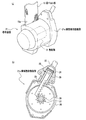
この第2プリテンショナ7として、例えば、図2に示す巻取装置21を用いることができる。この巻取装置21は、図2(a)に示すとおり、肩ベルト部10の一端10aが巻回される巻取軸31と、この巻取軸31に連結され、巻取軸31を瞬間的に回転駆動して肩ベルト部10を巻き取る瞬間巻取駆動部21aとを備えるものである。
瞬間巻取駆動部21aは、図2(b)の断面図に示すとおり、圧縮空気または高圧ガスが通るガス供給管22と、このガス供給管22に連結したシリンダ23と、このシリンダ23内に移動自在に収納されたピストン24と、このピストン24に一体に設けられたラック25と、このラック25に噛み合うピニオン26と、このピニオン26と一体的に回転するとともに巻取軸31(図2(a)参照)に複数のギヤを介して連結した回転軸27とを備える。これらのピニオン26、複数のギヤ及び回転軸27は、ケース28内に収納される。また、シリンダ23内に吹込まれた圧縮空気または高圧ガスにより移動したピストン24及びラック25を押し戻すために、ピストン24とケース28との間にリターンスプリング29が介装されている。
As the second pretensioner 7, for example, a winding
As shown in the sectional view of FIG. 2B, the instantaneous winding drive unit 21 a includes a
この巻取装置21は、ガス供給管22を通じてガス供給部(図示せず)から供給される圧縮空気または高圧ガスによって、肩ベルト部10を巻取軸31に巻き取って第2張力を発生させるものである。
The winding
衝突予知手段3は、車両Cの前部に配置され、自車両と、前方車両等の障害物との衝突が生ずる可能性を検知するものであり、例えば、レーザ、レーダ、超音波センサ等の非接触型距離センサによって所定時間毎に自車と障害物との間の距離を計測する装置を用いることができる。非接触型距離センサは、車両前部のバンパ等に埋設すれば前方の障害物の検知に有効であり、1つに限らず複数を衝突が予想される方向の車体面に配置することが好ましい。 The collision predicting means 3 is arranged at the front part of the vehicle C and detects the possibility of collision between the host vehicle and an obstacle such as a preceding vehicle. For example, a laser, radar, ultrasonic sensor, etc. A device that measures the distance between the vehicle and the obstacle every predetermined time by a non-contact type distance sensor can be used. If the non-contact type distance sensor is embedded in a bumper or the like at the front of the vehicle, it is effective for detecting obstacles ahead, and it is preferable to arrange not only one but a plurality on the body surface in the direction in which a collision is expected. .
この衝突予知手段3において、所定時間毎に計測される自車と障害物との距離の時間的変化から相対速度を計算する。そして、距離を相対速度で除算して衝突までの時間を計算する。該時間が予め設定された所定時間(しきい値)以下なら、衝突の可能性があるとして衝突予知の検知信号を出力する。この衝突予知の検知信号は、シートベルトプリテンショナ8に設けられたプリテンショナ制御手段14に入力され、プリテンショナ制御手段14において第1プリテンショナ6の作動が必要と判断されると、第1プリテンショナ6に指令信号が出力される。 In this collision prediction means 3, the relative speed is calculated from the temporal change in the distance between the host vehicle and the obstacle measured every predetermined time. Then, the distance to the collision is calculated by dividing the distance by the relative speed. If this time is less than or equal to a predetermined time (threshold value) set in advance, a collision prediction detection signal is output because there is a possibility of collision. This collision prediction detection signal is input to the pretensioner control means 14 provided in the seat belt pretensioner 8, and when the pretensioner control means 14 determines that the operation of the first pretensioner 6 is necessary, the first pretensioner 6 is operated. A command signal is output to the tensioner 6.
また、車両挙動検知手段4は、車両Cの前後方向および横方向の挙動を検知し、車両Cの急加減速、横すべり、回転、急操舵等による車両挙動の異常を検知するものである。この車両挙動検知手段4として、車体の前後方向および横方向の加速度を検知する加速度センサを用いることができる。この加速度センサによって、車体加速度の大きさおよび方向、変化率等を検知して、所定のしきい値と比較対照することによって車両挙動の異常を検知することができる。この加速度センサとして、車両Cの各種制御を行う装置に装備されているものを利用することができる。例えば、ブレーキ信号あるいは車両ブレーキング時の減速度を検知して、ブレーキの作動を制御するABS(アンチ・ロック・ブレーキシステム)に装備される加速度センサを利用してもよい。 Further, the vehicle behavior detection means 4 detects the behavior of the vehicle C in the front-rear direction and the lateral direction, and detects abnormality in the vehicle behavior due to sudden acceleration / deceleration, side slip, rotation, sudden steering, etc. of the vehicle C. As the vehicle behavior detecting means 4, an acceleration sensor that detects accelerations in the longitudinal direction and the lateral direction of the vehicle body can be used. This acceleration sensor detects the magnitude and direction of the vehicle body acceleration, the rate of change, and the like, and can detect an abnormality in the vehicle behavior by comparing with a predetermined threshold value. As the acceleration sensor, a sensor equipped in a device that performs various controls of the vehicle C can be used. For example, an acceleration sensor provided in an ABS (anti-lock brake system) that detects the brake signal or deceleration during vehicle braking and controls the operation of the brake may be used.
この車両挙動検知手段4においては、車両挙動の異常を検知すると、その車両挙動の異常に関する検知信号がプリテンショナ制御手段14に出力される。
When the vehicle behavior detection unit 4 detects an abnormality in the vehicle behavior, a detection signal related to the abnormality in the vehicle behavior is output to the
衝突検知手段5は、自車両と他車両等の障害物との衝突を検知するものであり、例えば、車体中央、前席左右、後席左右等に配置され、車両が障害物に衝突して所定のしきい値以上の加速度が車体に作用すると、この加速度を検知して閉じる接点を有するセンサを用いることができる。この接点が閉じることによって、プリテンショナ制御手段14に衝突の検知信号(図3中、衝突検知信号)を出力するものである。 The collision detection means 5 detects a collision between the host vehicle and an obstacle such as another vehicle. For example, the collision detection means 5 is arranged at the center of the vehicle body, left and right of the front seat, left and right of the rear seat, and the vehicle collides with the obstacle. When acceleration equal to or greater than a predetermined threshold acts on the vehicle body, a sensor having a contact that detects and closes the acceleration can be used. When this contact is closed, a collision detection signal (collision detection signal in FIG. 3) is output to the pretensioner control means 14.
また、プリテンショナ制御手段14は、前記第1プリテンショナ6と前記第2プリテンショナ7の作動を制御するものであり、衝突予知手段3からの衝突予知の検知信号、および車両挙動検知手段4からの車両挙動に関する検知信号が入力され、その衝突予知の検知信号の入力の有無、車両挙動の異常に関する検知信号の入力の有無に応じて、第1プリテンショナ6による第1張力F1の作動力および作動過程を制御する。そして、次に、衝突検知手段5から衝突の検知信号が入力されると、プリテンショナ制御手段14は、第2プリテンショナ7に指令信号を出力して第2プリテンショナ7を作動させ第2張力F2を発生させ、乗員の2次拘束がなされる(2次拘束段階)。 Further, the pretensioner control means 14 controls the operation of the first pretensioner 6 and the second pretensioner 7. From the collision prediction detection signal from the collision prediction means 3 and the vehicle behavior detection means 4. The detection signal related to the vehicle behavior of the first pretensioner 6 is applied according to the presence / absence of the detection signal of the collision prediction and the presence / absence of the detection signal related to the abnormality of the vehicle behavior. Control the operation process. Then, when a collision detection signal is input from the collision detection means 5, the pretensioner control means 14 outputs a command signal to the second pretensioner 7 to operate the second pretensioner 7 and the second tension. F2 is generated and the passenger is secondarily restrained (secondary restraint stage).
次に、以上に述べたシートベルト装置1の作動機構を説明する。
図3は、シートベルト装置1の作動機構を説明するためのブロック図である。
このシートベルト装置1において、衝突予知手段3は、所定時間毎に自車と障害物との距離を計測し、その時間的変化から自車と障害物との相対速度を計算する。そして、距離を相対速度で除算して衝突までの時間を計算し、その計算された時間が予め設定された所定時間(しきい値)以下であれば、衝突の可能性があるとして衝突予知の検知信号をシートベルトプリテンショナ8のプリテンショナ制御手段14に出力する。
Next, the operation mechanism of the seat belt device 1 described above will be described.
FIG. 3 is a block diagram for explaining an operation mechanism of the seat belt device 1.
In this seat belt device 1, the collision prediction means 3 measures the distance between the own vehicle and the obstacle every predetermined time, and calculates the relative speed between the own vehicle and the obstacle from the temporal change. Then, the time until the collision is calculated by dividing the distance by the relative speed. If the calculated time is equal to or less than a predetermined time (threshold value) set in advance, it is determined that there is a possibility of a collision. The detection signal is output to the pretensioner control means 14 of the seat belt pretensioner 8.
一方、車両挙動検知手段4は、車体の前後方向に加わる車体加速度によって車両挙動を検知して、その車両挙動に関する検知信号をシートベルトプリテンショナ8に設けられたプリテンショナ制御手段14に入力する。ここで、車体加速度が所定のしきい値以上となり、また、車体加速度が所定の変化率以上で変化した場合、車両挙動の異常の検知信号をプリテンショナ制御手段14に入力する。 On the other hand, the vehicle behavior detection means 4 detects the vehicle behavior based on the vehicle body acceleration applied in the longitudinal direction of the vehicle body, and inputs a detection signal related to the vehicle behavior to the pretensioner control means 14 provided in the seat belt pretensioner 8. Here, when the vehicle body acceleration becomes equal to or higher than a predetermined threshold value and the vehicle body acceleration changes at a predetermined change rate or higher, an abnormality detection signal for vehicle behavior is input to the pretensioner control means 14.
プリテンショナ制御手段14は、衝突予知手段3からの衝突予知の検知信号の入力の有無、および車両挙動検知手段4からの車両挙動の異常に関する検知信号の入力の有無に応じて、第1プリテンショナ6による第1張力の作動力および作動過程を制御する。例えば、プリテンショナ制御手段14は、下記の表1に示すCase1〜Case4に応じて、第1プリテンショナ6の作動の要否および作動過程を判断して、第1プリテンショナ6に第1張力F1(F12,F13,F14)の作動力および作動過程について指令信号を出力する。ここで、F12<F13<F14とする。例えば、張力F12およびF13の大きさは、それぞれ張力F14の40〜60%および60〜80%の大きさに設定される。

(1)Case1:衝突予知手段3から衝突予知の検知信号が入力されず(NO)、車両挙動検知手段4からも車両挙動の異常に関する検知信号が入力されない(NO)場合には、プリテンショナ制御手段14は、第1プリテンショナ6に指令信号を出力しない。このとき、乗員には第1張力が作用していない。 (1) Case 1: When a collision prediction detection signal is not input from the collision prediction means 3 (NO) and a detection signal regarding abnormality in vehicle behavior is not input from the vehicle behavior detection means 4 (NO), pretensioner control is performed. The means 14 does not output a command signal to the first pretensioner 6. At this time, the first tension is not acting on the occupant.
(2)Case2:衝突予知手段3から衝突予知の検知信号が入力され(YES)、車両挙動検知手段4から車両挙動の異常に関する検知信号が入力されない(NO)場合には、プリテンショナ制御手段14は、第1プリテンショナ6に指令信号を送信して、図4(a)に示すように、第1張力F12を作動させる。 (2) Case 2: When a collision prediction detection signal is input from the collision prediction means 3 (YES) and no detection signal regarding abnormality in vehicle behavior is input from the vehicle behavior detection means 4 (NO), the pretensioner control means 14 Transmits a command signal to the first pretensioner 6 to actuate the first tension F12 as shown in FIG.
(3)Case3:衝突予知手段3から衝突予知の検知信号が入力されず(NO)、車両挙動検知手段4から車両挙動の異常に関する検知信号が入力された(YES)場合には、プリテンショナ制御手段14は、第1プリテンショナ6に指令信号を出力して、図4(b)に示すように、第1張力F13を作動させる。 (3) Case 3: Pre-tensioner control when a collision prediction detection signal is not input from the collision prediction means 3 (NO) and a detection signal related to an abnormality in vehicle behavior is input from the vehicle behavior detection means 4 (YES) The means 14 outputs a command signal to the first pretensioner 6 to operate the first tension F13 as shown in FIG. 4 (b).
(4)Case4:衝突予知手段3から衝突予知の検知信号が入力され(YES)、車両挙動検知手段4からも車両挙動の異常に関する検知信号が入力された(YES)場合には、プリテンショナ制御手段14は、第1プリテンショナ6に指令信号を送信して、図4(c)に示すように、第1張力F14を作動させる。 (4) Case 4: When a collision prediction detection signal is input from the collision prediction means 3 (YES) and a detection signal related to an abnormality in vehicle behavior is also input from the vehicle behavior detection means 4 (YES), pretensioner control The means 14 transmits a command signal to the first pretensioner 6 to actuate the first tension F14 as shown in FIG. 4 (c).
プリテンショナ制御手段14から指令信号が入力された第1プリテンショナ6は、駆動手段によって巻取軸を回転駆動させてウェビングWを巻き取り、図4(a)〜図4(c)に示すように、第1張力F1(F12,F13,F14)を発生させる。これによって、シートベルト2(腰ベルト部12および肩ベルト部10)が引き取られ、この第1張力F1(F12,F13,F14)によって、腰ベルト部12のたるみが完全に解消され、またタングプレート11を介して肩ベルト部10のたるみもある程度解消されるとともに、座席Sに着座している乗員が1次拘束される(1次拘束段階)。
The first pretensioner 6 to which the command signal is input from the pretensioner control means 14 takes up the webbing W by rotating the take-up shaft by the drive means, as shown in FIGS. 4 (a) to 4 (c). Then, the first tension F1 (F12, F13, F14) is generated. As a result, the seat belt 2 (the waist belt portion 12 and the shoulder belt portion 10) is taken up, and the slack of the waist belt portion 12 is completely eliminated by the first tension F1 (F12, F13, F14), and the
また、プリテンショナ制御手段14は、前記Case2またはCase3の段階、すなわち、張力F12による拘束状態または張力F13による拘束状態のいずれかの状態にあるときに、さらに、衝突予知手段3からの衝突予知の検知信号または車両挙動検知手段4からの車両挙動の異常に関する検知信号が入力され、Case4の状態となったとき、そのCase4に応じた第1張力F14を作動させる指令信号を第1プリテンショナ6に出力する。これによって、図5(a)に示すようにCase2の段階(F12)からCase4の段階(F14)への移行、また、図5(b)に示すようにCase3の段階(F13)からCase4の段階(F14)への移行を行うことによって、衝突予知および車両挙動の状況に応じて、より適正な第1張力による乗員の拘束を行うことができる。このように、衝突予知手段3による衝突予知の検出信号の有無と車両挙動検知手段4からの車両挙動に関する検知信号の有無とによって、第1プリテンショナ6によってシートベルトのウェビングWを引き取る張力の大きさを制御し、さらに、Case2からCase4への作動タイミング、またはCase3からCase4への作動タイミング、すなわち、張力F12からF14への張力の切り替え、あるいは張力F13から張力F14への切り替えを行う時期を、プリテンショナ制御手段14によって適正に制御するようにすれば、衝突に備えてより適切に乗員を拘束することができる。
Further, when the pretensioner control means 14 is in the
一方、衝突検知手段5は、車両が障害物に衝突して、所定のしきい値以上の加速度が車体に作用すると、車体中央、前席左右、後席左右等に配置された個々のセンサがその加速度を検知して接点を閉じ、この接点が閉じることによって、シートベルトプリテンショナ8のプリテンショナ制御手段14に衝突の検知信号を出力する。 On the other hand, when the vehicle collides with an obstacle and an acceleration of a predetermined threshold value or more acts on the vehicle body, the collision detection means 5 has individual sensors arranged at the vehicle body center, front seat left and right, rear seat left and right, etc. The acceleration is detected and the contact is closed. When this contact is closed, a collision detection signal is output to the pretensioner control means 14 of the seat belt pretensioner 8.
プリテンショナ制御手段14は、衝突を検知した衝突検知手段5から衝突の検知信号が入力されると、シートベルトプリテンショナ8の第1プリテンショナ6に指令信号を出力して第1張力(F12,F13,F14)を解除させるとともに、第2プリテンショナ7に指令信号を出力して第2プリテンショナ7を作動させる。プリテンショナ制御手段14から指令信号が入力された第2プリテンショナ7は、急速巻取駆動装置を瞬間的に回転駆動して肩ベルト部10のウェビングWを巻き取って、図6に示すように、第1張力による1次拘束段階に続いて第2張力F2を発生させ、車両衝突時に乗員の拘束を行う(2次拘束段階)。このとき、プリテンショナ制御手段14は、前記第1張力の作動過程に応じて、前記第2張力を作動させる作動タイミングを制御する。第2張力F2の作動タイミングは、衝突検知→第1プリテンショナ6による第1張力F1(F12,F13,F14)の解除→第2プリテンショナ7の作動による第2張力F2の発生の順序で行われる。
When the collision detection signal is input from the collision detection unit 5 that has detected the collision, the
このとき、プリテンショナ制御手段14は、第1プリテンショナ6による第1張力F1(F12,F13,F14)の作動の解除、第2プリテンショナ7による第2張力F2の作動タイミングを制御することが好ましい。すなわち、Case2、Case3、またはCase4における1次拘束段階から張力の緩和段階を経て2次拘束段階へ移行する、またはCase1の非拘束段階から2次拘束段階へ移行するに際して、第2プリテンショナ7による第2張力F2の作動タイミングを制御する。例えば、下記の場合に応じて、第2張力F2の作動タイミングを制御する。
(1)Case1の段階から衝突が検知された場合は、第1張力F1が作用していない状態から第2張力F2が作用する2次拘束段階へ移行する。
(2)Case2の段階から衝突が検知された場合は、張力F12が作用している状態から第2張力F2が作用する2次拘束段階へ移行する。
(3)Case3の段階から衝突が検知された場合は、張力F13が作用している段階から第2張力F2が作用する2次拘束段階へ移行する。
(4)Case4の段階から衝突が検知された場合は、張力F14が作用している段階から第2張力F2が作用する2次拘束段階へ移行する。
(5)Case2またはCase3の段階からCase4の段階へ移行した後、衝突が検知された場合は、張力F14が作用している段階から第2張力が作用する2次拘束段階へ移行する。
At this time, the pretensioner control means 14 can control the release of the operation of the first tension F1 (F12, F13, F14) by the first pretensioner 6 and the operation timing of the second tension F2 by the second pretensioner 7. preferable. That is, when the transition from the primary restraint stage in
(1) When a collision is detected from the Case1 stage, the process proceeds from the state where the first tension F1 is not applied to the secondary restraint stage where the second tension F2 is applied.
(2) When a collision is detected from the Case2 stage, the state moves from the state in which the tension F12 is applied to the secondary restraint stage in which the second tension F2 is applied.
(3) When a collision is detected from the Case 3 stage, the stage shifts from the stage where the tension F13 is applied to the secondary restraint stage where the second tension F2 is applied.
(4) When a collision is detected from the Case4 stage, the stage shifts from the stage where the tension F14 is applied to the secondary constraint stage where the second tension F2 is applied.
(5) After a transition from the
なお、Case2、Case3またはCase4の段階で、衝突検知手段5によって所定時間、衝突が検知されない場合は、プリテンショナ制御手段14は、第2プリテンショナ7の作動の指令信号を出力せずに、第1プリテンショナ6の作動を解除して、シートベルト2による乗員の拘束を停止する。これによって、衝突または車両挙動の異常がない状態でシートベルト2によって乗員の運転操作が阻害されることなく、また、乗員がシートベルト装薬によって受ける違和感を最小限にすることができる。
When no collision is detected by the collision detection unit 5 for a predetermined time at the stage of
これらの5つの場合に応じて、プリテンショナ制御手段14は、第2プリテンショナ7の作動タイミングを制御する。例えば、第1張力F1が作動していない非拘束段階から衝突検知時t0から第2プリテンショナ7による第2張力F2の作動時期t1、および第1張力F1(F12,F13,F14)の作動している段階において、衝突検知時t0から第2プリテンショナ7による第2張力F2の作動時期t2,t3,t4,t5、までの時間T1、T2、T3、T4、T5をT1>T2>T3>T4>T5の順で短くする。すなわち、Case1<Case2<Case3<Case4の順で第2プリテンショナ7の作動タイミングを早くする(例えば、Case2:係数=0.9、Case3:係数=0.8、Case4:K=0.7)これによって、衝突の切迫性に応じて第2張力F2を適正に作動させて乗員を2次拘束して保護することができるとともに、前記第1張力F1(F12,F13,F14)から第2張力F2への移行時に乗員が受ける衝撃が緩和される。 Depending on these five cases, the pretensioner control means 14 controls the operation timing of the second pretensioner 7. For example, the operation timing t1 of the second tension F2 by the second pretensioner 7 and the operation of the first tension F1 (F12, F13, F14) from the collision detection time t0 from the non-restraining stage where the first tension F1 is not operating. In the stage, the times T1, T2, T3, T4, T5 from the time t0 when the collision is detected to the operation timing t2, t3, t4, t5 of the second tension F2 by the second pretensioner 7 are T1> T2> T3>. Shorten in the order of T4> T5. That is, the operation timing of the second pretensioner 7 is advanced in the order of Case1 <Case2 <Case3 <Case4 (for example, Case2: coefficient = 0.9, Case3: coefficient = 0.8, Case4: K = 0.7). As a result, the second tension F2 can be appropriately actuated according to the impending nature of the collision to protect the occupant by being secondarily restrained, and the second tension can be protected from the first tension F1 (F12, F13, F14). The impact received by the occupant during the transition to F2 is mitigated.
このようなシートベルト装置1の作動を図7を用いて説明すると、まず、(a)通常走行時には、座席Sに着座した乗員に装着したシートベルト2は、肩ベルト部10および腰ベルト部12にウェビングWのたるみを解消する張力TWが第1プリテンショナ6または第2プリテンショナ7によって作用している。
そして、衝突が予知された場合((b)衝突予知時)第1プリテンショナ6が作動して第1張力F1によりシートベルト2が引き取られて乗員が一次拘束される(1次拘束段階)。
次に、衝突が検知された場合((c)衝突検知時)、第2プリテンショナ7が作動して第2張力F2によりシートベルトが引き取られて乗員が2次拘束される(2次拘束段階)。
The operation of the seat belt apparatus 1 will be described with reference to FIG. 7. First, (a) during normal running, the
When a collision is predicted ((b) at the time of a collision prediction), the first pretensioner 6 is actuated, the
Next, when a collision is detected ((c) at the time of collision detection), the second pretensioner 7 is actuated, the seat belt is taken up by the second tension F2, and the occupant is secondarily restrained (secondary restraint stage). ).
このように、第1プリテンショナ6による1次拘束段階における第1張力F1(F12,F13,F14)の作動過程、および第2プリテンショナ7による2次拘束段階における第2張力F2の作動タイミングを制御することによって、衝突予知および衝突検知の段階に応じて乗員の下半身の移動が有効に防止されるとともに、肩ベルト部8もたるみが予め解消されているから、上半身の移動は少なく、エアバッグ等との協働により効果的に乗員が保護される。さらに、衝突予知手段、車両挙動検知手段の検知信号に基づいて第1プリテンショナが作動している状態においても、運転者が衝突回避操作等の運転操作を適切に行うことができる。 Thus, the operation process of the first tension F1 (F12, F13, F14) in the primary restraint stage by the first pretensioner 6 and the operation timing of the second tension F2 in the secondary restraint stage by the second pretensioner 7 are as follows. By controlling the movement, the lower body of the occupant is effectively prevented from moving in accordance with the stage of collision prediction and collision detection, and the shoulder belt portion 8 is also eliminated from slack beforehand. The passengers are effectively protected in cooperation with the Furthermore, even when the first pretensioner is operating based on detection signals from the collision prediction means and the vehicle behavior detection means, the driver can appropriately perform driving operations such as a collision avoidance operation.
1 シートベルト装置
2 シートベルト
3 衝突予知手段
4 車両挙動検知手段
5 衝突検知手段
6 第1プリテンショナ
7 第2プリテンショナ
8 シートベルトプリテンショナ
9 肩ベルトアンカ
10 肩ベルト部
11 タングプレート
12 腰ベルト部
13 バックル
14 プリテンショナ制御手段
S 座席
W ウェビング
DESCRIPTION OF SYMBOLS 1
Claims (4)
前記シートベルトプリテンショナは、前記シートベルトを第1張力で引き取って前記乗員を1次拘束する第1のプリテンショナと、前記シートベルトを第2張力で引き取って前記乗員を2次拘束する第2のプリテンショナと、を制御するプリテンショナ制御手段を備え、
前記プリテンショナ制御手段は、前記衝突予知手段による衝突予知に関する検知信号と、前記車両挙動検知手段による車両挙動に関する検知信号のうち、前記衝突予知手段からのみ検知信号が入力された場合は第1張力F12を前記第1プリテンショナに作動させ、前記車両挙動検知手段からのみ検知信号が入力された場合は第1張力F13を前記第1プリテンショナに作動させ、前記衝突予知手段および前記車両挙動検知手段の両方から検知信号が入力された場合は第1張力F14を前記第1プリテンショナに作動させるよう制御し、前記第1張力はF12<F13<F14とすることを特徴とする車両のシートベルト装置。 A seat belt to be attached to an occupant seated on a seat provided in the vehicle, a collision prediction means for predicting a collision between the vehicle and an obstacle, a vehicle behavior detection means for detecting the behavior of the vehicle, and the collision detection A vehicle seat belt device comprising a collision detection means and a seat belt pretensioner,
The seatbelt pretensioner has a first pretensioner that pulls the seatbelt with a first tension and primarily restrains the occupant, and a second pretensioner that pulls the seatbelt with a second tension and secondarily restrains the occupant. And a pretensioner control means for controlling the pretensioner ,
The pretensioner control means has a first tension when a detection signal is inputted only from the collision prediction means, out of a detection signal related to collision prediction by the collision prediction means and a detection signal related to vehicle behavior by the vehicle behavior detection means. F12 is operated to the first pretensioner, and when a detection signal is inputted only from the vehicle behavior detecting means, the first tension F13 is operated to the first pretensioner, and the collision prediction means and the vehicle behavior detecting means are operated. When a detection signal is input from both of them, the first tension F14 is controlled to be operated by the first pretensioner, and the first tension is F12 <F13 <F14. .
Priority Applications (1)
| Application Number | Priority Date | Filing Date | Title |
|---|---|---|---|
| JP2003378743A JP4133749B2 (en) | 2003-11-07 | 2003-11-07 | Vehicle seat belt device |
Applications Claiming Priority (1)
| Application Number | Priority Date | Filing Date | Title |
|---|---|---|---|
| JP2003378743A JP4133749B2 (en) | 2003-11-07 | 2003-11-07 | Vehicle seat belt device |
Publications (2)
| Publication Number | Publication Date |
|---|---|
| JP2005138756A JP2005138756A (en) | 2005-06-02 |
| JP4133749B2 true JP4133749B2 (en) | 2008-08-13 |
Family
ID=34689027
Family Applications (1)
| Application Number | Title | Priority Date | Filing Date |
|---|---|---|---|
| JP2003378743A Expired - Fee Related JP4133749B2 (en) | 2003-11-07 | 2003-11-07 | Vehicle seat belt device |
Country Status (1)
| Country | Link |
|---|---|
| JP (1) | JP4133749B2 (en) |
Families Citing this family (5)
| Publication number | Priority date | Publication date | Assignee | Title |
|---|---|---|---|---|
| JP4757726B2 (en) * | 2005-08-18 | 2011-08-24 | 本田技研工業株式会社 | Vehicle seat belt device |
| JP2007050852A (en) * | 2005-08-19 | 2007-03-01 | Toyota Motor Corp | Vehicle occupant protection system |
| WO2015159763A1 (en) * | 2014-04-14 | 2015-10-22 | 株式会社小糸製作所 | Foreign material removal device |
| JP7167745B2 (en) | 2019-02-04 | 2022-11-09 | トヨタ自動車株式会社 | vehicle seat belt device |
| JP7259693B2 (en) * | 2019-10-09 | 2023-04-18 | トヨタ自動車株式会社 | vehicle occupant restraint system |
-
2003
- 2003-11-07 JP JP2003378743A patent/JP4133749B2/en not_active Expired - Fee Related
Also Published As
| Publication number | Publication date |
|---|---|
| JP2005138756A (en) | 2005-06-02 |
Similar Documents
| Publication | Publication Date | Title |
|---|---|---|
| US5748477A (en) | Vehicle collision control system | |
| CN107521448B (en) | Method for controlling operation of safety device of vehicle and control device | |
| JP4591750B2 (en) | Vehicle occupant protection device | |
| CN108454560B (en) | Variable force limiter control system for vehicle | |
| JP4444181B2 (en) | Crew restraint system | |
| JP2002019555A (en) | Occupant crash protection device | |
| KR100581044B1 (en) | Occupant restraint system | |
| JP4088240B2 (en) | Vehicle seat belt device | |
| JP4133749B2 (en) | Vehicle seat belt device | |
| JP4682351B2 (en) | Vehicle occupant restraint system | |
| JP3951959B2 (en) | Vehicle seat belt device | |
| JP2018176845A (en) | Seat belt device | |
| JP3711974B2 (en) | Vehicle seat belt device | |
| JP4141967B2 (en) | Vehicle travel safety device | |
| JP4290573B2 (en) | Vehicle travel safety device | |
| JP2005263071A (en) | Crew protection device | |
| JP4290575B2 (en) | Vehicle travel safety device | |
| JP4290574B2 (en) | Vehicle travel safety device | |
| JP4290571B2 (en) | Vehicle travel safety device | |
| JP4722619B2 (en) | Vehicle seat belt device | |
| JP4722399B2 (en) | Vehicle travel safety device | |
| JP4409297B2 (en) | Vehicle travel safety device | |
| JP4290572B2 (en) | Vehicle travel safety device | |
| JP4290570B2 (en) | Vehicle travel safety device | |
| KR100534164B1 (en) | Active safety seat belt system and the method |
Legal Events
| Date | Code | Title | Description |
|---|---|---|---|
| A621 | Written request for application examination |
Free format text: JAPANESE INTERMEDIATE CODE: A621 Effective date: 20051202 |
|
| A977 | Report on retrieval |
Free format text: JAPANESE INTERMEDIATE CODE: A971007 Effective date: 20080215 |
|
| A131 | Notification of reasons for refusal |
Free format text: JAPANESE INTERMEDIATE CODE: A131 Effective date: 20080219 |
|
| A521 | Written amendment |
Free format text: JAPANESE INTERMEDIATE CODE: A523 Effective date: 20080421 |
|
| TRDD | Decision of grant or rejection written | ||
| A01 | Written decision to grant a patent or to grant a registration (utility model) |
Free format text: JAPANESE INTERMEDIATE CODE: A01 Effective date: 20080527 |
|
| A01 | Written decision to grant a patent or to grant a registration (utility model) |
Free format text: JAPANESE INTERMEDIATE CODE: A01 |
|
| A61 | First payment of annual fees (during grant procedure) |
Free format text: JAPANESE INTERMEDIATE CODE: A61 Effective date: 20080602 |
|
| FPAY | Renewal fee payment (event date is renewal date of database) |
Free format text: PAYMENT UNTIL: 20110606 Year of fee payment: 3 |
|
| R150 | Certificate of patent or registration of utility model |
Free format text: JAPANESE INTERMEDIATE CODE: R150 |
|
| FPAY | Renewal fee payment (event date is renewal date of database) |
Free format text: PAYMENT UNTIL: 20110606 Year of fee payment: 3 |
|
| FPAY | Renewal fee payment (event date is renewal date of database) |
Free format text: PAYMENT UNTIL: 20130606 Year of fee payment: 5 |
|
| FPAY | Renewal fee payment (event date is renewal date of database) |
Free format text: PAYMENT UNTIL: 20130606 Year of fee payment: 5 |
|
| FPAY | Renewal fee payment (event date is renewal date of database) |
Free format text: PAYMENT UNTIL: 20140606 Year of fee payment: 6 |
|
| LAPS | Cancellation because of no payment of annual fees |