JP4119644B2 - Pneumatic tire - Google Patents
Pneumatic tire Download PDFInfo
- Publication number
- JP4119644B2 JP4119644B2 JP2001371236A JP2001371236A JP4119644B2 JP 4119644 B2 JP4119644 B2 JP 4119644B2 JP 2001371236 A JP2001371236 A JP 2001371236A JP 2001371236 A JP2001371236 A JP 2001371236A JP 4119644 B2 JP4119644 B2 JP 4119644B2
- Authority
- JP
- Japan
- Prior art keywords
- tire
- edge
- side edge
- width direction
- circumferential direction
- Prior art date
- Legal status (The legal status is an assumption and is not a legal conclusion. Google has not performed a legal analysis and makes no representation as to the accuracy of the status listed.)
- Expired - Lifetime
Links
- 230000007423 decrease Effects 0.000 claims description 11
- 238000012360 testing method Methods 0.000 description 86
- 230000001429 stepping effect Effects 0.000 description 52
- 238000011156 evaluation Methods 0.000 description 9
- 230000000694 effects Effects 0.000 description 6
- 238000013461 design Methods 0.000 description 3
- 238000000034 method Methods 0.000 description 3
- 238000012545 processing Methods 0.000 description 3
- 238000005516 engineering process Methods 0.000 description 2
- 238000005259 measurement Methods 0.000 description 2
- 238000005096 rolling process Methods 0.000 description 2
- 238000013459 approach Methods 0.000 description 1
- 230000003247 decreasing effect Effects 0.000 description 1
- 238000010586 diagram Methods 0.000 description 1
- 238000004519 manufacturing process Methods 0.000 description 1
Images


Classifications
-
- B—PERFORMING OPERATIONS; TRANSPORTING
- B60—VEHICLES IN GENERAL
- B60C—VEHICLE TYRES; TYRE INFLATION; TYRE CHANGING; CONNECTING VALVES TO INFLATABLE ELASTIC BODIES IN GENERAL; DEVICES OR ARRANGEMENTS RELATED TO TYRES
- B60C11/00—Tyre tread bands; Tread patterns; Anti-skid inserts
- B60C11/03—Tread patterns
- B60C11/13—Tread patterns characterised by the groove cross-section, e.g. for buttressing or preventing stone-trapping
- B60C11/1376—Three dimensional block surfaces departing from the enveloping tread contour
- B60C11/1384—Three dimensional block surfaces departing from the enveloping tread contour with chamfered block corners
-
- B—PERFORMING OPERATIONS; TRANSPORTING
- B60—VEHICLES IN GENERAL
- B60C—VEHICLE TYRES; TYRE INFLATION; TYRE CHANGING; CONNECTING VALVES TO INFLATABLE ELASTIC BODIES IN GENERAL; DEVICES OR ARRANGEMENTS RELATED TO TYRES
- B60C11/00—Tyre tread bands; Tread patterns; Anti-skid inserts
- B60C11/03—Tread patterns
- B60C11/13—Tread patterns characterised by the groove cross-section, e.g. for buttressing or preventing stone-trapping
- B60C11/1376—Three dimensional block surfaces departing from the enveloping tread contour
- B60C11/1392—Three dimensional block surfaces departing from the enveloping tread contour with chamfered block edges
Landscapes
- Engineering & Computer Science (AREA)
- Mechanical Engineering (AREA)
- Tires In General (AREA)
Description
【0001】
【発明の属する技術分野】
本発明は、空気入りタイヤに係り、特に、他性能を損なうことなくタイヤ騒音の改良を達成しうる空気入りタイヤに関する。
【0002】
【従来の技術】
雨天時の走行を考慮する目的から、タイヤトレッドパターンが存在し、その多くはタイヤ周方向及びタイヤ幅方向に延びる溝を持つため、トレッドにはブロックと呼ばれる陸部が存在する。
【0003】
しかし、このブロックが存在するためにパターンノイズが発生することが知られている。
【0004】
この点に関する従来技術は、大きく2点に分れる。
【0005】
1点目は、単一のブロックの加わる入力を時間方向に引き伸ばす目的からラグ溝のタイヤ幅方向に対する角度を大きく設定する方法である。
【0006】
2点目は、ブロックの周方向長さに種類を持たせたり、更にその位相をタイヤ内でずらすことにより他のブロックとの関係を用いて単一周波数にピークを持たせない方法である。
【0007】
これらの技術は、主に2次元的考えによって開発されており、その歴史も長い。
【0008】
【発明が解決しようとする課題】
しかしながら、近年の静粛性が多く求められる自動車においては、上記従来技術の効果は充分ではなく、また、他性能との兼ね合いから前記方法を用いて騒音だけを重視した設計も困難であるので、新たな技術が求められている。
【0009】
特に、単一のブロックにおいては、ラグ溝のタイヤ幅方向に対する角度を大きく設定することで(即ち、パターンデザインの変更)、例えば、ブロックの形状が周方向に細長い平行四辺形に近づきブロック剛性の低下が生じると共に、偏摩耗性との背反もある点が指摘されている。
【0010】
本発明は上記事実を考慮して、ブロックパターンの基調のデザインを変えずに騒音を改良できる空気入りタイヤを提供することが目的である。
【0011】
【課題を解決するための手段】
請求項1に記載の発明は、タイヤ周方向に沿って延びる複数の周方向溝と、前記周方向溝に交差する複数の溝とによって区画された複数のブロックをトレッドに備えた空気入りタイヤであって、タイヤ幅方向最外側のブロックのタイヤ赤道面側の端縁には、踏み込み側の端縁または蹴り出し側の端縁の何れか一方にタイヤ外輪郭に沿った高地部が設けられ、踏み込み側の端縁または蹴り出し側の端縁の何れか他方に前記高地部から離れるにしたがってブロック高さが徐々に低くなる第1の低地部が設けられており、タイヤ幅方向最外側のブロックの接地端では、全てがタイヤ外輪郭に沿った高地部とされており、前記タイヤ幅方向最外側のブロックのタイヤ赤道面側の端縁における前記高地部の最も高い部分から前記第1の低地部の最も低い部分までのブロック高さ方向の落し寸法をHa、前記タイヤ幅方向最外側のブロックのタイヤ赤道面側の端縁におけるブロック高さをCとしたときに、Ha/Cが0.02以上0.25以下である、ことを特徴としている。
【0012】
次に、請求項1に記載の空気入りタイヤの作用を説明する。
【0013】
先ず最初に、図18に示すような高さが一定の通常のショルダーブロック100については、寸法A,Bで規定される接地領域102(斜線部分)が存在する(なお、符号104は接地端、矢印L方向及び矢印R方向はタイヤ幅方向、矢印A方向はタイヤ回転方向を示している。)。
【0014】
この接地領域102は、あくまで接地直下付近のものであり、実際には、ショルダーブロック100が入力を受ける、及び入力が開放される踏み蹴り挙動時には、周方向に対して徐々に踏み込み、蹴り出しが行われる。
【0015】
騒音入力は、動的に大きく変動する部分で大きいので、騒音を低減する上ではこの部分が重要である。
【0016】
このとき、寸法Bで規定されたショルダーブロック100の踏み込み側の端縁(エッジ)100Aは、ショルダーブロック100の踏面が平坦な場合では接地形状の影響を受けてほぼ同時に踏み込みを行うことになるので、単一の大きなピークを持った力が端縁を介してタイヤに伝達され、振動騒音の入力となる。
【0017】
請求項1に記載のタイヤ幅方向最外側のブロックでは、タイヤ赤道面側の端縁において、踏み込み側の端縁または蹴り出し側の端縁の何れか他方にブロック高さが徐々に低くなる第1の低地部が設けられている。
【0018】
このため、第1の低地部が設けられた側の踏み込み側の端縁または蹴り出し側の端縁では、タイヤ赤道面側の端縁からタイヤ幅方向外側へ向けてブロック高さが徐々に高くなる。
【0019】
したがって、タイヤ赤道面側の端縁の踏み込み側に第1の低地部が設けられている場合には、踏み込み時に、踏み込み縁が路面に対して徐々に接触することになり、踏み込みの挙動による力のピークを時間方向に分散でき、これによりタイヤ幅方向最外側のブロックより発生する騒音のレベルを低く抑えることができる。
【0020】
また、タイヤ赤道面側の端縁の蹴り出し側に第1の低地部が設けられている場合には、蹴り出し時に、蹴り出し縁が路面に対して徐々に離れることになり、蹴り出し挙動による力のピークを時間方向に分散でき、これによりタイヤ幅方向最外側のブロックより発生する騒音のレベルを低く抑えることができる。
【0021】
また、このタイヤ幅方向最外側のブロックにおいては、タイヤ幅方向外側の接地端の全てをタイヤ外輪郭に沿った高地部としたので、踏み込み縁または蹴り出し縁における接地部の高低差を最大限つけることができ、その端が接地する時間(または離れる時間)を最大限に引きのばすことができる。
また、Ha/Cを0.02以上0.25以下とすることにより、騒音レベルを十分に低減することができる。
【0022】
なお、ここでいう接地端とは、空気入りタイヤをJATMA YEAR BOOK(日本自動車タイヤ協会規格2001年度版)に規定されている標準リムに装着し、JATMA YEAR BOOKでの適用サイズ・プライレーティングにおける最大負荷能力(内圧−負荷能力対応表の太字荷重)に対応する空気圧(最大空気圧)の100%の内圧を充填し、最大負荷能力を負荷したときのものである。
【0023】
使用地又は製造地において、TRA規格、ETRTO規格が適用される場合は各々の規格に従う。
【0024】
請求項2に記載の発明は、互いに交差する複数の溝によって区画された複数のブロックをトレッドに備えた空気入りタイヤであって、タイヤ幅方向最外側のブロックの踏み込み側縁または蹴り出し側縁では、タイヤ外輪郭に沿った高地部と、前記高地部よりも低く前記高地部から離れるにしたがってブロック高さが徐々に低くなる第2の低地部とが設けられており、前記第2の低地部が設けられている前記タイヤ幅方向最外側のブロックの踏み込み側縁または蹴り出し側縁において、タイヤ赤道面側の端部から前記第2の低地部までのタイヤ幅方向に沿って計測した寸法をLd、前記タイヤ幅方向最外側のブロックの、タ イヤ赤道面側の端縁から接地端までのタイヤ幅方向に沿って計測した寸法をBとしたときに、Ld/Bが0.15以上0.75以下である、ことを特徴としている。
【0025】
次に、請求項2に記載の空気入りタイヤの作用を説明する。
【0026】
請求項2に記載の空気入りタイヤによれば、タイヤ幅方向最外側のブロックにおいて、踏み込み側縁または蹴り出し側縁では、タイヤ外輪郭に沿った高地部と、前記高地部よりも低く前記高地部から離れるにしたがってブロック高さが徐々に低くなる第2の低地部とが設けられているので、踏み込みの挙動、または蹴り出しの挙動による力のピークを時間方向に分散でき、これによりタイヤ幅方向最外側のブロックより発生する騒音のレベルを低く抑えることができる。
また、Ld/Bを0.15以上0.75以下とすることにより、騒音レベルを十分に低減することができる。
【0027】
請求項3に記載の発明は、互いに交差する複数の溝によって区画された複数のブロックをトレッドに備えた空気入りタイヤであって、タイヤ幅方向最外側のブロックのタイヤ赤道面側の端縁には、踏み込み側の端縁または蹴り出し側の端縁の何れか一方にタイヤ外輪郭に沿った高地部が設けられ、踏み込み側の端縁または蹴り出し側の端縁の何れか他方に前記高地部から離れるにしたがってブロック高さが徐々に低くなる第1の低地部が設けられており、タイヤ幅方向最外側のブロックの前記第1の低地部が設けられていない方の踏み込み側縁または蹴り出し側縁では、タイヤ外輪郭に沿った高地部と、前記高地部よりも低く前記高地部から離れるにしたがってブロック高さが徐々に低くなる第2の低地部とが設けられており、前記タイヤ幅方向最外側のブロックのタイヤ赤道面側の端縁における前記高地部の最も高い部分から前記第1の低地部の最も低い部分までのブロック高さ方向の落し寸法をHa、前記タイヤ幅方向最外側のブロックのタイヤ赤道面側の端縁におけるブロック高さをCとしたときに、Ha/Cが0.02以上0.25以下である、ことを特徴としている。
【0028】
次に、請求項3に記載の空気入りタイヤの作用を説明する。
【0029】
請求項3に記載の空気入りタイヤでは、タイヤ赤道面側の端縁の踏み込み側または蹴り出し側の何れか一方に第1の低地部を設け、踏み込み側の端縁または蹴り出し側の端縁の何れか他方に第2の低地部を設けたので、踏み込みの挙動による力のピークと、蹴り出しの挙動による力のピークの両方を時間方向に分散でき(即ち、請求項1に記載の作用と請求項2に記載の作用との両方の作用。)、これによりタイヤ幅方向最外側のブロックより発生する騒音のレベルを更に低く抑えることができる。
また、Ha/Cを0.02以上0.25以下とすることにより、騒音レベルを十分に低減することができる。
【0030】
請求項4に記載の発明は、請求項1または請求項3に記載の空気入りタイヤにおいて、前記タイヤ幅方向最外側のブロックのタイヤ赤道面側の端縁において、前記高地部の最も高い部分から前記第1の低地部の最も低い部分までのブロック高さ方向の落し寸法をHaとしたときに、Haが0.2mm以上2.5mm以下である、ことを特徴としている。
【0031】
次に、請求項4に記載の空気入りタイヤの作用を説明する。
【0032】
Haを0.2mm以上2.5mm以下とすることにより、騒音レベルを十分に低減することができる。
【0033】
【0034】
【0035】
【0036】
請求項5に記載の発明は、請求項2また3に記載の空気入りタイヤにおいて、前記第2の低地部の設けられた前記踏み込み側縁または前記蹴り出し側縁において、前記高地部の最も高い部分から前記第2の低地部の最も低い部分までのブロック高さ方向の落し寸法をHbとしたときに、Hbが0.2mm以上2.5mm以下である、ことを特徴としている。
【0037】
次に、請求項5に記載の空気入りタイヤの作用を説明する。
【0038】
Hbを0.2mm以上2.5mm以下とすることにより、騒音レベルを十分に低減することができる。
【0039】
請求項6に記載の発明は、請求項2、3、5の何れか1項に記載の空気入りタイヤにおいて、前記第2の低地部の設けられた前記踏み込み側縁または前記蹴り出し側縁において、前記高地部の最も高い部分から前記第2の低地部の最も低い部分までのブロック高さ方向の落し寸法をHb、前記タイヤ幅方向最外側のブロックのタイヤ赤道面側の端縁におけるブロック高さをCとしたときに、Hb/Cが0.02以上0.25以下である、ことを特徴としている。
【0040】
次に、請求項6に記載の空気入りタイヤの作用を説明する。
【0041】
Hb/Cを0.02以上0.25以下とすることにより、騒音レベルを十分に低減することができる。
【0042】
請求項7に記載の発明は、請求項1、3、4の何れか1項に記載の空気入りタイヤにおいて、前記第1の低地部の、タイヤ赤道面側の端縁からタイヤ幅方向外側へ計測したときの寸法をLaとしたときに、寸法Laが5mm以上である、ことを特徴としている。
【0043】
次に、請求項7に記載の空気入りタイヤの作用を説明する。
【0044】
Laを5mm以上とすることにより、騒音レベルを十分に低減することができる。
【0045】
請求項8に記載の発明は、請求項1、3、4、5、7の何れか1項に記載の空気入りタイヤにおいて、前記第1の低地部の、タイヤ赤道面側の端縁からタイヤ幅方向外側へ計測したときの寸法をLa、前記タイヤ幅方向最外側のブロックの、タイヤ赤道面側の端縁からタイヤ幅方向外側へ計測した接地端までの寸法をBとしたときに、La/Bが0.25以上である、ことを特徴としている。
【0046】
次に、請求項8に記載の空気入りタイヤの作用を説明する。
【0047】
La/Bを0.25以上とすることにより、騒音レベルを十分に低減することができる。
【0048】
請求項9に記載の発明は、請求項1、3、4、7、8の何れか1項に記載の空気入りタイヤにおいて、前記第1の低地部の、前記第1の低地部の設けられた前記踏み込み側縁または前記蹴り出し側縁からタイヤ周方向に沿って計測した寸法をLbとしたときに、Lbが10mm以上である、ことを特徴としている。
【0049】
次に、請求項9に記載の空気入りタイヤの作用を説明する。
【0050】
Lbを10mm以上とすることにより、騒音レベルを十分に低減することができる。
【0051】
請求項10に記載の発明は、請求項1、3、4、7、8、9の何れか1項に記載の空気入りタイヤにおいて、前記第1の低地部の、前記第1の低地部の設けられた前記踏み込み側縁または前記蹴り出し側縁からタイヤ周方向に沿って計測した寸法をLb、前記タイヤ赤道面側の端縁の、タイヤ周方向に沿って計測した寸法をAとしたときに、Lb/Aが0.3以上である、ことを特徴としている。
【0052】
次に、請求項10に記載の空気入りタイヤの作用を説明する。
【0053】
Lb/Aを0.3以上とすることにより、騒音レベルを十分に低減することができる。
【0054】
請求項11に記載の発明は、請求項2、3、5、6の何れか1項に記載の空気入りタイヤにおいて、前記第2の低地部が設けられている踏み込み側縁または蹴り出し側縁から前記第2の低地部のタイヤ周方向に最も遠いタイヤ周方向最外端をP1とし、前記タイヤ周方向最外端P1から前記第2の低地部が設けられている踏み込み側縁または蹴り出し側縁までのタイヤ周方向に沿って計測した寸法をLcとしたときに、Lcが2mm以上25mm以下であることを特徴としている。
【0055】
次に、請求項11に記載の空気入りタイヤの作用を説明する。
【0056】
Lcを2mm以上25mm以下とすることにより、騒音レベルを十分に低減することができる。
【0057】
請求項12に記載の発明は、請求項2、3、5、6、11の何れか1項に記載の空気入りタイヤにおいて、前記第2の低地部が設けられている踏み込み側縁または蹴り出し側縁から前記第2の低地部のタイヤ周方向に最も遠いタイヤ周方向最外端をP1とし、前記タイヤ周方向最外端P1から前記第2の低地部が設けられている踏み込み側縁または蹴り出し側縁までのタイヤ周方向に沿って計測した寸法をLcとし、前記タイヤ赤道面側の端縁の、タイヤ周方向に沿って計測した寸法をAとしたときに、Lc/Aが0.17以上0.83以下であることを特徴としている。
【0058】
次に、請求項12に記載の空気入りタイヤの作用を説明する。
【0059】
Lc/Aを0.17以上0.83以下とすることにより、騒音レベルを十分に低減することができる。
【0060】
請求項13に記載の発明は、請求項2、3、5、6、11、12の何れか1項に記載の空気入りタイヤにおいて、前記第2の低地部が設けられている前記タイヤ幅方向最外側のブロックの踏み込み側縁または蹴り出し側縁において、タイヤ赤道面側の端部から前記第2の低地部までのタイヤ幅方向に沿って計測した寸法をLdとしたときに、Ldが3mm以上15mm以下である、ことを特徴としている。
【0061】
次に、請求項13に記載の空気入りタイヤの作用を説明する。
【0062】
Ldを3mm以上15mm以下とすることにより、騒音レベルを十分に低減することができる。
【0063】
【0064】
【0065】
【0066】
請求項14に記載の発明は、請求項2、3、5、6、11、12、13の何れか1項に記載の空気入りタイヤ前記第2の低地部が設けられている踏み込み側縁または蹴り出し側縁から前記第2の低地部のタイヤ周方向に最も遠いタイヤ周方向最外端をP1とし、前記タイヤ周方向最外端P1を通るタイヤ周方向に沿った仮想直線FLと前記第2の低地部の設けられた踏み込み側縁または蹴り出し側縁との交点をP2とし、前記交点P2から前記第2の低地部のタイヤ赤道面側の端部までのタイヤ幅方向に沿って計測した寸法をLeとしたときに、 Leが2mm以上15mm以下である、ことを特徴としている。
【0067】
次に、請求項14に記載の空気入りタイヤの作用を説明する。
【0068】
Leを2mm以上15mm以下としたことにより、騒音レベルを十分に低減することができる。
【0069】
請求項15に記載の発明は、請求項2、3、5、6、11、12、13、14の何れか1項に記載の空気入りタイヤ前記第2の低地部が設けられている踏み込み側縁または蹴り出し側縁から前記第2の低地部のタイヤ周方向に最も遠いタイヤ周方向最外端をP1とし、前記タイヤ周方向最外端P1を通るタイヤ周方向に沿った仮想直線FLと前記第2の低地部の設けられた踏み込み側縁または蹴り出し側縁との交点をP2とし、前記交点P2から前記第2の低地部のタイヤ赤道面側の端部までのタイヤ幅方向に沿って計測した寸法をLe、前記タイヤ幅方向最外側のブロックの、タイヤ赤道面側の端縁からタイヤ幅方向外側へ計測した接地端までの寸法をBとしたときに、Le/Bが0.1以上0.75以下である、ことを特徴としている。
【0070】
次に、請求項15に記載の空気入りタイヤの作用を説明する。
【0071】
Le/Bを0.1以上0.75以下としたことにより、騒音レベルを十分に低減することができる。
【0072】
請求項16に記載の発明は、請求項2、3、5、6、11、12、13、14、15の何れか1項に記載の空気入りタイヤにおいて、前記第2の低地部が設けられている踏み込み側縁または蹴り出し側縁から前記第2の低地部のタイヤ周方向に最も遠いタイヤ周方向最外端をP1とし、前記タイヤ周方向最外端P1を通るタイヤ周方向に沿った仮想直線FLと前記第2の低地部の設けられた踏み込み側縁または蹴り出し側縁との交点をP2とし、前記交点P2から前記第2の低地部のタイヤ幅方向外側端までのタイヤ幅方向に沿って計測した寸法をLfとしたときに、Lfが2mm以上である、ことを特徴としている。
【0073】
次に、請求項16に記載の空気入りタイヤの作用を説明する。
【0074】
Lfを2mm以上としたことにより、騒音レベルを十分に低減することができる。
【0075】
請求項17に記載の発明は、請求項2、3、5、6、11、12、13、14、15、16の何れか1項に記載の空気入りタイヤにおいて、前記第2の低地部が設けられている踏み込み側縁または蹴り出し側縁から前記第2の低地部のタイヤ周方向に最も遠いタイヤ周方向最外端をP1とし、前記タイヤ周方向最外端P1を通るタイヤ周方向に沿った仮想直線FLと前記第2の低地部の設けられた踏み込み側縁または蹴り出し側縁との交点をP2とし、前記交点P2から前記第2の低地部のタイヤ幅方向外側端までのタイヤ幅方向に沿って計測した寸法をLf、前記タイヤ幅方向最外側のブロックの、タイヤ赤道面側の端縁から接地端までのタイヤ幅方向に沿って計測した寸法をBとしたときに、Lf/Bが0.1以上である、ことを特徴としている。
【0076】
次に、請求項17に記載の空気入りタイヤの作用を説明する。
【0077】
Lf/Bを0.1以上としたことにより、騒音レベルを十分に低減することができる。
【0078】
請求項18に記載の発明は、請求項1〜17の何れか1項に記載の空気入りタイヤにおいて、前記タイヤ幅方向最外側のブロックをタイヤ幅方向に沿った断面で見たときに、タイヤ周方向のどの部分の断面であっても、高地部と低地部とが存在すること、を特徴としている。
【0079】
次に、請求項18に記載の空気入りタイヤの作用を説明する。
【0080】
タイヤ幅方向最外側のブロックをタイヤ幅方向に沿った断面で見たときに、タイヤ周方向のどの部分の断面であっても、高地部と低地部とが存在するように踏面形状を設定すると、踏み込み開始から蹴り出し終了に至るまで、連続して力のピークを分散させることができ、これによりタイヤ幅方向最外側のブロックより発生する騒音のレベルを更に低く抑えることができる。
【0081】
請求項19に記載の発明は、請求項1〜18の何れか1項に記載の空気入りタイヤにおいて、前記タイヤ幅方向最外側のブロックにおいて、前記高地部はタイヤ外輪郭形状と一致する平坦部を有することを特徴としている。
【0082】
次に、請求項19に記載の空気入りタイヤの作用を説明する。
【0083】
ブロックの踏面を3次元化は、接地特性を大きく変え、ブロックの特性を変える。踏面の3次元化が行き過ぎると、即ち、踏面にタイヤ外輪郭形状と一致する平坦部が全く無いと、逆に騒音レベルを低減出来なくなる。
【0084】
【発明の実施の形態】
[第1の実施形態]
以下、図面を参照して本発明の第1の実施形態を詳細に説明する。
【0085】
図2に示すように、空気入りタイヤ10のトレッド12には、タイヤ周方向(矢印A方向及び矢印A方向とは反対方向)に沿って延びる複数の周方向溝14と、これら周方向溝14に交差し、タイヤ幅方向(矢印R方向、及び矢印L方向)に沿って延びる複数のラグ溝16とによって矩形のセンターブロック18a、セカンドブロック18b、ショルダーブロック18cが各々複数区画されている。
【0086】
なお、この空気入りタイヤ10は、車両が前進する際、矢印A方向に回転する。
【0087】
図1に示すように、ショルダーブロック18cの踏面は、タイヤ(トレッド)外輪郭形状と一致する平坦部22を備えている。
【0088】
ここで、図1中、符号18Eは接地端、符号18Aはショルダーブロック18cの踏み込み縁(エッジ)、符号18Bはショルダーブロック18cの蹴り出し縁(エッジ)を示しており、空気入りタイヤ10が路面を転動すると、路面に対してショルダーブロック18cは、踏み込み縁18Aから接地し、蹴り出し縁18Bから離間することになる。
【0089】
ショルダーブロック18cの踏み込み縁18Aのタイヤ赤道面側の角部分には、第1の面取り24が形成されている(なお、図1に示すショルダーブロック18cは、図2のタイヤ赤道面CLの右側に位置しているショルダーブロック18cである。)。
【0090】
図3に示すように、第1の面取り24は、平坦部22に滑らかに繋がる凸状の曲面(本実施形態では、円弧曲面)である。
【0091】
図1に示すように、第1の面取り24と平坦部22との境界26は、タイヤ周方向に対して傾斜しており、第1の面取り24は、境界26から踏み込み縁18Aのタイヤ赤道面側端18Aaへ向けて滑らかに高さが漸減している。
【0092】
即ち、踏み込み縁18Aのタイヤ赤道面側端18Aaは、接地面内の踏み込み縁18Aの中で最も低い部分となる。
【0093】
次に、ショルダーブロック18cの蹴り出し縁18Bの中間部分には、第2の面取り28が形成されている。
【0094】
図4に示すように、第2の面取り28は、平坦部22に滑らかに繋がる凹状の曲面(本実施形態では、円弧曲面)である。
【0095】
図1に示すように、第2の面取り28と平坦部22との境界30は、略円弧形状であり、第2の面取り28は、境界30から境界30の円弧中心側へ向けて滑らかに高さが漸減している。
【0096】
符号Aは、タイヤ赤道面側の端縁18Dのタイヤ周方向に沿って計測した寸法、符号Bは、ショルダーブロック18cのタイヤ赤道面側の端縁18Dからタイヤ幅方向外側へ計測した接地端18Eまでの寸法、符号Cは、ショルダーブロック18cのタイヤ赤道面側の端縁18Dにおけるブロック高さ、符号Haは、平坦部22からの第1の面取り24の最も低い部分(本実施形態では、タイヤ赤道面側端18Aa)までの落ち高、符号Laは、第1の面取り24のタイヤ赤道面側の端縁18Dからタイヤ幅方向外側へ計測したときの寸法、符号Lbは、第1の面取り24の踏み込み縁18Aからタイヤ周方向に沿って計測した寸法、符号Hbは、平坦部22からの第2の面取り28の最も低い部分までの落ち高、符号P1は、踏み込み縁18Aから第2の面取り28のタイヤ周方向に最も遠いタイヤ周方向最外端、符号Lcは、タイヤ周方向最外端P1から蹴り出し縁18Bまでのタイヤ周方向に沿って計測した寸法、符号Ldは、蹴り出し縁18Bのタイヤ赤道面側の端部から第2の面取り28までのタイヤ幅方向に沿って計測した寸法、P2は、タイヤ周方向最外端P1を通るタイヤ周方向に沿った仮想直線FLと蹴り出し縁18Bとの交点、符号Leは、交点P2から第2の面取り28のタイヤ赤道面側の端部までのタイヤ幅方向に沿って計測した寸法、符号Lfは、交点P2から第2の面取り28のタイヤ幅方向外側端までのタイヤ幅方向に沿って計測した寸法である。
【0097】
次に、各寸法及び比率の好ましい範囲を説明する。
【0098】
寸法Haは、0.2mm以上2.5mm以下が好ましい。
【0099】
比率Ha/Cは、0.02以上0.25以下が好ましい。
【0100】
寸法Hbは、0.2mm以上2.5mm以下が好ましい。
【0101】
比率Hb/Cは、0.02以上0.25以下が好ましい。
【0102】
寸法Laは、5mm以上が好ましい。
【0103】
比率La/Bは、0.25以上が好ましい。
【0104】
寸法Lbは、10mm以上が好ましい。
【0105】
比率Lb/Aは、0.3以上が好ましい。
【0106】
寸法Lcは、2mm以上25mm以下が好ましい。
【0107】
比率Lc/Aは、0.17以上0.83以下が好ましい。
【0108】
寸法Ldは、3mm以上15mm以下が好ましい。
【0109】
比率Ld/Bは、0.15以上0.75以下が好ましい。
【0110】
寸法Leは、2mm以上15mm以下が好ましい。
【0111】
比率Le/Bは、0.1以上0.75以下が好ましい。
【0112】
寸法Lfは、2mm以上が好ましい。
【0113】
比率Lf/Bは、0.1以上が好ましい。
(作用)
次に、本実施形態の空気入りタイヤ10の作用を説明する。
【0114】
空気入りタイヤ10が転動してショルダーブロック18cが路面に接する際、踏み込み縁18Aにおいては、先ず平坦部22が接地し、その後、第1の面取り24が接地する。
【0115】
また、第1の面取り24は、タイヤ赤道面側に向けて高さが漸減しているので、第1の面取り24は、徐々に路面に接地することになる。
【0116】
即ち、ショルダーブロック18cの踏み込み縁18Aの全体が一気に路面に接地するのではなく、徐々に接地するので、音になる入力を分散させ、接地初期における騒音(主に打撃音)の発生を抑えることができる。
【0117】
また、平坦部22のタイヤ幅方向寸法がタイヤ周方向で変化する、即ち、平坦部22のタイヤ幅方向位置がタイヤ周方向で変化するので、ブロック全体で転動時に生ずる応力を緩やかに受け止めることができ、これにより接地時にショルダーブロック18cより発生する騒音のレベルを低く抑えることができる。
【0118】
さらに、ショルダーブロック18cには、蹴り出し縁18B側に第2の面取り28が形成されているので、ショルダーブロック18cの蹴り出し縁18Bが一気に路面から離れるのではなく、徐々に離れるので、ショルダーブロック18cが路面から離れる際の騒音の発生を抑えることができる。
【0119】
ここで、寸法Ha、比率Ha/C、寸法Hb、比率Hb/C、寸法La、比率La/B、寸法Lb、比率Lb/A、寸法Lc、比率Lc/A、寸法Ld、比率Ld/B、寸法Le、比率Le/B、寸法Lf、及び比率Lf/Bが上述した範囲外になると、騒音の発生を十分に抑えることが出来なくなる。
【0120】
なお、図1では、第2の面取り28が、接地端18Eよりもタイヤ赤道面側に配置されていたが、図5に示すように、第2の面取り28は、一部分が接地端18Eよりもタイヤ幅方向外側へ配置されていても良い。
【0121】
また、ショルダーブロック18cをタイヤ幅方向に沿った断面で見たときに、タイヤ周方向のどの部分の断面であっても、平坦部22と、第1の面取り24及び第2の面取り28の少なくとも一方が存在することが好ましい。
【0122】
これにより、踏み込み開始から蹴り出し終了に至るまで、連続して力のピークを分散させることができ、これによりショルダーブロック18cより発生する騒音のレベルを更に低く抑えることができる。
【0123】
また、ショルダーブロック18cにおいては、接地端18Eをタイヤ外輪郭に沿った平坦部22とすることで、踏み込み縁における接地部の高低差を最大限つけることができ、その端が接地する時間を最大限に引きのばすことができるようになる。
【0124】
なお、センターブロック18a、セカンドブロック18bにおいても、図6に示すように、第1の面取り24と同様の面取り32を踏み込み側と蹴り出し側へ対角に配置することが好ましい。
【0125】
これにより、センターブロック18a、セカンドブロック18bにおいても、ショルダーブロック18cと同様にブロックより発生する騒音のレベルを低く抑えることが出来る。
[その他の実施形態]
なお、上記実施形態では、ショルダーブロック18cに第1の面取り24と第2の面取り28とを設けたが、本発明はこれに限らず、多少効果は低下するが、図7に示すようにショルダーブロック18cに第1の面取り24のみを設けても良く、図8に示すようにショルダーブロック18cに第2の面取り28のみを設けても良い。
【0126】
また、上記実施形態では、空気入りタイヤ10を矢印A方向に回転させるが、矢印A方向とは反対方向に回転させても同様の効果が得られる。
【0127】
また、上記実施形態の空気入りタイヤ10では、ラグ溝16がタイヤ幅方向に延びていたが、図19に示すように、ラグ溝16はタイヤ幅方向に対して傾斜(角度θ)していても良い。
【0128】
図19に示すパターンでは、図6と同様にセンターブロック18a、セカンドブロック18bにおいても面取り32が踏み込み側と蹴り出し側に対角に配置されている。
【0129】
図20には、図19のパターンの接地圧が示されており、踏面の濃度の濃い部分が接地圧が高く、濃度の低い部分が接地圧が低いことを表している。
(試験例1)
従来例1の空気入りタイヤと、本発明の適用された実施例1の空気入りタイヤとを用意し、室内のドラム試験機を用いて騒音の測定を行った。
【0130】
試験は、速度80km/hでの供試タイヤ側近の音圧(音圧波形のピーク)を測定した。
【0131】
試験例1では、図2に示すトレッドパターン(モノピッチ)を備えたタイヤにおいて試験を行った。
【0132】
試験タイヤのサイズは、195/65R15であり、ブロックのサイズは、寸法Aが30mm、寸法Bが20mm、寸法Cが10mmである(図1参照)。
【0133】
なお、ショルダーブロックについては、接地領域の幅が寸法B(20mm)に相当する。
【0134】
従来例1のタイヤ:ショルダーブロックの踏面が平坦(タイヤ外輪郭形状に沿う)で、面取りが形成されていなタイヤである(図18参照。)。
【0135】
実施例1のタイヤ:図7示すように、ショルダーブロックの踏み込み側の角部に面取りを形成したタイヤである。なお、各部の寸法、及び比率は下記の表1に記載した通りである。
【0136】
【表1】

【0137】
評価は、従来例1の空気入りタイヤの音圧波形のピークの大きさを100とする指数表示としており、数値が小さいほど騒音レベルが低く、騒音の発生量が低く抑えられていることを表している。試験結果は以下の表2に記載した通りであり、実施例1のタイヤは、騒音レベルが十分に低いことが分かる。
【0138】
【表2】
従来例1の空気入りタイヤと、本発明の適用された実施例2の空気入りタイヤとを用意し、試験例1と同様の試験を行った。
【0139】
試験例2では、試験例1と同様に図2に示すトレッドパターン(モノピッチ)を備えたタイヤにおいて試験を行ったが、ショルダーブロックの形状のみが異なっている。
【0140】
実施例2のタイヤ:図8示すように、ショルダーブロックの蹴り出し縁に面取りを形成したタイヤである。なお、各部の寸法、及び比率は下記の表3に記載した通りである。
【0141】
【表3】
【0142】
試験結果は以下の表4に記載した通りであり、実施例2のタイヤは、騒音レベルが十分に低いことが分かる。
【0143】
【表4】
従来例1の空気入りタイヤと、本発明の適用された実施例3の空気入りタイヤとを用意し、試験例1と同様の試験を行った。
【0144】
試験例3では、試験例1,2と同様に図2に示すトレッドパターン(モノピッチ)を備えたタイヤにおいて試験を行ったが、ショルダーブロックの形状のみが異なっている。
【0145】
実施例3のタイヤ:図1に示すように、ショルダーブロックの踏み込み側の角部とショルダーブロックの蹴り出し縁に面取りを形成したタイヤである。なお、各部の寸法、及び比率は下記の表5に記載した通りである。
【0146】
【表5】
【0147】
試験結果は以下の表6に記載した通りであり、実施例3のタイヤは、2つの面取りを設けたため、騒音レベルが前述した実施例1,2よりも更に低いことが分かる。
【0148】
【表6】
従来例1の空気入りタイヤと、本発明の適用された実施例4〜11の空気入りタイヤとを用意し、試験例1と同様の試験を行った。
【0149】
試験例4では、試験例1と同様に図2に示すトレッドパターン(モノピッチ)を備えたタイヤにおいて試験を行った。
【0150】
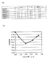
実施例4〜11のタイヤ:図7示すように、ショルダーブロックの踏み込み側の角部に面取りを形成したタイヤであり、Laを15mm、Lbを25mmに固定し、寸法Haを異ならせた。
【0151】
なお、各部の寸法、及び比率、及び評価は下記の図9に記載した通りである。
【0152】
試験の結果から、騒音レベルを十分に低下させるには、Haは0.2〜2.5mm、Ha/Cは0.02〜0.25とすることが良いことが分かる。
(試験例5)
従来例1の空気入りタイヤと、本発明の適用された実施例12〜19の空気入りタイヤとを用意し、試験例1と同様の試験を行った。
【0153】
試験例5では、試験例1と同様に図2に示すトレッドパターン(モノピッチ)を備えたタイヤにおいて試験を行った。
【0154】
実施例12〜19のタイヤ:図8に示すように、ショルダーブロックの蹴り出し側に面取りを形成したタイヤであり、Lcを12mm、Ldを6mm、Leを7mm、Lfを7mmに固定し、寸法Hbを異ならせた。
【0155】
なお、各部の寸法、及び比率、及び評価は図10に記載した通りである。
【0156】
試験の結果から、騒音レベルを十分に低下させるには、Hbは0.2〜2.5mm、Hb/Cは0.02〜0.25とすることが良いことが分かる。
(試験例6)
従来例1の空気入りタイヤと、本発明の適用された実施例20〜26の空気入りタイヤとを用意し、試験例1と同様の試験を行った。
【0157】
試験例6では、試験例1と同様に図2に示すトレッドパターン(モノピッチ)を備えたタイヤにおいて試験を行った。
【0158】
実施例20〜26のタイヤ:図7示すように、ショルダーブロックの踏み込み側の角部に面取りを形成したタイヤであり、Lbを25mm、Haを0.5mmに固定し、寸法Laを異ならせた。
【0159】
なお、各部の寸法、及び比率、及び評価は図11に記載した通りである。
【0160】
試験の結果から、騒音レベルを十分に低下させるには、Laは0.2〜2.5mm、La/Bは0.02〜0.25とすることが良いことが分かる。
(試験例7)
従来例1の空気入りタイヤと、本発明の適用された実施例27〜30の空気入りタイヤとを用意し、試験例1と同様の試験を行った。
【0161】
試験例7では、試験例1と同様に図2に示すトレッドパターン(モノピッチ)を備えたタイヤにおいて試験を行った。
【0162】
実施例27〜30のタイヤ:図7示すように、ショルダーブロックの踏み込み側の角部に面取りを形成したタイヤであり、Laを15mm、Haを0.5mmに固定し、寸法Lbを異ならせた。
【0163】
なお、各部の寸法、及び比率、及び評価は図12に記載した通りである。
【0164】
試験の結果から、騒音レベルを十分に低下させるには、Lbは10mm以上、Lb/Aは0.3以上とすることが良いことが分かる。
(試験例8)
従来例1の空気入りタイヤと、本発明の適用された実施例31〜35の空気入りタイヤとを用意し、試験例1と同様の試験を行った。
【0165】
試験例8では、試験例1と同様に図2に示すトレッドパターン(モノピッチ)を備えたタイヤにおいて試験を行った。
【0166】
実施例31〜35のタイヤ:図7示すように、ショルダーブロックの踏み込み側の角部に面取りを形成したタイヤであり、Ldを6mm、Leを7mm、Lfを7mm、Hbを0.5mmに固定し、寸法Lcを異ならせた。
【0167】
なお、各部の寸法、及び比率、及び評価は図13に記載した通りである。
【0168】
試験の結果から、騒音レベルを十分に低下させるには、Lcは5mm以上25mm以下、Lc/Aは0.17以上0.83以下とすることが良いことが分かる。
(試験例9)
従来例1の空気入りタイヤと、本発明の適用された実施例31〜35の空気入りタイヤとを用意し、試験例1と同様の試験を行った。
【0169】
試験例9では、試験例1と同様に図2に示すトレッドパターン(モノピッチ)を備えたタイヤにおいて試験を行った。
【0170】
実施例36〜40のタイヤ:図8示すように、ショルダーブロックの蹴り出し側に面取りを形成したタイヤであり、Lcを12mm、Leを7mm、Lfを7mm、Hbを0.5mmに固定し、寸法Ldを異ならせた。
【0171】
なお、各部の寸法、及び比率、及び評価は図14に記載した通りである。
【0172】
試験の結果から、騒音レベルを十分に低下させるには、Ldは3mm以上15mm以下、Ld/Bは0.15以上0.75以下とすることが良いことが分かる。
(試験例10)
従来例1の空気入りタイヤと、本発明の適用された実施例41〜45の空気入りタイヤとを用意し、試験例1と同様の試験を行った。
【0173】
試験例10では、試験例1と同様に図2に示すトレッドパターン(モノピッチ)を備えたタイヤにおいて試験を行った。
【0174】
実施例41〜45のタイヤ:図8に示すように、ショルダーブロックの蹴り出し側に面取りを形成したタイヤであり、Ldを6mm、Lcを12mm、Lfを7mm、Hbを0.5mmに固定し、寸法Leを異ならせた。
【0175】
なお、各部の寸法、及び比率、及び評価は図15に記載した通りである。
【0176】
試験の結果から、騒音レベルを十分に低下させるには、Leは2mm以上15mm以下、Le/Bは0.10以上0.75以下とすることが良いことが分かる。
(試験例11)
従来例1の空気入りタイヤと、本発明の適用された実施例46〜50の空気入りタイヤとを用意し、試験例1と同様の試験を行った。
【0177】
試験例10では、試験例1と同様に図2に示すトレッドパターン(モノピッチ)を備えたタイヤにおいて試験を行った。
【0178】
実施例46〜50のタイヤ:図8示すように、ショルダーブロックの蹴り出し側に面取りを形成したタイヤであり、Ldを6mm、Lcを12mm、Leを7mm、Hbを0.5mmに固定し、寸法Lfを異ならせた。
【0179】
なお、各部の寸法、及び比率、及び評価は図16に記載した通りである。
【0180】
試験の結果から、騒音レベルを十分に低下させるには、Lfは2mm以上、Lf/Bは0.10以上とすることが良いことが分かる。
(試験例12)
従来例2の空気入りタイヤと、本発明の適用された実施例51の空気入りタイヤとを用意し、試験例1と同様の試験を行った。
【0181】
試験例12では、図17(A)示すようなトレッドパターンを備えたタイヤにおいて試験例1,2と同様の試験を行った。
【0182】
試験タイヤのサイズは、195/65R15である。
【0183】
ブロック18のサイズは、寸法Aが30mm、寸法Bが25mm、高さが10mmである。なお、ショルダーブロック18cについては、接地領域の幅が寸法B(25mm)に相当する。
【0184】
ラグ溝16はタイヤ幅方向に対して40°で傾斜している。
【0185】
また、タイヤ赤道面CL上のリブ19は、幅Dが13mmである。
【0186】
従来例2のタイヤ:ショルダーブロック18cの踏面が平坦(タイヤ外輪郭形状に沿う)で、ショルダーブロック18cに面取りが形成されていなタイヤである。
【0187】
実施例51のタイヤ:図17(B)に示すように、ショルダーブロック18cのタイヤ赤道面側の端縁18Dの蹴り出し側の角部に第1の面取り24を、踏み込み縁に第2の面取り28を形成したタイヤである。
【0188】
なお、各部の寸法、及び比率は下記の表7に記載した通りである。
【0189】
【表7】
【0190】
【表8】
【発明の効果】
以上説明したように本発明の空気入りタイヤは上記の構成としたので、ブロック基調のトレッドパターンにおいて、タイヤ幅方向最外側のブロックを発生源とする騒音を確実に低減できる、という優れた効果を有する。
【図面の簡単な説明】
【図1】 本発明の一実施形態に係る空気入りタイヤのショルダーブロックの斜視図である。
【図2】 本発明の一実施形態に係る空気入りタイヤのトレッドの平面図である。
【図3】 ショルダーブロックのタイヤ幅方向に沿った断面図である。
【図4】 ショルダーブロックのタイヤ周方向に沿った断面図である。
【図5】 本発明の他の実施形態に係る空気入りタイヤのショルダーブロックの斜視図である。
【図6】 本発明の更に他の実施形態に係る空気入りタイヤのショルダーブロックの斜視図である。
【図7】 本発明の更に他の実施形態に係る空気入りタイヤのショルダーブロックの斜視図である。
【図8】 本発明の更に他の実施形態に係る空気入りタイヤのショルダーブロックの斜視図である。
【図9】 (A)及び(B)は、試験例4の結果である。
【図10】 (A)及び(B)は、試験例5の結果である。
【図11】 (A)及び(B)は、試験例6の結果である。
【図12】 (A)及び(B)は、試験例7の結果である。
【図13】 (A)及び(B)は、試験例8の結果である。
【図14】 (A)及び(B)は、試験例9の結果である。
【図15】 (A)及び(B)は、試験例10の結果である。
【図16】 (A)及び(B)は、試験例11の結果である。
【図17】 (A)は試験例12の空気入りタイヤのトレッドの平面図であり、(B)は実施例51のタイヤのショルダーブロックの平面図である。
【図18】 従来例に係る空気入りタイヤのショルダーブロックの斜視図である。
【図19】 本発明の更に他の実施形態に係る空気入りタイヤのトレッドの平面図である。
【図20】 図19に示すブロックの接地圧を示す説明図である。
【符号の説明】
10 空気入りタイヤ
12 トレッド
14 周方向溝
16 ラグ溝
18c ショルダーブロック(タイヤ幅方向最外側のブロック)
18A 踏み込み縁
18B 蹴り出し縁
18D タイヤ赤道面側の端縁
22 平坦部(高地部)
24 第1の面取り(第1の低地部)
28 第2の面取り(第2の低地部)[0001]
BACKGROUND OF THE INVENTION
The present invention relates to a pneumatic tire, and more particularly to a pneumatic tire that can achieve improvement in tire noise without impairing other performance.
[0002]
[Prior art]
A tire tread pattern exists for the purpose of considering driving in rainy weather, and most of them have grooves extending in the tire circumferential direction and the tire width direction, and therefore, a tread has a land portion called a block.
[0003]
However, it is known that pattern noise occurs due to the presence of this block.
[0004]
The prior art regarding this point can be roughly divided into two points.
[0005]
The first point is a method of setting a large angle with respect to the tire width direction of the lug groove for the purpose of extending the input applied by a single block in the time direction.
[0006]
The second point is a method that does not give a peak to a single frequency using the relationship with other blocks by giving a kind to the circumferential length of the block or by shifting the phase within the tire.
[0007]
These technologies have been developed mainly by a two-dimensional idea and have a long history.
[0008]
[Problems to be solved by the invention]
However, in recent automobiles that require a lot of quietness, the effect of the above prior art is not sufficient, and it is difficult to design with emphasis only on noise using the above method in consideration of other performance. Technology is required.
[0009]
In particular, in a single block, by setting the angle of the lug groove with respect to the tire width direction to be large (that is, changing the pattern design), for example, the block shape approaches a parallelogram elongated in the circumferential direction and the block rigidity is increased. It has been pointed out that there is a contradiction with uneven wear as well as a decrease.
[0010]
In view of the above facts, an object of the present invention is to provide a pneumatic tire that can improve noise without changing the basic design of the block pattern.
[0011]
[Means for Solving the Problems]
The invention according to
[0012]
Next, the operation of the pneumatic tire according to
[0013]
First, for a
[0014]
This
[0015]
Since the noise input is large at a part that fluctuates dynamically, this part is important for reducing noise.
[0016]
At this time, the edge (edge) 100A on the stepping side of the
[0017]
In the outermost block in the tire width direction according to
[0018]
For this reason, the block height gradually increases from the edge on the tire equatorial plane side toward the outer side in the tire width direction at the stepping-side edge or the kicking-out edge on the side where the first low ground portion is provided. Become.
[0019]
Therefore, when the first lowland portion is provided on the stepping side of the edge on the tire equatorial plane side, the stepping edge gradually comes into contact with the road surface when stepping on, and the force due to the stepping behavior Can be dispersed in the time direction, whereby the level of noise generated from the outermost block in the tire width direction can be kept low.
[0020]
In addition, when the first low ground portion is provided on the kicking side of the edge on the tire equatorial plane side, the kicking edge is gradually separated from the road surface at the time of kicking, and the kicking behavior is Can be dispersed in the time direction, whereby the level of noise generated from the outermost block in the tire width direction can be kept low.
[0021]
Moreover, in this outermost block in the tire width direction, all the ground contact edges on the outer side in the tire width direction are high ground portions along the tire outer contour, so that the difference in height of the ground contact portion at the stepping edge or the kicking edge is maximized. It can be turned on and the time for the end to contact (or leave) can be maximized.
Moreover, a noise level can fully be reduced by Ha / C being 0.02 or more and 0.25 or less.
[0022]
Here, the term “ground contact end” means that a pneumatic tire is mounted on a standard rim prescribed in JATMA YEAR BOOK (Japan Automobile Tire Association Standard 2001 version) and is the maximum size and ply rating applicable to JATMA YEAR BOOK. When the maximum load capacity is loaded with an internal pressure of 100% of the air pressure (maximum air pressure) corresponding to the load capacity (bold load in the internal pressure-load capacity correspondence table).
[0023]
When the TRA standard or ETRTO standard is applied at the place of use or manufacturing, the respective standards are followed.
[0024]
The invention according to
[0025]
Next, the operation of the pneumatic tire according to
[0026]
According to the pneumatic tire of
Moreover, a noise level can fully be reduced by Ld / B being 0.15 or more and 0.75 or less.
[0027]
The invention according to
[0028]
Next, the operation of the pneumatic tire according to
[0029]
The pneumatic tire according to
Moreover, a noise level can fully be reduced by Ha / C being 0.02 or more and 0.25 or less.
[0030]
According to a fourth aspect of the present invention, in the pneumatic tire according to the first or third aspect, at the edge of the tire equatorial plane side of the outermost block in the tire width direction from the highest part of the high altitude part. It is characterized in that Ha is 0.2 mm or more and 2.5 mm or less, where Ha is the dropping dimension in the block height direction to the lowest part of the first low-ground part.
[0031]
Next, the operation of the pneumatic tire according to
[0032]
By setting Ha to be 0.2 mm or more and 2.5 mm or less, the noise level can be sufficiently reduced.
[0033]
[0034]
[0035]
[0036]
Claim 5In the pneumatic tire according to
[0037]
next,Claim 5The operation of the pneumatic tire described in 1 will be described.
[0038]
By setting Hb to 0.2 mm or more and 2.5 mm or less, the noise level can be sufficiently reduced.
[0039]
Claim 6The invention described in
[0040]
next,Claim 6The operation of the pneumatic tire described in 1 will be described.
[0041]
By setting Hb / C to 0.02 or more and 0.25 or less, the noise level can be sufficiently reduced.
[0042]
Claim 7The invention described
[0043]
next,Claim 7The operation of the pneumatic tire described in 1 will be described.
[0044]
By setting La to 5 mm or more, the noise level can be sufficiently reduced.
[0045]
Claim 8The invention described
[0046]
next,Claim 8The operation of the pneumatic tire described in 1 will be described.
[0047]
By setting La / B to be 0.25 or more, the noise level can be sufficiently reduced.
[0048]
Claim 9The invention described
[0049]
next,Claim 9The operation of the pneumatic tire described in 1 will be described.
[0050]
By setting Lb to 10 mm or more, the noise level can be sufficiently reduced.
[0051]
Claim 10The invention described
[0052]
next,Claim 10The operation of the pneumatic tire described in 1 will be described.
[0053]
By setting Lb / A to 0.3 or more, the noise level can be sufficiently reduced.
[0054]
Claim 11The invention described
[0055]
next,Claim 11The operation of the pneumatic tire described in 1 will be described.
[0056]
By setting Lc to 2 mm or more and 25 mm or less, the noise level can be sufficiently reduced.
[0057]
Claim 12The invention described
[0058]
next,Claim 12The operation of the pneumatic tire described in 1 will be described.
[0059]
By setting Lc / A to 0.17 or more and 0.83 or less, the noise level can be sufficiently reduced.
[0060]
Claim 13The invention described
[0061]
next,Claim 13The operation of the pneumatic tire described in 1 will be described.
[0062]
By setting Ld to 3 mm or more and 15 mm or less, the noise level can be sufficiently reduced.
[0063]
[0064]
[0065]
[0066]
Claim 14The invention described
[0067]
next,Claim 14The operation of the pneumatic tire described in 1 will be described.
[0068]
By setting Le to 2 mm or more and 15 mm or less, the noise level can be sufficiently reduced.
[0069]
Claim 15The invention described
[0070]
next,Claim 15The operation of the pneumatic tire described in 1 will be described.
[0071]
By setting Le / B to be not less than 0.1 and not more than 0.75, the noise level can be sufficiently reduced.
[0072]
Claim 16In the pneumatic tire according to any one of
[0073]
next,Claim 16The operation of the pneumatic tire described in 1 will be described.
[0074]
By setting Lf to 2 mm or more, the noise level can be sufficiently reduced.
[0075]
Claim 17The invention described
[0076]
next,Claim 17The operation of the pneumatic tire described in 1 will be described.
[0077]
By setting Lf / B to be 0.1 or more, the noise level can be sufficiently reduced.
[0078]
Claim 18The invention described inClaims 1-17In the pneumatic tire according to any one of the above, when the outermost block in the tire width direction is viewed in a cross section along the tire width direction, any portion in the tire circumferential direction may have a high altitude portion. And lowland area.
[0079]
next,Claim 18The operation of the pneumatic tire described in 1 will be described.
[0080]
When the outermost block in the tire width direction is viewed in a cross section along the tire width direction, the tread shape is set so that the high ground portion and the low ground portion exist in any cross section of the tire circumferential direction. From the start of stepping to the end of kicking out, the peak of force can be dispersed continuously, whereby the level of noise generated from the outermost block in the tire width direction can be further reduced.
[0081]
Claim 19The invention described inClaims 1-18In the pneumatic tire according to any one of the above, in the outermost block in the tire width direction, the high altitude portion has a flat portion that matches the outer contour shape of the tire.
[0082]
next,Claim 19The operation of the pneumatic tire described in 1 will be described.
[0083]
Making the tread surface of the block three-dimensional changes the ground contact characteristic greatly and changes the block characteristic. If the tread surface is too three-dimensional, that is, if there is no flat portion on the tread surface that matches the outer contour of the tire, the noise level cannot be reduced.
[0084]
DETAILED DESCRIPTION OF THE INVENTION
[First Embodiment]
Hereinafter, a first embodiment of the present invention will be described in detail with reference to the drawings.
[0085]
As shown in FIG. 2, the
[0086]
The
[0087]
As shown in FIG. 1, the tread surface of the
[0088]
Here, in FIG. 1,
[0089]
A
[0090]
As shown in FIG. 3, the
[0091]
As shown in FIG. 1, a
[0092]
That is, the tire equatorial plane side edge 18Aa of the stepping
[0093]
Next, a
[0094]
As shown in FIG. 4, the
[0095]
As shown in FIG. 1, the
[0096]
Reference symbol A is a dimension measured along the tire circumferential direction of the
[0097]
Next, the preferable range of each dimension and ratio is demonstrated.
[0098]
The dimension Ha is preferably 0.2 mm or more and 2.5 mm or less.
[0099]
The ratio Ha / C is preferably 0.02 or more and 0.25 or less.
[0100]
The dimension Hb is preferably 0.2 mm or greater and 2.5 mm or less.
[0101]
The ratio Hb / C is preferably 0.02 or more and 0.25 or less.
[0102]
The dimension La is preferably 5 mm or more.
[0103]
The ratio La / B is preferably 0.25 or more.
[0104]
The dimension Lb is preferably 10 mm or more.
[0105]
The ratio Lb / A is preferably 0.3 or more.
[0106]
The dimension Lc is preferably 2 mm or more and 25 mm or less.
[0107]
The ratio Lc / A is preferably 0.17 or more and 0.83 or less.
[0108]
The dimension Ld is preferably 3 mm or more and 15 mm or less.
[0109]
The ratio Ld / B is preferably 0.15 or more and 0.75 or less.
[0110]
The dimension Le is preferably 2 mm or more and 15 mm or less.
[0111]
The ratio Le / B is preferably 0.1 or more and 0.75 or less.
[0112]
The dimension Lf is preferably 2 mm or more.
[0113]
The ratio Lf / B is preferably 0.1 or more.
(Function)
Next, the effect | action of the
[0114]
When the
[0115]
In addition, since the height of the
[0116]
That is, the
[0117]
Moreover, since the tire width direction dimension of the
[0118]
Further, since the
[0119]
Here, dimension Ha, ratio Ha / C, dimension Hb, ratio Hb / C, dimension La, ratio La / B, dimension Lb, ratio Lb / A, dimension Lc, ratio Lc / A, dimension Ld, ratio Ld / B If the dimension Le, the ratio Le / B, the dimension Lf, and the ratio Lf / B are out of the above-described ranges, the generation of noise cannot be sufficiently suppressed.
[0120]
In FIG. 1, the
[0121]
Further, when the
[0122]
Thereby, the peak of force can be continuously distributed from the start of stepping to the end of kicking out, whereby the level of noise generated from the
[0123]
Further, in the
[0124]
Also in the
[0125]
Thereby, also in the
[Other Embodiments]
In the above embodiment, the
[0126]
Moreover, in the said embodiment, although the
[0127]
Moreover, in the
[0128]
In the pattern shown in FIG. 19, the
[0129]
FIG. 20 shows the contact pressure of the pattern of FIG. 19, where the portion with a high density on the tread has a high contact pressure and the portion with a low concentration shows a low contact pressure.
(Test Example 1)
The pneumatic tire of Conventional Example 1 and the pneumatic tire of Example 1 to which the present invention was applied were prepared, and noise was measured using an indoor drum tester.
[0130]
In the test, the sound pressure (peak of the sound pressure waveform) in the vicinity of the test tire at a speed of 80 km / h was measured.
[0131]
In Test Example 1, a test was performed on a tire having a tread pattern (mono pitch) shown in FIG.
[0132]
The size of the test tire is 195 / 65R15, and the block size is 30 mm for dimension A, 20 mm for dimension B, and 10 mm for dimension C (see FIG. 1).
[0133]
For the shoulder block, the width of the ground contact area corresponds to the dimension B (20 mm).
[0134]
Tire of Conventional Example 1: A tire having a flat tread surface (following the outer contour of the tire) and no chamfering (see FIG. 18).
[0135]
Tire of Example 1: As shown in FIG. 7, the tire is a tire in which chamfers are formed at the corners on the stepping side of the shoulder block. In addition, the dimension and ratio of each part are as having described in Table 1 below.
[0136]
[Table 1]
[0137]
The evaluation is an index display in which the peak size of the sound pressure waveform of the pneumatic tire of Conventional Example 1 is set to 100, and the smaller the value, the lower the noise level and the lower the amount of noise generated. ing. The test results are as shown in Table 2 below, and it can be seen that the tire of Example 1 has a sufficiently low noise level.
[0138]
[Table 2]
The pneumatic tire of Conventional Example 1 and the pneumatic tire of Example 2 to which the present invention was applied were prepared, and the same test as in Test Example 1 was performed.
[0139]
In Test Example 2, the test was performed on a tire having the tread pattern (mono pitch) shown in FIG. 2 as in Test Example 1, but only the shape of the shoulder block was different.
[0140]
Tire of Example 2: As shown in FIG. 8, the tire is a tire in which a chamfer is formed on the kicking edge of the shoulder block. In addition, the dimension and ratio of each part are as having described in Table 3 below.
[0141]
[Table 3]
[0142]
The test results are as described in Table 4 below, and it can be seen that the tire of Example 2 has a sufficiently low noise level.
[0143]
[Table 4]
The pneumatic tire of Conventional Example 1 and the pneumatic tire of Example 3 to which the present invention was applied were prepared, and the same test as in Test Example 1 was performed.
[0144]
In Test Example 3, a test was performed on a tire having the tread pattern (mono pitch) shown in FIG. 2 as in Test Examples 1 and 2, but only the shape of the shoulder block was different.
[0145]
Tire of Example 3 As shown in FIG. 1, the tire is a tire in which chamfers are formed at the corner of the shoulder block on the stepping side and the kicking edge of the shoulder block. In addition, the dimension and ratio of each part are as having described in Table 5 below.
[0146]
[Table 5]
[0147]
The test results are as described in Table 6 below, and it can be seen that the noise level of the tire of Example 3 is lower than that of Examples 1 and 2 described above because two chamfers are provided.
[0148]
[Table 6]
The pneumatic tire of Conventional Example 1 and the pneumatic tires of Examples 4 to 11 to which the present invention was applied were prepared, and the same test as in Test Example 1 was performed.
[0149]
In Test Example 4, the test was performed on a tire having the tread pattern (mono pitch) shown in FIG.
[0150]
Tires of Examples 4 to 11: As shown in FIG. 7, tires having chamfered corners on the stepped side of the shoulder block, La was fixed to 15 mm, Lb was fixed to 25 mm, and dimension Ha was varied.
[0151]
In addition, the dimension of each part, a ratio, and evaluation are as having described in following FIG.
[0152]
From the test results, it can be seen that Ha is preferably 0.2 to 2.5 mm and Ha / C is 0.02 to 0.25 in order to sufficiently reduce the noise level.
(Test Example 5)
The pneumatic tire of Conventional Example 1 and the pneumatic tires of Examples 12 to 19 to which the present invention was applied were prepared, and the same test as in Test Example 1 was performed.
[0153]
In Test Example 5, the test was performed on a tire having the tread pattern (mono pitch) shown in FIG.
[0154]
Tires of Examples 12 to 19: As shown in FIG. 8, tires in which chamfers are formed on the shoulder block kick side, Lc is 12 mm, Ld is 6 mm, Le is 7 mm, and Lf is 7 mm. Different Hb.
[0155]
In addition, the dimension of each part, a ratio, and evaluation are as having described in FIG.
[0156]
From the test results, it can be seen that Hb is preferably 0.2 to 2.5 mm and Hb / C is 0.02 to 0.25 in order to sufficiently reduce the noise level.
(Test Example 6)
The pneumatic tire of Conventional Example 1 and the pneumatic tires of Examples 20 to 26 to which the present invention was applied were prepared, and the same test as in Test Example 1 was performed.
[0157]
In Test Example 6, the test was performed on a tire provided with the tread pattern (mono pitch) shown in FIG.
[0158]
Tires of Examples 20 to 26: As shown in FIG. 7, tires having chamfered corners on the stepping side of the shoulder block, Lb was fixed to 25 mm, Ha was fixed to 0.5 mm, and dimension La was varied. .
[0159]
In addition, the dimension of each part, a ratio, and evaluation are as having described in FIG.
[0160]
From the test results, it is understood that La is preferably 0.2 to 2.5 mm and La / B is 0.02 to 0.25 in order to sufficiently reduce the noise level.
(Test Example 7)
The pneumatic tire of Conventional Example 1 and the pneumatic tires of Examples 27 to 30 to which the present invention was applied were prepared, and the same test as in Test Example 1 was performed.
[0161]
In Test Example 7, the test was performed on a tire having the tread pattern (mono pitch) shown in FIG.
[0162]
Tires of Examples 27 to 30: As shown in FIG. 7, tires having chamfered corners on the stepped side of the shoulder block, La fixed at 15 mm, Ha fixed at 0.5 mm, and dimension Lb varied. .
[0163]
In addition, the dimension of each part, a ratio, and evaluation are as having described in FIG.
[0164]
From the test results, it can be seen that Lb is preferably 10 mm or more and Lb / A is 0.3 or more in order to sufficiently reduce the noise level.
(Test Example 8)
The pneumatic tire of Conventional Example 1 and the pneumatic tires of Examples 31 to 35 to which the present invention was applied were prepared, and the same test as in Test Example 1 was performed.
[0165]
In Test Example 8, a test was performed on a tire having the tread pattern (mono pitch) shown in FIG.
[0166]
Tires of Examples 31 to 35: As shown in FIG. 7, tires having chamfered corners on the stepped side of the shoulder block, Ld being 6 mm, Le being 7 mm, Lf being 7 mm, and Hb being 0.5 mm However, the dimension Lc was varied.
[0167]
In addition, the dimension of each part, a ratio, and evaluation are as having described in FIG.
[0168]
From the test results, it can be seen that Lc is preferably 5 mm or more and 25 mm or less, and Lc / A is 0.17 or more and 0.83 or less in order to sufficiently reduce the noise level.
(Test Example 9)
The pneumatic tire of Conventional Example 1 and the pneumatic tires of Examples 31 to 35 to which the present invention was applied were prepared, and the same test as in Test Example 1 was performed.
[0169]
In Test Example 9, the test was performed on a tire having the tread pattern (mono pitch) shown in FIG.
[0170]
Tires of Examples 36 to 40: As shown in FIG. 8, tires having a chamfer formed on the shoulder block kick side, Lc is fixed to 12 mm, Le is 7 mm, Lf is 7 mm, and Hb is fixed to 0.5 mm. The dimension Ld was varied.
[0171]
In addition, the dimension of each part, a ratio, and evaluation are as having described in FIG.
[0172]
From the test results, it can be seen that Ld is preferably 3 mm or more and 15 mm or less and Ld / B is 0.15 or more and 0.75 or less in order to sufficiently reduce the noise level.
(Test Example 10)
The pneumatic tire of Conventional Example 1 and the pneumatic tires of Examples 41 to 45 to which the present invention was applied were prepared, and the same test as in Test Example 1 was performed.
[0173]
In Test Example 10, the test was performed on a tire provided with the tread pattern (mono pitch) shown in FIG.
[0174]
Tires of Examples 41 to 45: As shown in FIG. 8, this is a tire in which a chamfer is formed on the kicking side of the shoulder block, and Ld is 6 mm, Lc is 12 mm, Lf is 7 mm, and Hb is 0.5 mm. , The dimension Le was varied.
[0175]
In addition, the dimension of each part, a ratio, and evaluation are as having described in FIG.
[0176]
From the test results, it is found that Le is preferably 2 mm or more and 15 mm or less, and Le / B is 0.10 or more and 0.75 or less in order to sufficiently reduce the noise level.
(Test Example 11)
The pneumatic tire of Conventional Example 1 and the pneumatic tires of Examples 46 to 50 to which the present invention was applied were prepared, and the same test as in Test Example 1 was performed.
[0177]
In Test Example 10, the test was performed on a tire provided with the tread pattern (mono pitch) shown in FIG.
[0178]
Tires of Examples 46 to 50: As shown in FIG. 8, tires having chamfers formed on the shoulder block kick side, Ld is 6 mm, Lc is 12 mm, Le is 7 mm, and Hb is fixed to 0.5 mm. The dimension Lf was varied.
[0179]
In addition, the dimension of each part, a ratio, and evaluation are as having described in FIG.
[0180]
From the test results, it can be seen that Lf should be 2 mm or more and Lf / B should be 0.10 or more in order to sufficiently reduce the noise level.
(Test Example 12)
The pneumatic tire of Conventional Example 2 and the pneumatic tire of Example 51 to which the present invention was applied were prepared, and the same test as in Test Example 1 was performed.
[0181]
In Test Example 12, a test similar to Test Examples 1 and 2 was performed on a tire having a tread pattern as shown in FIG.
[0182]
The size of the test tire is 195 / 65R15.
[0183]
The
[0184]
The
[0185]
Further, the rib 19 on the tire equatorial plane CL has a width D of 13 mm.
[0186]
Tire of Conventional Example 2: A tire in which the tread of the
[0187]
Tire of Example 51: As shown in FIG. 17 (B), a
[0188]
In addition, the dimension and ratio of each part are as having described in Table 7 below.
[0189]
[Table 7]
[0190]
[Table 8]
【The invention's effect】
As described above, since the pneumatic tire of the present invention has the above-described configuration, the block-based tread pattern has an excellent effect of reliably reducing noise generated from the outermost block in the tire width direction. Have.
[Brief description of the drawings]
FIG. 1 is a perspective view of a shoulder block of a pneumatic tire according to an embodiment of the present invention.
FIG. 2 is a plan view of a tread of a pneumatic tire according to an embodiment of the present invention.
FIG. 3 is a cross-sectional view of the shoulder block along the tire width direction.
FIG. 4 is a cross-sectional view of the shoulder block along the tire circumferential direction.
FIG. 5 is a perspective view of a shoulder block of a pneumatic tire according to another embodiment of the present invention.
FIG. 6 is a perspective view of a shoulder block of a pneumatic tire according to still another embodiment of the present invention.
FIG. 7 is a perspective view of a shoulder block of a pneumatic tire according to still another embodiment of the present invention.
FIG. 8 is a perspective view of a shoulder block of a pneumatic tire according to still another embodiment of the present invention.
9A and 9B are the results of Test Example 4. FIG.
10A and 10B are the results of Test Example 5. FIG.
11A and 11B are the results of Test Example 6. FIG.
12A and 12B are the results of Test Example 7. FIG.
13 (A) and (B) are the results of Test Example 8. FIG.
14A and 14B are the results of Test Example 9. FIG.
15 (A) and (B) are the results of Test Example 10. FIG.
16 (A) and (B) are the results of Test Example 11. FIG.
17A is a plan view of the tread of the pneumatic tire of Test Example 12, and FIG. 17B is a plan view of the shoulder block of the tire of Example 51. FIG.
FIG. 18 is a perspective view of a shoulder block of a pneumatic tire according to a conventional example.
FIG. 19 is a plan view of a tread of a pneumatic tire according to still another embodiment of the present invention.
20 is an explanatory diagram showing a ground pressure of the block shown in FIG. 19;
[Explanation of symbols]
10 Pneumatic tire
12 tread
14 Circumferential groove
16 lug groove
18c Shoulder block (outermost block in the tire width direction)
18A Stepping edge
18B kicking edge
18D tire equator edge
22 Flat part (high altitude part)
24 1st chamfer (1st lowland part)
28 Second chamfer (second lowland area)
Claims (19)
タイヤ幅方向最外側のブロックのタイヤ赤道面側の端縁には、踏み込み側の端縁または蹴り出し側の端縁の何れか一方にタイヤ外輪郭に沿った高地部が設けられ、踏み込み側の端縁または蹴り出し側の端縁の何れか他方に前記高地部から離れるにしたがってブロック高さが徐々に低くなる第1の低地部が設けられており、
タイヤ幅方向最外側のブロックの接地端では、全てがタイヤ外輪郭に沿った高地部とされており、
前記タイヤ幅方向最外側のブロックのタイヤ赤道面側の端縁における前記高地部の最も高い部分から前記第1の低地部の最も低い部分までのブロック高さ方向の落し寸法をHa、
前記タイヤ幅方向最外側のブロックのタイヤ赤道面側の端縁におけるブロック高さをCとしたときに、
Ha/Cが0.02以上0.25以下である、ことを特徴とする空気入りタイヤ。A pneumatic tire comprising a tread having a plurality of blocks defined by a plurality of circumferential grooves extending along the tire circumferential direction and a plurality of grooves intersecting the circumferential groove,
The edge on the tire equatorial plane side of the outermost block in the tire width direction is provided with a high altitude portion along the outer contour of the tire on either the stepping side edge or the kicking side edge. A first low ground portion where the block height gradually decreases as the distance from the high ground portion is provided on either the end edge or the edge on the kick-out side,
At the ground contact edge of the outermost block in the tire width direction, everything is considered to be a high altitude part along the tire outer contour ,
The drop dimension in the block height direction from the highest part of the high ground part to the lowest part of the first low ground part at the edge of the tire equatorial plane side of the outermost block in the tire width direction is Ha,
When the block height at the edge on the tire equatorial plane side of the outermost block in the tire width direction is C,
A pneumatic tire characterized in that Ha / C is 0.02 or more and 0.25 or less .
タイヤ幅方向最外側のブロックの踏み込み側縁または蹴り出し側縁では、タイヤ外輪郭に沿った高地部と、前記高地部よりも低く前記高地部から離れるにしたがってブロック高さが徐々に低くなる第2の低地部とが設けられており、
前記第2の低地部が設けられている前記タイヤ幅方向最外側のブロックの踏み込み側縁または蹴り出し側縁において、タイヤ赤道面側の端部から前記第2の低地部までのタイヤ幅方向に沿って計測した寸法をLd、前記タイヤ幅方向最外側のブロックの、タイヤ赤道面側の端縁から接地端までのタイヤ幅方向に沿って計測した寸法をBとしたときに、Ld/Bが0.15以上0.75以下である、ことを特徴とする空気入りタイヤ。A pneumatic tire having a tread having a plurality of blocks defined by a plurality of grooves intersecting each other,
At the stepping side edge or the kicking side edge of the outermost block in the tire width direction, the height of the block is gradually lowered as the distance from the high ground portion is lower than the high ground portion and lower than the high ground portion. 2 lowland areas ,
In the step width side edge or the kick side edge of the outermost block in the tire width direction where the second low ground portion is provided, in the tire width direction from the end portion on the tire equatorial plane side to the second low ground portion Ld / B is the dimension measured along the tire width direction from the edge on the tire equatorial plane side to the ground contact edge of the outermost block in the tire width direction, where Ld is the dimension measured along the tire width direction. A pneumatic tire characterized by being 0.15 or more and 0.75 or less .
タイヤ幅方向最外側のブロックのタイヤ赤道面側の端縁には、踏み込み側の端縁または蹴り出し側の端縁の何れか一方にタイヤ外輪郭に沿った高地部が設けられ、踏み込み側の端縁または蹴り出し側の端縁の何れか他方に前記高地部から離れるにしたがってブロック高さが徐々に低くなる第1の低地部が設けられており、
タイヤ幅方向最外側のブロックの前記第1の低地部が設けられていない方の踏み込み側縁または蹴り出し側縁では、タイヤ外輪郭に沿った高地部と、前記高地部よりも低く前記高地部から離れるにしたがってブロック高さが徐々に低くなる第2の低地部とが設けられており、
前記タイヤ幅方向最外側のブロックのタイヤ赤道面側の端縁における前記高地部の最も高い部分から前記第1の低地部の最も低い部分までのブロック高さ方向の落し寸法をHa、前記タイヤ幅方向最外側のブロックのタイヤ赤道面側の端縁におけるブロック高さをCとしたときに、Ha/Cが0.02以上0.25以下である、ことを特徴とする空気入りタイヤ。A pneumatic tire having a tread having a plurality of blocks defined by a plurality of grooves intersecting each other,
The edge on the tire equatorial plane side of the outermost block in the tire width direction is provided with a high altitude portion along the outer contour of the tire on either the stepping side edge or the kicking side edge. A first low ground portion where the block height gradually decreases as the distance from the high ground portion is provided on either the end edge or the edge on the kick-out side,
The stepped side edge or the kicking side edge of the outermost block in the tire width direction where the first low ground part is not provided has a high ground part along a tire outer contour, and the high ground part lower than the high ground part And a second lowland portion where the block height gradually decreases as the distance from the
A drop dimension in the block height direction from the highest part of the high altitude part to the lowest part of the first low ground part at the edge on the tire equatorial plane side of the outermost block in the tire width direction is Ha, the tire width A pneumatic tire characterized in that Ha / C is 0.02 or more and 0.25 or less, where C is a block height at an edge on the tire equatorial plane side of the outermost block in the direction .
Hbが0.2mm以上2.5mm以下である、ことを特徴とする請求項2また3に記載の空気入りタイヤ。In the step-in side edge or the kick-out side edge provided with the second lowland part, a drop dimension in the block height direction from the highest part of the highland part to the lowest part of the second lowland part is set. When Hb
The pneumatic tire according to claim 2 or 3, wherein Hb is not less than 0.2 mm and not more than 2.5 mm.
前記タイヤ幅方向最外側のブロックのタイヤ赤道面側の端縁におけるブロック高さをCとしたときに、
Hb/Cが0.02以上0.25以下である、ことを特徴とする請求項2、3、5の何れか1項に記載の空気入りタイヤ。In the step-in side edge or the kick-out side edge provided with the second lowland part, a drop dimension in the block height direction from the highest part of the highland part to the lowest part of the second lowland part is set. Hb,
When the block height at the edge on the tire equatorial plane side of the outermost block in the tire width direction is C,
The pneumatic tire according to any one of claims 2, 3, and 5 , wherein Hb / C is 0.02 or more and 0.25 or less.
寸法Laが5mm以上である、ことを特徴とする請求項1、3、4の何れか1項に記載の空気入りタイヤ。When the dimension when measured from the edge on the tire equatorial plane side to the tire width direction outer side of the first lowland part is La,
The pneumatic tire according to any one of claims 1, 3 , and 4 , wherein the dimension La is 5 mm or more.
前記タイヤ幅方向最外側のブロックの、タイヤ赤道面側の端縁からタイヤ幅方向外側へ計測した接地端までの寸法をBとしたときに、
La/Bが0.25以上である、ことを特徴とする請求項1、3、4、7の何れか1項に記載の空気入りタイヤ。The dimension of the first lowland portion measured from the edge on the tire equatorial plane side to the outer side in the tire width direction is La,
When the dimension of the outermost block in the tire width direction from the edge on the tire equatorial plane side to the ground contact edge measured outward in the tire width direction is B,
The pneumatic tire according to any one of claims 1, 3 , 4 , and 7 , wherein La / B is 0.25 or more.
Lbが10mm以上である、ことを特徴とする請求項1、3、4、7、8の何れか1項に記載の空気入りタイヤ。When the dimension measured along the tire circumferential direction from the stepping side edge or the kicking side edge provided with the first lowland part of the first lowland part is Lb,
The pneumatic tire according to any one of claims 1, 3, 4, 7 , and 8 , wherein Lb is 10 mm or more.
前記タイヤ赤道面側の端縁の、タイヤ周方向に沿って計測した寸法をAとしたときに、
Lb/Aが0.3以上である、ことを特徴とする請求項1、3、4、7、8、9の何れか1項に記載の空気入りタイヤ。The dimension measured along the tire circumferential direction from the stepping side edge or the kicking side edge provided with the first lowland part of the first lowland part is Lb,
When the dimension measured along the tire circumferential direction of the edge on the tire equatorial plane side is A,
Lb / A is 0.3 or more, The pneumatic tire of any one of Claim 1, 3, 4, 7 , 8 , 9 characterized by the above-mentioned.
前記タイヤ周方向最外端P1から前記第2の低地部が設けられている踏み込み側縁または蹴り出し側縁までのタイヤ周方向に沿って計測した寸法をLcとしたときに、
Lcが2mm以上25mm以下であることを特徴とする請求項2、3、5、6の何れか1項に記載の空気入りタイヤ。P1 is the outermost end in the tire circumferential direction farthest in the tire circumferential direction of the second lowland part from the stepping side edge or the kicking side edge provided with the second lowland part,
When the dimension measured along the tire circumferential direction from the tire circumferential direction outermost end P1 to the stepping side edge or the kicking side edge where the second low ground portion is provided is Lc,
Lc is 2 mm or more and 25 mm or less, The pneumatic tire of any one of Claim 2, 3, 5 , 6 characterized by the above-mentioned.
前記タイヤ周方向最外端P1から前記第2の低地部が設けられている踏み込み側縁または蹴り出し側縁までのタイヤ周方向に沿って計測した寸法をLcとし、
前記タイヤ赤道面側の端縁の、タイヤ周方向に沿って計測した寸法をAとしたときに、
Lc/Aが0.17以上0.83以下であることを特徴とする請求項2、3、5、6、11の何れか1項に記載の空気入りタイヤ。P1 is the outermost end in the tire circumferential direction farthest in the tire circumferential direction of the second lowland part from the stepping side edge or the kicking side edge provided with the second lowland part,
Lc is a dimension measured along the tire circumferential direction from the tire circumferential direction outermost end P1 to the stepping side edge or the kicking side edge where the second low ground portion is provided,
When the dimension measured along the tire circumferential direction of the edge on the tire equatorial plane side is A,
The pneumatic tire according to any one of claims 2, 3, 5 , 6 , and 11 , wherein Lc / A is 0.17 or more and 0.83 or less.
Ldが3mm以上15mm以下である、ことを特徴とする請求項2、3、5、6、11、12の何れか1項に記載の空気入りタイヤ。In the step width side edge or the kick side edge of the outermost block in the tire width direction where the second low ground portion is provided, in the tire width direction from the end portion on the tire equatorial plane side to the second low ground portion When the dimension measured along the line is Ld,
Ld is 3 mm or more and 15 mm or less, The pneumatic tire of any one of Claim 2, 3, 5 , 6 , 11 , 12 characterized by the above-mentioned.
前記タイヤ周方向最外端P1を通るタイヤ周方向に沿った仮想直線FLと前記第2の低地部の設けられた踏み込み側縁または蹴り出し側縁との交点をP2とし、
前記交点P2から前記第2の低地部のタイヤ赤道面側の端部までのタイヤ幅方向に沿って計測した寸法をLeとしたときに、
Leが2mm以上15mm以下である、ことを特徴とする請求項2、3、5、6、11、12、13の何れか1項に記載の空気入りタイヤ。P1 is the outermost end in the tire circumferential direction farthest in the tire circumferential direction of the second lowland part from the stepping side edge or the kicking side edge provided with the second lowland part,
An intersection point of a virtual straight line FL along the tire circumferential direction passing through the tire circumferential direction outermost end P1 and a stepping side edge or a kicking side edge provided with the second low ground portion is defined as P2,
When the dimension measured along the tire width direction from the intersection point P2 to the end of the second lowland portion on the tire equatorial plane side is Le,
The pneumatic tire according to any one of claims 2, 3, 5 , 6 , 11 , 12 , and 13, wherein Le is 2 mm or more and 15 mm or less.
前記タイヤ周方向最外端P1を通るタイヤ周方向に沿った仮想直線FLと前記第2の低地部の設けられた踏み込み側縁または蹴り出し側縁との交点をP2とし、
前記交点P2から前記第2の低地部のタイヤ赤道面側の端部までのタイヤ幅方向に沿って計測した寸法をLe、
前記タイヤ幅方向最外側のブロックの、タイヤ赤道面側の端縁からタイヤ幅方向外側へ計測した接地端までの寸法をBとしたときに、
Le/Bが0.1以上0.75以下である、ことを特徴とする請求項2、3、5、6、11、12、13、14の何れか1項に記載の空気入りタイヤ。P1 is the outermost end in the tire circumferential direction farthest in the tire circumferential direction of the second lowland part from the stepping side edge or the kicking side edge provided with the second lowland part,
An intersection point of a virtual straight line FL along the tire circumferential direction passing through the tire circumferential direction outermost end P1 and a stepping side edge or a kicking side edge provided with the second low ground portion is defined as P2,
The dimension measured along the tire width direction from the intersection P2 to the end of the second lowland portion on the tire equatorial plane side is Le,
When the dimension of the outermost block in the tire width direction from the edge on the tire equatorial plane side to the ground contact edge measured outward in the tire width direction is B,
The pneumatic tire according to any one of claims 2, 3, 5 , 6 , 11 , 12 , 13, and 14, wherein Le / B is 0.1 or more and 0.75 or less.
前記タイヤ周方向最外端P1を通るタイヤ周方向に沿った仮想直線FLと前記第2の低地部の設けられた踏み込み側縁または蹴り出し側縁との交点をP2とし、
前記交点P2から前記第2の低地部のタイヤ幅方向外側端までのタイヤ幅方向に沿って計測した寸法をLfとしたときに、
Lfが2mm以上である、ことを特徴とする請求項2、3、5、6、11、12、13、14、15の何れか1項に記載の空気入りタイヤ。P1 is the outermost end in the tire circumferential direction farthest in the tire circumferential direction of the second lowland part from the stepping side edge or the kicking side edge provided with the second lowland part,
An intersection point of a virtual straight line FL along the tire circumferential direction passing through the tire circumferential direction outermost end P1 and a stepping side edge or a kicking side edge provided with the second low ground portion is defined as P2,
When the dimension measured along the tire width direction from the intersection point P2 to the outer end in the tire width direction of the second low ground part is Lf,
The pneumatic tire according to any one of claims 2, 3, 5 , 6 , 11 , 12 , 13, 14, and 15, wherein Lf is 2 mm or more.
前記タイヤ周方向最外端P1を通るタイヤ周方向に沿った仮想直線FLと前記第2の低地部の設けられた踏み込み側縁または蹴り出し側縁との交点をP2とし、
前記交点P2から前記第2の低地部のタイヤ幅方向外側端までのタイヤ幅方向に沿って計測した寸法をLf、
前記タイヤ幅方向最外側のブロックの、タイヤ赤道面側の端縁から接地端までのタイヤ幅方向に沿って計測した寸法をBとしたときに、
Lf/Bが0.1以上である、ことを特徴とする請求項2、3、5、6、11、12、13、14,15,16の何れか1項に記載の空気入りタイヤ。P1 is the outermost end in the tire circumferential direction farthest in the tire circumferential direction of the second lowland part from the stepping side edge or the kicking side edge provided with the second lowland part,
An intersection point of a virtual straight line FL along the tire circumferential direction passing through the tire circumferential direction outermost end P1 and a stepping side edge or a kicking side edge provided with the second low ground part is defined as P2,
The dimension measured along the tire width direction from the intersection point P2 to the outer end in the tire width direction of the second lowland portion is Lf,
When the dimension measured along the tire width direction from the edge on the tire equatorial plane side to the ground contact edge of the outermost block in the tire width direction is B,
Lf / B is 0.1 or more, The pneumatic tire of any one of Claim 2, 3, 5 , 6 , 11 , 12 , 13, 14, 15, 16 characterized by the above-mentioned.
Priority Applications (7)
| Application Number | Priority Date | Filing Date | Title |
|---|---|---|---|
| JP2001371236A JP4119644B2 (en) | 2001-12-05 | 2001-12-05 | Pneumatic tire |
| ES02780776T ES2297017T3 (en) | 2001-05-11 | 2002-05-10 | TIRE. |
| PCT/JP2002/004567 WO2002102611A1 (en) | 2001-05-11 | 2002-05-10 | Pneumatic tire |
| EP02780776A EP1386758B1 (en) | 2001-05-11 | 2002-05-10 | Pneumatic tire |
| US10/476,703 US7281554B2 (en) | 2001-05-11 | 2002-05-10 | Pneumatic tire with tread having blocks including highland portions and convex surface that is smoothly chamfered and defines line edge at the top of block sidewall |
| DE60224027T DE60224027T2 (en) | 2001-05-11 | 2002-05-10 | TIRE |
| CNB028015886A CN100441430C (en) | 2001-05-11 | 2002-05-10 | pneumatic tire |
Applications Claiming Priority (1)
| Application Number | Priority Date | Filing Date | Title |
|---|---|---|---|
| JP2001371236A JP4119644B2 (en) | 2001-12-05 | 2001-12-05 | Pneumatic tire |
Publications (2)
| Publication Number | Publication Date |
|---|---|
| JP2003170708A JP2003170708A (en) | 2003-06-17 |
| JP4119644B2 true JP4119644B2 (en) | 2008-07-16 |
Family
ID=19180312
Family Applications (1)
| Application Number | Title | Priority Date | Filing Date |
|---|---|---|---|
| JP2001371236A Expired - Lifetime JP4119644B2 (en) | 2001-05-11 | 2001-12-05 | Pneumatic tire |
Country Status (1)
| Country | Link |
|---|---|
| JP (1) | JP4119644B2 (en) |
Families Citing this family (7)
| Publication number | Priority date | Publication date | Assignee | Title |
|---|---|---|---|---|
| JP4717548B2 (en) * | 2005-08-23 | 2011-07-06 | 株式会社ブリヂストン | Pneumatic tire |
| JP2007062650A (en) * | 2005-09-01 | 2007-03-15 | Bridgestone Corp | Pneumatic tire |
| JP2009023601A (en) * | 2007-07-23 | 2009-02-05 | Sumitomo Rubber Ind Ltd | Pneumatic tire |
| JP5707923B2 (en) * | 2010-12-17 | 2015-04-30 | 横浜ゴム株式会社 | Pneumatic tire |
| JP6012442B2 (en) * | 2012-11-30 | 2016-10-25 | 株式会社ブリヂストン | Pneumatic tire |
| WO2014083758A1 (en) | 2012-11-30 | 2014-06-05 | 株式会社ブリヂストン | Pneumatic tire |
| JP7056150B2 (en) * | 2017-12-28 | 2022-04-19 | 住友ゴム工業株式会社 | tire |
-
2001
- 2001-12-05 JP JP2001371236A patent/JP4119644B2/en not_active Expired - Lifetime
Also Published As
| Publication number | Publication date |
|---|---|
| JP2003170708A (en) | 2003-06-17 |
Similar Documents
| Publication | Publication Date | Title |
|---|---|---|
| JP5181927B2 (en) | Pneumatic tire | |
| WO2002102611A1 (en) | Pneumatic tire | |
| JP6762267B2 (en) | tire | |
| CN106414112A (en) | pneumatic tire | |
| JP6304329B2 (en) | Pneumatic tire | |
| JPH09109613A (en) | Pneumatic radial tire | |
| JPH05330313A (en) | Pneumatic tire | |
| JP4065718B2 (en) | Pneumatic tire | |
| JP3876156B2 (en) | Pneumatic tire | |
| JP3447367B2 (en) | Pneumatic tire having a directional inclined groove | |
| JP4119644B2 (en) | Pneumatic tire | |
| JP4133147B2 (en) | Pneumatic tire | |
| CN100348430C (en) | Pneumatic tire | |
| JP2000247110A (en) | Pneumatic tire | |
| JP4580126B2 (en) | Pneumatic tire | |
| JP6901025B1 (en) | tire | |
| JP2968664B2 (en) | Heavy duty tire | |
| JP5133635B2 (en) | Pneumatic tire | |
| JP4059592B2 (en) | Pneumatic tire | |
| JPH07164829A (en) | Pneumatic radial tire for passenger car | |
| JP4278973B2 (en) | Pneumatic tire | |
| JP4285617B2 (en) | Pneumatic radial tire | |
| JP4647432B2 (en) | Pneumatic tire | |
| JP2022170431A (en) | tire | |
| JP3642652B2 (en) | Pneumatic radial tire |
Legal Events
| Date | Code | Title | Description |
|---|---|---|---|
| A621 | Written request for application examination |
Free format text: JAPANESE INTERMEDIATE CODE: A621 Effective date: 20041125 |
|
| A131 | Notification of reasons for refusal |
Free format text: JAPANESE INTERMEDIATE CODE: A131 Effective date: 20071218 |
|
| A521 | Written amendment |
Free format text: JAPANESE INTERMEDIATE CODE: A523 Effective date: 20080218 |
|
| TRDD | Decision of grant or rejection written | ||
| A01 | Written decision to grant a patent or to grant a registration (utility model) |
Free format text: JAPANESE INTERMEDIATE CODE: A01 Effective date: 20080422 |
|
| A61 | First payment of annual fees (during grant procedure) |
Free format text: JAPANESE INTERMEDIATE CODE: A61 Effective date: 20080425 |
|
| R150 | Certificate of patent or registration of utility model |
Free format text: JAPANESE INTERMEDIATE CODE: R150 Ref document number: 4119644 Country of ref document: JP Free format text: JAPANESE INTERMEDIATE CODE: R150 |
|
| FPAY | Renewal fee payment (event date is renewal date of database) |
Free format text: PAYMENT UNTIL: 20110502 Year of fee payment: 3 |
|
| FPAY | Renewal fee payment (event date is renewal date of database) |
Free format text: PAYMENT UNTIL: 20110502 Year of fee payment: 3 |
|
| FPAY | Renewal fee payment (event date is renewal date of database) |
Free format text: PAYMENT UNTIL: 20120502 Year of fee payment: 4 |
|
| R250 | Receipt of annual fees |
Free format text: JAPANESE INTERMEDIATE CODE: R250 |
|
| FPAY | Renewal fee payment (event date is renewal date of database) |
Free format text: PAYMENT UNTIL: 20130502 Year of fee payment: 5 |
|
| R250 | Receipt of annual fees |
Free format text: JAPANESE INTERMEDIATE CODE: R250 |
|
| FPAY | Renewal fee payment (event date is renewal date of database) |
Free format text: PAYMENT UNTIL: 20140502 Year of fee payment: 6 |
|
| R250 | Receipt of annual fees |
Free format text: JAPANESE INTERMEDIATE CODE: R250 |
|
| R250 | Receipt of annual fees |
Free format text: JAPANESE INTERMEDIATE CODE: R250 |
|
| R250 | Receipt of annual fees |
Free format text: JAPANESE INTERMEDIATE CODE: R250 |
|
| R250 | Receipt of annual fees |
Free format text: JAPANESE INTERMEDIATE CODE: R250 |
|
| R250 | Receipt of annual fees |
Free format text: JAPANESE INTERMEDIATE CODE: R250 |
|
| R250 | Receipt of annual fees |
Free format text: JAPANESE INTERMEDIATE CODE: R250 |
|
| R250 | Receipt of annual fees |
Free format text: JAPANESE INTERMEDIATE CODE: R250 |
|
| R250 | Receipt of annual fees |
Free format text: JAPANESE INTERMEDIATE CODE: R250 |
|
| R250 | Receipt of annual fees |
Free format text: JAPANESE INTERMEDIATE CODE: R250 |
|
| EXPY | Cancellation because of completion of term |